

Fantech AEV Series Installation Manual

AEV Series
Air Exchanger Ventilator
Item #: 401334
Rev Date: 2017-06-21
Installation Manual
Your ventilation system should be installed in conformance with the appropriate provincial requirements or, in the absence of
such requirements, with the current edition of the National Building Code, and / or ASHRAE’s “Good Engineering Practices”.
United States
10048 Industrial Blvd., Lenexa, KS, 66215
Tel.: 800.747.1762 • Fax: 800.487.9915
Canada
50 Kanalflakt Way, Bouctouche, NB, E4S 3M5
Tel.: 800.565.3548 • Fax: 877.747.8116
Fantech reserves the right to modify, at any time and without notice, any or all of its products’ features, designs,
components and specifications to maintain their technological leadership position.
Please visit our website www.fantech.net for more detailed technical information.
2
Note Warning/
Important note
Note Avertissement/
Note importante
Information Technical
Information Information
PLEASE READ THIS MANUAL
BEFORE INSTALLING UNIT
Products are designed and manufactured to provide
reliable performance, but they are not guaranteed
to be 100% free of defects. Even reliable products
will experience occasional failures, and this possibility
should be recognized by the user. If these products are
used in a life support ventilation system where failure
could result in loss or injury, the user should provide
adequate back-up ventilation, supplementary natural
ventilation or failure alarm system, or acknowledge
willingness to accept the risk of such loss or injury.
Your ventilation system should be installed in
accordance with the local building code that is in effect,
in absence of such requirements, it is recommenced
to check with local authorities having jurisdiction in
your area prior to installing this product.
Practical tip
information
Conseil
technique
pratique
VEUILLEZ LIRE LE MANUEL AVANT
D’INSTALLER L’APPAREIL
Les produits sont conçus et fabriqués pour fournir une
performance able, mais ils ne sont pas garantis à
100% sans défaut. Même les produis ont des pannes
occasionnelles et cette possibilité devrait être reconnue
par l'utilisateur. Si ces produits sont utilisés dans un
système de ventilation qui maintien des fonctions vitales
où une défaillance pourrait entraîner des pertes ou
des blessures, l'utilisateur doit fournir une ventilation
de secours adéquate, une ventilation supplémentaire
naturelle, un système d'alarme de défaillance ou
d'accepter les risques de pertes ou de blessures.
Votre système de ventilation doit être installé en
conformité avec le code du bâtiment local qui est
en vigueur, en l’absence de telles exigences, il est
recommandé de vérier auprès des autorités locales
ayant juridiction dans votre région avant d’installer ce
produit.

Table of content
DETERMINING YOUR AIRFLOW REQUIREMENT ..................................................... 4
OPERATION ................................................................................5
OPTIONAL CONTROL..........................................................................5
INSTALLATION EXAMPLES......................................................................6
EXTERIOR DUCTING INSTALLATION
Weatherhood Location ................................................................. 7
Installing the ducting to the weatherhood ................................................... 7
INTERIOR DUCTING INSTALLATION
Exhaust Air Ducting ....................................................................8
Dedicated Installation for Existing Home .....................................................8
3
AEV INSTALLATION
Location ............................................................................9
Mounting ...........................................................................9
AIRFLOW BALANCING........................................................................10
PITOT TUBE BALANCING PROCEDURE ............................................................11
MAINTENANCE .............................................................................12
WIRING DIAGRAM ..........................................................................13
TROUBLESHOOTING .........................................................................14
AEV MAINTENANCE CHART....................................................................15
PARTS LIST ...............................................................................31
4
Determining your airflow requirement
Room Count Method
1 CFM = 0.47 L/s
1 L/s = 2.13 CFM
ASHRAE method
Room classification Number of rooms CFM (L/s)
Master bedroom x 10 L/s (20 CFM) =
Basement yes or no =
Bedrooms x 5 L/s (10 CFM) =
Living room x 5 L/s (10 CFM) =
Others x 5 L/s (10 CFM) =
Kitchen x 5 L/s (10 CFM) =
Bathroom x 5 L/s (10 CFM) =
Laundry room x 5 L/s (10 CFM) =
Utility room x 5 L/s (10 CFM) =
Total Ventilation Requirements (add last column ) =
if yes add 10 L/s (20 CFM)
if no = 0
CFM Required
Ventilation Air requirements
Floor area Bedrooms
0-1 2-3 4-5 6-7 >7
2
Ft
< 1500 <139 30 14 45 21 60 28 75 35 90 42
1501-3000 139.1-279 45 21 60 28 75 35 90 42 105 50
3001-4500 279.1-418 60 28 75 35 90 45 105 50 120 57
4501-6000 418.1-557 75 35 90 42 105 50 120 57 135 64
6001-7500 557.1-697 90 42 105 50 120 57 135 64 150 71
>7500 >697 105 50 120 57 135 64 150 71 165 78
* ASHRAE 62.2-2010 Table 4.1, Ventilation and Acceptable Indoor Air Quality in Low-Rise Residential Buildings.
2
m
CFM L/s CFM L/s CFM L/s CFM L/s CFM L/s
4

Operation
A Air Exchangers (AEV) is designed to bring fresh air into a building while exhausting an equal amount of stale air. During the winter months, the
incoming cold fresh air is warmed by utilizing the heat recovered from the stale air before it is exhausted to the outdoors. During summer months
when the indoor space is air conditioned, the AEV will help in cooling the incoming fresh air with the stale air that is being exhausted.
Our AEV’s are designed to run continuous or on intermittent, giving the homeowner complete control over their air quality. Continuous low speed
ventilation is recommended, which will help eliminate carbon dioxide, voc’s and other gases as well as freshen up the home. Intermittent high speed
ventilation can be obtained through a variety of optional remote controls found in this manual. Below are some examples of seasonal operation of an
AEV.
5
Winter:
Humidity control is very important during the winter
months. This is when problems will be most
apparent since condensation on the windows will
often occur. The colder the outside temperature, the
greater the risk of condensation in the home. The
average relative humidity should be maintained
between 30-60% to avoid condensation. Low speed
continuous ventilation with high speed override is
recommended.
Spring:
warmer each day. To keep the humidity and
temperature uniform, set the dehumidistat higher (if
installed). You may also switch the AEV to standby
mode if desired.
Optional control
Summer:
The air is sometimes hot and humid. To stop the
warm humid air from entering, set the dehumidistat
at its highest level.
Fall:
Rain and rapid temperature changes make it difficult
to control the internal humidity level and may result in
condensation on the windows. A remote dehumidistat
may help give greater control over the inside
environment.
To avoid window condensation:
• It is not necessary to change
the humidity control every
day. Monitor the average
weekly temperature or
experiment with various
settings until you nd a level
that is comfortable for you.
• Adjust the control when
needed.
Dehumidistat I
The wall mount dehumidistat monitors the humidity level in the area it is
installed. When the humidity level rises above the desired set-point, the
AEV will activate to high speed/override mode. Once the humidity level
returns to desired condition, the unit will return to the normal mode.
2 low voltage wires required for operation.

6
Installation examples
Example only
RADIANT, HYDRONIC AND ELECTRIC BASEBOARD
HEATING
1. This diagram shows the installation of your unit with radiant hydronic or
baseboard heating. As shown, the stale air is extracted from the rooms with high
humidity levels, and the fresh air is delivered in the living areas. In this case, a
complete ducting system for ventilation must be installed.
2. Follow local building codes
Supply Air Out
(Bedrooms)
Exhaust Air In
(Closest To Bathroom)
Bathroom
Fresh Air To
Living Room
Central Dehumidistat
Exhaust Air In
(Kitchen Area)
Air Exchanger
Exhaust Air Out
Supply Air In

Exterior ducting installation
7
A well designed and installed ducting system will allow the AEV to operate at
its maximum efficiency. Always try to keep duct runs as short and straight as
possible.
OUTSIDE CORNER INSIDE CORNER
36" (1m)
min.
Weatherhood location
• Decide where your intake and exhaust hoods will be located.
Locating the Intake Weatherhood
INTAKE
• Should be located upstream (if there are prevailing winds) from the
exhaust outlet.
18" (460mm) min.
• At a minimum of 2m (6’) away from dryer vents and furnace exhaust
(medium or high efficiency furnaces), driveways, oil fill pipes, gas meters,
or garbage containers.
• At a minimum height of 460mm (18’’) above the ground, or above the level of expected snow accumulation.
• At a minimum distance of 1m (3’) from the corner of the building.
• Do not locate in the garage, attic, crawl space, or underneath deck.
Locating the Exhaust Weatherhood
• At least 6’ (2m) from the ventilation air intake
• At least 460mm (18") above ground or above the depth of expected snow accumulation
• At least 1m (3’) away from the corner of the building
• Not near a gas meter, electric meter or a walkway where fog or ice could create a
hazard
• Do not locate in a garage, workshop or other unheated space
Installing the ducting to the weatherhoods
The inner liner of the flexible insulated duct must be clamped to the sleeve of the
weatherhoods (as close to the outside as possible) and to the appropriate port on the
AEV. The insulation should remain full and not be squished. The outer liner, which acts as
a vapor barrier must be completly sealed to outer wall and the AEV using tape and or
caulking. A good bead of high quality caulking (preferably acoustical sealant) will seal the
inner flexible duct to both the AEV port and the weatherhood prior to clamping.
To minimize air flow restriction, the flexible insulated duct that connects the two outside
weatherhoods to the AEV should be stretched tightly and be as short as possible.
Twisting of folding the duct will severely restrict air flow.
See “Installation Diagram Examples” for installation examples.
6' (2m)
min.
36” (1m)
min.
EXHAUST
18" (460mm) min.
Steps for hood installation:
1 Using the duct connection of
the outside hood, outline the
intake & exhaust holes to be
cut. The holes should be slightly
larger than the duct connection
to allow for the thickness of the
insulated flexible duct. Cut a
hole for both the intake and
exhaust hoods.
2 Pull the insulated flexible duct
through the opening until it is
well extended and straight.
Slide the duct’s inner vinyl
sleeve over the hood duct
connection and secure. Pull the
insulation over the duct and
pull the vapor barrier over the
sleeve. Secure with
appropriate tape or sealant.
3 Push the hood into the opening
and then attach the hood to the
outside wall with mounting
screws.
Repeat the installation
procedure for both the supply
and exhaust hoods.
4 Using a caulking gun, seal
around both hoods to prevent
any leaks.

8
Interior ducting installation
Exhaust air ducting
The stale air exhaust system is used to draw air from the points in the house where the worst air quality problems occur. It is recommended that
return air ducts be installed in the bathroom, kitchen, and laundry room. Additional return air ducts from strategic locations (i.e. greenhouse, atrium,
swimming pool, sauna, etc.) may be installed. This method has become popular and provides good ventilation when installed in accordance with the
instructions.
• For new construction, the rigid ducts are run in the walls.
• Choose the loction your Supply and Exhaust grille (metal) or (plastic). The Supply grilles should be located in every habitable room
and the Exhaust Grilles should be located in the wet rooms.
• A piece of flexible ducting should be placed between the Suppy Air In and Out collar of the AEV and the rigid ducting to absorb
any noise or vibrations.
• For proper network of ducting, see TYPES OF INSTALLATIONS.
• The grilles are to be installed on the ceiling or on the wall 6” (152 mm) to 12” (305 mm) from the ceiling.
Dedicated installation for existing home - non force air heating / cooling system.
1 Begin with the duct collar
marked “Exhaust Air In”. Slide a
short piece (12”) of flexible duct
over the duct collar. Insert one
to two screws through the duct
and into the plastic duct collar
to secure it into place. Apply
sealant or aluminum tape to the
edge of the ducting. Run the
flexible ducting to the main rigid
duct trunk line, which connects
to the remainder of the ducts
going to and from rooms in the
house. Repeat the steps for the
“Supply Air Out” on the side of
the AEV.
2 Working from a closet, attic or
inside your joist wall, run the
length of ducting required for
the proper grille location and
cut a hole in the gyprock.
Fasten the mounting collar
(optional) to the ducting and
fasten the collar to the wall or
ceiling with screws.
3 The grille (metal) or (plastic)
airflow can be adjusted by
rotating the inside unit. It is
recommended that the grilles
be completely opened at first
and then adjusted later as
needed.
4 Push the grille (metal) or
(plastic) into the optional
mounting collar or directly into
installed elbow.
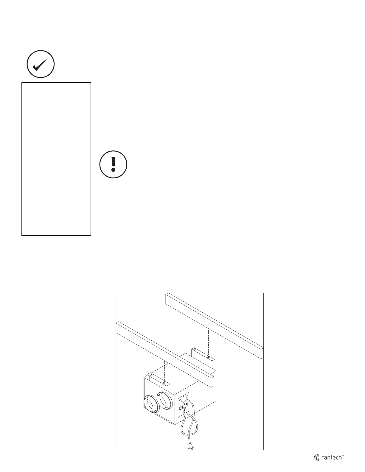
AEV installation
• Install the unit close to the
outside wall on which the
supply and exhaust hoods
will be mounted.
• Have a nearby power
supply 120 Volts, 60 Hz.
• Have the possibility of
mounting the unit to
supporting beams.
• Mount the unit as level as
possible.
• Have a certain amount
of heat around the unit
(attic installation is not
recommended).
• Minimize any noise level
that would be created by
the unit in the living area.
• Have access for future
maintenance.
9
Location
The Air Exchanger must be located where it will be possible to conveniently service the unit. Typically the AEV would
be located in an area close to the outside wall where the weatherhoods will be mounted. If a basement area is not
convenient or does not exist, a utility or laundry room may be used.
Connecting appliances to the AEV is not recommended. These include:
• Clothes dryer
• Range top
• Stovetop fan
• Central vacuum system
These appliances may cause lint, dust or grease to collect in the HRV, damaging the unit.
Connecting any of these types of appliances to the AEV will void your warranty.
Mounting
1. Although we recommend installing the unit as shown, the flexibility offered by our centrifugal external rotor motor allows for the unit to be installed
in any position.
2. Use screws and mounting bracket supplied with the unit.

10
Flow
Airflow balancing
The balancing procedure consists of measuring the exhaust air leaving the system and the supply
air entering the system and ensuring that these two are equal. A deviation of 10% or less is
acceptable. In such cases, it is recommended to have a greater amount of exhaust air than supply
air as so to increase the supply air’s temperature.
• If the unit’s airflows are not properly balanced...
- The unit may not operate at it’s maximum efficiency.
- The unit’s use could cause negative or positive pressure in your home causing
cold air to enter or other combustible equipment to backdraft.
A The duct’s airflow velocity is measured with a magnehelic gauge and a pitot tube. See “Pitot Tube
Balancing Procedure” next page.
Duct
B This airflow measuring station reads the airflow by being connected to the ducting.
Air
Pitot
Tube
Magnehelic
c
eli
gne h
a
M
Gauge
To avoid airflow turbulence and incorrect readings, the airflow velocity should be measured on steel
ducting a minimum of 18” (457 mm) from the unit or elbow and before any transition.
18”
(460 mm)
Measure
here
 Loading...