

Page 1

C
Call 1-800-667-8721 anywhere in the US and Canada - www.kitchensource.com
IMPORTANT - PLEASE READ THIS
AEV Series
Air Exchange Ventilator
MANUAL BEFORE INSTALLING UNIT
CAUTION -
tem will operate if connected to any other piece of mechanical equipement,i.e. a forced air
furnace or air handler,operating at a higher static.After installation, the compatibility of the
two pieces of equipment must be confirmed by measuring the airflow’s of the Air Exchange
Ventilator by using the balancing procedure found in this manual.
It is always important to assess how the operation of any AEV may interact with vented
combustion equipment (i.e. Gas Furnaces,Oil Furnaces,Wood Stoves,etc.).
NEVER - install a ventilator in a situation where its normal operation,lack of operation
or partial failure may result in the backdrafting or improper functioning of vented combustion equipment!!!
Before installation,careful consideration must be given to how this sys-
C
C
R
US
Your ventilation system should be installed in conformance with the appropriate provincial or state requirements or in the absence of such requirements with the current edition of the National Building Code, and /
or ASHRAE’ s “ good Engineering Pratice”.
AEV Models
INSTALLATION, OPERATION AND MAINTENANCE MANUAL
AEV 1000
Fan Tech at
kitchen
U N L I M I T E D
::
accessories
Page 2
Call 1-800-667-8721 anywhere in the US and Canada - www.kitchensource.com
The Best
Limited W arranty
in the Business
• The motors found in all Fantech AEV’s
require no lubrication,and are factory
balanced to prevent vibration and
promote silent operation.
• The limited warranty covers normal use.
It does not apply to any defects,
malfunctions or failures as a result of
improper installation,abuse, mishandling,
misapplication,fortuitous occurrence or
any other circumstances outside
Fantech’s control.
• Inappropriate installation or
maintenance may result in the
cancellation of the warranty.
• Any unauthorized work will result in
the cancellation of the warranty.
• Fantech is not responsible for any
incidental or consequential damages
incurred in the use of the ventilation
system.
• Fantech is not responsible for providing
an authorized service centre near the
purchaser or in the general area.
TABLE OF CONTENTS
TECHNICAL DATA
AEV Series ......................................................................................................................1
OPERATION ................................................................................................................................. 2
Modes Of Operation ................................................................................................................2
Optional Remote Controls..................................................................................................... 3
INSTALLATION............................................................................................................................ 4
Mounting the Unit ................................................................................................................... 4
Location & Ducting................................................................................................................... 5
Examples ..................................................................................................................... 7
Air Flow Balancing ................................................................................................................... 8
MAINTENANCE .....................................................................................................................11
TROUBLESHOOTING.............................................................................................................13
• Fantech reserves the right to supply
refurbished parts as replacements.
• Transportation,removal and installation
fees are the responsibility of the purchaser.
• The purchaser is responsible to adhering
to all codes in effect in his area.
• The warranty is limited to 5 y
parts and 7 years on the motor from the
date of purchase,including par ts replaced
during this time period.If there is no
proof of purchase available, the date
associated with the serial number will be
used for the beginning of the warranty
period.
* This warranty is the exclusive and only
warranty in effect relative to the ventilation
system and all other warranties either
expressed or implied are invalid.Please fill
out the warranty registration and return it
within two weeks of purchase or the
warranty will be voided.
ears on
Sizining (Example) for maximum airflow normally required.
AEV’s are typicaly sized to be able to ventilate the whole house at a maximum of 1/3 of an
air change per hour.To calculate this simply take the square footage of the home (including
basement)
multiply by the height of the ceiling to get cubic volume,and then multiply that by .005.
Example: SQFT of House 1100
Basement 1100
Total SQFT 2200
Height of ceiling x 8
Cubic volume 17600
x .005
Maximum airflow required (CFM) 88
* Always consult your local code for sizing requirements in your area.
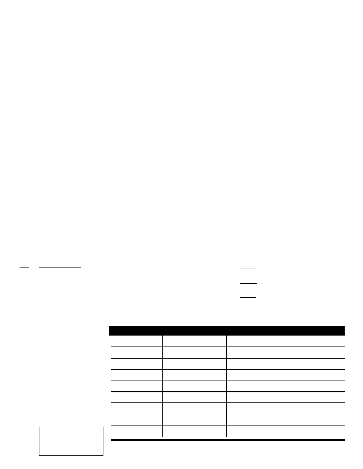
Room classification Number of rooms CFM (L/s) CFM Required
Master bedroom x 20 cfm (10 l/s) =
Basement yes or no =
Bedrooms x 10 cfm (5 l/s) =
Living room x 10 cfm (5 l/s) =
if yes add 20 cfm / 10 l/s
if no = 0
Others x 10 cfm (5 l/s) =
Kitchen x 10 cfm (5 l/s) =
Bathroom x 10 cfm (5 l/s) =
Laundry room x 10 cfm (5 l/s) =
1 cfm = 0.47189 l/s
1 l/s = 3.6 m
3
/hr
Utility room
Fan Tech at
x 10 cfm (5 l/s) =
Total ventilation Requirements
kitchen
U N L I M I T E D
::
accessories
(add last column )
=
Page 3

TECHNICAL DATA
C
Call 1-800-667-8721 anywhere in the US and Canada - www.kitchensource.com
Components
CASE - 22 gauge galvanized steel with powder coat paint, lined with strong top
quality insulation.
FILTER - Synthetic high quality filter for better indoor air quality and clean air .
UNIT CONTROLS - Case mounted rocker switches provide the following functions.
ON/OFF switch is to engage the operations of the ventilation system.
At OFF position,the system can still achieve high speed from the
remote dehumidistat or optional timer switch.LOW/MED switch is to
control the continuous ventilation mode. At LOW speed, the system
will be operating at its lowest ventilation requirement.At MED speed,
the system will operate to meet building codes requirements according
to sizing and design conditions.
REMOTE OVERRIDE -24 volts (low voltage) remote switching circuit for high speed
operation to reduce the humidity level in the dwelling.This is archieved
by a dehumidistat,an optional timer switch or any indoor air quality
(IAQ) remote sensor
BLOWERS - The motors are factory-balanced to prevent vibrations,providing
greater comfort without noise pollution.
-Fans equipped with motors of insulation class “B”
- The motors are completely sealed , keeping out moisture, dust and
lint.
- The motors feature maintance-free bearings and are the most
dependable and efficient on the market.
- Built-in thermocontact prevents overheating
- Increased corrision protection
AEV Series Performance Data
Airflow Cap.L/s (cfm)
Model
AEV 1000 49 (104) 38 (60) 20 (42)
High
Med Low
AEV Series Electrical Data
Model Volts Amp Rating
AEV 1000 115 V 0.6 A
All of the AEV models are 120V unless specified otherwise.
C
C
R
US
Dimensions
Fan Tech at
kitchen
U N L I M I T E D
::
accessories
1
Page 4

Call 1-800-667-8721 anywhere in the US and Canada - www.kitchensource.com
OPERATION
An Air Exchanger Ventilator (AEV) is designed to provide fresh air into a building while exhausting an equal amount of stale air.
During the winter months,the incoming cold fresh air is warmed by mixing it with return air before it is supplied to the home.
During summer months when the indoor space is air conditioned,the AEV will help in cooling the incoming fresh air with the
stale air that is being exhausted.
Fantech AEV’s are designed to run continuous or on intermittent,giving the homeowner complete control over their air quality.
Continuous low speed ventilation is recommended,which will help eliminate carbon dioxide, voc’s and other gases as well as
freshen up the home.Intermittent high speed ventilation can be obtained through a variety of optional remote controls found in
this manual (page 3 ).Below are some examples of seasonal operation of an AEV.
Winter:
Humidity control is very important during the winter months. This is when problems will be most apparent since
condensation on the windows will often occur. The colder the outside temperature,the greater the risk of condensation in the home.The average relative humidity should be maintained between (30-60) to avoid condensation.Low speed continuous ventilation with high speed override is recommended.
Spring:
Temperatures are more moderate and become warmer each day. To keep the humidity and temperature uniform,
set the dehumidistat higher and the switch on the AEV to standby.
Summer:
The air is sometimes hot and humid. To stop the warm humid air from entering,set the dehumidistat at its highest level and the switch on the AEV to standby.
Fall:
Rain and rapid temperature changes make it difficult to control the internal humidity level and may result in condensation on the windows.A remote dehumidistat may help give greater control over the inside environment.
NOTE:Some products may not be exactly as illustrated in the Installation,Operation and Maintenance Manual.
Fantech Inc. reserves the right to modify,at any time and without notice, any or all of its products’ features,designs, components
and specifications,to maintain their technological leadership position.
2
Fan Tech at
kitchen
U N L I M I T E D
::
accessories
Page 5

OPERATION (CON’T)
OPTIONAL REMOTE CONTROLS
Call 1-800-667-8721 anywhere in the US and Canada - www.kitchensource.com
PRACTICAL
TIPS
To avoid window
condensation:
• It is not necessary to change
the humidity control every
day.Monitor the average
weekly temperature or
experiment with various
settings until you find a level
that is comfortable for you.
Adjust the control when
needed.
Dehumidistat I
The wall mount dehumidistat monitors the humidity level in
the area it is installed.When the humidity level rises above the
desired set-point, the AEV will activate to high speed/override
mode. Once the humidity level returns to desired condition,
the unit will return to the normal mode.
2 low voltage wires required for operation.
Air Quality Sensor
The wall mount Air Quality Sensor (AQS) monitors indoor
air quality and activates the override mode when carbon
monoxide,formaldehyde,benzene, volatile organic
compounds and other pollutants are detected. The unit will
then return to normal mode once the air pollutants are
reduced to a pre-determined lower level.
Three low voltage wires are required for operation with
transformer
* This control is not a warning device.
* All controls are low voltage. 18 to 24 gauge wire is recommended.
Fan Tech at
kitchen
U N L I M I T E D
::
accessories
3
Page 6

INSTALLATION
PRACTICAL
TIPS
• Install the unit close to
the outside wall on
which the supply and
exhaust hoods will be
mounted.
• Have a nearby power
supply 120 Volts,60 Hz.
• Have the possibility of
mounting the unit to
supporting beams .
• Mount the unit as
level as possible.
• Have a certain amount
of heat around the unit
(attic installation is not
recommended).
Call 1-800-667-8721 anywhere in the US and Canada - www.kitchensource.com
LOCATION
The Air Exchanger must be located in a heated space where it will be possible to conveniently service the unit.Typically the AEV would be located in the mechanical room or an
area close to the outside wall where the weatherhoods will be mounted.If a basement area
is not convenient or does not exist,a utility or laundr y room may be used.
Attic installations are not normally recommended due to:
- the complexity of work to install
- freezing conditions in the attic
- difficulty of access for service and cleaning
Connecting appliances to the AEV It is not recommended,incuding:
- clothes dryer
- range top
- stovetop fan
- central vacuum system
These appliance may cause lint,dust or grease to collect in the AEV ,damaging the unit.
NOTE: Connecting any of these type of appliances to the AEV will invalidate your warranty
MOUNTING
• Although we recommend installing the unit as shown,the flexibility offered by our centrifugal
external rotor motor allows for the unit to be installed in any position.
• Use #10 wood screws plus vibration insulator grommets supplied with the unit.
• Minimize any noise
level that would be
created by the unit in
the living area.
• Have access for future
maintenance.
4
Fan Tech at
kitchen
U N L I M I T E D
::
accessories
Page 7

Call 1-800-667-8721 anywhere in the US and Canada - www.kitchensource.com
INSTALLING DUCTS GOING TO / FROM OUTSIDE
A well designed and installed ducting system will allow the AEV to operate at its maximum efficiency.
Always try to keep duct runs as short and straight as possible.
See Installation Diagrams for installation examples.
PRACTICAL
TIPS
• Decide where your intake and
exhaust hoods will be located.
Locating the Intake
Weatherhood
• Should be located upstream
(if there are prevailing winds)
from the exhaust outlet
• At least 6’(2m) from the
exhaust weatherhood
• At least 6’(2m) away from
dryer vents and furnace
exhaust ( medium or high
efficiency furnaces)
• A minimum of at least 6’
(2m) from driveways,oil fill
pipers, gas meters, or
garbage containers
• At least 18”(457mm) above
the ground,or above the
depth of expected snow
accumulation
• At least 3’(1m) from the
corner of the building
• Do not locate in a garage,
attic or crawl space
INST ALLING THE DUCTING
TO THE WEA THERHOODS
The inner liner of the flexible insulated duct
must be clamped to the sleeve of the
weatherhoods (as close to the outside as
possible) and to the appropriate port on the
AEV. The insulation should remain full and
not be squished. The outer liner,which acts
as a vapor barrier must be completly sealed
to outer wall and the AEV using tape and or
caulking. A good bead of high quality
caulking (preferably acoustical sealant) will
seal the inner flexible duct to both the AEV
port and the weatherhood prior to
clamping.
To minimize air flow restriction, the flexible
insulated duct that connects the two
outside weatherhoods to the AEV should be
stretched tightly and be as short as possible.
Twisting of folding the duct will severely
restrict air flow.
Locating the Exhaust
Weatherhood
• At least 6’(2m) from the
ventilation air intake
• At least 18”(457mm) above
ground or above the depth of
expected snow accumulation
• At least 3’(1m) away from
the corner of the building
• Not near a gas meter, electric
meter or a walkway where
fog or ice could create a
hazard
• Not into a garage, workshop
or other unheated space
When installing the
weatherhood,it’s outside
perimeter must be sealed with
exterior caulking.
1 Using the collar of
the outside hood,
outline the intake &
exhaust holes to be
cut. The holes should
be slightly larger
than the collar to
allow for the
thickness of the
insulated flexible
duct.Cut a hole
fo r both th e intake
and exhaust hoods.
2 Pull the insulated
Fan Tech at
flexible duct through
the opening until it is
well extended and
straight.Slide the
duct’s inner vinyl
sleeve over the hood
collar and secure,
pull the insulation
over the duct and
then the vapour
barrier over the
sleeve and secure
with duct tape.
kitchen
U N L I M I T E D
::
accessories
3 Push the hood into
the opening.Attach
the hood to the
outside wall with
mounting screws.
Repeat the
installation procedure
for both the Supply
and Exhaust hood.
4 Using a caulking
gun,seal around
both hoods to prevent any leaks.
5
Page 8

Call 1-800-667-8721 anywhere in the US and Canada - www.kitchensource.com
INSTALLING DUCTS TO / FROM INSIDE (CON’T)
Exhaust Air ducting
The stale air exhaust system is used to draw air from the points in the house where the worst air quality problems occur. It is
recommended that return air ducts be installed in the bathroom,kitchen, and laundr y room. Additional return air ducts from
strategic locations (i.e. greenhouse, atrium,swimming pool, sauna, etc .) may be installed. The furnace return duct may be also
used to exhaust from. In this method,the exhaust air is not ducted back from bathrooms,kitchens, etc to the AEV with “dedicated lines”.
This method has become popular and provides good ventilation when installed in accordance with the instructions. The furnace
blower must be running when the AEV is operating for this method to be effective.
PRACTICAL
TIPS
• For new construction,
the rigid ducts are run
in the walls.
• Choose the loction your
Supply and Exhaust
Fantech grille {MGE
(metal) or PGE
(plastic)}s. The Supply
grilles should be located
in every habitable room
and the Exhaust Grilles
should be located in the
wet rooms.
• A piece of flexible
ducting should be placed
between the Suppy Air In
and Out collar of the AEV
and the rigid ducting to
absorb any noise or
vibrations.
Dedicated installation for existing home - non force air
heating / cooling system.
1 Begin with the duct collar marked “Exhaust Air In”. Slide a short piece
(12”) of flexible duct over the duct collar.Using duct tape, tape the
flexible duct to the collar.Run the flexible ducting to the main rigid
duct trunk line, which connects to the remainder of the ducts going to
and from rooms in the house..Repeat the steps for the “Supply Air
Out” on the side of the AEV.
2 Working from a closet,attic or inside your joist wall, run the length of
ducting required for the proper grille location and cut a hole in the
gyprock.Fasten the mounting collar (optional) to the ducting and
fasten the collar to the wall or ceiling with screws.
3 The Fantech grille {MGE (metal) or PGE (plastic)} airflow can be
adjusted by rotating the inside unit.It is recommended that the grilles
be completely opened at first and then adjusted later as needed.
• For proper network
of ducting,see TYPES
OF INSTALLATIONS.
• The grilles are to be
installed on the ceiling or
on the wall 6”(152 mm)
to 12”(305 mm) from
the ceiling.
4 Push the Fantech grille {MGE (metal) or PGE (plastic)} into the optional mounting collar or
directly into installed elbow.
6
Fan Tech at
kitchen
U N L I M I T E D
::
accessories
Page 9

Call 1-800-667-8721 anywhere in the US and Canada - www.kitchensource.com
INSTALLATION (CON’T)
Radiant, Hydronic and Electric Baseboard Heating
• This diagram shows the installation of your unit with radiant hydronic or baseboard heating.
As shown,the stale air is extracted from the rooms with high humidity levels,and the fresh air is delivered in the living areas.In
this case,a complete ducting system for ventilation must be installed.
PRACTICAL
TIPS
*Follow local building codes*
Fan Tech at
kitchen
U N L I M I T E D
::
accessories
7
Page 10

AIR FLOW BALANCING
PRACTICAL
TIPS
• If the unit’s airflows are not
properly balanced...
- The unit may not operate at
it’s maximum efficiency.
- The unit’s use could cause
negative or positive pressure
in your home causing cold air
to enter or other combustible
equipment to backdraft.
• The balancing procedure consists of measuring the exhaust air leaving the system and the
supply air entering the system and ensuring that these two are equal.A deviation of 10% or
less is acceptable. In such cases, it is recommended to have a greater amount of exhaust air
than supply air as so to increase the supply air’s temperature.
Call 1-800-667-8721 anywhere in the US and Canada - www.kitchensource.com
A*
Pitot tube and gauge
Duct
Flow
Air
e
gn
Ma
Pitot
Tube
Magnehelic
c
i
l
e
h
Gauge
AThe duct’s airflow velocity
is measured with a
magnehelic gauge and a
pitot tube. See “Pitot Tube
Balancing Procedure” next
page.
B*
B This airflow measuring
station reads the
airflow by being
connected to the
ducting.
18”
(460 mm)
Measure
here
• To avoid airflow
turbulence and
incorrect readings,the
airflow velocity should
be measured on steel
ducting a minimum of
18” (457 mm) from the
unit or elbow and
before any transition.
8
Fan Tech at
kitchen
U N L I M I T E D
::
accessories
Page 11

Call 1-800-667-8721 anywhere in the US and Canada - www.kitchensource.com
AIR FLOW BALANCING (CONT’)
B
1 For this flow measuring station,cut
the duct and place the flow
measuring station between each
station.Make sure that the flow
measuring station’s air direction
arrow points in the direction of the
airflow.Secure the flow measuring
station with duct tape.
PITOT TUBE BALANCING PROCEDURE
PITO T TUBE
BALANCING PROCEDURE
The following is a method of field balancing an AEV using a Pitot
tube, advantageous in situations when flow stations are not
installed in the ductwork. Procedure should be performed with
the AEV on high speed.
The first step is to operate all mechanical systems on high
speed,which have an influence on the ventilation system,i.e.the
AEV itself and the forced air furnace or air handler if applicable.
This will provide the maximum pressure that the AEV will need
to overcome,and allow for a more accurate balance of the unit.
Drill a small hole in the duct (about 3/16), three feet downstream of any elbows or bends, and one foot upstream of any
elbows or bends.
These are recommended distances but the actual installation
may limit the amount of straight duct.
The Pitot tube should be connected to a magnehelic gauge or
other manometer capable of reading from 0 to 0.25 in (0-62 Pa)
of water, preferably to 3 digits of resolution. The tube coming
out of the top of the pitot is connected to the high pressure side
of the gauge. The tube coming out of the side of the pitot is
connected to the low pressure or reference side of the gauge.
Insert the Pitot tube into the duct; pointing the tip into the airflow.For general balancing it is suffivient to move the pitot tube
around in the duct and take an a v erage or typical reading.Repeat
this procedure in the other (supply or return) duct. Determine
Fan Tech at
kitchen
U N L I M I T E D
2 Before taking the reading,make sure
that the magnehelic gauge is level
and at 0.Refer to the flow
measuring station’s chart to
determine your unit’s airflow
velocity.
which duct has the highest airflow (highest reading on the
gauge). Then damper that airflow back to match the lower reading from the other duct. The flows should now be balanced.
Actual airflow can be determined from the gauge reading. The
value read on the gauge is called the velocity pressur e. The Pitot
tube comes with a chart that will give the air flow velocity based
on the velocity pressure indicated b y the gauge. This velocity will
be in either feet per minute or metres per second. To determine
the actual airflow,the velocity is multiplied by the cross sectional areas of the duct being measured.
This is an example for determining the airflow in a 6” duct.
The Pitot tube reading was 0.025 inches of water.
From the chart,this is 640 feet per minute.
The 6” duct has cross sectional area of
The airflow is then:
640 ft./min.x0.2 square feet-128cfm
For your conv enience,the cross sectional area of some common
round duct is listed below:
DUCT DIAM.(inches) CROSS SECTION AREA (sq ft.)
5 0.14
6 0.20
7 0.27
The accuracy of the air flow reading will be affected by how
close to any elbows or bends the readings are taken. Accuracy
can be increased by taking an av erage of multiple r eadings as out-
::
accessories
lined in the literature supplied with the Pitot tube.
3 The airflow is regulated by a
balancing damper located inside the
collar of the AEV.Adjust the “Supply
Air Out” damper until you reach
the desired velocity.Follow the
previous
steps to adjust the “Exhaust Air
Out” damper.
= [3014x(6” 12)2 4
=0.2 squeare feet
9
Page 12

Call 1-800-667-8721 anywhere in the US and Canada - www.kitchensource.com
PITOT TUBE BALANCING PROCEDURE (CONT’)
M
a
g
neh
e
l
ic
c
i
l
e
h
e
n
g
a
M
* Pitot tube should be kept at least 12” away from fans elbows and dampers to ensure acurate reading.
10
Fan Tech at
kitchen
::
accessories
U N L I M I T E D
Page 13

Call 1-800-667-8721 anywhere in the US and Canada - www.kitchensource.com
MAINTENANCE
CAUTION MAKE SURE UNIT IS UNPLUGGED BEFORE ATTEMPTING ANY MAINTENANCE WORK
The following components should also be inspected regularly and well maintained.
PRACTICAL
TIPS
• To prevent electrical shock,
check that the unit is
unplugged before doing any
repairs or maintenance.
• A yearly inspection is
recommended to ensure the
efficiency and trouble-free
use of your system. Run
through the system
and verify the different
operating modes.
The motor - The motor
are factory balanced and
lubricated for life. They
require no maintenance.
The unit - The inside of
the unit should be vacuumed yearly. Be careful not
to damage any of the
mechanical components
and electrical connections.
Outside hoods - The outside hoods need to be
checked every season to
make sure there are no
leaves or insects blocking
the airflow. Check regularly that there are no pollutants near the intake hood.
Make sure they are clear of
any snow accumulation
during the winter months.
FILTER
The filter needs to be checked
and cleaned every three months
or when it appears dirty. To
clean, remove the filter and vacuum. If the filter still appears
dirty, it can be washed in warm
sudsy water (mild detergent).
Replace the filter if it becomes
too soft after washing. The filter
should be replaced yearly or
when it can no longer be
cleaned properly. You may have
to change the synthetic filter
after washing a few times.
OUTSIDE HOODS
The outside hoods need to be
checked every season to make
sure there are no leaves or
insects blocking the airflow.
Check regularly that there are
no pollutants near the intake
hood. Make sure they are clear
of any snow accumulation
during the winter months.
NOTE:Some products may not be exactly as illustrated in Installation,Operation and Maintenance manual.
Fan Tech at
kitchen
U N L I M I T E D
::
accessories
11
Page 14

SERVICING
Call 1-800-667-8721 anywhere in the US and Canada - www.kitchensource.com
PARTS LIST
Description Part #
1 Motorized Impeller 500000
2 Filter 017068
3 Override Relay Board 410150
4 Capacitor 410428
5 Auto-Transformer 410350
6 Control Panel 200422
7 5” Collar 530172
8 Filter Door 200426
9 Access Panel 203939
12
Fan Tech at
kitchen
U N L I M I T E D
::
accessories
Page 15

TROUBLESHOOTING
Call 1-800-667-8721 anywhere in the US and Canada - www.kitchensource.com
Problem
Air is too dry
Air is too humid
Persistent condensation
on window
Poor Air Flows
Dehumidistat control is set too low
AEV out of balance
Dehumidistat control is set too high
Sudden change in temperature
Storing too much wood for heating
Dryer vent exhaust is inside home
Poor air circulating near windows
AEV out of balance
Basement door is closed
Improper adjustment of dehumidistat
control
AEV out of balance
-1/4” (6mm) mesh on the outsid hoods
is plugged
-filter plugged
-house grilles closed or blocked
-dampers are close if installed
-poor power supply at site
-ductwork is restricting AEV
-improper speed control setting
-AEV airflow improperly balance
SolutionsCauses
Increase the desired level of humidity. Change ventilation mode from
continuous mode to standby.
Balance AEV
Reduce the desired level of humidity.Combine this step with use of
continuous exchange mode.
Wait until outside temperature stabilizes (winter).Heating will also
improve situation.
Store a majority of your wood outside.Even dried, a cord of wood
contains more than 20 gallons of water.
Arrange outside vent for dryer.
Open curtains or blinds. Bay or bow windows may require mechanical
method.
Balance AEV
Open the door or install a grill on the door.
Reduce the desired level of humidity.Combine this with the use of
continuous exchange mode.
Balance AEV
-clean exterior hoods or vents
-remove and clean filter
-check and open grilles
-have electrician check supply voltage at house
-check duct installation
-increase the speed of the AEV.
-have contractor balance AEV
Supply air feels cold
-poor location of supply grilles,the airflow may irritate the occupant
-outdoor temperature extremely cold
AEV and / or Ducts
Frosting up
Condensation or Ice
Build Up in Insulated
Duct to the Outside
-AEV air flows are improperly balanced
-malfunction of the AEV system
-incomplete vapour barrier around
insulated duct
-a hole or tear in outer duct covering
Fan Tech at
-locate the grilles high on the walls or under the baseboards,install
ceiling mounted diffuser or grilles so as not to directly spill the supply
air on the occupant (eg.Over a sofa)
-turn down the AEV supply speed. A small duct heater (1kw) could
be used to temper the supply air
-placement of furniture or closed doors is restricting the movement
of air in the home
-if supply air is ducted into furnace return,the furnace fan may need
to run continuously to distribute ventilation air comfortably
-Note:minimal frost build-up is expected
-have HVAC contractor balance the AEV
-Duct heaters
-tape and seal all joints
-tape any holes or tears made in the outer duct covering
-ensure that the vapour barrier is completely sealed.
kitchen
U N L I M I T E D
::
accessories
13
 Loading...