

Page 1

OPERATING MANUAL
Manual version 0111
FAGOR NC-200 PB
NC FOR
PRESS BRAKES
Page 2

Operating Manual NC-200 PB
INDEX
Diagram of a typical press BRAKE..................................................................... 0
Introduction....................................................................................................... 1
Description of the various machine models .......................................................... 1
1. Unit description.................................................................................... 2
1.1 Front panel............................................................................................. 2
2. Coordinate display. Auxiliary modes ................................................... 4
2.1 Display modes........................................................................................ 5
2.2 Selection of tools and types of material to bend ....................................... 6
2.3 Type of material ...................................................................................... 7
2.3.1 Generate the whole elasticity factor table for a new unknown material........ 9
2.3.2 Generate the elasticity factor of a single angle by testing
the bending depth .................................................................................. 10
2.3.3 Generate the elasticity factor by trial and error and correct the angle ......... 12
2.3.4 Saving and recalling the material-type tables through
the serial line RS-232 ............................................................................. 13
2.3.5 Restoring initial tables ............................................................................ 14
3 Operating modes................................................................................ 14
3.1 Manual /set mode .................................................................................. 14
3.1.1 Manual movement from the NC keyboard ............................................... 15
3.1.2 Movement with the foot switches. "C" model ......................................... 15
3.1.3 Manual movement to a particular "X" position, "Y" depth or "a" angle.... 16
3.1.4 Manual movement by external means ...................................................... 16
3.2 Machine reference (home) search ........................................................... 17
3.2.1 Sequence for axes with mandatory home search on power-up ................. 17
3.2.2 Sequence for axes without mandatory home search................................. 18
3.2.3 Sequence for the Y axis. Model B .......................................................... 18
3.3 Tool table loading .................................................................................. 19
3.3.1 Recall initial tool values .......................................................................... 19
Page 3

NC-200 PB Operating Manual
4 Programming ..................................................................................... 20
4.1 Program editing ..................................................................................... 20
4.1.1 Editing / Deleting an existing program ..................................................... 20
4.1.2 Editing a new program ........................................................................... 22
4.2 Inserting / deleting blocks in a previously edited program ........................ 27
4.3 Deleting all the programs ........................................................................ 27
5 Execution Modes with control from the foot switches and
manual station. Models A1, B, C....................................................... 28
5.1 Program execution................................................................................. 30
5.2 Execution in semiautomatic mode........................................................... 32
6 Operation with the RS-232-C serial line ........................................... 32
6.1 Saving and restoring data ....................................................................... 32
6.2 Parameter transmitting format ................................................................. 33
6.3 Program transmitting format ................................................................... 33
6.4 Transmission of material-type tables ....................................................... 33
Appendix ........................................................................................................ 34
Error codes ...................................................................................................... 34
Maintenance...................................................................................................... 35
Page 4
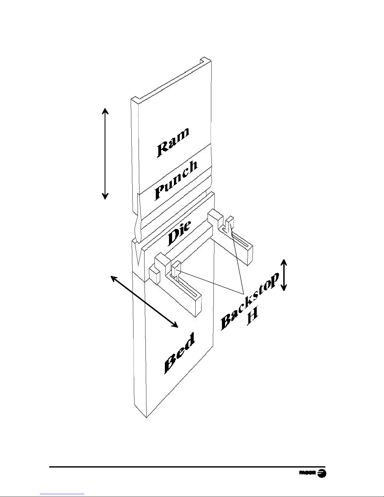
Operating Manual NVP-200 PB - page 0 -
Y
X
+
-
-
+
DIAGRAM OF A TYPICAL PRESS BRAKE
Page 5

NC-200 PB - Operating Manual - Page: 1
INTRODUCTION
Throughout this manual, certain installation parameters are referred to which
affect the description of certain NC functions.
These parameters have been set by the installer and may be modified by the
operator.
These parameters are described in the installation manual supplied with this unit.
DESCRIPTION OF THE VARIOUS MACHINE MODELS
This manual mentions different machine models (A, A1, B, C) that are built quite
differently; but they don't differ as much when using the resources of this
numerical control whether they are up-stroke or down-stroke models.
A. Controlling only the final position of the bend for simple machines that do not
require distinguishing 4 execution modes.
The foot switches, the execution modes and the hydraulic circuit are not handled
by this unit.
The intermediate positions of the ram cannot be preset.
They are detected with electrical micro-switches.
A1. Same as model A with foot switch control and outputs to control the hydraulic
valves handling the 4 EXECUTION modes.
Especially indicated for conventional down-stroke machines.
B. Same as model A1 with a linear feedback or digital potentiometer to read the
actual position of the ram or the table. This allows detecting the intermediate
positions that may be selected at the NC:
- Top dead point. FAST/SLOW change position.
- FAST/SLOW change position.
- Sheet metal holding position. End of the bend.
Very useful for up-stroke models.
C. Control of the actual movement of the ram / table / apron and presetting of
intermediate positions.
Page 6
Page: 2 - Operating Manual - NC-200 PB
1. UNIT DESCRIPTION
This NC is especially designed to be used on press brakes. It allows displaying
the position of the vertical and horizontal axes as well as executing partprograms and also moving the axes manually from this NC's keyboard or by
external means.
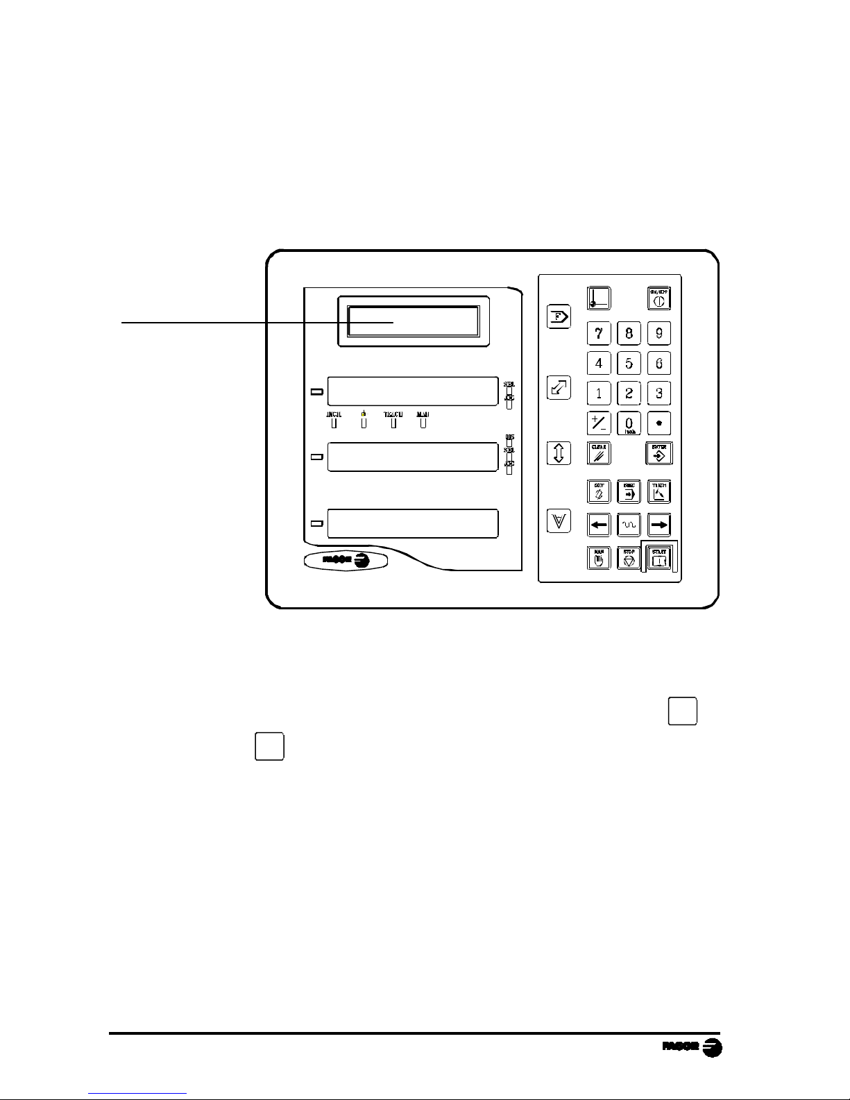
1.1 FRONT PANEL
Message display
The message display offers assistance to facilitate the operating modes of
this NC.
When using an LCD screen,
its contrast may be adjusted by pressing 3 to
decrease it or
9
to increase it.
Page 7
NC-200 PB - Operating Manual - Page: 3
Each axis display has eight 14.1 mm high LEDs and another one for the minus
sign (-).
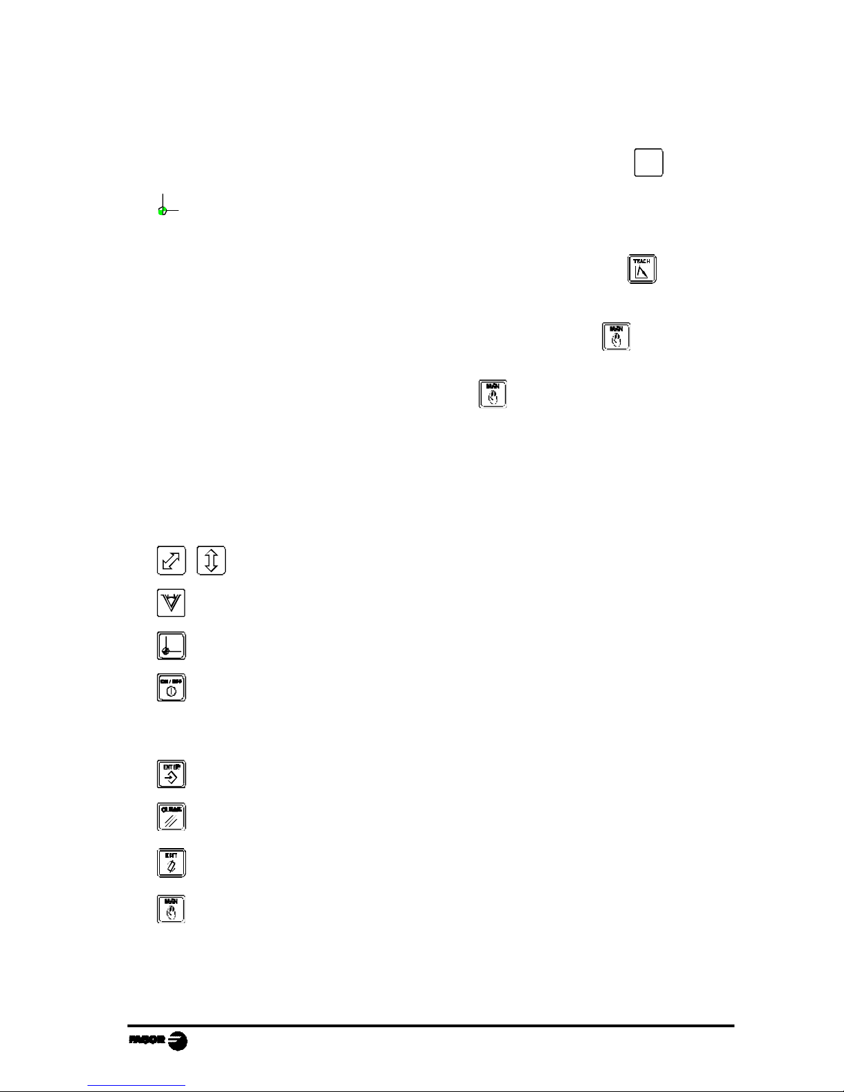
INCH- Inch mode selection. To access it or quit it, press
0
inch
Machine reference search mode which is accessed by selecting
the SET mode.
TEACH - TEACH-In mode which is accessed by pressing
when the
editing mode is selected (on the screen for coordinate selection).
MAN - Manual mode which is accessed by pressing
There are two ways to access it:
Models A and B . Using the
keyy
Model C - By selecting the SET mode.
SEL - Axis selected.
JOG - Axis moving.
DIS - Y axis disabled (selector switch in position 5).
Select the X and Y axis respectively.
Program the bending angle or the width of the die's "V".
Machine reference zero (home) search.
Turn the display off while keeping track of the axes position at all times.
This key must be pressed before turning the unit's power off by the main
switch on the back of the unit.
Validate an operation.
Cancel or abort an operation already initiated.
Access the program or tool editing mode.
Access the manual mode.
Page 8
Page: 4 - Operating Manual - NC-200 PB
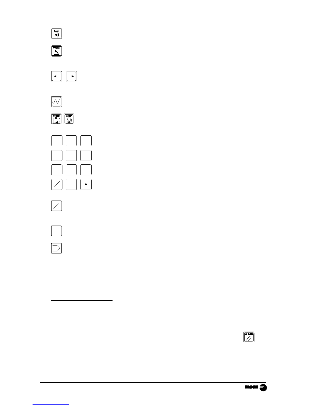
Access the program execution mode.
Program blocks after moving the axes to the desired position while in
editing mode (Teach-in mode).
Move the axes in MANUAL mode in both directions and to move
back and forth from one menu option to another.
Move the axes manually at fast feedrate.
Execute and interrupt, respectively, the execution of a program.
987
4 5 6
321
-
+
0
inch
Enter data.
-
+
Change the sign of the value being entered and to eliminate the last digit
of the X and Y axes.
0
inch
Toggle between metric and inch display.
F Access the special operation modes, parameter setting, communications
via RS-232-C, etc.
2. COORDINA TE DISPLAY. AUXILIARY MODES
Turning the unit ON
The unit is turned on by actuating on the power switch of the rear panel
This NC runs a self-test and its LCD screen shows the text:
Fagor NC-200 PB, the 1st and 2nd displays show "Fagor NC". Press and
if there is an error, the displays will show the error number if otherwise. See the
appendix at the end of this manual.
Page 9
NC-200 PB - Operating Manual - Page: 5
Turning the unit OFF
If you press key the NC turns off the displays while maintaining the power
supply to the feedback systems and goes on reading the position of the axes at
all times. This is not the case when the equipment is turned off by means of the
switch on the rear panel of the same.
To reset the displays, just press this key again as long as that the NC is getting
voltage (plugged in and with the switch on the rear panel on).
Notes:
- Before powering the NC down with the switch on the rear panel or disconnecting
it from mains, it is a good idea to press the key in order to store the current
position of the axes permanently.
- If the unit is powered down with its rear panel switch or there is a power outage
without previously having pressed , the NC will keep the last position of
the axes for at least 30 minutes.
- The unit will display ERROR 2 when powered back up if the position reading
was lost when turned off while the axes were moving or after the accidental
backup period has expired without having saved the current position by
previously pressing
.
2.1 DISPLAY MODES
Language selection
On this NC, it is possible to select the language used for displaying the help on
the LCD screen. To do this:
- Access parameter PAR50 (language) directly by pressing
5
0
inch
- Press
-
+
repeatedly until the desired language appears (English, Spanish,
French, German, Italian, Portuguese, custom*) and press .
Press to quit the language selection mode.
"Custom" may be any user defined language. (See section 3.4 PAR52 of the
installation manual).
Page 10
Page: 6 - Operating Manual - NC-200 PB
Conversion mm into inches
This NC can displayed the position of the axes in millimeters or inches by
pressing
0
inch
key depending on whether the INCH led is off or on respectively..
Turning off the last digit of the X and Y displays
This NC allows a decimal digit to be switched off (coarse resolution) when the
resolution is excessive, simply by pressing
-
+
. For example 0.01 instead of
0.012.
2.2 SELECTION OF TOOLS AND TYPES OF MATERIAL TO BEND
In the initial mode, it is possible to set a particular punch-die set and also the
bending pressure as well as the characteristics of a particular material.
This data will only be assumed when machining in MANUAL mode. Section 3.1.
·Press F
· Use to select <Tool> and press to access to the selection page:
[punch number] [·] [die number] and press
Maximum pressure when using a pressure gage (transducer),
[Sheet thickness]
[Number of associated table (0 to 19)]
Press to exit.
This unit assumes the offsets indicated in the tool table. See section 3.3.
· The screen shows the number of the selected tooling.
Punch, die 1.1
· The position shown on the Y axis display corresponds to the relative distance
between the edge of the punch and the top side of the die.
The final bend position is always negative.
Page 11

NC-200 PB - Operating Manual - Page: 7
2.3 TYPE OF MA TERIAL
The type of material depends on a number of factors that make it impossible to
foresee its behavior in order to calculate the depth "Y" of the punch according
to the programmed angle αα.
This problem is solved using the TEACH-IN editing mode that forces the
operator to make several bends by trial and error until obtaining an acceptable
result and memorize the "Y" depth associated with the requested angle αα.
This is a very time-consuming task because it has to be repeated for all the
programmed angles. A program stored in memory must be executed with the
same tools used in the TEACH-IN process. The width of the die forces its
geometry.
Using the elasticity factor associated with each material exceeds the capabilities
of a conventional TEACH-IN editor that only requests the depth of the bend:
· It is a programmable parameter that is assumed together with the thickness of
the sheet metal in the N0 block of each program.
· It associates certain constants, in a table format, for 8 fixed values multiple of
10 between 50º and 120º.
· It calculates (prorates) the factor corresponding to intermediate angles.
· It is also possible to store in the table 5 special values associated non-multiple
of 10 or out of the 50º-to-120º range, if they will be repetitive in future bends
with the same material.
· The TEACH-IN editor (section 4.1.2) offers the option to load a new factor for
special angles or modify the value stored in the table that matches a typical angle
to be corrected.
· This unit has resources to generate the tables for unknown material types and
to set corrections based on the original ones to adapt them to materials
supposedly very similar to the standard ones offered here and described in later
chapters.
· For white sweet sheet metal F114 (resistance < 50 Kg), the factor is barely
affected by the width of the die. The same program may be executed with
different tools with results very similar results as for the mentioned materials and
similar punch radii. It will only require a slight correction.
If the A aperture of the die is larger than the one used in the tries, the resulting
angle will be slightly greater.
Page 12
Page: 8 - Operating Manual - NC-200 PB
By default, this unit has some initial tables stored in nonvolatile memory and
cannot be modified. This table may be used as a sample for typical materials and
there is a modifiable copy of this table under factor numbers M0 to M19.
Either the non-modifiable factors M21 through M41 or the modifiable ones M0
through M20 when programming the header page N0.
There is a specific way, section 2.3.3, to recover the initial tables that serve as
a reference and correspond with the following materials and tools where:
Punch radius of 1 mm:
A = Die width
r = Die edge radius
e = Material thickness
Ri = Inside bending radius.
In order to obtain the same results with the suggested tables, we
recommend to use dies with an edge radius r = A/10 and an aperture
A = 8 x e. On sweet steel, Ri = A/6
Material A r e
M0 Reserved for inflexible materials
M1 Aluminum 12 1 1
M2 Aluminum 16 1.5 1.5
M3 Aluminum 20 2 2
M4 Aluminum 24 2.5 3
M5 Reserved
M6 White sheet < 48 Kg mm2 12 1 1
M7 White sheet < 48 Kg mm2 16 1.5 1.5
M8 White sheet < 48 Kg mm2 16 1.5 2
M9 White sheet < 48 Kg mm2 20 2 2.5
M10 White sheet < 48 Kg mm2 24 2.5 3
M11 Reserved
M12 Reserved
M13 Reserved
M14 Reserved
M15 Stainless steel 12 1 0.5
M16 Stainless steel 12 1 0.75
M17 Stainless steel 12 1 1
M18 Stainless steel 16 1.5 1.5
M19 Stainless steel 16 1.5 2
Page 13

NC-200 PB - Operating Manual - Page: 9
2.3.1 GENERA TE THE WHOLE ELASTICITY FACTOR TABLE FOR
A NEW UNKNOWN MA TERIAL
Tables 0 through 19 are open to the machine operator. They may be changed
with the NC's own resources or uploaded from a PC. They represent each
operator's experience.
M0 should be reserved for inflexible materials that do not require bending radius
compensation. See example in Section 2.3.2
In initial mode, press F
On the "Materials" menu, select <New> and press
The EXECUTION mode is accessed in the same way adding a canned cycle that
offers a sequence to check the elastic behavior of the new material.
The first page defines the tools:
[Punch number] [·] [Die number]
[Sheet thickness]
[number of the associated table (1 to 19)
Knowing the tool dimensions and the sheetmetal thickness, this NC has the
necessary geometrical data to suggest consecutive trial bends for 8 angles
between α = 130º and the minimum α supported by the die selected for the trial.
Press to test the 1st angle of 130º:
The axis displays the sequential trial number, from 1 to 8.
The axis displays the approximate bending depth to know the trial stage.
· Press , the Y axis positions at the theoretical depth corresponding to 130º
to execute the first bend.
Once executed and when the ram or the base reaches the withdrawal position,
go to the new page that requests an angle. Enter the real angle obtained and
press .
The reading and entering of data may be automatic when using the FAGOR
electronic angle measuring device connected directly to this NC.
· Repeat this sequence until completing the whole table.
Page 14

Page: 10 - Operating Manual - NC-200 PB
After accepting the last angle, it calculates the whole table of elasticity factors
associated with the angles multiple of 10, thus concluding the trial.
These factor are stored in the selected table.
This trial may be aborted by pressing after completing a bend, but the factors
of the angles already tested will not be stored.
Take certain precautions and maintain a criterium that helps classifying the
materials according to their elasticity, hardness or traction resistance factors:
Type Characteristics of the material
1,2,3,4 Aluminum of different thickness and very hard sheet metal (70 HRB)
that breaks when bent.
5-14 White sweet sheet metal (F114) of different thickness and hardness.
15-20 Very flexible sheet metal: stainless steel, steel 134, etc.
Once their bending limit has been exceeded, the characteristics of the material
change. The limit angle depends on the thickness, type of material and punch
radius on inflexible materials.
The material type number must be indicated for the 8 suggested angles with sheet
metal that should not have been previously bent at greater angles.
This NC does not offer resources to display the data saved in the tables. It is
recommended to write down the values of the "αα" angle and "Y" depth related
to each type of material and the die number used in the trials.
2.3.2 GENERA TE THE ELASTICITY F ACTOR OF A SINGLE ANGLE
BY TESTING THE BENDING DEPTH
This method is recommended to determine very accurately a single bending
angle by testing an unknown material or an angle way out of the 50º-120º range
even if it belongs to a table already tested.
In initial mode, press F
Use to select <mat> (materials) and press
On the "Materials" menu, select <1> and press
Page 15

NC-200 PB - Operating Manual - Page: 11
The TEACH-IN EDITING mode is accessed in the same way.
The first page defines the tools and type of material.
[punch number] [·] [die number]
[sheetmetal thickness]
[number of associated table (0 to 19)]
Once all four data have been entered, the NC may access the TEACH-IN mode.
Press (at the "C" model, select "SET" first).
·Press and key in the αα value to be tested and press to make the trial
bend. An approximative result will be obtained.
·Using the resources of the continuous or incremental MANUAL mode, fine
tune the Y coordinate and repeat the trial.
·Select position 5 of the MANUAL selector switch to disable the Y axis and the
"DIS" led will turn on.
Some manufacturers offer resources to move the axis with means external to the
NC (typical method on up-stroke machines with a handwheel for manually
correcting the leadscrew position.
Once the right angle has been achieved, usually by trial and error, press
Select <Yes> and press
Measure and indicate the obtained angle.
and press
The relevant elasticity factor is stored. This procedure may be repeated for
several angles until its full capacity is filled: 8 multiples of 10 (from 50º to º120º)
+ 5 intermediate. When exceeded, it displays the message: "Memory full".
Save correction?
Yes<No>
Save correction?
Angle
Page 16

Page: 12 - Operating Manual - NC-200 PB
Practical examples:
With a factor of M0, the material is supposed
to be inflexible without inside bending radius.
a) - With M0, r = 0, e = 0, α = 90,
A = 24
Bending depth Y = -12
b) - With M0, r = 0, e = 3, α = 90,
A = 24
Bending depth Y = -7.726
2.3.3 GENERATE THE ELASTICITY FACTOR BY TRIAL AND ERROR
AND CORRECT THE ANGLE
Method recommended when trying to correct the elasticity factor of some
material that has been already tested and shows some dispersions.
In initial mode, press F
Use to select <Mat> and press
On the "Materials" menu, select <2> and press
The first page defines the type of material.
[punch number] [·] [die number]
[sheetmetal thickness]
[Number of associated table (0 to 19)]
Once all the data has been entered, this NC is ready to access the correction
mode.
Press . The display blinks "000".
Set the bending angle and press
The "Y" axis reaches the position corresponding to the selected angle and
makes the trial bend.
The characteristics of the material must be close to the selected elasticity
factor.
The result is an angle close to the suggested one. It must only differ in ±5º
for the correction to be accurate.
Page 17

NC-200 PB - Operating Manual - Page: 13
· Press
The screen shows the option:
Select "Yes" and press . The blinks "000".
· Indicate the actual resulting angle with a maximum resolution of 0.1º and
press
2.3.4 SAVING AND RECALLING THE MATERIAL-TYPE TABLES
THROUGH THE SERIAL LINE RS-232
The material type number is an empirical value (obtained through a custom
algorithm) that cannot be interpreted.
It is recommended to save the initial tables offered by this NC and use them as
references for certain very specific materials.
Each press brake operator may create his/her own tables and save them using
a PC with a communications software like HYPERTERMINAL (available in
Windows version) or "Procom" in MS-DOS version.
This method is only recommended when wanting to have the tables of more than
20 materials.
The procedure and format are described in chapter 5.
Save correction?
Yes<No>
Page 18

Page: 14 - Operating Manual - NC-200 PB
2.3.5 RESTORING INITIAL T ABLES
In initial mode, press F
Select <Mat> (Materials) with and press
Select <Delete> and press
· To restore the material type (elasticity factor) for a single material:
Indicate the table number, 1 to 19, displayed on the 3rd display and press
· To recover all the initial tables:
Indicate Nr. 99 and press
A dot comes on at the 1st and 2nd display.
Press again. Two dots are lit.
Press F . 2 dots are lit and it offers two choices (are you sure?).
Use to select <Yes> and press
While the tables are being loaded, the message screen shows the message:
"Deleting materials...". M0 to M19 restore the initial values of the table.
3 OPERATING MODES
3.1 MANUAL /SET MODE
There are two ways to access: Models A & B: With
Model C: Selecting the "SET" mode.
The MAN led turns on.
This mode also sets the slow Y axis speed below the speed change position
(PAR33).
If any of the axes reaches the software limits set by PAR12 and PAR13 or the
travel limit switches are activated, this unit issues an error message; but it allows
moving the axes in the opposite direction to return to the work area.
Page 19

NC-200 PB - Operating Manual - Page: 15
If PAR16 has been set with leadscrew backlash value, position reading will be
ignored when reversing the turning direction. Once the backlash has been made
up for, this unit resumes position reading. This is particularly noticeable when
using continuous jogging or the Y axis has been enabled and it is moved by
external means.
If PAR17 has been set to "1" or "2", when moving the axes in continuous or
incremental jog mode, in back and forth movements, this unit assumes the
unidirectional approach.
To quit the MANUAL mode, press or change the switch to a position other
than SET.
3.1.1 MANUAL MOVEMENT FROM THE NC KEYBOARD
- Select the axis to be moved with its relevant key or .
- Press
or and the axis will start moving in either direction at slow
feedrate. To move it fast, press
at the same time and keep it pressed..
- To stop the movement,
1st release the key and 2nd release SLOW..
Otherwise, it keeps moving at the feedrate set by PAR26.
Depending on the position of the
MANUAL switch, the movement will be
continuous or incremental . Positions 1
through 4 (clockwise) in the drawing
below.
3.1.2 MOVEMENT WITH THE FOOT SWITCHES. "C" MODEL
In SET mode, actuating upon any foot switch forces the (Y) axis preset.
In MANUAL mode, using the up and down foot switches is the same as using
the keys that only affect the Y axis.
The foot switches are also operative in INCREMENTAL JOG mode.
Cont.
jog
Incr.1
Incr.2
Incr.3
Disable Y
Semiauto
1
2
3
4
5
Page 20

Page: 16 - Operating Manual - NC-200 PB
3.1.3 MANUAL MOVEMENT TO A PARTICULAR "X" POSITION,
"Y" DEPTH OR "αα" ANGLE
- Select the MANUAL mode with or with "SET" at the "C" model.
- Select the axis:
or to define the position.
For negative values, press
-
+
after the coordinate.
To define the bending angle compensating the active tools and
type of material.
The selected display keeps blinking.
- Request a value and press . The axis will move until it reaches the indicated
position.
To interrupt this movement before reaching its target, press
To resume the movement, repeat this process selecting the a new position value.
In MANUAL mode, it always assumes the "SET" type work mode. Two foot
switches control the up and down movement of the ram in sensitive mode while they
are pressed (A1, B and C models).
The associated elasticity table cannot be modified.
Press to exit.
3.1.4 MANUAL MOVEMENT BY EXTERNAL MEANS
- When disabling the "Y" axis by setting the jog switch in the corresponding
position (position 5 in the drawing below), the "DIS" led will turn on and the "Y"
axis will be free to be moved by external means. The NC will display the axis
position and will watch for its travel limits.
Cont.
jog
Incr.1
Incr.2
Incr.3
Disable Y
Semiauto
1
2
3
4
5
Page 21

NC-200 PB - Operating Manual - Page: 17
3.2 MACHINE REFERENCE (HOME) SEARCH
If machine parameter PAR14.4 = 1, the home search is mandatory on one or
both axes on power-up. Whenever any axis has been moved while the NC was
turned off, the axis that has been moved must be homed.
Parameter PAR14.1 distinguishes the sequence depending on whether home
switches or used or not.
3.2.1 SEQUENCE FOR AXES WITH MANDA TORY HOME SEARCH
ON POWER-UP
On power-up, pressing activates the mode. Select or .
a. If the axis has a home switch, this unit displays the word: "START".
If it is the Y axis, make sure that the ram is at the top position touching
the home switch.
Press to force the automatic search.
b. If the axis does not use home switches, usually on Y, it will indicate a value that
corresponds with the value of PAR10.
Actuate on the "BEND" foot switch until the ram reaches its final position.
Measure the distance between the support sides of the punch and die and preset
that value (Yref).
A wrong value too different from the real one may cause uncontrolled
movements of the axis.
Press . It displays the Y coordinate (Y = Yref - Hpunch - Hdie) compensating
the height of the active tools.
Exit pressing . The led turns off.
If on power-up, you wish to quit the home search mode without actually homing,
press and key in the access (or quit) code: 719200.
Page 22

Page: 18 - Operating Manual - NC-200 PB
3.2.2 SEQUENCE FOR AXES WITHOUT MANDATORY HOME
SEARCH
In initial mode, press . Depending on the characteristics of the machine,
there are two choices:
a. If both axes have home switches, the turns on. This unit displays the word
"START" when accessing freely or accessing only when the ram is at
the top position.
Press .
b. If any axis does not have a home switch, usually the Y, this unit requests the
password 719200 to access the mode and assumes that the values set by the
OEM are to be modified. This is only recommended in case of a breakdown
or when updating this unit's software version.
For the affected axis, proceed as described in section 3.2.1b
3.2.3 SEQUENCE FOR THE Y AXIS. MODEL B
Proceed as indicated in 3.2.1a. and add the synchronization sequence:
a.- with a linear encoder.
At the reference position, bend to the bottom until the ram is stopped and
press to balance the reading of the axes Y-Y'.
b.-With a linear potentiometer.
1- Press and it displays the potentiometer value in volts in
MANUAL mode.
2- Press
3- Move the "Y" axis with to the far end position, towards Y-.
Activate the BEND foot switch again up to the final position.
Press again.
Press to exit.
Page 23

NC-200 PB - Operating Manual - Page: 19
Edit
Prg Punch Die
3.3 TOOL T ABLE LOADING
With this NC, it is possible to load the data of up to 10 sets of punches and dies.
This data refers to the height of the punch (from 0.000 mm and 9999.999 mm),
to the height of the die, width of the die, "V" (from 0.000 mm to
9999.999 mm), die angle that limits the bending depth and its edge radius (from
0 to 99.9).
To do this:
- Access the editing mode by pressing
The screen shows three options:
Select "Punch" and press
- Choose the tool number using or keying the number..
- Indicate the punch height: [value]
- Press to exit.
Select "Die" and press
- Choose the tool number.
- Indicate the die aperture with: [value]
- Indicate the die height with: [value]
- Indicate the die angle with: [value]
- Indicate the die edge radius with: [value]
- Press to exit
· Before quitting this mode, it is recommended to check that none of the 9 table
positions contains data exceeding the range with a code EEEEEEEE.
By default, the whole table contains some initial values:
Hpunch = 0, Hdie = 0, A = 16, r = 1.6 that may be recalled.
3.3.1 RECALL INITIAL TOOL VALUES
While in punch or die editing mode, press the sequence:
F F
The unit will request confirmation of this command. Select <Yes> and
press to restore the initial values.
Page 24

Page: 20 - Operating Manual - NC-200 PB
4 PROGRAMMING
This NC can store up to 200 program blocks.
The program memory may be locked setting installation parameter PAR51(1)=1
This way, the program blocks cannot be edited or deleted.
In the initial teach-in stage, it is recommended to work with the simple resources
only as a positioning dro without attributes and with a material factor M0 which
only compensate for the rounding radius Rex = sheet metal thickness.
Once familiarized with them, it is possible to expand the resources of the materialtype tables, program ANGLES with the same capabilities as specific CNC's for
press brakes. To access this simple mode (without attributes):
(The assumes the default values of D and T set by PAR29 and PAR30).
·Press
5 1
·Press
8
to activate the bit and confirm with
· Exit by pressing
Programs edited in conversational mode keep the attributes even when not
displayed in EDITOR mode if PAR51.8 has been activated
4.1 PROGRAM EDITING
In a program, it is possible to "Edit" new blocks, "Modify" the data already
programmed in the blocks or "Delete" all their contents leaving them free (empty).
4.1.1 EDITING / DELETING AN EXISTING PROGRAM
- Press to access the block editing
mode.
- Select "Prg" using the keys and
press
- Use the keys to select the desired
program to be modified (they are not
stored sequentially).
- Press
Edit
Prg Punch Die
Program Editing
Program ....: 0000
Program Editing
Program ....: 0007
Page 25

NC-200 PB - Operating Manual - Page: 21
- Use the keys to select the option
(Edit or Delete).
- Select "Delete" to delete a program from memory..
- Select "Edit" to modify..
It access the program block N0.
Only some values of the parameters affecting the geometry of the bend
may be modified:
· Die number (with different width).
· Elasticity factor (type of material).
· Sheet metal thickness.
When pressing , if the corrector has been stored, it recalculates all the
following blocks that have been programmed by indicating the ANGLE
in order to adapt them the new parameters of the N0 block and it will
confirm that each one of them with two beeps.
- Use the keys to move to the
previous and next blocks respectively.
Edit the data of the block using the
procedures of the Editing mode described
in section 4.1.2 and press .
When modifying on the "Select axis" or "Attributes" screen, it may require
pressing two or three times to accept the new value and assume it. The
sequence ends with a blinking of the "#" symbol at the upper right hand of the
screen and it is confirmed with two beeps.
- To learn how to insert a new block, see section 4.2
- To quit the Editing mode, press .
Editing P0007 N00
Select Tool
Program Nr. Block Nr.
Program Editing
Edit Delete
Page 26

Page: 22 - Operating Manual - NC-200 PB
4.1.2 EDITING A NEW PROGRAM
To edit a new program, pressing gives access to editing the header of the
program (Block N00). The specific data for each bend take two screens pages.
Use the key to go from one page or one block to the next while validating the
data just entered.
Use the keys to select the page to be displayed; but only on the block
being edited (it is not possible to go back to the previous block).
After validating a block, it is not possible to go back to it in order to change a value
in it. To do this, finish editing the whole program and then proceed as described
in section 4.1.1.
Before accepting a data on the "Y" axis, in all the editing modes, it analyzes the
requested bending depth and it cannot be written if they exceed the width of the
die.
The "angle" indicated when loading the tool data serves as a reference to force the
safety limit Yminimum.
Editing with the key indicating the angle as described in this chapter marks
the relevant block to recalculate the bending depth "Y" when modifying any data
of the header block N0: active die, elasticity factor or sheetmetal thickness.
If programmed with the , depth only, it is not recalculated when changing the
data of block N0.
It must be machined with the same die that was chosen in editor mode.
Page 27

NC-200 PB - Operating Manual - Page: 23
The program editing procedure is as follows:
1st page. Header / Tool selection page
Select the "punch Nr./die Nr." set to
be used.
Select the maximum pressure in tons.
(Only on machines with electronic pressure
reading).
Sheet metal thickness, press
Material type, between 1 and 19, press
The last two data define the characteristics of the sheet metal and are displayed
together on the 3rd display.
Once accepted, press to go on to...
2nd page. Select X, Y values of 1st block, N1
It offers 3 modes:
a. Conventional editing: Presetting numeric values.
- Press and key in the X position of the bend.
- There are two ways to set the depth of the bend:
1-Pressing and keying in the final Y position of the bend or---
2-Pressing and keying in the angle a directly..
When pressing , this unit analyzes the material type table and
calculates the bending depth based on the thickness of the sheet metal
and the opening and radius of the die and it stores this value on the Y
axis (always negative).
The data for bending depth and angle are displayed at the same time.
Editing P0007 N00
Select Tool
Program Nr. Block Nr.
Page 28

Page: 24 - Operating Manual - NC-200 PB
b. Teach-in editing. Storing only the bending depth
With this method, it is also possible to execute parts by making single bends
without leaving the editing mode and it is ideal for individual bending operations
with unknown materials.
The X value is set in the conventional way, by setting a value.
- On a "C" model. Select the SET position.
- Press . The TEACH and MAN leds turn on. By default, the is selected.
( may be forced only to modify the X axis position).
This unit then offers all the resources of the MANUAL mode for positioning the
axes with the following options:
1- Key in the position and press
The selected axis will move to this position.
2- Continuous or incremental manual movement using the keys or the
foot switches on the "C" model.
3- When selecting position 5 of the MANUAL selector switch, the Y axis is
disabled and the "DIS" led turns on. Some manufacturers offer the possibility
to move the "Y" axis by external means (not using this NC). This is very
common on "A" type up-stroke presses having handwheels.
Once the correct angle has been achieved through trial and error if the material is
unknown, press . It suggests the position reached as the coordinate to be
edited; but it may be corrected.
Press to go on to the attributes page.
To exit the Teach-in mode, press or
Page 29

NC-200 PB - Operating Manual - Page: 25
c. Teach-in editing storing the angle with resources to correct the active
elasticity table.
Ideal method for materials with known elastic behavior identifiable with a
table already tested.
The X value is defined using the conventional method.
At the "C" model, select the "SET" position.
· Press . The TEACH and MAN leds turn on.
It selects the axis .
· Press , indicate the bending angle and press
The "Y" axis reaches the position corresponding to the angle selected for
the trial bend.
The characteristics of the material must be close to the selected elasticity
factor.
The resulting angle will be close to the suggested one. It must only differ
in ±5º for the correction to be accurate.
· Press
The screen shows the option:
Select "Yes" and press . The display blinks "000".
· Indicate the resulting actual angle with a maximum resolution of 0.1º and
press to go on to the attributes page.
Going back with it is possible to confirm the correction of the "Y" depth
corresponding to the suggested angle which will be indicated on the
display with the proper elasticity factor.
The same result is assured in the following blocks having the same angle
and edited the conventional way [angle]
If at the end of the trial, there are data changed out of the range for the "Y"
depth value , the selected table should be erased to restore the initial values.
See section 2.3.5.
Save correction?
Yes<No>
Page 30

Page: 26 - Operating Manual - NC-200 PB
3rd page. Attributes
Key in the number of times that block
is to be executed.
If n = 0, the block is ignored.
Auxiliary data.
Each function is represented by its
abbreviation on the display. Each attribute
is activated or canceled by pressing its
associated key, 1, 2, 3 or 4.
"t" (timing) . Apply a delay at the beginning of the block before moving the
X axis. By default, it shows the time period set by PAR30.
To set another value, press again, key in a value between 0 and
9.9 seconds (shown on the 1st display) and validate it with .
"h" (height). Activate the "H" output.
"b" (back). Retract the X axis when the punch presses on the sheet metal
according to the conditions set by parameters PAR36, PAR37.
4
"d" (delay). Hold the punch back at the end position once the bend has been
completed. By default, it shows the value set by PAR29.
To set another value, press
4
again, key in a value between 0 and
9.9 seconds (shown on the 1st display) and validate it with .
Top dead point. By default, it offers the value of PAR28; but any other value
may be preset (only on machines with ram / table position decoder).
To store the data, press . It is confirmed with two beeps and it access the page
for selecting the X and Y values, of the next bend, press .
The values set for the "t" and "d" attributes accessed with the
1
and
4
keys
exclude each other. It is assigned to the last attribute from the one it was requested
(and shown on the 1st display "t=2" or "d=4"). If one of the two attributes is active,
but it is not shown on the 1st display, it assumes the value set by the relevant
parameter PAR30 or PAR29.
Editing P0000-N01
Attributes
Editing P0000 N01
1T 2H 3B 4D
Page 31

NC-200 PB - Operating Manual - Page: 27
The attributes are assumed at the beginning of each block before executing the
movements of the axes.
The "t" attribute is only active if it corresponds with an approach movement of the
X axis.
In EXECUTION mode, they appear on the screen with the letters: T, H, B, D
blinking if they are affecting the bending operation.
The end of the program does not require any special instruction. To quit the editing
mode, press . The last block opened when recognizing the block edited last
is not stored.
To modify a value, go back to , select the program, move to the desired block
using the key, replace the value and validate it by pressing
(see section 4.1.1).
4.2 INSERTING / DELETING BLOCKS IN A PREVIOUSL Y EDITED
PROGRAM
Select the previous block as described in section 4.1.1
- Press F .
The LCD screen will shows the options to "Insert" and "Delete ".
- With the "Insert" option, an empty block is created and inserted after
the selected block and the numbers of the next blocks are increased by
one.
Note : No block may be inserted after the header block N00.
- The "delete" option eliminates the selected block. The following numbers
decrease by 1.
- Block N0 cannot be deleted.
- To delete a whole program, see section 4.1.1.
4.3 DELETING ALL THE PROGRAMS
To delete all the programs, once in "program edit" mode, press the
sequence: F F
It requests confirmation Yes/No with
Page 32

Page: 28 - Operating Manual - NC-200 PB
5 EXECUTION MODES WITH CONTROL FROM THE FOOT
SWITCHES AND MANUAL STATION. MODELS A1, B, C
5 stages may be distinguished when executing a block:
1. Previously positioning of the X and Y axes.
Some machines have a specific button that the operator must press to force the
X axis approach.
To start the bending sequence, both axes must reach the programmed position.
A buzzer may be installed to indicate the order to the operator.
2. RAPID approach.
It is only possible if activated from the manual station.
When reaching the speed change point, it changes to SLOW.
3. Bending from the foot switch station depending on the selected mode. RUN1
and RUN2 are the most common ones.
Conditioned by the "B" attribute, the X axis may be forced to return when
holding the sheet metal.
4. Delay at the final position at maximum pressure conditioned by the
programmable "D" attribute.
5. Return to the top dead point.
In the RUN 1 and RUN 2 modes, the return is automatic once the delay time
has elapsed.
At the "C" model with safety pressure gage the bending process is aborted when
exceeding the limit value and it returns to the top dead point thus preventing tool
damage.
Up to 4 modes may be selected with an external switch. These modes distinguish
the way the "BEND" or "RETURN" foot switches respond. The rapid approach
controlled from the manual station is not described here.
If the pressure gage has a manometer key, in RUN1 and RUN2 modes, the return
of the ram may be timed ("D" attribute) if PAR51.7=1 is activated (recommended
only for small parts that are easy to handle).
RUN 1
SET
JOG
RUN 2
1
2
3
4
Page 33

NC-200 PB - Operating Manual - Page: 29
RUN 1 - CONTINUOUS, STOP WHEN RELEASING THE FOOT SWITCH
a. Hold the "BEND" foot switch down so the axis starts moving SLOWLY.
b. Releasing the foot switch interrupts the movement.
Pressing the "RETURN" foot switch, it returns to the top dead point.
c. Once the position and the bending pressure have been reached, the foot
switch may be released. The return is not affected by the status of the foot
switch. It is automatic when the bending time has elapsed.
d. To go on to the next block, release the pedal if it was kept pressed until the
top dead point is reached.
RUN 2 - SIMPLE, RETURN TO THE TOP DEAD POINT WHEN
RELEASING THE FOOT SWITCH
a. Hold the "BEND" foot switch down so the axis starts moving SLOWLY.
b. When releasing the foot switch, it returns to the top dead point.
c. Once the position and the bending pressure have been reached, the foot
switch may be released. The return is not affected by the status of the foot
switch. It is automatic when the bending time has elapsed.
d. To go on to the next block, release the foot switch if it was kept pressed until
the top dead point is reached.
SET - IT FORCES THE MANUAL MODE IN THE "C" MODEL
BEND ALL DAY DOWN AND RETURN WITH TWO FOOT
SWITCHES
It is also assumed in Manual mode, home search and TEACH-IN.
a. Hold the "BEND" foot switch down so the axis starts moving SLOWLY.
b. Releasing the foot switch interrupts the movement.
Pressing the "RETURN" foot switch forces the return movement in
sensitive mode while it is being pressed.
c. While the "BEND" foot switch is kept pressed, the cycle is interrupted when
both the final position and pressure have been reached.
The return is not automatic.
d. To return to the top dead point, press the "RETURN" foot switch.
The preset bending delay "D" is ignored.
Page 34

Page: 30 - Operating Manual - NC-200 PB
JOG - APPROACH AND RETURN CONTROLLED BY A SINGLE FOOT
SWITCH
a. Holding the "BEND" foot switch pressed, it starts moving SLOWLY.
b. Releasing it interrupts the movement.
Keeping the "RETURN" foot switch pressed forces the return movement in
the sensitive mode.
c. Once the final position has been reached, keep the "BEND" foot switch
pressed to complete the bend and start the return movement.
Releasing the foot switch interrupts the sequence even in the final return
movement to the top dead point.
d. To go on to the next block, release the foot switch after the top dead point
is reached.
5.1 PROGRAM EXECUTION
To execute a program:
- Access the "Execution" mode by
pressing .
- Select the desired program by keying
its number and pressing or using
the keys.
The message screen shows the status of the
program:
Program Number: P100
Tools assumed: P1 M1
Block Nr. and Nr. of repetition: N01.02
Active attributes: T H B D
When requesting a new program at the display, the word "START" appears
to indicate that the key must be pressed to begin the first bend:
Execution
Program : 0000
Page 35

NC-200 PB - Operating Manual - Page: 31
1.- . Position the axes and approach the ram using the manual station.
Feed the sheet metal.
2.- Press the "BEND" foot switch for bending according to the selected
EXECUTION mode and the active attributes.
3.- Once the bend is completed, the ram returns to the top dead point.
The sequence for the second bend begins automatically.
The axes position at the coordinate set in the 2nd block repeating the successive
bends until the 1st part is completed.
At the end of the last bend, the axes position at the coordinate set in the 1st block
without having to press . It is possible to feed the sheet metal and go on to the
2nd part.
To quit the EXECUTION mode, press twice.
The block may be interrupted at any stage of the bending operation by pressing
and it may be resumed by pressing
In EXECUTION mode, The and axis displays show the actual (real) X
Y position.
El 3rd display offers additional information in real time once the punch touches
the sheet.
· On the "B" and "C" models, it shows the value of the effective angle on the
bending stage.
· On the "A" model, for machines equipped with a pressure gage, it shows the
programmed angle and the real effective pressure on the bending stage when
touching the sheet metal.
Page 36

Page: 32 - Operating Manual - NC-200 PB
5.2 EXECUTION IN SEMIAUTOMATIC MODE
Having the MANUAL selector in position "5" (semiautomatic), this unit does not
execute the next block automatically. The same bend may be repeated over and
over again until the selector switch is turned to a position other than "5".
If while in this execution mode, the key is pressed, the NC will go on to
execute the next block. By pressing the several times, it is possible to select
the desired block to be executed in semiautomatic mode or ignore the ones not to
be executed.
6 OPERATION WITH THE RS-232-C SERIAL LINE
6.1 SAVING AND RESTORING DATA
With this NC, it is possible to save data into a PC or peripheral device and later
restore it by using the RS-232-C serial communications line.
This data is sent out in the following format:
Baudrate as set by PAR90, 8 data bits, 1 stop bit and no parity.
To access this mode:
- Press
F
- Select the "Comm" option (communications) of the LCD display by means
of the and press .
- Select: < Send> and press to send the data out to a PC or peripheral device
or select <Receive > and press to receive data from a PC or peripheral
device.
- Select the type of data to transmit Parameters, Program, and Materials by
means of the keys and press .
Cont.
jog
Incr.1
Incr.2
Incr.3
Disable Y
Semiauto
1
2
3
4
5
Page 37

NC-200 PB - Operating Manual - Page: 33
6.2 PARAMETER TRANSMITTING FORMAT
The format of the transmitted parameters are:
For value parameters: P00 123.123
For binary parameters: P00 10101010
For option parameters: P00 0
For axis parameters: P?? X 123.123 Y 123.123
The number of decimals depends on the selected resolution.
6.3 PROGRAM TRANSMITTING FORMAT
The format is: P000 P0.M0 G0.000 P999.9 X Y R T H B D U
Where: P0000 Program number.
P0 - M0 Punch number . Die number
G0.000 Sheet metal thickness
P999.9 Pressure (LF)
X Y Bend position
R Block execution number
T Delay between blocks (timing).
H Auxiliary output H (high)
B X axis retract
D Punch delay at the end of the bend (Delay)
U Top dead point (up)
6.4 TRANSMISSION OF MATERIAL-TYPE TABLES
In <Send> mode, this NC can send the full table stored in it out to a PC.
In <Receive > mode, this NC can receive one or several materials M00 through
M19 from a PC.
Page 38

Page: 34 - Operating Manual - NC-200 PB
APPENDIX
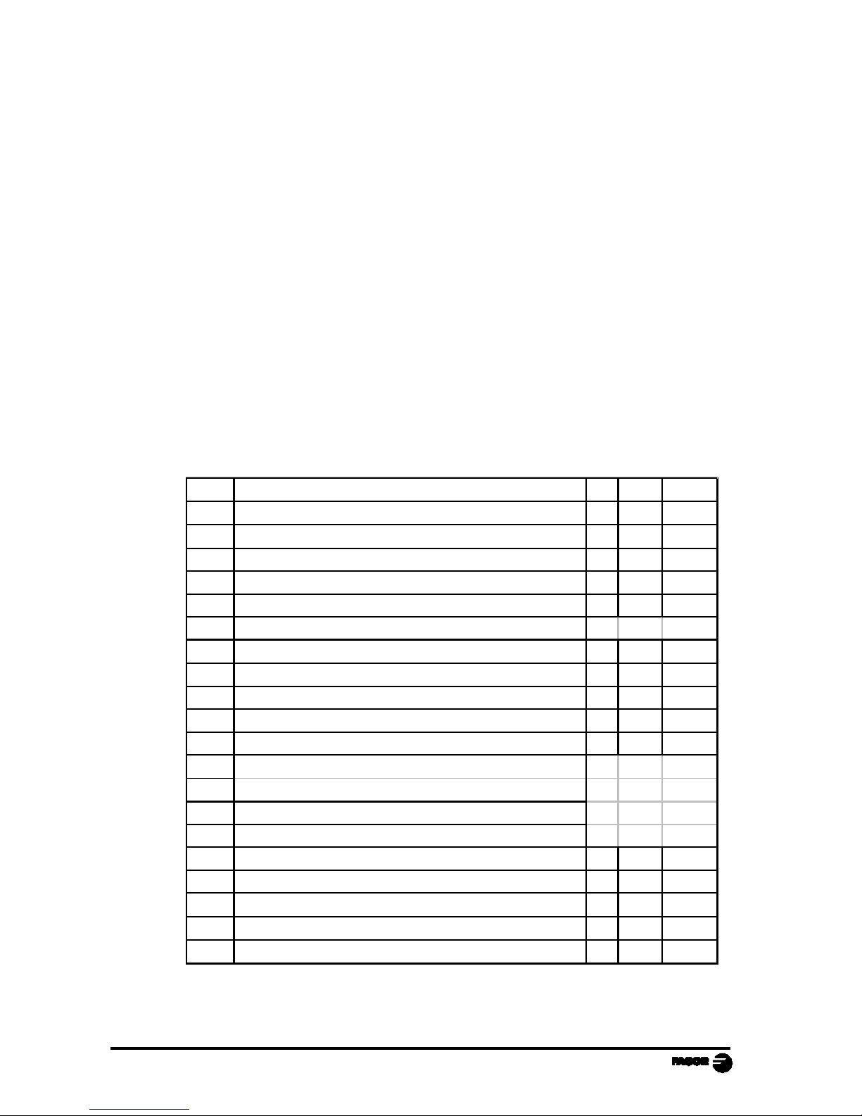
ERROR CODES
Message Description
FAGOR dro
Power outage or turned off by main switch after saving the data.
Error 02
Power outage or turned off by main switch without having saved
the data.
The unit has been turned off without previously pushing the
[ON/OFF] key. It will only lose the position count (will be reset to
zero) and the status of the operating modes (inch, abs, etc.).
Error 04
Wrong parameter values
Error 05 Wrong internal configuration
Error 06
Errors in data backup memory (Service Dept.)
Error 07
Emergency input active. Press [C] or cancel emergency signal.
Error 08 Wrong software memory or the software has been changed
Error 09
Errors in work memory (Service Dept.)
Error 12
Error while searching a coded marker pulse (Io)
Error 20 Travel limit switch pressed on that axis.
Error 31
Internal malfunction (Service Dept.)
Error 32
Internal malfunction (Service Dept.)
Error 90 Internal malfunction (Service Dept.)
Error 99
Internal malfunction (Service Dept.)
. . . . . . . . .
Feedback alarm fromthe feedback device (scale, encoder, etc) or
weak signal.
l.4.3.6.5.7.2.5
Feedback speed too high.
EEEEEEEE
Maximum position reading or speed exceeded when searching
Home
Page 39

NC-200 PB - Operating Manual - Page: 35
If any message other than the first two from the table were to come up, the equipment
should be switched off and on again until one of the first two are seen.
After pressing to access the counting mode, check the parameters.
If any of the errors shown as (Service Department) are often repeated, ask Fagor
Automation’s Customer Services Department about this.
The feedback alarm error will appear if the bit of the corresponding alarm activating
parameter for the axis has been set to "1" PAR08(1) = 1.
In either case, to clear the display, press .
If the axis value is flashing, this means that one of the travel limits established by
machine parameter has been exceeded. This error will be displayed if the alarm
activation parameter for the axis PAR08(2) = 1. All outputs are deactivated
If the NC does not come on or goes out while running, check that the voltage and
ground outlets are as they should be. If an axis does not count, disconnect the
feedback connectors one by one. If the NC comes on, it indicates a fault in the
feedback device. If the fault persists get in touch with Fagor Automation’s Customer
Services Department about it.
MAINTENANCE
Cleaning:
An accumulation of dirt in the equipment can act as a screen preventing proper
dissipation of the heat generated by the internal electronic circuits with the consequent
danger of overheating and NC fault.
Accumulated dirt can also, in some cases, provide a conductive path for electricity which
could give rise to faults in the internal circuits of the equipment, especially in high
humidity conditions.
To clean the equipment nonabrasive dish-washing detergents are recommended (in
liquid, never powder form) or 75% isotropic alcohol with a clean cloth. DO NOT USE
aggressive solvents, (benzol, acetones, etc.) which could damage the materials the
equipment is made with.
Do not use high pressure compressed air to clean the item as this could give rise to an
accumulation of charges which in turn lead to electrostatic discharges.
The plastics used in the front panel of the NC stand up to:
1. Grease and mineral oils.
2. Alkalis and bleaches.
3. Dissolved Detergents.
4. Alcohol
Avoid the effect of solvents such as Chlorohydrocarbons, Benzol, Esters and Ethers
because these could damage the plastics with which the front of the equipment is made.
Preventive Inspection
If the NC does not come on press the rear switch for starting, make sure it is properly
 Loading...