

Page 1

INSTALLATION MANUAL
FAGOR NC-200 PB
NC FOR
PRESS BRAKES
Manual version: 0111
Page 2

Page: 2 - Installation Manual - NC-200 PB
INDEX
Declaration of conformity................................................................................... 4
Safety conditions ............................................................................................... 5
Warranty terms................................................................................................... 7
Material returning terms ...................................................................................... 8
Description of the different models (they may be selected with PAR64) ................ 9
Diagram of a typical press brake ....................................................................... 10
1. Unit description .............................................................................. 11
1.1 Front panel (See operation manual) ..................................................... 11
1.2 Rear panel ......................................................................................... 11
1.3 General technical characteristics......................................................... 12
2. Connections and characteristics ....................................................13
2.1 connection of the feedback systems................................................... 13
2.2 Input/Output characteristics (X2) ....................................................... 14
2.3 Input/output Connection (X2). ........................................................... 15
2.3.1 Input description. .............................................................................. 15
2.3.2 Output description ............................................................................ 17
2.3.3 Input/output connection .................................................................... 18
2.3.3.1 Input/output connection. Model A ..................................................... 18
2.3.3.2 Input/output connection. Model A1 ................................................... 19
2.3.3.3 Input/output connection. Model B ..................................................... 20
2.3.3.4 Input/Output connection. Model C .................................................... 21
2.3.4 Block change synchronism. Models A, A1......................................... 22
2.3.5 Block change synchronism. Model B................................................. 24
2.4 Machine reference (home) search....................................................... 26
2.4.1 X axis home search........................................................................... 26
2.4.2 Y axis reference (home) search. Models A and A1 ............................. 27
2.4.3 Y axis home search. Model "B" ......................................................... 28
2.4.4 Y axis home search. Model "C"......................................................... 29
2.4.5 Precautions when home searching...................................................... 30
2.5 RS-232-C connection (connector X7)............................................... 31
2.6 Power and machine connection .......................................................... 32
2.7 Turning the unit on and off ................................................................ 32
3. Installation Parameters ..................................................................33
3.1 Parameter setting............................................................................... 34
Page 3
NC-200 PB - Installation Manual - Page: 3
Warning:
Before starting up the DRO, carefully read the instructions of
Chapter 2 in the Installation Manual.
The DRO must not be powered-on until verifying that the
machine complies with the "89/392/CEE" Directive.
4. Operation with the RS-232-C serial line ....................................... 49
4.1. Saving and restoring data ................................................................... 49
4.2 Parameter transmitting format ............................................................. 49
5 SETUP............................................................................................ 50
5.1 Test mode ......................................................................................... 50
5.1.1 Direct access to the parameters .......................................................... 53
5.2 Axis setting........................................................................................ 54
5.2.1 Open loop without analog voltage output. P46(3)=0, P46(5)=0 ............ 54
5.2.2 Open loop with analog voltage output. PAR46(3)=1, PAR46(5)=0 ....... 55
5.2.3 Closed loop. PAR 46(3)=1, PAR46(5)=1............................................ 55
Appendix ........................................................................................................ 57
Error codes ...................................................................................................... 57
Maintenance...................................................................................................... 58
Page 4

Page: 4 - Installation Manual - NC-200 PB
DECLARA TION OF CONFORMITY
Manufacturer: Fagor Automation, S. Coop.
Barrio de San Andrés s/n, C.P. 20500, Mondragón -Guipúzcoa
(ESPAÑA)
We hereby declare, under our responsibility that the product:
NC Fagor NC-200 PB
meets the following directives:
SAFETY:
EN 60204-1 Machine safety. Electrical equipment of the machines.
ELECTROMAGNETIC COMPATIBILITY:
EN 50081-2Emission
EN 55011 Radiated. Class A, Group 1.
EN 55011 Conducted. Class A, Group 1.
EN 50082-2 Immunity
EN 61000-4-2 Electrostatic Discharges.
EN 61000-4-4 Bursts and fast transients.
EN 61000-4-5 Power surges
EN 61000-4-11 Voltage fluctuations and Outages.
ENV 50140 Radiofrequency Radiated Electromagnetic Fields.
ENV 50141 Conducted disturbance induced by radio frequency
fields.
As instructed by the European Community Directives on Low Voltage:
73/23/EEC, on Machine Safety 89/392/EEC and 89/336/EEC on Electromagnetic Compatibility.
In Mondragón, on April 1st, 2001
Page 5
NC-200 PB - Installation Manual - Page: 5
SAFETY CONDITIONS
Read the following safety measures in order to prevent damage to personnel,
to this product and to those products connected to it.
Fagor Automation shall not be held responsible for any physical or material
damage derived from the violation of these basic safety regulations.
Do not open this unit
Only personnel authorized by Fagor Automation may open this
unit.
Do not handle the connectors with the unit connected to AC
power.
Before handling the connectors (mains, feedback, etc.) make sure
that the unit is not connected to AC power.
Use proper Mains AC power cables
To avoid risks, use only the Mains AC cables recommended for this unit.
Avoid electrical overloads
In order to avoid electrical discharges and fire hazards, do not apply electrical
voltage outside the range indicated in chapter 2 of this manual
Ground connection
In order to avoid electrical discharges, connect the ground terminals of all the
modules to the main ground terminal. Before connecting the inputs and outputs
of this unit, make sure that all the grounding connections are properly made.
Before powering the unit up, make sure that it is connected to ground
In order to avoid electrical discharges, make sure that all the grounding
connections are properly made.
Ambient conditions
Respect the temperature and humidity ranges specified on the chapter about
technical characteristics in this manual (1.3).
Do not work in explosive environments
In order to avoid risks, damage, do not work in explosive environments.
Page 6
Page: 6 - Installation Manual - NC-200 PB
Working environment
This unit is ready to be used in Industrial Environments complying with the
directives and regulations effective in the European Community
Install the unit in the right place
It is recommended, whenever possible, to instal the DRO so its power switch
of the back panel is at a distance between 0.7 m (27.5 inches) and 1.7 m (5.6
ft) off the floor and away from direct sunlight, hot air, coolants, chemical
products, blows as well as from relays, or high electromagnetic fields (about
0.5m or 20 inches) that could damage it.
This unit complies with the European directives on electromagnetic compatibility.
Nevertheless, it is recommended to keep it away from sources of electromagnetic
disturbance such as.
- Powerful loads connected to the same AC power line as this equipment.
- Nearby portable transmitters (Radio-telephones, Ham radio transmitters).
- Nearby radio / TC transmitters.
- Nearby arc welding machines.
- Nearby High Voltage power lines.
- Disturbance generating elements of the machine.
- Etc.
Safety symbols
Symbols which may appear on the manual
WARNING. symbol
It has an associated text indicating those actions or operations may hurt
people or damage products.
Symbols that may be carried on the product
WARNING. symbol
It has an associated text indicating those actions or operations may hurt
people or damage products.
"ELECTRICAL SHOCK" symbol
It indicates that point may be under electrical voltage
"GROUND PROTECTION" symbol
It indicates that point must be connected to the main ground point of
the machine as protection for people and units.
Page 7

NC-200 PB - Installation Manual - Page: 7
WARRANTY TERMS
WARRANTY
All products manufactured or marketed by Fagor Automation has a warranty
period of 12 months from the day they are shipped out of our warehouses.
The mentioned warranty covers repair material and labor costs, at FAGOR
facilities, incurred in the repair of the products.
Within the warranty period, Fagor will repair or replace the products verified
as being defective.
FAGOR is committed to repairing or replacing its products from the time
when the first such product was launched up to 8 years after such product
has disappeared from the product catalog.
It is entirely up to FAGOR to determine whether a repair is to be considered
under warranty.
EXCLUDING CLAUSES
The repair will take place at our facilities. Therefore, all shipping expenses as
well as travelling expenses incurred by technical personnel are NOT under
warranty even when the unit is under warranty.
This warranty will be applied so long as the equipment has been installed
according to the instructions, it has not been mistreated or damaged by accident or negligence and has been manipulated by personnel authorized by
FAGOR.
If once the service call or repair has been completed, the cause of the failure is
not to be blamed the FAGOR product, the customer must cover all generated
expenses according to current fees.
No other implicit or explicit warranty is covered and FAGOR AUTOMATION shall not be held responsible, under any circumstances, of the damage
which could be originated.
SERVICE CONTRACTS
Service and Maintenance Contracts are available for the customer within the
warranty period as well as outside of it.
Page 8

Page: 8 - Installation Manual - NC-200 PB
MATERIAL RETURNING TERMS
When returning the DRO, pack it in its original package and with its original
packaging material. If not available, pack it as follows:
1.- Get a cardboard box whose three inside dimensions are at least 15 cm (6 inches)
larger than those of the unit. The cardboard being used to make the box must
have a resistance of 170 Kg (375 lb.).
2.- When sending it to a Fagor Automation office for repair, attach a label indicating
the owner of the unit, person to contact, type of unit, serial number, symptom
and a brief description of the problem.
3.- Wrap the unit in a polyethylene roll or similar material to protect it.
4.- Pad the unit inside the cardboard box with poly-utherane foam on all sides.
5.- Seal the cardboard box with packing tape or industrial staples.
Page 9

NC-200 PB - Installation Manual - Page: 9
DESCRIPTION OF THE DIFFERENT MODELS
(THEY MA Y BE SELECTED WITH PAR64)
A. Controlling only the final position of the bend.
The foot switches and the hydraulic circuit are not controlled by this NC. The
intermediate positions of the ram are detected by electrical microswitches.
A1. Same as model "A" with footswitch treatment and outputs for governing the
hidraulic valves for the 4 EXECUTION modes.
The rapid approach feed is not managed.
Especially indicated for conventional down-stroke machines.
B. Same as model "A" with a linear encoder or potentiometric scale for decoding
the intermediate ram or bed positions affecting the bending approach speed and
depth:
With outputs to relays or to a PLC:
STOP - Top dead point overrun
S9 Fast ram approach.
S29 Slow speed controlled by the footswitches.
S28 Ram retraction.
With internal processing: (without external output).
· Going through "Y=sheet thickness" position to withdraw the X axis.
· Bend position reached to start bending timing on upstroke models that do
not have a presostat.
C- Control of the actual ram/bed position.
With internal processing of all the intermediate positions.
The footswitches control directly the position of the bending tool, Y axis.
Page 10
Page: 10 - Installation Manual - NC-200 PB
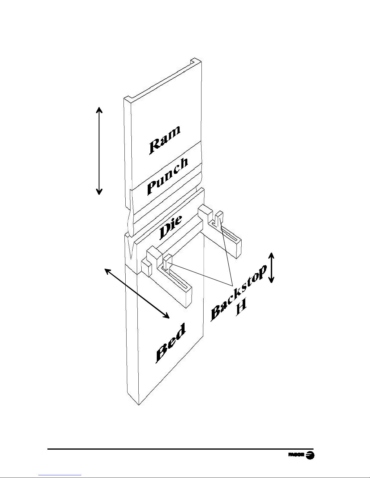
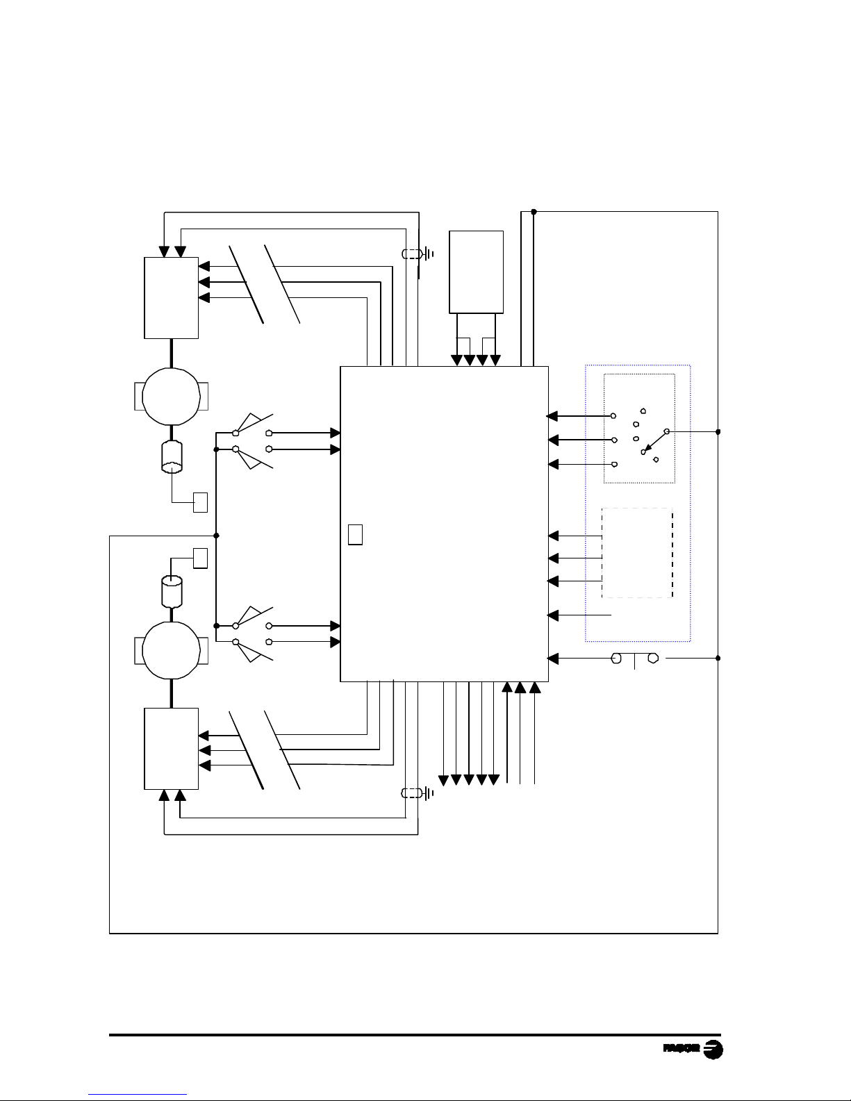
DIAGRAM OF A TYPICAL PRESS BRAKE
Y
X
+
-
-
+
Page 11
NC-200 PB - Installation Manual - Page: 11
1. UNIT DESCRIPTION
This unit is especially designed to be used on punch presses. It allows displaying
the position of the X and Y axes, controlling them as well as the raising device
(H), editing and executing part programs etc. The axes may also be moved
manually from the dro keyboard or externally with footswitches.
1.1 FRONT PANEL (SEE OPERATION MANUAL)
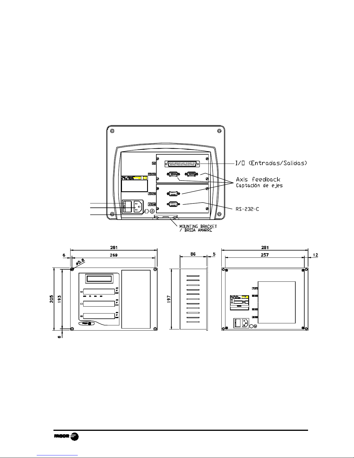
1.2 REAR PANEL
Dimensions of the Built-in model (in mm):
On the back of the unit, the following items may be found:
1.- Power switch.
2.- Three-prong power connector for AC and ground connection.
3.- M6 mm terminal for general machine ground connection.
2
1
3
Page 12
Page: 12 - Installation Manual - NC-200 PB
X2.- SUB-D type 37 pin female connector to connect the digital inputs and
outputs as well as the analog outputs.
X3.- SUB-D HD type 15-pin female connector for X axis feedback device.
X4.- SUB-D HD type 15-pin female connector for Y axis feedback device.
X5.- SUB-D HD type 15-pin female connector for 2nd axis feedback device.
auxiliary Y' axis (only on model "B").
X7.- SUB-D type 9 pin male connector for the RS-232-C serial line connection.
WARNING
Do not handle the connectors while the unit is under power.
Before handling the connectors (mains, feedback, etc.) make
sure that the unit is not under power.
It is NOT enough to turn the display off by using the key
at the keyboard.
1.3 GENERAL TECHNICAL CHARACTERISTICS
Universal Power Supply between 100V AC and 240V AC ±10% at a mains
frequency between 45 Hz and 400Hz, between 120Vdc and 300Vdc
Mains frequency of 0 Hz (DC) and from 45 Hz to 400 Hz.
Power outages of up to 20 milliseconds.
10-year memory backup of installation parameter even when the unit is off.
The operating temperature inside the DRO enclosure must be between 5º C and
45º C (41ºF and 113ºF).
The storage temperature inside the DRO enclosure must be -25º C and +70º C
(-13º F and 158º F).
Maximum relative humidity: 95% non condensing at 45ºC (113ºF).
Front Panel Sealing: IP54 (DIN 40050), Rear panel: IP4X (DIN40050) except
for built-in models in which case is: IP20.
Page 13
NC-200 PB - Installation Manual - Page: 13
2. CONNECTIONS AND CHARACTERISTICS
The connection for the RS-232 serial line (optional X1 connector) is not
described in this manual; but in a supplement for it.
2.1 CONNECTION OF THE FEEDBACK SYSTEMS
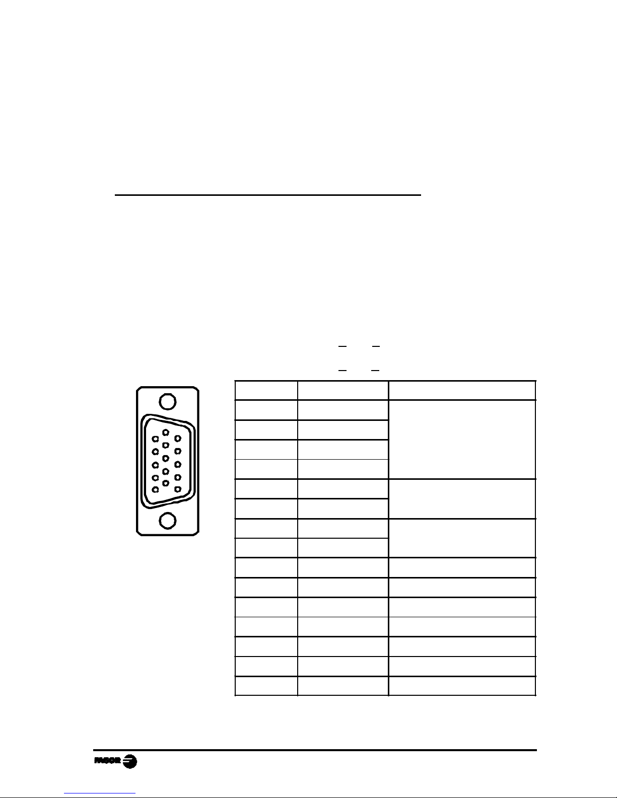
The feedback systems (scales or encoders) are connected via SUB-D HD type
15-pin female connectors: X3 and X4.
Characteristics of feedback inputs: X3, X4 and X5:
- +5V input consumption: 250 mA
- Admits square-wave signal (TTL). (A, B, Io)
- Maximum frequency: 250 KHz,
minimum separation between flanks: 950 nsec.
- Phase shift 90º ±20º, hysteresis 0.25 V, Vmax 7V,
maximum input current: 3 mA.
- High threshold (logic state 1) 2.4V < VIH < 5V
- Low threshold (logic state 0) 0.0V < VIL < 0.8V
* They depend on the type of feedback and may not be connected
1
Pin Signal Function
1 A
Feedback signals
2 /A *
3 B
4 /B *
5 Io
Reference signal
6 /Io *
7 Alarm
Feedback alarm
8 /Alarm *
9 +5V Power for feedback
10 Not connected Not being used at this time
11 0V Power for feedback
12 Not connected Not being used at this time
13 Not connected Not being used at this time
14 Not connected Not being used at this time
15 Chassis Shield
Page 14

Page: 14 - Installation Manual - NC-200 PB
2.2 INPUT/OUTPUT CHARACTERISTICS (X2)
A 37-pin female connector is used.
Signal characteristics of connector "X2":
The supply voltage is at +24V (±25%), thus the threshold
between a "0" and a "1" will be about +6V.
Characteristics of the inputs at 24V :
- Maximum load current: 100mA
- Minimum DC voltage: 18V
- Maximum DC voltage: 30V
The main characteristics of the digital outputs are:
(optocoupled with solid state relay with a normally open
contact)
- Maximum AC or DC voltage: 48V
- Maximum load current: 150 mA
- Maximum internal resistance: 24Ohm
- Maximum peak current: 500mA for 100ms
at 25ºC
- Through current when open: ≤ 1µA
- Leak current: 200nA (Vload=100V)
- Galvanic isolation voltage: 1500V for 1 minute
- Activation time: ≤ 3ms
- Deactivation time: ≤ 3ms
Main characteristics of the analog outputs
Voltage range: ±10V Resolution: 4.88mV
Maximum current: 10mA Offset: ±30mV
Impedance: 120 Ohm referred to GND
Page 15

NC-200 PB - Installation Manual - Page: 15
2.3 INPUT/OUTPUT CONNECTION (X2).
2.3.1 INPUT DESCRIPTION.
Section 2.3.3 shows the electrical diagrams for the indicated models. The
parameters mentioned there are described in chapter 3 of this manual.
The inputs are active high at 24V (PAR21 and PAR22 = 1....1).
Pin 18 may be configured as an analog input with a 0V to +10V range. When
installing a linear potentiometer, it should be supplied with the 5V from the digital
feedback devices (pin 5 of X3, X4).
Pin I/O Common signals Model "A" Model "A1" Model "B" Model "C"
1 Chassis
2 I 0V External
3 I 24V External
4 O 24V User
5 O X enable
6 O 1 = X fast, 0 = X slow
7 O X direction
8 I Not being used
9 O Fast approach Buzzer
10 O Height H, 1 = up
11 I X limit + (Io X)
12 I X- limit
13 I
14 I BCD 1 switch
15 I
16 I External key 1 External key
17 Chassis
Pressure or scale input
X analog output
19 I/O 0V Analog.
20 I 0V External
21 I 24V External
22 O 24V User
23 I Emergency
24 O Y enable
25 O 1 = Y fast, 0 = Y slow
26 O Y direction
27 O Manual mode
28 O Not used
29 O X, Y in position Feed ram Bend slowly Not used
30 I Y limit + (Io Y)
31 I Y- limit
32 I X forward Not used
33 I BCD 2 switch
Y disable
Semiautomatic
35 I External key
36 I External key
37 O Y analog voltage
RETURN footswitch
Ram retract
X forward / retract
BEND footswitch
"BCD 1" EXECUTION mode
Buzzer
New block
Not being used
Presostat
Manual station
"BCD 2" EXECUTION mode selector
18 I/O
34 I
Page 16
Page: 16 - Installation Manual - NC-200 PB
PIN FUNCTION
Models A1, B and C 36 16
1 - RUN 1 0 0
2 - RUN 2 0 1
3 - SET 1 0
4 - JOG 1 1
Model A
External key
simulation. PAR 31
Model A1, B and C
footswitch connection
Models A, A1
Next block
Models A, A1
Double function
F1 + F2
Model A, A1
Mode B, C
The change to SLOW is forced at a previous programmable position
DESCRIPTION
32
15
Not connected. if the machine does not have a pressure sensor.
Pressure sensor
section 2.3.4
FAST approach before the bend conditioned to the maneouver safety
that requires "busy hands".
Model B
A - Electrical signal from the pressure sensor
Allows duplicating any 3 keys that may be selected - PAR 31
35, 36,
16
F2 - Forced X axis feed at the beginning of the bending sequence if
PAR65.2 = 1
8, 35 They respond according to the logic defined with the "BCD" selector
Confirmation of RAM at top dead position. Make sure that I13=1 to
begin the home search (A, A1, B)
If PAR65.1=1, requires previous input at I32
A1 - Confirmation that the programmed maximum pressure has been
exceeded to begin the delay "D".
13
F1 - Retracts the backstop X if there 's a conflict when bending,
conditioned by the editing attribute B in the slow speed stage
The X backstop automatically retracts at the position:
Y = sheet thickness
Only F2
Disables the axes
Disables the outputs
11, 12,
30, 31
Limit switches.
Hardware
23
EXTERNAL
EMERGENCY
In MANUAL mode, they limit the movement in the corresponding
direction.
In EXECUTION mode, they abort the program.
In HOME SEARCH mode, they respond as home switches in the
positive direction
"BCD" selector
36, 16
Displays error 20
2, 3, 4 - Incremental feed with the pitch set by PAR 32
1 - Continuous feed
14, 33,
34
5-position BCD
selector in MANUAL
mode - PAR32
5 - Y axis disable in EDITOR / TEACH-IN mode. It only displays it. It
allows withdrawing the punch by external means in "C" mode.
Semiautomatic in EXECUTION mode
Page 17
NC-200 PB - Installation Manual - Page: 17
2.3.2 OUTPUT DESCRIPTION
If any of the outputs is going to be connected to some highly inductive device,
a "1N4000" type diode must be installed in antiparallel. It is not required on
auxiliary relays of less than 20 mA.
The drives are enabled with auxiliary relays (section 5.2).
PIN FUNCTION
5, 6, 7,
24, 25, 26
Axis enable
FAST/SLOW
DIRECTION PAR46
27 MANUAL mode
10 H output
Models A, A1, B
Ram retraction.
Section 2.3.4
Model A
Axes in position
Model A1
Approach and
bending
Model B
Model B
Model A, A1, C
DESCRIPTION
Analog voltage
outputs. PAR 64,
PAR65
18, 37
It activates the auxiliary output to raise the X axis backstop. R
axis function, ON /OFF conditioned by the "H" editing attribute.
Enabling drives or frequency inverters for open loop control.
To control drives in closed loop drives.
When installing a pressure transducer or potentiometric scale,
connect it to pin 18 and change the position of the internal
jumper.
MANUAL mode selection confirmation.
SLOW approach.
Section 2.3.4
A - Retraction control by trigger time of the thermostat
conditioned by the "D" attribute.
Single output.
The FAST/SLOW change is handled with external resources
from the electrical cabinet that manages the FAST buttons and
the change switch.
I15 when exceeding the bending pressure
29
9
I32 (A, A1) or Y = e (B, C) at the beginning of the bend if
attribute B
A1, B - Forced retraction up to the top dead point. Bending time
conditioned by the "D" attribute.
28
At all models, it is reset with :
It resets in the programmable change position that forces the
slow motion output O29.
Fast movement
handling. Ram
approach.
Buzzer to warn the operator about "permission to bend"
Signal to the electrical cabinet to enable the FAST approach
buttons or SLOW bend footswitch.
Page 18
Page: 18 - Installation Manual - NC-200 PB
2.3.3 INPUT/OUTPUT CONNECTION
2.3.3.1 INPUT/OUTPUT CONNECTION. MODEL A
Without footswitch connection or ram controlling outputs.
M
Encoder
24V
EXTERNAL
MOTOR
CONTROL
21
3
20
2
4
22
EXTERNAL
KEY
SIMULATION
18
27
NC- 200 PB
ANALOG X
GNDA
EMERGENCY
0V
24V
24V USER
X ENABLE
X SPEED
X DIRECTION
M
Encoder
MOTOR
CONTROL
ANALOG Y
GNDA
Y ENABLE
Y SPEED
Y DIRECTION
8
35
23 14 33
7
6
5
19
37
26
25
24
31301211
LIMIT YLIMIT Y+
LIMIT X+
LIMIT X-
x1
x50
x100
Y Dis.
ß
10
13
32
29
MANUAL
H AXIS
IN POSITION
NEXT BLOCK
FEED/RETRACT X AXIS
19
36
28
RETRACT RAM
34
Semiauto
BUZZER
9
Interface
15
PRESSURE SENSOR
16
FREE
BCD
X2
X3 X4
Page 19

NC-200 PB - Installation Manual - Page: 19
2.3.3.2 INPUT/OUTPUT CONNECTION. MODEL A1
With footswitch connection. Manual control and ram controlling outputs.
M
Encoder
24V
EXTERNAL
MOTOR
CONTROL
21
3
20
2
4
22
18
27
NC- 200 PB
ANALOG X
GNDA
EMERGENCY
0V
24V
24V USER
X ENABLE
X SPEED
X DIRECTION
M
Encoder
MOTOR
CONTROL
ANALOG Y
GNDA
Y ENABLE
Y SPEED
Y DIRECTION
23 14 33
7
6
5
19
37
26
25
24
31301211
LIMIT YLIMIT Y+
LIMIT X+
LIMIT X-
x1
x50 x100
Y Dis.
ß
10
13
32
29
MANUAL
H AXIS
FEED RAM
NEXT BLOCK
FEED/RETRACT X AXIS
19
28
RETRACT RAM
34
Semiauto
BUZZER
9
Interface
15
PRESSURE SENSOR
BCD
8
35 36
16
"RETRACT" FOOTSWITCH
"BEND" FOOTSWITCH
RUN 1
RUN 2 SET
JOG
"BCD"
X2
X3
X4
Page 20

Page: 20 - Installation Manual - NC-200 PB
2.3.3.3 INPUT/OUTPUT CONNECTION. MODEL B
With footswitch connection. Manual control and ram controlling outputs.
M
Encoder
24V
EXTERNAL
MOTOR
CONTROL
21
3
20
2
4
22
18
27
NC- 200 PB
ANALOG X
GNDA
EMERGENCY
0V
24V
24V USER
X ENABLE
X SPEED
X DIRECTION
M
Encoder
MOTOR
CONTROL
ANALOG Y
GNDA
Y ENABLE
Y SPEED
Y DIRECTION
23 14 33
7
6
5
19
37
26
25
24
31301211
LIMIT YLIMIT Y+
LIMIT X+
LIMIT X-
x1
x50 x100
Y Dis.
ß
10
13
32
29
MANUAL
H AXIS
RAM SLOW
TABLE TRAVEL LIMIT
FEED X AXIS
19
28
RETRACT RAM
34
Semiauto
RAM FAST
9
Interface
15
MANUAL STATION
FAST FEED
BCD
8
35 36
16
"RETRACT" FOOTSWITCH
"BEND" FOOTSWITCH
RUN 1
RUN 2 SET
JOG
"BCD"
X2
X3 X4X5
Page 21

NC-200 PB - Installation Manual - Page: 21
2.3.3.4 INPUT/OUTPUT CONNECTION. MODEL C
With footswitch connection and manual control.
M
Encoder
24V
EXTERNAL
MOTOR
CONTROL
21
3
20
2
4
22
18
NC- 200 PB
ANALOG X
GNDA
EMERGENCY
0V
24V
24V USER
X ENABLE
X SPEED
X DIRECTION
M
Encoder
MOTOR
CONTROL
VALVE
ANALOG Y
GNDA
Y ENABLE
Y SPEED
Y DIRECTION
23 14 33
7
6
5
19
37
26
25
24
31301211
LIMIT YLIMIT Y+
LIMIT X+
LIMIT X-
x1
x50 x100
Y Dis.
ß
MANUAL
H AXIS
BUZZER
FREE
19
34
Semiauto
Interface
MANUAL STATION
FAST FEED
BCD
8
35 36
16
"RETRACT" FOOTSWITCH
"BEND" FOOTSWITCH
RUN 1
RUN 2 SET
JOG
"BCD"
27
10
13
32
29
28
9
15
FREE
FREE
FREE
X2
X3
X4
Page 22

Page: 22 - Installation Manual - NC-200 PB
2.3.4 BLOCK CHANGE SYNCHRONISM. MODELS A, A1
Description of the diagrams according to positions a, b and c.
There are three ways to synchronize when going from one block to the next at
the end of a bend. If a pressure gage (transducer) is installed, P64.6 = 1, the
editor offers the possibility to program the work pressure on the header page
N0.
1. With the transducer connected to input I18 (P64.7=0), this positioning dro
(NC) compares the active pressure with the one programmed and provokes
the block changing sequence.
2. If the comparator is external (P64.7=1), this positioning dro (NC) waits for
a signal at I15 that confirms that the programmed pressure has been exceeded
in order to begin the change sequence.
In either case:
a. Output O29 is deactivated (INPOS) in order to prevent the ram from going
down.
It starts the delay "D", bending time, at maximum programmed pressure.
b. At the end of the bend, output O28 is activated to force the ram to return
automatically and it resets the analog output for pressure.
c. When it reaches the top dead point I13=1, it resets O28 and goes on to the
next block. If PAR65.1=1, it requires a flank at I32 to confirm the contact
of the punch with the sheet.
3. With pressure sensor signal, P64.6=0, connected to I15 and programmable
delay for RAM UP.
When the pressure sensor triggers:
a. It deactivates O29 (INPOS) to prevent the ram from going down.
It activates O28 to force the ram to return automatically. It is affected by
the timer (PAR29 + D). As a precaution, a minimum delay is forced
(PAR29).
b. It resets O28 and it goes on to the next block.
There are three possibilities:
b1 With a "D" value too high, the ram reaches the top dead point, it
activates I13 before the delay is over.
b2 If D = 0, after the PAR29 delay.
b3 If the delay is over (PAR29 + D), it forces it to go to the next block
without waiting for I13.
In the "b1" and "b2" modes, I13 resets the timer and O28.
If it reaches the top dead point, it goes on to the next block.
If PAR65.1=1, it requires a previous flank at I32.
Page 23

NC-200 PB - Installation Manual - Page: 23
I18
CHANGE I13
BLOCK
Analog Input
(A) IN_POS O29
BEND
RETURN O28
1- Pressure analog input
Par64 (6) = 1
Par64 (7) = 0
cba
I18
CHANGE I13
BLOCK
Analog Output
(A) IN_POS O29
BEND
RETURN O28
2- Pressure analog output
I15
Pressure level
Par64 (6) = 1
Par64 (7) = 1
abc
BLOCK I13
CHANGE
(A) IN_POS O29
BEND
RETURN O28
I15
Pressure level
Block change
3- Pressure gage input
Par64 (6) = 0
a
b1b2b1
b3
Page 24

Page: 24 - Installation Manual - NC-200 PB
2.3.5 BLOCK CHANGE SYNCHRONISM. MODEL B
Description of the diagram according to positions 1 through 6:
1. With X and Y axis already in position, the FAST approach is activated from
the MANUAL control station IE15 or only SLOW from the "BEND"
footswitch (I8).
2. In the change position, Y= PAR33 or programmable, the SLOW speed is
activated with the "BEND" footswitch.
3. When pinching the sheet metal, Y = thickness, it resets O29 to wait for the
return of the X axis.
4. Once the programmed bending depth has been reached, the auxiliary
feedback Y compares the difference Y -Y' < PAR18 to begin the bending
delay, "D" attribute.
5. After the delay "D" and depending on the selected cycle, it activates the
return:
If RUN1, RUN2 - Automatic or when interrupting with I35.
If SET- With return footswitch I35.
6. When reaching the final dead point, PAR28 or programmable, it begins the
next block.
Page 25

NC-200 PB - Installation Manual - Page: 25
- Position
Y' - Auxiliary scale
PAR33
Programmed Y coordinate
Y' = e
FAST/SLOW
change
Programmable
top dead point
By default: PAR28
SLOW
O29
programmable
By default: P29
D
·I8·I8 I8
FAST
09
Retract X
·I15
RAM DOWN
O28
MANUAL-SET
·I35 JOG
BEND
footswitch
I35 in EXEC.
RUN1, RUN2
1 2 3 4 5 6
X, Y axes IN POSITION. To enable O29, O9 O28
MANUAL CONTROL
STATION I15
Begin bend
FOOT CONTROL
STATION, BEND I8
STOP
Cut off valve
Sheet pinched
FOOT
CONTROL
STATION
E35
Fina
bend
position
X + Y in
motion
·I8
Page 26

Page: 26 - Installation Manual - NC-200 PB
2.4 MACHINE REFERENCE (HOME) SEARCH
In this mode, the initial values are preset in a fixed reference position.
If PAR14.4 = 1 on any axis, home search is mandatory on that axis every time
the machine is turned on.
This unit starts in mode.
To quit this mode without homing, press and key in the access/exit code:
719200
If PAR14.4 = 0, home search is only required on machine setup. At the beginning,
the software limits PAR12 and PAR13 should be opened to their maximum
values to prevent this NC from forcing uncontrolled movements in order to
position the axes within these travel limits.
Should this happen by mistake, the movement may be stopped by pressing .
Being PAR14.1 = 1 (Floating home search), if while in this state you press
[access code], the affected axis will show the value: PAR12 + PAR26 as initial
value. When pressing the relevant key , , it will suggest the PAR10 value
by default with an option to select any other as described in later chapters.
2.4.1 X AXIS HOME SEARCH
PAR14 establishes how the machine reference (home) search is to be carried out.
All models perform this home search in the positive direction.
The X axis usually has a travel limit switch: PAR 14 bit 1 = 0 and a rotary encoder.
The home searching sequence is as follows:
· Set the NC in Home search mode by pressing .
The led will turn on.
If the home search for any of the axes is defined as "floating"
(P14.1 = 1), it requests the password (719200) after pressing .
· Select the axis. The unit will display the text "START".
· Press .
The Axis moves in the positive direction, backwards, in rapid until reaching the
positive travel limit switch.
Once the switch is pressed, it returns at slow speed until the reference mark (I0)
of the rotary encoder is detected. At that point, this unit displays the value set
at PAR10 (that will correspond to the real value from the center of the die to the
support side of the X axis). See section 2.4.5
Page 27

NC-200 PB - Installation Manual - Page: 27
2.4.2 Y AXIS REFERENCE (HOME) SEARCH. MODELS A AND A1
a- If the machine has travel limit switches, the home search procedure is the
same as the one described for the X axis; but it is only enabled if I13 = 1,
ram at top dead position.
b- If the machine does NOT have travel limit switches (which is very common
on down stroke models), set PAR14 bit 1 = 1 to indicate that the reference
position is floating.
The homing sequence is as follows:
· In MANUAL mode, move the Y axis in the Y+ direction to make sure that
the backlash is properly compensated for.
If P17 = 1, the Y- movement will be affected by the unidirectional approach
and will return in the Y+ direction.
· Press the "BEND" footswitch until the ram reaches its final position. Output
O27 is active ("A" model) to enable the footswitch.
· Measure the distance between the support bases of the punch and die.
This distance will be the Yref to be preset.
· Press . The led will turn on. Enter the password (719200).
This unit displays the real position and the axis remains on stand by.
· Select the axis, (by default, it suggests the PAR10 value) and preset the
reference value Yref and press to assume it. It displays the coordinate
( Y = Yref - Hpunch - Hdie) compensating the height of the tools that are active.
See section 2.4.5
Page 28

Page: 28 - Installation Manual - NC-200 PB
2.4.3 Y AXIS HOME SEARCH. MODEL "B"
Usually, this axis has home switches on UP-STROKE models.
· Position the table or the ram at the far-end position activating the limit switch
I13.
· Press . The led turns on.
· Select the axis. It displays the word "START".
· Press to reach the home position.
· Actuate on the "BEND" footswitch until the punch or the die (on up-stroke
models) goes to its final position.
a) With a linear encoder:
· Press to synchronize the Y axis home value set in PAR10 with that
of its associated axis Y'.
b) With a linear potentiometer:
It requires two synchronization points for the value of the Y axis with the
position of the table in order to obtain the V/mm constant of the
potentiometer and set an initial reference value.
1- Pressr , it displays the value of the potentiometer cursor in volts.
It enables the MANUAL mode.
2- Press
3- Use to move the Y axis to the far-end position towards Y-.
Activate the BEND footswitch again until the final position.
Press again.
Quit by pressing
Page 29

NC-200 PB - Installation Manual - Page: 29
2.4.4 Y AXIS HOME SEARCH. MODEL "C"
An up-stroke or down-stroke model "C" has a linear encoder and controls the
actual (real) position of the ram using foot switches. It usually has travel limit
switches.
If PAR00 bit 6 = 0, has been set for a linear encoder with a regular reference
mark (without distance-coded reference marks), the homing procedure is the
same as described in section 2.4.2 (a)
If PAR00 bit 6 = 1 has been set for a linear encoder with distance-coded reference
marks.
The homing sequence is as follows
· Set the NC in Home search mode by pressing .
The led will turn on.
· Select the axis. The unit will display the text "START".
· Press .
The axis moves upwards in the positive direction until detecting two consecutive
reference marks (I0's) and it displays the reference value set at PAR10.
PAR10 = D - O + ε
Where D = Distance between the support bases between the punch and the die.
O = Offset value indicated on the label of the linear encoder
ε = (See the next section 2.4.4)
Page 30

Page: 30 - Installation Manual - NC-200 PB
2.4.5 PRECAUTIONS WHEN HOME SEARCHING
The software limits set by PAR12 and PAR13 will indicate the real values referred
to machine zero and they will correspond to the + and - limits slightly short of
the positions of the travel limit switches or hard stops.
The floating-home search on the Y axis (PAR14.1 = 1) is a little risky if the home
value is wrong and does not match the actual distance between the supporting
sides of the punch and die. The software limits set by the OEM may be overshot.
The Y axis tries to recover a position within the software limits with the risk of
exceeding the limits of the worm gear mechanism.
As a precaution, make sure that the ram is in the upper area (I13 = 1) to make
the home search sequence possible.
If the machine has home switches (PAR14.1 = 0), the contact point of the microswitch with the cam should not be too close to the position of the first reference
mark (I0) of the encoder. The + limit switch is also the reference input that is
deactivated when reversing the movement direction. A certain margin should be
kept in order to reach a stable slow feedrate before receiving the reference mark
(I0) also overshooting the amount of backlash set at PAR16. Standard clamps
allow some rotation of the encoder body to make this adjustment easily.
Once the home search is finished, the axis moves towards X- until it reaches the
software travel limit (always less than the hardware limit set by the X+ home
switch) until reaching the position = PAR13 - PAR26.
On open-loop controls, the I0 signal sends a stop command; but there is no
assurance that the axis will be held at that position. There is a slight overshooting
even when selecting a slow home search speed.
Selecting the reference value for PAR10 takes three steps:
1- Set PAR10 with any value and execute a home search for a first rough
approach.
Calculate the "ε" difference: ε = PAR10 - final position reached (+ value)
2- The final value for PAR10 will be: The requested distance between the
support bases between the punch and the die + ε.
3- Set the software travel limits PAR12 and PAR13.
Page 31

NC-200 PB - Installation Manual - Page: 31
2.5 RS-232-C CONNECTION (CONNECTOR X7)
The RS-232-C serial communications line uses a 9-pin male SUB-D type
connector.
Parameter PAR90 sets the transmission speed through this line. See section 3.5 in
this manual.
The operating mode for this feature is described in chapter 5 of the Operating
Manual.
Pin Signal Function
1 NC Not connected
2 RxD Receive Data
3 TxD Transmit Data
4 NC Not connected
5 GND Ground
6-9 NC Not connected
Page 32

Page: 32 - Installation Manual - NC-200 PB
2.6 POWER AND MACHINE CONNECTION
This NC can be connected to an AC voltage anywhere between 100V AC and 264 V AC
±10% at a frequency between 45 Hz and 400 Hz. Between 120Vdc and 300Vdc without
having to select it depending on the country where they are installed thanks to their
universal power supply.
Always mount it vertically so its keyboard is within operator's reach and its digits are
easily visible (at operator's eye level).
Do not connect or disconnect this NC connectors while it is under power.
Connect all metallic parts to a common point on the machine tool and it to the general
ground point. Use cables of enough gage (no thinner than 8 mm2).
2.7 TURNING THE UNIT ON AND OFF
Turning the unit ON
The unit is turned on by actuating on the power switch of the rear panel
This NC runs a self-test and shows on the LCD display the text: “Fagor NC-200PB, Press
and the and displays show "Fagor dro" if everything is OK and the error
number if otherwise. See the appendix at the end of this manual.
Turning the unit OFF
If you press this NC turns off the displays while maintaining the power supply to
the feedback systems and goes on reading the position of the axes at all times. This is
not the case when the equipment is switched off by means of the switch on its rear
panel.
To reset the displays, just press this basta again, as long as this NC is getting
voltage (plugged in and with the switch on the rear panel on).
Notes:
- Before powering this NC down with the switch on the rear panel or disconnecting it
from mains, it is a good idea to press the key in order to store the current
position of the axes permanently.
- If the unit is powered down with its rear panel switch or there is a power outage without
previously having pressed , this NC will keep the last position of the axes for at
least 30 minutes.
- The unit will display ERROR 2 when powered back up if the position reading was lost
when turned off while the axes were moving or after the accidental backup period has
expired without having saved the current position by previously pressing
.
Page 33

NC-200 PB - Installation Manual - Page: 33
3. INSTALLATION PARAMETERS
These NC's have a number of installation parameters to configure it for a
particular application.
These parameters may be saved into a peripheral or uploaded from it through
the RS-232-C serial communications line.
The format for these parameters depends on whether they are general or
particular for each axis.
. If it affects the axes, press the corresponding axis key to modify it.
. If it is a general parameter, the X display will show its current value.
. The LCD display will show the description of the parameter and its number.
There are several kinds of parameters depending on how to set them:
· Binary values (1/0) are displayed in an 8-digit row identified as 1 through 8
from right to left.
Their state changes by pressing their associated number key
1
to
8
.
· With decimal values, select the axis and key in the value.
· Options, the value is selected by pressing
-
+
which will show the various options
in a rollover way.
· Simulated key code, by accessing the corresponding key.
Page 34

Page: 34 - Installation Manual - NC-200 PB
3.1 PARAMETER SETTING
Machine parameters PAR50, PAR51 and PAR90 enable special features of this NC.
The user may access them directly.
In initial mode, press [parameter number] .
The rest can only be accessed by installers and technicians.
Press and hold for at least 2 seconds, when the displays start blinking,
press .
Key in the access code: 060496 to access the general parameters.
Once on the menu, to access a particular parameter, press:
[Parameter number]
The LCD display will shows the parameter number and a short description.
. If it is a general parameter, its value is only shown on the first display.
. If it is an axis parameter, each axis display will show its current value.
In this case, select the axis by pressing its key ( or ) and key in its
new value.
- To go to the next parameter saving the changes:
Press or to go to the next one.
To return to the previous one, press
- Pressing the key of the other axis ( or ) saves the value of the previous
axis and it goes on to edit the new selected axis.
- Pressing will quit the parameter editing mode.
- If while changing the value of a parameter, is pressed, the unit will ignore
the new value and will assume the previous one.
Page 35

NC-200 PB - Installation Manual - Page: 35
Binary values (1/0) are displayed in an 8-digit row identified as 1 through 8 from right
to left.
X X X X X X X X
8 7 6 5 4 3 2 1
PARAMETER FUNCTION
PAR00 Feedback configuration, different per axis. Binary type.
This parameter sets the specific characteristics of the feedback
device (rotary or linear encoder) used to read the axis position.
Digit
8 Direction of the distance-coded Io (0 = Increasing, 1 = Decreasing)
Fagor offers two types of linear encoders depending on the type of
reference marks they use (Io): the standard one with several reference
marks every 50 mm and the one with distance-coded reference marks
(models with "O", e.g.: MOVX, FOP, etc.).
When using a rotary encoder or a standard Fagor linear encoder
(without "O") for this axis, this bit must be set to "0".
When using an "M" or "F" series Fagor linear encoders with
distance-coded reference marks (e.g.: MOVX, FOP) for this
axis, this bit must be set to "0".
When using a "C" type linear encoder with distance-coded reference
marks, (e.g.: COX, COVP) for this axis, this bit must be set to "1".
7 Pitch of the distance-coded Io (0 = 20 mm, 1 = 100 mm)
This bit is ignored if bit 6 has been set to "0".
When using Fagor M or C series linear encoders, this bit must be "0".
When using Fagor F series linear encoders, this bit must be "1".
6 Type of linear scale's Io (0 = Fix, 1 = Coded)
Fagor offers two types of linear encoders depending on the type of
reference marks they use (Io): the standard one with several reference
marks every 50 mm and the one with distance-coded reference marks
(models with "O" e.g.: MOVC, COS, etc.).
When using a rotary encoder or a standard Fagor linear encoder, this
bit must be set to "0".
Page 36

Page: 36 - Installation Manual - NC-200 PB
5 Axis units: 0 = mm, 1 = inches
These units refer to the feedback and not to the display which may
be changed with the key..
4 Not being used at this time. It must be set to "0"
3 Not being used at this time. It must be set to "0"
2 Type of feedback signals (0 = TTL)
This bit must be set to "0". A value of "1" will be ignored.
1 Counting direction (0 = normal, 1 = reverse)
Regulation for press brakes:
X axis retraction in the positive direction.
Ram up movement in the positive direction.
If an axis count increases or decreases in the opposite direction to the
one desired, change the value of this digit. It conditions the setting of
the sign bit PAR46(2) and the sign of the analog voltage.
PAR01 Feedback resolution, independent for each axis,
Possible values: from 0.0001 mm to 1 mm.
From 0.000001 to 0.03937 inch
factory setting: 0.0050 (mm).
PAR02 TTL multiplying factor (subdivision). Independent for each axis.
Options: x4, x2, x1 and x0.5.
The selection of these values rotates by pressing
The factory setting is: x4 and it is the one used for FAGOR scales.
When using an encoder, its number of pulses should be calculated
according to the leadscrew pitch, the desired resolution and the
multiplying factor to be applied as per the formula:
Encoder (lines/turn) = Leadscrew pitch (mm/turn)
Resolution (mm/pulse) x F
Where "xF" would be the multiplying factor to be applied.
Page 37

NC-200 PB - Installation Manual - Page: 37
PAR03 External multiplying factor (EX E type) when using linear encoders
with distance-coded reference marks and TTL feedback signals.
Independent for each axis.
Options: 1, 5, 10, 20, 25, 50. Factory setting: 1
These values are selected by pressing
For example:
For standard Fagor linear encoders with squarewave signals (without
"O" or "P") e.g.: MX, CT, CX, etc. it must be set to "1".
For Fagor linear encoders with squarewave signals and distance-
coded reference marks (models with "O"), eg.: MOX, COX, etc.
it must be set to "5".
For Fagor linear encoders with squarewave signals and distance-
coded reference marks (models with "O") and 0.5µm resolution,
eg.: MOY, COY, etc. it must be set to "10".
PAR05 Resolution (PAR01) correction factor.
It may be used for adapting any resolution, even fractional, when
the encoder is affected by a mechanical gear reduction.
PAR08 Feedback alarm enable. On if = 1 and Off if = 0.
Digit
3 Detects the feedback alarm provided by the encoder through pins
7 and 8.
Fagor models DO NOT provide this signal.
rest Not being used at this time. They must be set to "0".
Page 38

Page: 38 - Installation Manual - NC-200 PB
PAR10 Absolute value set on each axis at the end of the home search.
On press brakes, it coincides with (see section 2.4):
On the X axis:the distance from the center of the die to the support
side of the X carriage.
On the Y axis:The distance between the support sides of the punch
and the die.
Factory setting: 0.
This value will be in mm or inches depending on whether the INCH
LED is off or on.
PAR12 To set the minimum axis travel limit.
Possible values: within ±99999.999
This value will be in mm or inches depending on whether the INCH
LED is off or on.
If PAR08(2)=1 (limit alarms ON), when the axis exceeds this
distance, the corresponding axis display starts blinking until it is
moved back into the work zone.
PAR13 To set the maximum axis travel limit.
Possible values: within ±99999.999
This value will be in mm or inches depending on whether the INCH
LED is off or on.
If PAR08(2)=1 (limit alarms ON), when the axis exceeds this
distance, the corresponding axis display starts blinking until it is
moved back into the work zone.
PAR 14 It sets how the machine reference search (I0) will be carried out .
Digit
8, 7, 6, 5 Not being used at this time. They must be set to "0".
4 If =1, mandatory home search on power-up.
3 If =1, The whole home search is carried out at slow speed.
2 It does not use a home switch.
Home search begins slowly in the negative direction. It ends when
detecting the 1st marker pulse (home signal) of the encoder.
Page 39

NC-200 PB - Installation Manual - Page: 39
1 If = 0, The selected axis moves in rapid in the positive direction up tot
home switch and returns at slow speed until detecting the home pulse.
If = 1, the home position is floating.
When pressing , it requests the password (719200).
PAR 16 It sets the value of the leadscrew backlash to compensate for.
Range of possible values: ±99999.999
PAR 17 It sets how the leadscrew backlash compensation will be applied with
unidirectional approach.
0 = There is no unidirectional approach.
X axis: 2 = It will be applied when moving in the positive direction.
Y axis: 1 = It will be applied when moving in the negative direction.
PAR18 It indicates the multiplying factor applied onto leadscrew backlash,
PAR16, in order to calculate the overshooting distance in unidirectional
approach. In order to assure that the return will be done at slow speed,
set P26 > P16 x P18
Possible values: 1 to 255
PAR19 Indicates the reduction factor of the Kv gain. It affects exponentially in
base 2.
For example: PAR19 = 3 means a reduction factor of 23 = 8.
Possible values: between 0 and 20. Recommended value: 10
Positive (X)
+0- +0-
Page 40

Page: 40 - Installation Manual - NC-200 PB
PAR21 Indicates the active level of the first 8 inputs.
By default, they are set to "1" meaning that they are activated with 24V.
Digit Pin
8 33 BCD 2
7 14 BCD
6 32 Retract X axis / Feed in forced mode.
5 13 Go to next block
4 31 Y axis negative travel limit
3 12 X axis negative travel limit
2 30 Y axis positive travel limit
1 11 X axis positive travel limit
PAR22 Indicates the active level of the next 7 inputs.
By default, they are set to "1" meaning that they are activated with 24V.
Digit Pin
8 Not being used at this time. It must be set to "0".
7 23 Emergency
6 8 "Return" foot switch.
5 36 External key 3 (A). EXECUTION mode selector
4 35 External key 2 (A). "BEND" foot switch.
3 16 External key 1 (A). EXECUTION mode selector
2 34 Disable the "Y" axis (Teach-in)
1 15 Hands-on palm switches / pressure level.
PAR23 Indicates the active level of the first 8 outputs.
By default, they are set to "1" meaning that when activated, they
provide 24V.
Digit Pin
8 10 "H" output
7 27 Manual mode active
6 26 "Y" axis moving direction
5 7 "X" axis moving direction
4 25 "Y" axis fast movement
3 6 "X" axis fast movement
2 24 "Y" axis enable
1 5 "X" axis enable
PAR24 Indicates the active level of the next 3 outputs.
By default, they are set to "1".
Digit Pin
8-4 Not being used at this time. They must be set to "0".
3 29 Axes in position (A). RAM down.
2 9 Buzzer. RAPID approach (B)
1 28 Retract RAM.
Page 41

NC-200 PB - Installation Manual - Page: 41
PAR25 In-position zone.
It is the distance before and behind the point where the axis is considered
to have reached its target position.
(Model B). On up-stroke machines, it represents the maximum deviation
allowed between the Y axis position and that of its
associated linear encoder or potentiometer to confirm the
end of the bend.
(See the following time diagram)
Possible values: From 0.0001mm to 99999.999 mm
(From 0.000005" to 3937").
Recommended value: between 0.02 mm and 0.05 mm
PAR26 Indicates the braking distance (slowdown point)
By default, this unit sets P26=P27 if P26<P27
(See the following time diagram)
Possible values: From 0.0001mm to 99999.999 mm
(From 0.000005" to 3937").
Recommended value: between 1 and 5 mm.
PAR27 Indicates the stopping distance (stop offset).
It does not admit PAR27 = 0.
(See time diagram below)
Possible values: From 0.0001mm to 99999.999 mm
(From 0.000005" to 3937").
Recommended value: between > 0 mm and 0.5 mm
The description of Par27 continues on the next page.
PAR27 and PAR47 must be coordinated in order to ensure that the
known final position is within the in-position zone (PAR25). See
chapter 5.
Par27
Par26
Enable
Speed
Fast
Slow
Par25
Page 42

Page: 42 - Installation Manual - NC-200 PB
PAR28 Top dead point. Default value of the relative distance between the punch
and the die to return ram after each bend.
Possible values: From 0.0001mm to 9999.9999 mm
(From 0.000005" to 393.700").
It may be forced from the editor. "B" and "C" models.
PAR29 Default value of the delay of the punch in contact with the sheet metal
at the end of the bend.
Possible values: between 0 seconds to 9.9 seconds.
It may be forced from the editor. It is referred to as the "d" attribute.
PAR30 Default value of the delay applied to the X axis movement before the next
positioning move (only if when moving towards X-).
Possible values: between 0 seconds to 9.9 seconds.
It may be forced from the editor. It is referred to as the "t" attribute.
PAR31 (Model "A"). Configuration of the 3 inputs for external key simulation
through pins 16, 35 and 36 of 37-pin connector X2.
· To assign a key to input I16:
Press and then the key to be assigned.
· To assign a key to input I35:
Press and then the key to be assigned.
· To assign a key to input I36:
Press and then the key to be assigned.
Page 43

NC-200 PB - Installation Manual - Page: 43
PAR32 Configuration of the INCREMENTAL MANUAL SWITCH positions
(pins 14, 33 and 34 of the 37-pin connector X2) to externally select
the jog increments.
Normally, a 5-position BCD switch is used (positions 1 to 5).
Position 1 is used for continuous jog, position 5 to disable the "Y" axis
and to select the semiautomatic mode (pin 34) and the three in between
for incremental movements.
The message screen shows "PAR32.N" where "N" is a value
between 0 and 3 related to the switch dial position.
PAR32.0 is reserved as CONTINUOUS JOG mode. It does not
affect the resolution.
PAR32.1 to PAR32.3 Value of the INCREMENTAL JOG in
multiples of resolution units (according to PAR01).
For example, if the resolution selected in PAR01 is 5 microns and
with the switch set to position 4 the axis is to be moved 500 microns
(0.5 mm) every time are pushed, PAR32.3 must be assigned
the value of 100.
The maximum value is 255 units of resolution.
PAR33 Speed change position. Models B and C.
It sets the relative height between the punch and the top side of the
sheet where the speed is to be changed from fast to slow in the down
stroke. Possible values: From 0 mm to ±99999.999 mm
(From 0" to ±3937").
PAR33 = 0 means that the speed change takes place when the ram
touches the sheet.
SWITCH
POSITION
BCD
VALUE
PIN 14 PIN 33 PIN 34 FUNCTION
1 0 0 0 0 CONTINUOUS JOG
2 1 1 0 0 1st INCREMENTAL POSITION
3 2 0 1 0 2nd INCREMENTAL POSITION
4 3 1 1 0 3rd INCREMENTAL POSITION
5 0 0 1 DISABLE Y / SEMIAUTOMATIC
Cont.
jog
Incr.1
Incr.2
Incr.3
Disable Y
Semiauto
1
2
3
4
5
Page 44

Page: 44 - Installation Manual - NC-200 PB
On the model A. Set the upper negative value for the maximum
bending depth.
PAR35 Indicates the duration of the "in-position" output O29 that enables
the "BEND" foot switch.
Possible values: between 0.1 seconds and 9.9 seconds.
If = 0, the signal stays active until the pressure gage signal is received
at pin 15 of connector X2 or the programmed level is exceeded.
The output is canceled if there is a backwards movement of the X axis
in the bending stage.
PAR36 Configuration of the X axis withdrawal (retract).
0 = Move it in incremental mode in the X+ direction the distance set
by PAR37.
1 = Move it in absolute mode the value set by PAR37 .
PAR37 X axis retraction distance (incremental) or position (absolute) when
activating the I32 signal of the 37-pin connector X2 on Model "A"
or when the punch reaches the "Y=sheet thickness" position on B
and C models.
Possible values: From 0 mm to 99999.999 mm
(From 0" to 3937").
PAR39 Analog voltage centering. Back-and-forth movement for balancing
the sign of the analog voltages.
Measure the analog voltages of this unit in both directions in any of
the ranges (fast or slow). Calculate the difference and divide by two.
Try different values of multiples of 5 mV to obtain the best balance.
For example: 6.135 and -6.120 => (0.015 difference)/2 = 0.007
Round it off to the closest value: 0.005 or 0.010
Page 45

NC-200 PB - Installation Manual - Page: 45
PAR40 Proportional gain Kv of the position loop in the positive direction if
PAR46(5) = 1. Axis controlled in closed loop.
(See section 5.2).
Possible values: Between 0 and 255.
PAR41 Proportional gain Kv of the position loop in the negative direction if
PAR46(5) = 1. Axis controlled in closed loop.
(See section 5.2).
Possible values: Between 0 and 255.
PAR42 Conversion factor of the pressure gage.
Kp = Tons/volt.
Possible values: Between 0 and 99.9
PAR44 Minimum analog voltage set for movements in the positive direction
(only if closed loop). Dynamic improvement with proportional hydraulic
valves that usually require a considerable voltage threshold in order to
allow a linear response.
Possible values: Between 0V and 10V
PAR45 Minimum analog voltage set for movements in the negative direction
(only if closed loop). Dynamic improvement with proportional hydraulic
valves that usually require a considerable voltage threshold in order to
allow a linear response.
Possible values: Between 0V and 10V
PAR46 Axis control.
Digit
8, 7, 6 Not being used at this time. They must be set to "0".
5 If =1, axis controlled in closed loop (the enable is maintained within
the in-position zone
If =0, "Axis controlled in open loop". The enable is canceled when
reaching the in-position zone. It is restored if the axis gets out
of position.
4 Not being used at this time. It must be set to "0".
3 Use analog voltage for feedrate.
2 Sign of the positive movement. Change it if the axis does not get in
position.
1 Bipolar voltage for speed.
Page 46

Page: 46 - Installation Manual - NC-200 PB
PAR47 Analog voltage for slow axis feedrate in the positive direction.
Value range: Between 0 and 10V.
PAR48 Analog voltage for slow axis feedrate in the negative direction.
Value range: Between 0 and 10V.
PAR49 Analog voltage for fast axis feedrate in both directions.
Value range: Between 0 and 10V.
PAR50 Language selection for the messages appearing on the LCD display.
0 = English; 1 = Spanish; 2 = German; 3 = French; 4 = Italian;
5 = Portuguese; 6 = User defined.
PAR51
Digits
8 If =1, the EDITOR no longer shows the "attributes" page for
machines or programs that do not require those resources.
This unit will assume the attribute values set by parameters
PAR29 (d) and PAR30 (t).
7 On "A" and "A1" models with an electrical signal from the pressure gage,
the top dead point may be preset with the "D" variable, timing the ramup movement. Productivity may be improved when dealing with small
parts:
If =1, to activate this feature.
If =0, to deactivate this feature. The block change is only forced when
the ram reaches the top dead point, I13=1.
6 to 3 Not being used at this time. They all must be set to "0".
2 To turn on (=0) or off (=1) the confirmation beep when pressing the
keys.
1 Program memory lock, 0 = unlocked; 1 = locked.
PAR52 Loading of the user defined language.
When accessing this parameter, the NC requests the password.
After keying 5564, the NC is ready to receive the file containing the
user defined language.
Page 47

NC-200 PB - Installation Manual - Page: 47
PAR64 Press brake model definition
digit
8 Not being used at this time. It must be set to "0".
7 If = 0, pin 18 of connector X2 is selected as the analog input for the
PRESSURE/VOLTAGE gage or potentiometric scale.
Both options are incompatible .
This operation requires a position change at the selector installed in
the circuit of connector X2 which is accessed by removing the rear
board: To set pin 18 as analog input, put the jumper towards "U4".
Set PAR46.5 and PAR46.3 to "0" to configure the X axis in open
loop.
If = 1 and jumper towards "U7", it is set as an analog output.
6 Setting of pin 18
If = 0, it is selected as analog output for the X axis.
If = 1, it is selected as an input or output (PAR64.7) for the pressure
gage.
The X axis will be controlled in open loop without using the analog
output PAR46.5 = 0, PAR46.3 = 0.
2 If =0, LCD screen
If =1, VFD screen (blue)
1 Not being used at this time. It must be set to "0".
5 4 3
Press brake
model
Description
0 0 0
A
Only the final bend position is controlled
1 0 0
A1
Same as model A with footswitch handling
0 1 0 B
Same as model A1 with linear encoder for
decoded intermediate ram-bed positions
0 0 1 C
Control of actual ram-bed position with footswitch
and "busy hands" handling.
Page 48

Page: 48 - Installation Manual - NC-200 PB
PAR65 Special configurations.
Digit
8 to 5 Not being used at this time. They must be set to "0".
4 Only for the "B" model.
If = 0, the feedback device for the ram/table position is a linear encoder.
If = 1, the feedback device for the ram/table position is linear potentiometer.
3 Axis positioning mode.
If =0, The axes move at the same time.
If =1, The axes move one after the other (1st X and then Y).
Both axes may be positioned with the same inverter using the relevant
enable signals to toggle the power connection fine tuning the adjustment
of the X axis to avoid rebounds at the final positioning.
2 If = 1, the feed towards "X-" will be forced with I32 (safety regulations
for rapid feed).
Install a push button on the operator panel for starting each bending
sequence when moving towards "X-". I32 is shared with the micro switch
detecting the contact between the punch and sheet metal.
1 If = 1, There is a detector for punch-sheet contact.
Use the "B" attribute to provoque the return of the X axis.
It requires a previous flank at I32 to confirm the change of block with
I13.
If = 0, there is no detector. The "B" attribute is ignored.
If the bending sequence is interrupted and the ram returns to the top dead
position, I13=1, it provoques the uncontrolled block feed.
PAR90 Indicates the transmission speed of the RS 232 line.
Options: 75, 150, 300, 600, 1200, 2400, 4800 & 9600 baud.
Factory setting: 9600 baud
This NC sends and receive data at the speed set by PAR90 and with
the following configuration:
Stop bits: 1
Data bits: 8
Parity: None
Protocol: XON/XOFF
Page 49

NC-200 PB - Installation Manual - Page: 49
4. OPERATION WITH THE RS-232-C SERIAL LINE
4.1. SAVING AND RESTORING DA TA
With this NC, it is possible to save data into a PC or peripheral device and later
restore it by using the RS-232-C serial communications line.
This data is sent out in the following format:
Baudrate as set by PAR90, 8 data bits, 1 stop bit and no parity.
To access this mode:
- Press
F
- Select the "Com" option (communications) of the LCD display by means of
the and press .
- Select: <Send> and press to send the data out to a PC or peripheral
device or select <Receive> and press to receive data from a PC or
peripheral device.
- Select the type of data to transmit Parameters, Program, Materials by means
of the keys and press .
4.2 PARAMETER TRANSMITTING FORMA T
The format of the transmitted parameters are:
For value parameters: P?? 123.123
For binary parameters: P?? 10101010
For option parameters: P?? 0
For axis parameters: P?? X 123.123 Y 123.123
The number of decimals depends on the selected resolution.
Page 50

Page: 50 - Installation Manual - NC-200 PB
5 SETUP
5.1 TEST MODE
A special mode has been created in order to make machine setup easier. This
mode is accessed from the main menu. Special care must be taken since software
and hardware limits are ignored in this mode.
Section 3.1, PAR21 through PAR24 describes the correspondence between the
display digit number and the number of the connector pin to be tested.
· Press F
· Use to select TEST and press .
This unit requests a password to access this mode: 719200
The message display offers four options that may be selected with
INPUT- Testing inputs <In>
· The 1st line shows 0's and 1's indicating the status of inputs I1 through I8
from right to left.
· The 2nd line shows the status of inputs I9 through I15.
OUTPUT- Forcing outputs <out>
Digital outputs
· The 1st line shows 0's and 1's indicating the status of outputs O1 through
O8 from right to left.
The outputs are activated or reset by pressing their relevant key.
1
for O1 and
8
for O8.
· The 2nd line shows the status of outputs O9, O10 and O11; but they can
be neither activated nor reset.
· The
9
key activates all the outputs.
· The
0
inch
key resets all the outputs.
Page 51

NC-200 PB - Installation Manual - Page: 51
Analog input / outputs <Ana>
In this mode, it is possible to force a value to the analog outputs in order to move
the axes and set reference values in parameters PAR44 through PAR48.
· Select the or axis
The enable signal of the relevant axis is activated.
· Every time or is pressed, the value is increased or decreased in 0.01V
within a range of ±10V.
· To force a particular analog voltage, press: [decimal value]
To reset the analog voltage, press or
If it is a B model and a potentiometric scale has been installed,
PAR64.4=1, 65.4 = 1, it can read the analog input at pin 18:
· Select
While moving the ram or the base, it is possible to compare the
maximum/minimum values of the cursor.
<Auto>
It is enabled in automatic mode to fine tune the values of the two parameters involved in the adjustment of the axes:
<Vmin> to adjust the minimum voltage.
· Select the or axis
An auxiliary mode is available to operate with the axis in open loop and display
the offsets of the drives on the 1st display.
Adjust it until the offset is stabilized at "0" and confirm it by pressing
· This unit generates an increasing positive voltage (command) to move the
axis. This process is interrupted when it accumulates more than 100 feedback
pulses and it set PAR44 with the current voltage value.
This process is repeated with an increasing negative voltage for PAR45.
Page 52

Page: 52 - Installation Manual - NC-200 PB
<Kv> to set the gain with automatic back-and-forth movements.
· Select the or axis.
Indicate the coordinate of the positive limit,
Indicate the coordinate for the negative limit,
A back-and-forth movement is generated to analyze the dynamic response on
reversal movements. If overshooting occurs, the corresponding Kv factor is
decreased in 5 units at each reversal until achieving a 1st order system without
overshooting in either direction and it sets PAR40 and PAR41 with the
corresponding Kv values. It acknowledges the end of this process with two
beeps.
Pressing aborts the active movement and increases Kv in 10 units.
This test may be interrupted by pressing
Selecting ">" and pressing offers three options:
I0s- Testing of the encoder I0's
The 2nd line shows 0's and 1's indicating the level of the encoder I0's for
the X and Y axis from right to left.
Moving the axis slowly by hand, the I0 will be detected with a short blinking.
PULSES- Testing the number of encoder pulses/turn
When selecting the axis, the 1st line displays "PULSES 1" and when
selecting the axis, it displays "PULSES 2".
Moving the axis by hand far enough to detect the I0 twice, the 2nd line will
show the number of pulses per turn x PAR01 x PAR02.
DATE
The 1st line shows the software version and the 2nd line its release date,
day, month, year.
To exit to the initial menu, press
Page 53

NC-200 PB - Installation Manual - Page: 53
5.1.1 DIRECT ACCESS TO THE PARAMETERS
In order to get better acquainted with the operation of this unit without having
to connect the 24V input, there is a special way to access the installation
parameters on power-up:
· While the unit is off, hold the keys pressed at the same time for a few
seconds and turn the unit on. The unit will access directly to PAR00 of the
parameter table.
· Press [22] to go to PAR22.
By default, all the digits are set to "1" indicating that the inputs recognize a "1"
when activated with 24V.
· If parameter PAR22(7) has been changed to "0", press
7
to force a "1". This
cancels the external emergency even when the emergency input I15 is not
connected.
· Exit to the main menu by pressing .
Safety regulations dictate to connect the emergency input with a "1" level at 24V.
The emergency button interrupts the connection causing the machine to stop.
Page 54

Page: 54 - Installation Manual - NC-200 PB
5.2 AXIS SETTING
These sections describe the most common criteria to achieve a good response
when positioning the axes with the proper accuracy and repeatability in the three
ways to close the loop.
Each one refers to the affected parameters.
5.2.1 OPEN LOOP WITHOUT ANALOG VOLTAGE OUTPUT.
P46(3)=0, P46(5)=0
Method recommended in drive systems with one or two speed ranges activated
with three digital outputs: ENABLE, FAST/SLOW, DIRECTION.
The control of electronic inverters or electro-valves, very common on press
brakes, is obtained with simple relay circuits.
R1 R2 R3
ENABLE
FAST/SLOW
DIRECTION
24V
R1
R3R2
SLOW
FAST
FORWARD
BACK
INVERTER
R1
R2
R3
UP FAST
DOWN FAST
GENERAL DOWN
ELECTRO VALVE
RAM CONTROL
VALVES
DOWN SLOW
R1
Par27
Par26
Enable
Speed
Fast
Slow
Par25
Page 55

NC-200 PB - Installation Manual - Page: 55
5.2.2 OPEN LOOP WITH ANALOG VOLTAGE OUTPUT.
PAR46(3)=1, PAR46(5)=0
Method recommended in low range drive systems: unipolar drive [PAR45(1)=0],
proportional valves, etc.
PAR27 sets the distance before the end point where the analog voltage is
canceled. On drive systems with good braking response, the drive may be kept
active delaying the releasing of the enable relay. Just connect a capacitor in
parallel with the relay. Forcing PAR27 with small values may result in a sudden
braking and a later release when the axis reaches the end point.
If the axis is forced to get out of the in-position zone, the enable signal and the
analog voltage for the slow speed are activated to restore the programmed
coordinate.
5.2.3 CLOSED LOOP. PAR 46(3)=1, PAR46(5)=1
Method especially developed for the Y axis on "C" type machines with direct
control of the ram or table position.
Figure 1 - DRAIN INACTIVE
P26
P25
P27
Analog Voltage
PAR49
PAR47-PAR 48
Kv - PAR40
PAR49
Analog voltage
PAR47
PAR44
PAR25
PAR27
PAR26
Position
UP
Analog voltage
Flow
Page 56

Page: 56 - Installation Manual - NC-200 PB
Figure 2 - DRAIN ACTIVE
The fast approach movements are carried out in open loop with the analog
voltage set in PAR49. PAR26 sets the anticipation distance for the slow speed
(PAR47-PAR48) and it positions in closed loop. The braking response depends
on the value set for Kv (PAR40, PAR41 and PAR19) being more sudden at
greater Kv gain values.
The minimum analog voltage PAR44, PAR45 is adjusted to reach the threshold
voltage of proportional valves.
Parameters PAR40 through PAR49 with very high ranges make it possible to
distinguish the up and down response and compensate for any lack of linearity
of the hydraulic circuits that activated the drain valves in the slow range of the
bending stage.
Figure 1 shows a braking with little dampening with small Kv value.
Figure 2 corresponds to an ideal adjustment of the bending stage that requires
special attention in the following parameters:
PAR45 Minimum analog voltage. Very critical value to achieve a
very slow final approach.
PAR41-PAR19 Adjustment of the dampening degree when switching
from slow to minimum speed.
PAR27 Prior distance to force a "0" analog voltage.
The analog voltage may be analyzed at the oscilloscope.
Best positioning is achieved by minimizing the time the minimum voltage PAR45
is on. This voltage corresponds to the sudden lowering from the value of PAR48
to that of PAR45.
The resources of the TEST mode (section 5.1) are very useful to simplify the
adjustment of the axes.
Fast
Analog voltage
Flow
DOWN
Slow
PAR25
PAR27
PAR26
Position
Analog voltage
PAR48
PAR49
PAR45
Kv - PAR41
Page 57

NC-200 PB - Installation Manual - Page: 57
APPENDIX
ERROR CODES
Message Description
FAGOR dro
Power outage or turned off by main switch after saving the data.
Error 02
Power outage or turned off by main switch without having saved
the data.
The unit has been turned off without previously pushing the
[ON/OFF] key. It will only lose the position count (will be reset to
zero) and the status of the operating modes (inch, abs, etc.).
Error 04
Wrong parameter values
Error 05 Wrong internal configuration
Error 06
Errors in data backup memory (Service Dept.)
Error 07
Emergency input active. Press [C] or cancel emergency signal.
Error 08 Wrong software memory or the software has been changed
Error 09
Errors in work memory (Service Dept.)
Error 12
Error while searching a coded marker pulse (Io)
Error 20 Travel limit switch pressed on that axis.
Error 31
Internal malfunction (Service Dept.)
Error 32
Internal malfunction (Service Dept.)
Error 90 Internal malfunction (Service Dept.)
Error 99
Internal malfunction (Service Dept.)
. . . . . . . . .
Feedback alarm fromthe feedback device (scale, encoder, etc) or
weak signal.
l.4.3.6.5.7.2.5
Feedback speed too high.
EEEEEEEE
Maximum position reading or speed exceeded when searching
Home
Page 58

Page: 58 - Installation Manual - NC-200 PB
If any message other than the first two from the table were to come up, the equipment
should be switched off and on again until one of the first two are seen.
After pressing to access the counting mode, check the parameters.
If any of the errors shown as (Service Department) are often repeated, ask Fagor
Automation’s Customer Services Department about this.
The feedback alarm error will appear if the bit of the corresponding alarm activating
parameter for the axis has been set to "1" PAR08(1) = 1.
In either case, to clear the display, press .
If the axis value is flashing, this means that one of the travel limits established by
machine parameter has been exceeded. This error will be displayed if the alarm
activation parameter for the axis PAR08(2) = 1. All outputs are deactivated
If the NC does not come on or goes out while running, check that the voltage and ground
outlets are as they should be. If an axis does not count, disconnect the feedback
connectors one by one. If the NC comes on, it indicates a fault in the feedback device.
If the fault persists get in touch with Fagor Automation’s Customer Services Department
about it.
MAINTENANCE
Cleaning:
An accumulation of dirt in the equipment can act as a screen preventing proper dissipation
of the heat generated by the internal electronic circuits with the consequent danger of
overheating and NC fault.
Accumulated dirt can also, in some cases, provide a conductive path for electricity which
could give rise to faults in the internal circuits of the equipment, especially in high
humidity conditions.
To clean the equipment nonabrasive dish-washing detergents are recommended (in liquid,
never powder form) or 75% isotropic alcohol with a clean cloth. DO NOT USE aggressive
solvents, (benzol, acetones, etc.) which could damage the materials the equipment is made
with.
Do not use high pressure compressed air to clean the item as this could give rise to an
accumulation of charges which in turn lead to electrostatic discharges.
The plastics used in the front panel of the NC stand up to:
1. Grease and mineral oils.
2. Alkalis and bleaches.
3. Dissolved Detergents.
4. Alcohol
Avoid the effect of solvents such as ChlorohyNCcarbons, Benzol, Esters and Ethers
because these could damage the plastics with which the front of the equipment is made.
 Loading...