

Page 1

TECHNICAL MANUAL
GAS OVENS
HVG and HCG
NOVEMBER 2001
FAGOR
Industrial S.Coop.
Page 2

2
INDEX
No. Description page
1 Models and dimensions 3
2 Characteristics 7
3 Location 9
4 Installation 10
Electrical
Water inlet
Drain
Gas inlet
Exhaust gas outlet
Transformation to different gases
5 Control panel 12
6 Functional diagrams 14
7 Figures 21
8 Electrical and assembly diagrams 27
9 Preventive maintenance 33
10 Anomalies 36
11 Parameters and regulations 41
12 Recommended parts 47
Page 3
3
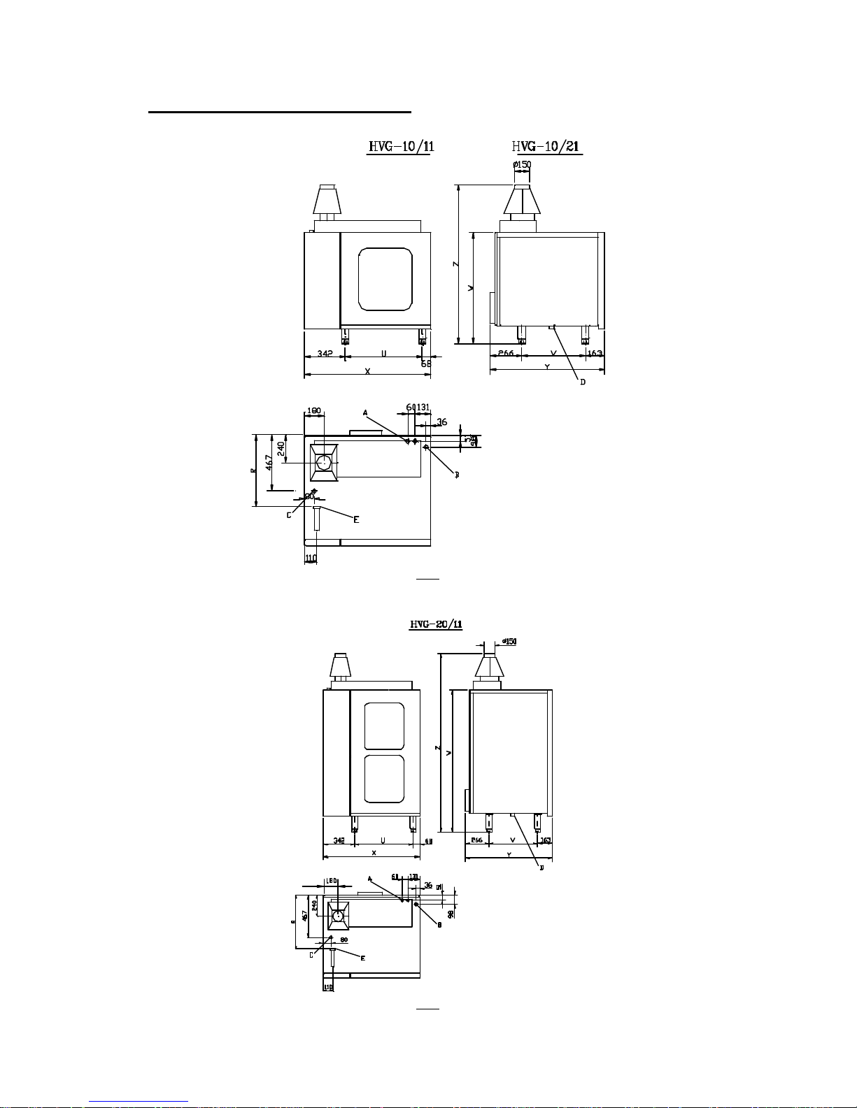
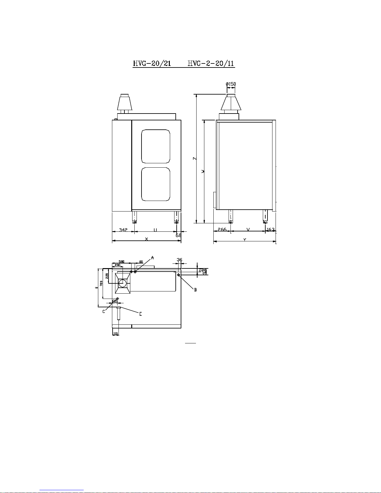
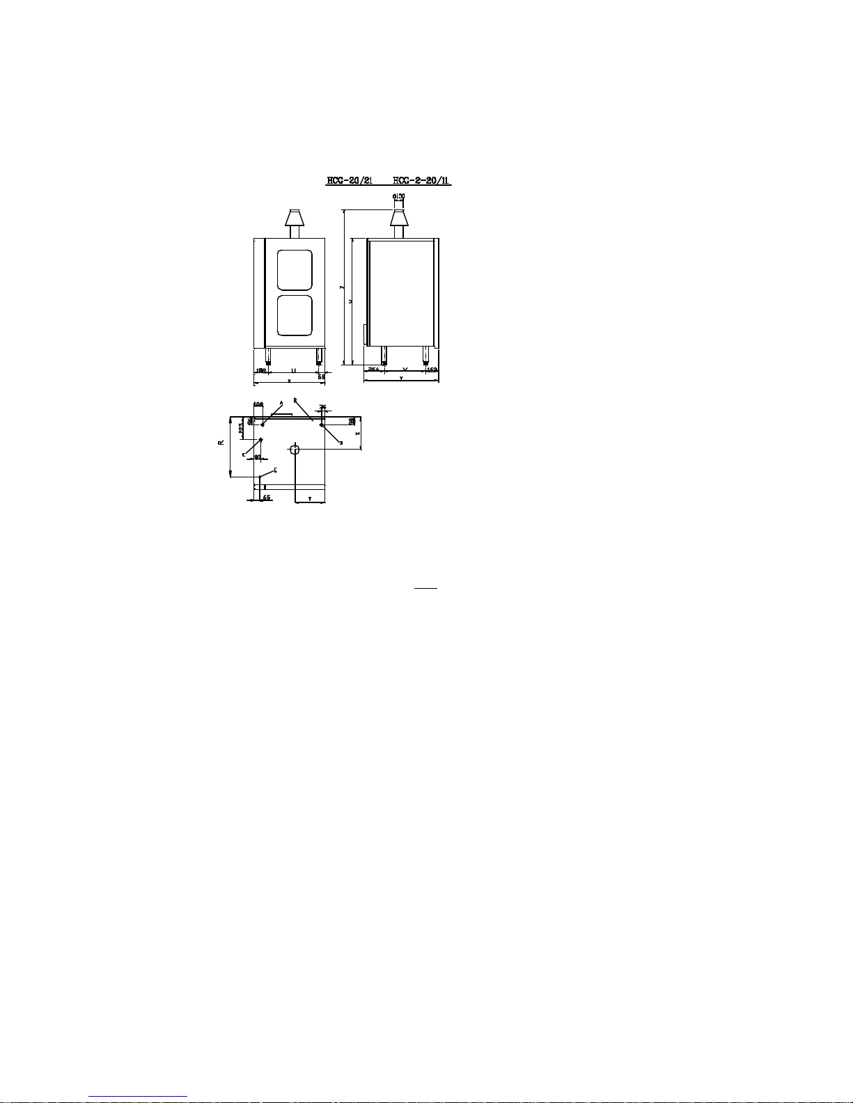
1 MODELS AND DIMENSIONS
fig 1
fig 2
Page 4
4
fig 3
Page 5

5
fig 4
fig 5
Page 6
6
fig 6
A.- Soft water inlet RG ¾”.
B.- General dra in RG 1”.
C.- Electrical supply inlet connector.
D.- Drain cleaning plug.
E.- Gas inlet RG ¾”.
Page 7
7
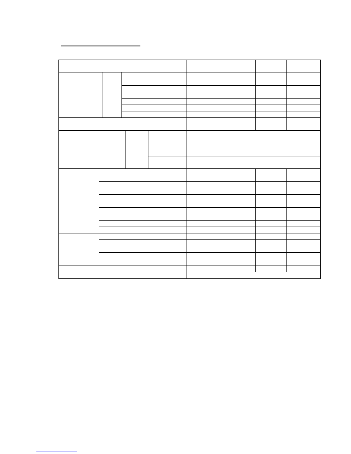
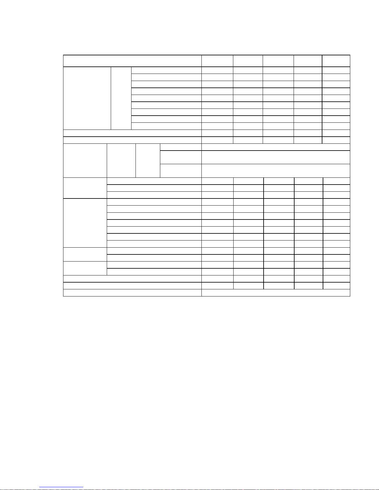
2 CHARACTERISTICS
MODEL HVG-10/11
HVG-10/21
HVG-2-10/11
HVG-20/11
HVG-20/21
HVG-2-20/11
Width X 1060 1180 1060 1180
Depth Y 965 1170 965 1270
Height without chimney W 925 925 1635 1635
Height with chimney Z 1290 1290 2000 2000
Width U 650 770 650 770
Depth V 535 740 535 740
EXTERNAL
DIMENSIONS
mm
Depth Gas R 600 800 600 900
Net weight (Kg.) 210 275 320 430
Electrical power Kw 0.4Kw 0.4Kw 0.6Kw 0.6Kw
Hose
section
2x1,5+T
Fuse Int.
General
10ª
Supply
voltage
220-240V
1N
50-60Hz
Differential
Device
30Ma
Kcal/h (Hs) 34,400 39,560 44,720 72,240
BTU (Hs) 136,500 157,000 177,500 286,700
Gas power
Kw. (Hi) 40,000 46,000 52,000 84,000
Kg/h (29mb)Butane (G -30) 3,330 3,830 4,330 6,990
Kg./h (37 mb) Propane (G-31) 3,280 3,770 4,265 6,890
m³./h (20 mb) Natural gas (G-20) 4,235 4,870 5,500 8,890
m³./h (25 mb) Natural gas (G-25) 4,555 5,170 5,665 9,840
m³./h (8 mb) City gas (G-110) 000 000 000 000
m³./h (8 mb) City gas (G-130) 000 000 000 000
Nominal
consumption
m³./h (8 mb) City gas (G-150) 000 000 000 000
Hot air 90 90 90 90
Performance %
Steam (%) 85 85 85 85
GN 1-1 10 20 20 40
Max. no. trays
GN 2-1 - 10 - 20
Maximum load weight in kg 50 100 100 200
Approximate water consumption (litres/hour) 30 30 30 50
Water inlet pressure Kg/cm 0.5---8
Page 8
8
MODEL
HCG-6/11 HCG-10/11
HCG-10/21
HCG-2-10/11
HCG-20/11
HCG-20/21
HCG-2-20/11
Width X 900 900 1020 900 1020
Depth Y 965 965 1170 965 1170
Height without chimney W 695 925 925 1635 1635
Height with chimney Z 1060 1290 1290 2000 2000
Width U 650 650 770 650 770
Depth V 535 535 740 535 740
Depth Gas R 720 720 920 720 920
Depth chimney S 380 380 450 380 450
EXTERNAL
DIMENSIONS
mm
Width chimney T 370 370 430 370 430
Net weight (Kg.) 135 165 225 275 380
Electrical power Kw 0.40Kw 0.40Kw 0.40Kw 0.60Kw 0.60Kw
Hose Section 2x1.5+T
Fuse Int.
General
10A
Supply voltage
220-240V
1N
50-60Hz
Differential
Device
30mA
Kcal/h (Hs) 12,000 16,340 21,500 26,660 36,120
BTU (Hs) 47,800 64,850 85,300 105,800 143,300
Gas Power
Kw. (Hi) 14,000 19,000 25,000 31,000 42,000
Kg/h (29mb)Butane (G -30) 1,165 1,580 2,080 2,580 3,495
Kg./h (37 mb) Propane (G-31) 1,150 1,560 2,050 2,540 3,445
m³./h (20 mb) Natural Gas (G-20) 1,480 2,010 2,645 3,280 4,435
m³./h (25 mb) Natural Gas (G-25) 1,355 1,970 2,050 2,540 4,310
m³./h (8 mb) City Gas (G-110) 000 000 000 000 000
m. ³/h (8 mb) City Gas (G-130) 000 000 000 000 000
Nominal
consumption
m. ³/h (8 mb) City Gas (G-150) 000 000 000 000 000
Hot air 90 90 90 90 90
Performance %
Steam (%) - - - - -
GN 1-1 6 10 20 20 40
Max. no. trays
GN 2-1 - - 10 - 20
Maximum load weight in kg 30 50 100 100 200
Approximate water consumption (litres/hour) 15 15 30 30 35
Water inlet pressure Kg/cm 0.5---8
Page 9
9
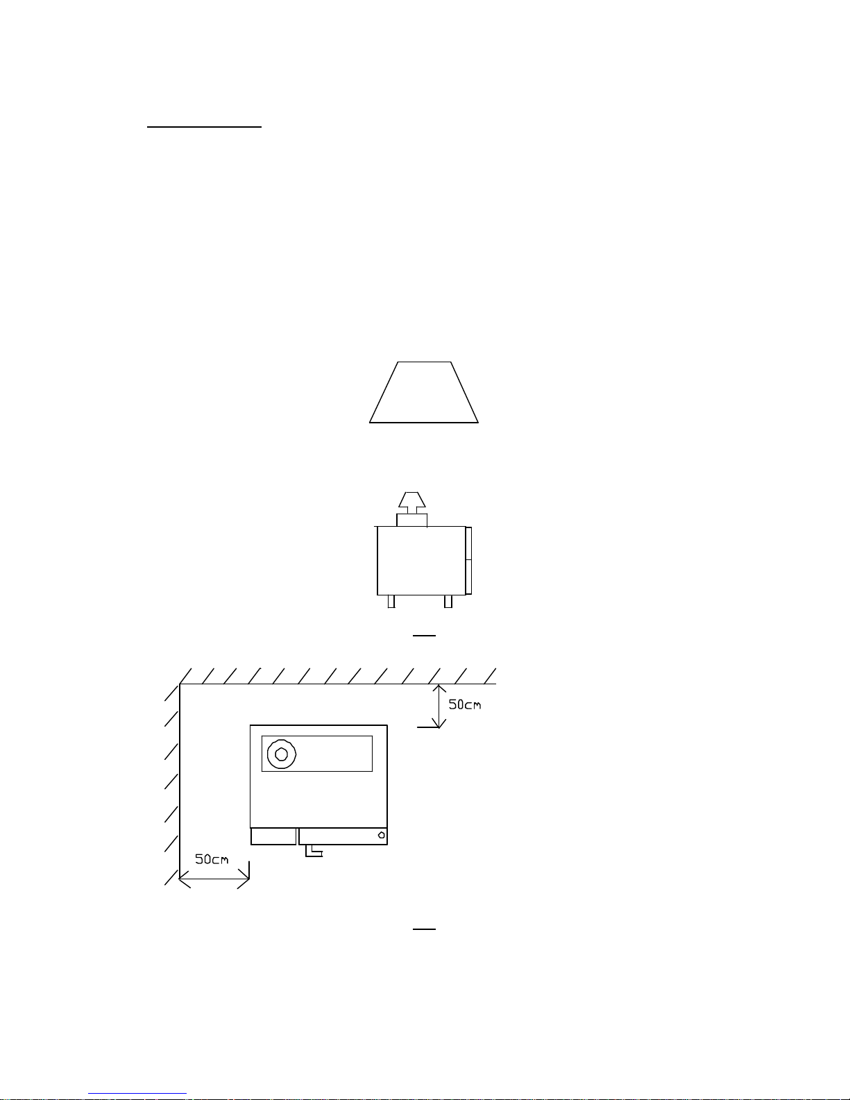
3 LOCATION
It is recommendable to install the extractor hood to expel fumes to the exterior
(see fig 7)
On the left -hand side, there must be a minimum space of 50 cm between the oven and
the next appliance HVG. (see fig 8)
Likewise, the over must not be affected by the steam or heat from other appliances. The
rear panel must be in place at all times.
fig 7
fig 8
Page 10

10
4 INSTALLATION
Before proceeding to install the equipment, make sure that the type of gas set for the
oven coincides with the gas supplied in the distribution network.
4.1 Electrical Connect ion.
− The mains voltage must be the one indicated on the characteristics plate.
− REMOVE THE LEFT-HAND SIDE PANEL in HVG models.
− EXTRACT CONTROL PANEL in HCG models
− Use a polychloroprene cable or another with the same characteristics (HO5RN -F).
− Place a general switch independent of the appliance in the mains outlet with a
distance between contacts equal to or greater than 3 mm.
− A differential grounding shunt device must be installed.
− The appliance must be connected to ground.
− Access the electrical connections strip and fix the cable to the stuffing box, C (see ).
− When installing a number of appliances in a line, these must be connected together to
ground.
4.2 Water inlet.
− Only connect drinking water to the appliance.
− Make the connection to the water mains at point A (see . ), using the hose supplied.
− The water inlet pressure must be between 0.5 and 8 Kg/cm².
− Install a filter and stop cock at the water inlet.
− For water with a hardness of over 10ºF, a water softening unit is required..
− Conductivity of the water 50-2000µS, lower conductivity optional.
Minimum concentration of chlorides Cl under 150 mg./litres.
N the case of values of over 2000µS or when exceeding the limit value for chloride,
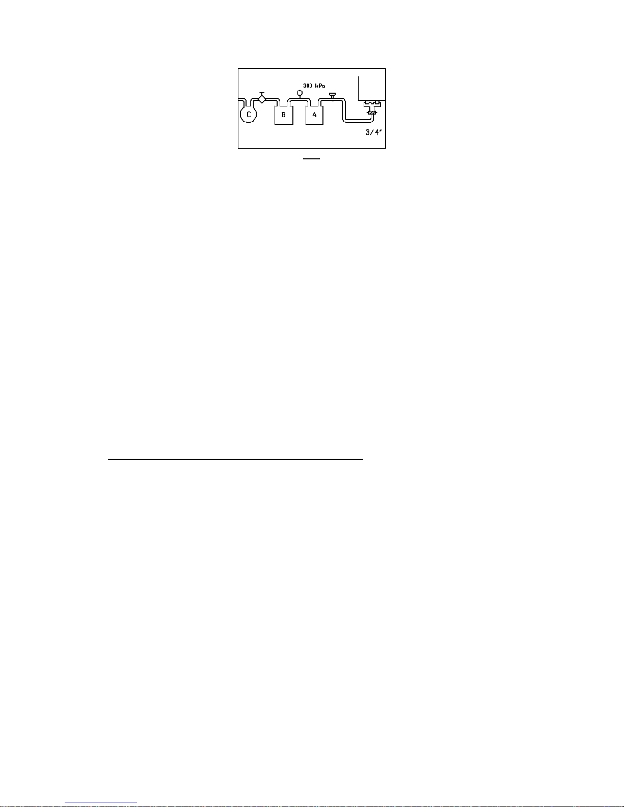
place a hydrogen ion exchanger (see fig 9)
− Redox potential 300 mV, (alternatively chlorine content (CL2) lower than 0,1
mg/litre).
In the case of values of over 300 mV Redox potential, place an activated carbon filter
(observe the filter maintenance intervals)
Sedimentation filter Un (0,08 mm) when the impurities in drinking water are high.
Page 11
11
fig 9
4.3 Drain.
The connector hose must be steam resistant (100ºC).
4.4 Gas inlet.
The connection will be made with a hose fitted with a ½” and ¾” connection in HVG
models.
A stop cock and pressure regulator must be installed between the appliance and the gas
mains.
4.5 Exhaust fume outlet .
The oven must be installed under an extractor hood.(see fig 7)
4.6 Adaptation to different gases.
Gas ovens cannot be adapted to different gases.
Page 12

12
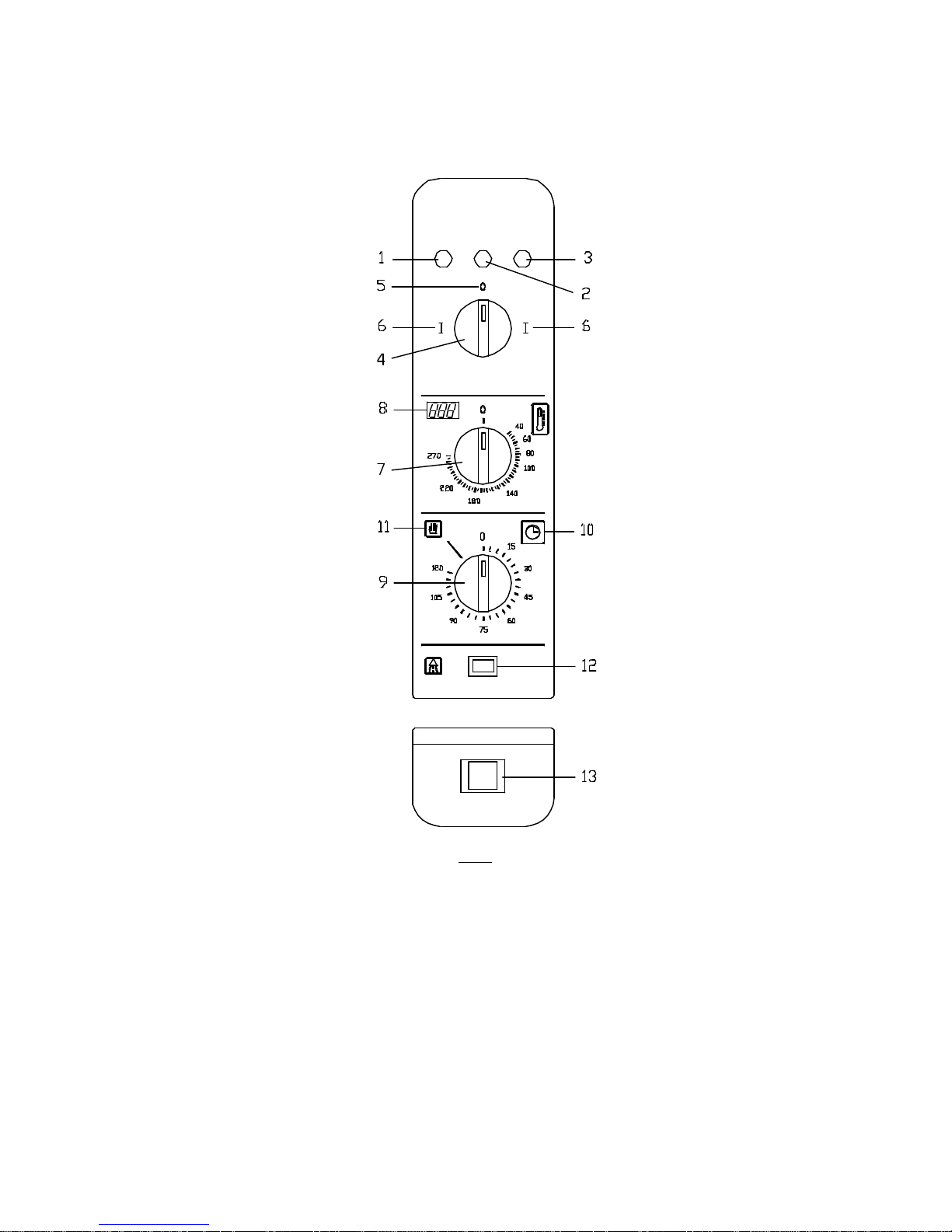
5 CONTROL PANEL
HVG-10/11
HVG-10/21
HVG-2.10/11
HVG-20/11
HVG-20/21
fig 10
1.- Chamber heating indicator. 15.- Indefinite time fixed position (MANUAL).
2.- Oven ON indicator . 16.- Real temperature at probe core.
3.- Steam generator heating indicator. 17.- Core temperature selector.
4.- Mode selector. 18.- Button to increase probe core
5.- Oven OFF position . selection.
6.- Steam mode position 19.- Button to reduce probe core
7.- Low temperature steam mode position. selection.
8.- Regeneration mode position. 20.- Probe core function selector.
9.- Mixed mode position. 21.- Chamber burner ignition reset
10.- Hot air mode position. button.
11.- Temperature selector . 22.- Generator burner ignition reset
12.- Chamber temperature indicator. button.
13.- Time selector. 23.- Lime indicator.
14.- Variable time position 0-120º. 24.- Machine out of service indicator.
(AUTOMATIC)
Page 13
13
HCG- 6/11
HCG-10/11
HCG-10/21
HCG-2.10/11
HCG-20/11
HCG-20/21
fig 11
1.- Chamber heating indicator.
2.- Oven ON indicator.
3.- Chamber water inlet indicator.
4.- General switch.
5.- OFF position (OFF).
6.- ON position (ON).
7.- Temperature selector.
8.- Real chamber temperature.
9.- Time selector.
10.- Variable time position 0-120’ (AUTOMATIC).
11.- Indefinite time fixed position (MANUAL).
12.- Humidifier button.
13.- Ignitio n system reset button.
Page 14

14
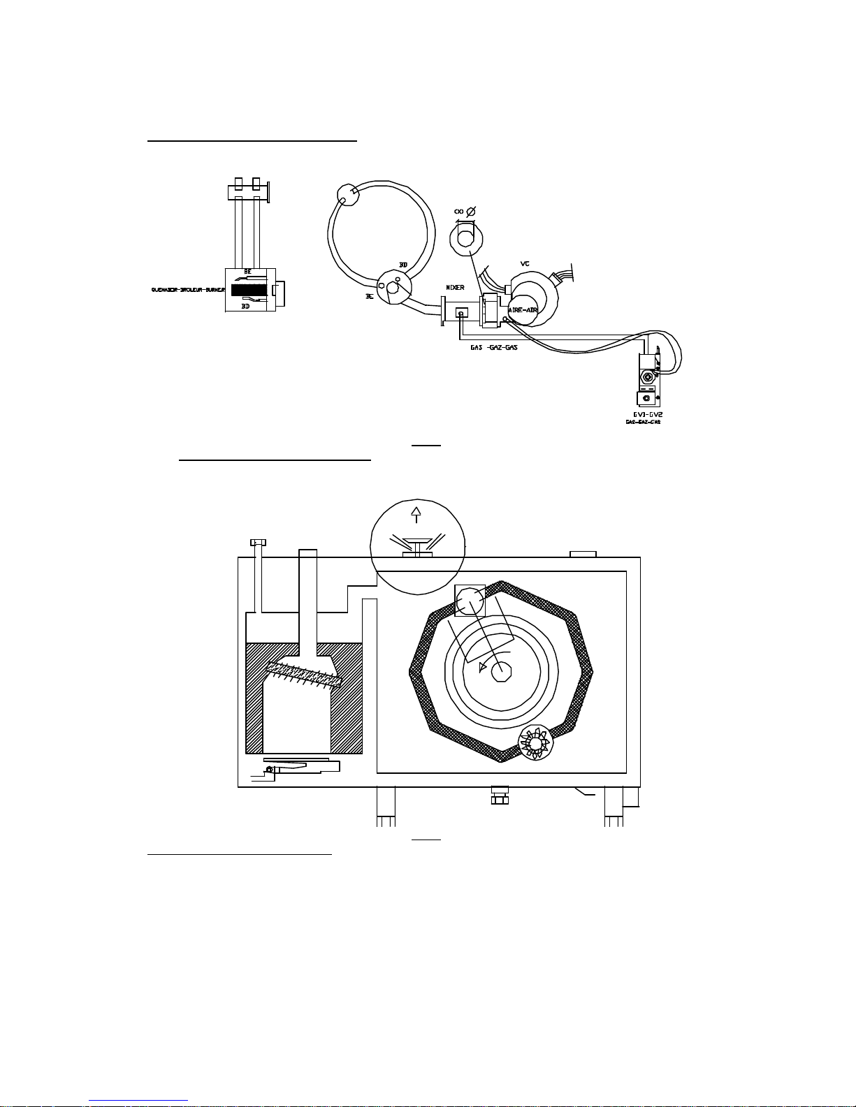
6 FUNCTIONAL DIAGRAM (HVG)
fig 12
1- Steam gas valve
2- Convection gas valve
3- Gas duct from steam generator.
4 –Chamber gas duct.
5- Gas duct to main cover.
6 -Mixer.
7 -Mixer coupling
8 –Blower fan.
9 –Main cover.
10- Chamber burner.
11 –Generator burner.
12 –Chamber heat exchanger.
13-Complete fume manifold.
14 –Complete steam manifold.
15 –Complete chimney.
Page 15

15
Description of the most important components in the
Convection Ignition System (Forced air burner):
VC: Premix centrifugal fan (air blower or supplier) . (fig 28)
This is an air supplier motor for combustion.
-VF: Frequency inverter. (fig -25)
This is the electronics that changes and controls the speed of the fan motor or blower by means of a
voltage variation. We use this to define the two speeds at which the blower fan must work. Ignition speed
S1 and maximum power speed S2.(fig 26)
-GV1-GV2:Convection gas valve.
This is a Honeywell modulating gas solenoid valve. (fig 24) This modulates the gas opening in
accordance with the speed of the blower fan. Valve connected by means of a rubber tube to the blower
fan by means of which it is possible to modulate the gas opening in accordance with the air pressure. (fig
23)
Valves are adjusted for each size of oven or type of gas in the factory only.
CEC: Convection ignition control
This is the electronics that carries out the ignition sequence (spark train- gas valve opening - flame
detection) (fig 15-16 )
Air washer: Washer that defines the amount of correct air for the furnace. (fig 29 )
Mixer: This is the air -gas mixer for combustion. (fig 28 )
BE: This is the spark plug that generates the spark for ignition.(fig 22)
BD: This is the ionisation flame detector. (fig 22)
TC: Chamber thermostat 30 -270ºC
This is the electronic thermostat that controls the chamber temperature (fig. 56). This also has a contact
fixed at 100ºC called T100.
Description of very important components in the
Steam Ignition System (Atmospheric burner):
GV3-GV4: Steam gas valve.
Steam gas solenoid valve SIT 830.(fig 23)
CEV: Steam ignition control
This is the electronics that carries out the ignition sequence (spark - gas valve opening- flame detection)
(fig 15 -16)
Page 16

16
CN: Water level control.
Electronics that control the generator water level. (fig 37 )
BE: This is the spark plug that generates the spark for ignition.(fig 31)
BD: This is the ionisation flame detector.
RE1: Energy regulator.(fig 34)
Electro-mechanical component for controlling electrical contacts.
Note: In steam mode, the blower fan (VC) always works at ignition speed.
Page 17

17
Blower fan sequence VC
Correct ignition.
fig 13
Blower fan sequence VC
Incorrect ignition.
fig 14
Ignition control (CEC and CEV)
fig 15 fig 16
CONNECTION IGNITION SEQUENCE
ACRONYMS PR LR GV SI DII LII
FUNCTIONS RESET
BUTTON
RESET
LIGHT
GAS
VALVE
SPARK
PLUG
FLAME
DETECTOR
HEATING
INDICATION
LAMP
Page 18
18
FUNCTIONAL DIAGRAM HVG and HCG (CONVECTION MODE)
fig 17
HVG CONVECTION MODE (30-270ºC)
fig 18
CONVECTION MODE 30º-270ºC
Convection burner is working.
Chimney open.
Page 19

19
FUNCTIONAL DIAGRAM HVG (STEAM MODE 100º C-ADJUSTABLE STEAM MODE
30-100º C)
fig 19
HVG STEAM MODES 100ºC- AD JUSTABLE STEAM 30-100ºC
fig 20
STEAM MODES 100ºC-ADJUSTABLE STEAM
Convection burner is working.
Chimney closed.
Page 20

20
HVG MIXED-REFRIGERATION MODES 30º-270ºC
fig 21
REGENERATION MODE :
- Initial phase: Both burners simultaneously – chimney open.
-Temperature maintenance: Burners cycle alternatively. 1st Convection –chimney open and 2nd
Steam- chimney closed. (Steam cycles in turn with the RE1 energy regulator 15 sec. ON and 15sec.
OFF)
MIXED MODE :
-Initial phase: Convection burner – chimney open.
-Temperature maintenance: Burners cycle . 1st Convection –chimney open and 2nd Steam - chimney
closed. (Steam cycles in turn with the RE1 energy regulator 15 sec. ON and 15sec. OFF)
Page 21

21
7 FIGURES
fig 22
DETAILED VIEW OF BURNER, IGNITION SPARK PLUG AND FLAME DETECTOR
fig 23
Convection Gas Valve
Adjusted according to:
-Oven size
-Type of gas
Convection ignition
spark plug
Convection flame
detector spark plug
Convection
burner
Gas Valve SIT 830
Steam
GV3-GV4.
Page 22

22
VR 4605-VA 1041B Valve (Convection Gas Valve)
fig 24
Frequency inverter (T-083002)
fig 25
fig 26
P.outlet
P.inlet
Ignition speed
switches
Max
imum operating
speed switches
Detailed view of frequency
inverter switches
Air/gas regulation in ignition.
(maximum speed)
Air/gas regulation in ignition.
(Offset )
((+) clockwise)
Page 23

23
DETAILED VIEW OF GAS AIR MIXTURE IN THE CONVECTION IGNITION SYSTEM AT REAR
OF OVEN
fig 27
DETAILED VIEW OF BLOWER, MIXER AND BURNER SUPPORT
fig 28
DETAILED VIEW OF WASHER
fig 29
VC= EBM fa n
50/60Hz
MIXER
BURNER
AIR WASHER
Diameter 5mm
Page 24

24
Steam burner
Detailed view of steam burner
Detail of chimney seal mechanism
Detailed view of chimney seal
RE1 Energy regulator
TV Steam thermostat
TCN Condensation thermostat
CN Level control
fig 30
fig 31
fig 32
fig 33
fig 34
fig 35
fig 36
fig 37
Page 25

25
HVG (SIDE VIEW OF ELECTRICAL COMPONENTS)
fig 38
Gas intake ¾”
Electrical wiring
connection inlet
Page 26

26
HVG (REAR VIEW)
fig 39
Soft water connection ¾”
Page 27

27
8 ELECTRICAL DIAGRAMS AND ASSEMBLY DIAGRAMS
Acronyms
VF: Frequency inverter
VF2: CONTACT INDICATING THAT THE VC BLOWER FAN IS IN OPERATION.
VF1: CONTACT THAT CLOSES WHEN:
-TC = ON
-BLOWER SPEED = Slow blower ignition speed.
CEC: Convection ignition control .
CEV: Steam ignition control .
RE1: Energy regulator15sec=ON / 15sec =OFF
Page 28

28
Page 29

29
fig 40
Page 30

30
fig 41
Page 31

31
fig 42
Page 32

32
fig 43
Page 33

33
9 PREVENTIVE MAINTENANCE
In order to guarantee the safe, cost-effective and non contaminating operation of your oven, periodic
maintenance is essential. This allows you to keep it in good condition and prolongs its service life. Maintenance
must be done by AUTHORISED TECHNICAL PERSONNEL, at least once a year. Servicing is of vital
importance as the wear or damage of parts are gradual processes and so if a malfunction can be detected in
time, the costs involved are low and the benefits with regard to safety and cost-effectiveness can be very high.
The one-year interval between servicing has been calculated based on an average use of 4 hours per day. If the
unit is used intensively, for example in a catering company, serving must be done at shorter intervals.
1. CONVECTION SYSTEM
1.1 Ignition spark plug
Release and extract the combustion chamber.
Check its status and connections visually.
Clean the detector with “Scotch”
Set the oven to convection mode to activate the spark plug.
Check for correct ignition
1.2 Flame detector
Release and extract the comb ustion chamber.
Check its status and connections visually.
Clean the electrode with “Scotch”
1.3 Mains gas pressure
Check at appliance inlet.
Measure when the appliance is in operation.
(Measurements may be made at the gas valve inlet)
1.4 Gas circuit water-tightness
Check.
1.5 Heat exchanger
Check visually that it is in good condition.
Check the status of the graphite seals.
Replace if damaged.
Page 34

34
2. STEAM SYSTEM
2.1 Lime scale indicator lamps.
If any of these light up,
remove scale in oven as
follows:
1 Turn off the appliance.
2 Turn the water drainage lever "B". When empty, return the lever to the
original position.
3 Extract plug A and pour in deliming liquid (14 litres) .
4 After 6 hours have elapsed, empty the steam generator by turning lever B.
5 Flush the deliming liquid inlet with water. Fit plug A.
6 Close lever B and put oven into operation in the steam mode at low temperature with the thermostat selector
at 0 for 10 minutes.
7 Flush the cooking chamber using the shower fitting. Put the oven into operation in steam mode for 10
minutes.
8 Drain the steam generator on a daily basis.
fig 45
2.2 Burner
Check that the burner turns on and operates correctly.
If there is no ignition spark, change the spark plug, check the cable and connections.
If the problem persists, change the electronic ignition box.
2.3 Boiler
Check that there are no drips.
If there are, change the boiler. In this case, also change the graphite seal that joins the boiler to the chamber.
2.4 Steam condensation thermostat
Make sure that this is working.
2.5 Boiler drainage
Check that the valve and drain are working correctly.
2.6 Water level
Check that this is working correctly and that water does not overflow.
fig 44
Page 35

35
3 OVEN DOOR
3.5 Seal
If this is cracked or da maged, replace.
3.6 Steam leaks
If there are any steam leaks, adjust the hinge and hooks
3.7 Door alignment
Adjust if necessary.
3.8 Handle
If this is loose, tighten or replace.
3.9 Drain
Check and clean if necessary.
3.10 Light
Replace lamp if necessary.
4 CHIMNEY
4.5 Seal
Clean surfaces and grease pins.
If there are any steam leaks, adjust the mechanism.
Change O-ring Q307067
5 CONTROL PANEL
5.5 Core probe
Check that this is working correctly. (To do this, start the oven in steam mode with the probe inside and wait
until it reaches 98ºC)
Replace if damaged or adjust if loose.
5.6 Timer
Check status.
5.7 Electronic thermostat (convection)
Check visually and functionally in convection mode at 270ºC. Replace if this is not working correctly.
6 MISCELLANEOUS
6.5 Cooling fans
Check that these work.
6.6 Miscellaneous
Make a visual check of the entire oven.
Page 36

36
10 TROUBLE SHOOTING
EFFECT CAUSE ACTION
1.-Oven does not operate in any mode.
Green lamp L1 does not come on.
Electronic thermostat display on.
1.1.Door switch IP
1.2.Motor thermal switch FM
1.1.Check – change or adjust
1.2.Check motor thermal switch wires (grey motor
connection cables) or change motor.
2.-Convection burner does not turn on
Green lamp L1 on.
Electronic thermostat display on.
Turbine motor working.
Convection lamp L2 does not come on.
Convection reset button L3 off.
2.1.Chamber thermostat TC
2.2.Safety thermostat TSC
2.1.Check contact TC
2.2. Check contact TSC
3.-Convection burner does not ignite.
Green lamp L1 on.
Electronic thermostat display on.
Turbine motor working.
Convection lamp L2 does not come on.
Check no. of pluses of LED D21 of frequency inverter
(three impulse sequence).
3.1. Faulty inverter VF or blower VC. 3.1 Change.
4 –Convection burner does not ignite.
Green lamp L1 on.
Convection lamp L2 comes on a moment and then turns
off.
Convection reset button L3 on.
Check no. of pluses of LED D21 of frequency inverter
(three impulse sequence).
3.1.Connect blower air/convection gas valve closed.
3.2.Blower connector rubber tube/convection gas valve
broken.
3.3.False contact in ignition control. CEC
3.4 Faulty ignition control. CEC
3.5.Little or no gas
3.6.Flame detection failure
3.7.Gas flow ignited in low convection valve.
3.8.Convection gas valve.
3.9.Spark train failure.
3.1.Check and drill if it is a spare.
3.2.Check whether this is broken or blocked and replace
3.3.Check detection wiring
3.4.Change
3.5.Check with pressure gauge in gas valve
3.6.Check detector-burner position (5-6 mm) and
connections or change detector.
3.7.Check dynamic pressure and increase.
3.8.Change gas valve.
3.9. Check position of burner spark plug (3-4 mm) and
connections
5.-Noise during ignition 5.1.Excessive gas during ignition
5.2.Burner does not correspond to model
5.3.Type of gas does not correspond to model
5.4.Wrong frequency inverter switches.
5.5.Gas valve does not correspond to type of gas.
5.1.Check valve code corresponding to gas and model
5.2.Check pressures in gas valve in burner
5.3.Check pressures and model
5.4.Check and correct (Increase ignition speed).
5.5 Check and correct
6.- Ignition occurs suddenly with a slight explosion 6.1. Wrong frequency inverter switches
6.2 Type of gas does not correspond to model
6.3. Gas valve does not correspond to type of gas
6.1. Check and correct ignition speed.
6.2.Check pressures and model
6.3. Check and correct
Page 37

37
7.- Oven operates for a time and then stops and starts
again.
7.1.Motor thermal switch FM 7.1.Check that the three phases are connected correctly
to motor.
7.1.Check whether there is dampness on external
surfaces of motor
7.1.Check that the turbine turns in the correct direction
7.1.Change motor
8.-Does not generate any steam.
Steam lamp L4 off
8.1.There is no water in mains or water valve V1 is
faulty.
8.2.Steam generator drainage valve open.
8.3.Level electrodes coated with lime.
8.4.Faulty water level control CN
8.1. Check and correct
8.2.Correct
8.3.Clean
8.4. Check and correct
9.-Does not generate steam (but tries to ignite)
Green lamp L1 on.
Water level control not connected to power supply.
9.1.Frequency inverter failure VF
9.2.Faulty blower
9.1. Check and correct
9.2. Check and correct
10.-Does not generate enough steam
Steam gas valve GV5-GV4 active
10.1Chimney open
10.2.Chamber probe broken
10.3.Thermostat T100 loose
10.1. Check and correct
10.2.Change probe
10.3.Adjust thermostat or change thermostat
11.-Does not generate any steam
Lamp L4 off
Lamp L6 on
Lamp L7 on
11.1.Lime deposits on steam generator 11.1.Clean generator and reset thermostat TSV
12.-Generates steam
Lamp L7 on
12.1. Lime deposits on steam generator 12.1. Clean generator and reset thermostat TDC.
NOTE: If lamps L3 are on (locked in convection mode ) or L5 (locked in steam mode ignition) CORRECT AND RESET.
Page 38

38
Frequency inverter failure modes T- 083002:
1. Single pulse of light in red LED D21(fig 47).
Effect: Oven does not ignite. Reset button off.
Possible causes:
- 1.1 Signal cable between frequency inverter and fan (T -083000) is broken.
- (Check connector wires J2 of frequency inverter) connection 1-3
- 1.2 Broken fa n card.
- 1.3 Broken frequency inverter
2. Two pulses of light in red LED D21. (fig 47)
Effect: Oven does not ignite. No flame detection. Reset button on.
Possible causes:
2.1 There is not gas supply.
- 2.2 Flame detector wires broken or with loose contacts.
- 2.3 Faulty INECO combustion control box.
2.4 Faulty spark plug wire or loose contact.
2.5 Spark plug not at correct distance to burner (3-4mm)
2.6 Faulty convection gas valve.
2.7 Air leak in rubber tube from blower to gas valve.
3. Three pulses of light in red LED D21 (fig 47)
Effect: Oven does not ignite. Reset button off.
Possible causes:
- 3.1 Speed detector cable between frequency inverter and fan is broken.
- (Check cables on connector J2 of frequency inverter) Connection 2-4
- 3.2 Faulty fan card.
- 3.3 Faulty frequency inverter.
- 3.4 Blower does not operate.
4. Four pulses of light on red LED D21. (fig 47)
Effect: Over operates. The oven reached temperature slowly because the blower does not reach the
maximum speed.
Possible causes:
Page 39

39
- 4.1 Blower does not work properly.
- 4.2 Frequency inverter does not work properly.
5. Five pulses of light on red LED. D21 (fig 47)
Effect: The oven operates, but ignition is abrupt. The blower does not reach the minimum ignition
speed.
Possible causes:
- 5.1 Blower does not wo rk properly.
5.2 Frequency inverter does not work properly.
6. Continuous light in red LED D21. (fig 47)
Effect: The oven does not ignite.
Possible causes:
- 6.1 Faulty ignition control, or broken internal ignition control fuse.
7. All LEDs off. D21 (fig 47)
Possible causes:
7.1 Check fuse.
7.2 Faulty inverter.
fig 46
Red LED
D21
Connector J2
Page 40

40
Failure modes on display of electronic chamber thermostat:
If the following message appears on the electronic thermostat display:
_ _ 0 Thermocouple or chamber probe cut off.
-Check connection between thermocouple and electronic thermostat
-Change chamber probe
_ _ 1 NTC open.
-Change electronic thermostat.
_ _ 2 Selector potentiometer 30-270ºC broken.
- Change electronic thermostat.
_ _ 3 Selector potentiometer 100ºC broken.
- Change electronic thermostat.
Failure modes in core probe thermostat display:
If the following message appears on the electronic thermostat display:
“_ _ _” Short-circuited core probe.
“EEE” Core probe cut or not connected.
Page 41

41
11 PARAMETERS AND ADJUSTMENTS
The pressure values in ( mbar) are approximate. These are taken with an input pressure of 29 mbar Butane , 37 mbar Propane and 20 mbar Natural Gas
Burner ON
(V max)
Burner OFF
MODEL V ignition S1 V maximum S2 Ø Air washer Gas valve GV1-GV2 P out (mbar) P out (mbar)
HCG 6/11 B.P. Ve=1400 rpm V=4500 rpm Ø14: T-085013 T-085010
0:0,5
-0,8:-0,4
HCG 6/11 Prop. USA-60 Hz " V=5500 rpm " T-085016
HCG 6/11 B.P. Australia " " " T-085010
HCG 6/11 G.N. Ve=2000 rpm V=5000 rpm " T-085011
HCG 6/11 G.N. USA-60 Hz " V=5500 rpm " T-085017
HCG 6/11 G.N. Australia " " " T-085011
HCG 10/11 B.P. Ve=2000 rpm V=4000 rpm Ø18: T-115082 T-115097
0,3:1,1
-0,8:-0´3
HCG 10/11 Prop. USA-60 Hz " V=5000 rpm " T-115100
HCG 10/11 B.P. Australia " " " T-115097
HCG 10/11 G.N. Ve=2500 rpm V=4500 rpm Ø20: T-115083 T-115098
1,3:3
-0,9:0,1
HCG 10/11 G.N. USA-60 Hz " " " T-115101
HCG 10/11 G.N. Australia " " " T-115098
HCG 10/21 B.P. Ve=2000 rpm V=5500 rpm Ø18: T-115082 T-115097
0,5:1,8
-0,9:-0,3
HCG 10/21 Prop. USA-60 Hz " V=6000 rpm " T-115100
HCG 10/21 B.P. Australia " " " T-115097
HCG 10/21 G.N. Ve=2500 rpm V=6000 rpm Ø20: T-115083 T-115098
2:4
-0,8:0
HCG 10/21 G.N. USA-60 Hz " " " T-115101
HCG 10/21 G.N. Australia " " " T-115098
Page 42

42
Steam generator Burner ON Burner OFF
MODELS V ignition S1 V maximum S2 Ø Air washer Gas valve GV1-GV2 Nozzles. (Qty=12) P out (mbar) P out (mbar)
HVG 10/11 B.P. Ve=2000 rpm V=4000 rpm Ø18: T-115082 T-115097 Z-955899
0,3:1,1
-0,8:-0´3
HVG 10/11 Prop. USA-60 Hz " V=4500 rpm " T-115100 "
HVG 10/11 B.P. Australia " " " T-115097 "
HVG 10/11 G.N. Ve=3000 rpm V=4500 rpm Ø20: T-115083 T-115098 Z-956104
1,3:3
-0,9:0,1
HVG 10/11 G.N. USA-60 Hz " " " T-115101 "
HVG 10/11 G.N. Australia " " " T-115098 Z-956109
HVG 10/21 B.P. Ve=2000 rpm V=5500 rpm Ø18: T-115082 T-115097 Z-955899
0,5:1,8
-0,9:-0,3
HVG 10/21 Prop. USA-60 Hz " V=6000 rpm " T-115100 "
HVG 10/21 B.P. Australia " " " T-115097 "
HVG 10/21 G.N. Ve=3000 rpm V=5500 rpm Ø20: T-115083 T-115098 Z-956104
2:4
-0,8:0
HVG 10/21 G.N. USA-60 Hz " V=6000 rpm " T-115101 "
HVG 10/21 G.N. Australia " " " T-115098 Z-956109
Steam generator Burner ON Burner OFF
MODELS V ignition S1 V maximum S2 Ø Air washer Gas valve GV1-GV2 Nozzles. (Qty.=12) P out (mbar) P out (mbar)
HVG 20/11 B.P. Ve=3000 rpm V=6000 rpm Ø22: T-135035 T-135037 Z-955899
HVG 20/11 Prop. USA-60 Hz " " " T-135040 "
HVG 20/11 B.P. Australia " " " T-135037 "
HVG 20/11 G.N. Ve=3500 rpm V=6000 rpm Ø26,3: T-135036 T-135039 Z-956104
HVG 20/11 G.N. USA-60 Hz " " " T-135041 "
HVG 20/11 G.N. Australia " " " T-135039 Z-956109
HVG 20/21 B.P.
HVG 20/21 Prop. USA-60 Hz
HVG 20/21 B.P. Australia
HVG 20/21 G.N.
HVG 20/21 G.N. USA-60 Hz
HVG 20/21 G.N. Australia
Page 43

43
SPEED SELECTORS S1-S2 OF FREQUENCY INVERTER :
0 0000 800 r.p.m.
8 1000 2500 r.p.m.
1 0001 1000 r.p.m.
9 1001 3000 r.p.m.
2 0010 1200 r.p.m.
10 1010 3500 r.p.m.
3 0011 1400 r.p.m.
11 1011 4000 r.p.m.
4 0100 1600 r.p.m.
12 1100 4500 r.p.m.
5 0101 1800 r.p.m.
13 1101 5000 r.p.m.
6 0110 2000 r.p.m.
14 1110 5500 r.p.m.
7 0111 2200 r.p.m.
15 1111 6000 r.p.m.
fig 47
TCN: Steam condenser adjustment
fig 48
Thermostat stud position 82ºC
(Standard adjustment)
Thermostat stud position
For economising water
Thermostat stud position
In order not to waste water
Page 44

44
Adjusting amount of steam in Mixed and Regeneration Mode.
The oven is adjusted for an optimum amount of steam, but if for any reason
the user wants more, do the following:
1. Locate the energy regulator RE 1. this is regulated approximately to give
15 seconds of steam and 15 seconds without steam. Both in Mixed and
Regeneration.
2.Turn clockwise to increase amount of steam.
Regulating steam in: Regeneration and mixed mode
fig 49
fig 50 fig 51
Adjusting I K-type core probe the rmostat K.(red case)
K-type thermocouple (Nickel-chrome/Nickel- aluminium ) “Cr” probe
type parameter in PSE
-Simultaneously activate core probe selector (1) and SET (2), holding SET
down for approximately 4 seconds until “d1” appears on the display (3). (fig
53)
- With DOWN (5) move parameters until (3) “PSE” appears on display.
(fig 54)
- With “PSE” on display press SET again and hold down.
Position of
RE 2
Energy
Regulator
Pin
To obtain more steam, turn the
pin clockwise
RE1
Page 45

45
- With SET held down, press “UP” to choose “Cr” parameter on display for
K-type thermocouple. (fig 54)
Note: If, instead of “Cr” we select “Fe” this corresponds to the black J-type
core thermostat (Iron – Costanta).
Core probe thermostat
fig 52
fig 53
Electronic chamber thermostat adjustment
1/ ADJUSTMENT OF MAXIMUM STEAM TEMPERATURE (100º C).
Move blue switch 1 to ON . When the thermostat pin is turned the display must show 100. To adjust this
value, turn potentiometer P2 (fig 55).
Once adjusted, set switch 1 to OFF position.
2/ ADJUSTMENT OF MAXIMUM CONVECTION TEMPERATURE ( 30 – 270º C)
Mover blue switch 2 to ON . When the thermostat pin is turned the display must show a maximum
temperature of 270º C. To adjust this value, turn potentiometer P5 (this value is adjustable).
Once adjusted, set switch 2 to OFF position.
3/ ADJUSTMENT OF REAL TEMPERATURE INSIDE THE OVEN AND THE TEMPERATURE OF
THE ELECTRONIC THERMOSTAT DISPLAY.
Insert a calibrated thermostat in the oven and set the furnace to work in STEAM mode.
When it is seen that the oven is working at a stable temperature of 100º C with respect to the thermometer
inside, the temperature cut off at 100º C in steam mode is done with the electronic thermostat. The
adjustment of the temperature cut off at 100ºC and display is done with the potentiometer P3 with respect
to the thermometer inside the oven.
NOTES
The adjustment of the electronic thermostat is carried out in accordance with the temperature
reference indicated by the calibrated thermos tat inserted indise the oven in order to control the real
temperature .
Page 46

46
Electronic Thermostat (R743013)
fig 54
Parameters for distance between Ignition Spark Plug . BD Flame
detector with convection burner
fig 55
Blue switch
P2
P5
P3
The burner seal must not coincide with the BE and
BD position
Convection burner
Page 47

47
12 RECOMMENDED SPARES
LIST OF RECOMMENDED SPARES IN HVG AND HCG CONVECTION OVENS
Z953004 Combustion control
S333001 Energy regulator
R343072 Level detector
R253049 Motor 230 -240V 50/60Hz
T113030 Function selector switch
R743013 Electronic thermostat
T113010 50/60Hz chimney motor
Z100522 Door magnetic switch
Z200506 Door magnet.
T083002 Frequency inverter
T085711 Convection ignition electrode (6/11)
T115711 Convection ignition electrode (10/11, 10/21 )
T115712 Convection detection electrode (6/11 ,10/11, 10/21 )
T135704 Convection ignition electrode (20/11,20/21)
T135705 Convection detection electrode (20/11,20/21)
R725079 Electrode seal.
Q307067 O-ring
T083000 Fan EBM (6/11, 10/11, 10/21, 20/11) 50/60Hz
T143000 Fan EBM (20/21) 50/60Hz
Z952201 Valve SIT 830 50Hz
T085010 Adjusted convection gas valve BP (6/11) 50Hz
T085011 Adjusted convection gas valve GN (6/11) 50Hz
T115097 Adjusted convection gas valve BP (10/11 y 10/21) 50Hz
T115098 Adjusted convection gas valve GN (10/11 y 10/21) 50Hz
T135037 Adjusted convection gas valve BP (20/11) 50Hz
T135039 Adjusted convection gas valve GN (20/11) 50Hz
T155018 Adjusted convection gas valve BP (20/21) 50Hz
Adjusted convection gas valve GN (20/21) 50Hz
T133004 Digital thermostat TIPO K
T113007 Core probe unit TIPO K (10/11 y10/21)
T133000 Core probe unit TIPO K (20/11 y20/21)
T085710 Convection burner (6/11)
T115710 Convection burner (10/11 y 10/21)
T145712 Convection burner (20/11 20/21)
Z955801 Steam burner
Z955802 Steam ignition electrode
Z955803 Steam detection electrode
1100002811 Complete steam generator KIT HVG (10/11, 10/21, 20/11)
T115037 Steam inlet seal
Page 48

48
ANEXO: TRANSFORMACIÓN A DIFERENTES GASES
PROCESO TRANSFORMACIÓN TIPO GAS
IMPORTANTE: Para transformar el tipo de gas del horno se requiere
cambiar y modificar las siguientes piezas:
-1/ Válvula gas convección GV1-GV2.
-2/ Arandela de aire.
-3/ Posicionar los interruptores S1 y S2 del variador de frecuencia VF
según indicaciones tabla de parámetros.
Además: Para modelos vapor HVGs
-4/ Inyectores de gas del generador vapor (solo en modelos HVG).
(VER TABLA CORRESPONDIENTE A PARÁMETROS y REGULACIONES POR
MODELO)
Page 49

49
PIEZAS A CAMBIAR PARA CONVERSION A DIFERENTES GASES
Cambiar arandela aire
(2)
Cambiar válvula
gas convección
(1)GV1-GV2
Cambiar inyectores gas
quemador del
generador vapor (4)
Modificar posición en S1 Y
S2 los interruptores del
variador de frecuencia VF
(3)
Page 50

50
1º Cambiar válvula de gas convección.
2º Cambiar arandela aire según indica detalle.
UBICACION DE LA
ARANDELA DE AIRE
Válvula Gas Convección GV1 GV2
Regulada según:
-Tamaño horno
-Tipo de gas
Válvula Gas Vapor
GV3-GV4.
ARANDELA DE AIRE
Page 51

51
3º Posicionar los in terruptores del variador de frecuencia según modelo corresponda tanto en S1 y
S2 según tablas.
Variador encendido HVG (T-083002)
4º Cambiar inyectores gas quemador del generador de vapor (Solo HVG)
Quemador vapor Detalle quemador vapor
Inyectores vapor
Conmutadores
velocidad
encendido S1
Conmutadores
velocidad
régimen S2
Detalle de los conmutadores
del variador de frecuencia .
Posición ON (arriba)=1
Posición (abajo)=0
Page 52

52
PARAMETROS Y REGULACIONES
Los valores de presión en ( mbar) son orientativos. Estos estan tomados con una presión de entrada de 29 mbar Butano , 37 mbar Propano y 20 mbar Gas Natural
Quemador ON
(V max)
Quemador OFF
MODELO Vencendido S1 Vmáxima S2 Ø Arandela aire Válvula de gas GV1-GV2 P out (mbar) P out (mbar)
HCG 6/11 B.P. Ve=1400 rpm V=4500 rpm Ø14: T-085013 T-085010 0:0,5 -0,8:-0,4
HCG 6/11 Prop. USA-60 Hz " V=5500 rpm " T-085016
HCG 6/11 B.P. Australia " " " T-085010
HCG 6/11 G.N. Ve=2000 rpm V=5000 rpm " T-085011
HCG 6/11 G.N. USA-60 Hz " V=5500 rpm " T-085017
HCG 6/11 G.N. Australia " " " T-085011
HCG 10/11 B.P. Ve=2000 rpm V=4000 rpm Ø18: T-115082 T-115097 0,3:1,1 -0,8:-0´3
HCG 10/11 Prop. USA-60 Hz " V=5000 rpm " T-115100
HCG 10/11 B.P. Australia " " " T-115097
HCG 10/11 G.N. Ve=2500 rpm V=4500 rpm Ø20: T-115083 T-115098 1,3:3 -0,9:0,1
HCG 10/11 G.N. USA-60 Hz " " " T-115101
HCG 10/11 G.N. Australia " " " T-115098
HCG 10/21 B.P. Ve=2000 rpm V=5500 rpm Ø18: T-115082 T-115097 0,5:1,8 -0,9:-0,3
HCG 10/21 Prop. USA-60 Hz " V=6000 rpm " T-115100
HCG 10/21 B.P. Australia " " " T-115097
HCG 10/21 G.N. Ve=2500 rpm V=6000 rpm Ø20: T-115083 T-115098 2:4 -0,8:0
HCG 10/21 G.N. USA-60 Hz " " " T-115101
HCG 10/21 G.N. Australia " " " T-115098
Page 53

53
Generador vapor Quemador ON Quemador OFF
MODELOS Vencendido S1 Vmáxima S2 Ø Arandela de aire Válvula de gas GV1-GV2 Toberas. (cant=12) P out (mbar) P out (mbar)
HVG 10/11 B.P. Ve=2000 rpm V=4000 rpm Ø18: T-115082 T-115097 Z-955899 0,3:1,1 -0,8:-0´3
HVG 10/11 Prop. USA-60 Hz " V=4500 rpm " T-115100 "
HVG 10/11 B.P. Australia " " " T-115097 "
HVG 10/11 G.N. Ve=3000 rpm V=4500 rpm Ø20: T-115083 T-115098 Z-956104 1,3:3 -0,9:0,1
HVG 10/11 G.N. USA-60 Hz " " " T-115101 "
HVG 10/11 G.N. Australia " " " T-115098 Z-956109
HVG 10/21 B.P. Ve=2000 rpm V=5500 rpm Ø18: T-115082 T-115097 Z-955899 0,5:1,8 -0,9:-0,3
HVG 10/21 Prop. USA-60 Hz " V=6000 rpm " T-115100 "
HVG 10/21 B.P. Australia " " " T-115097 "
HVG 10/21 G.N. Ve=3000 rpm V=5500 rpm Ø20: T-115083 T-115098 Z-956104 2:4 -0,8:0
HVG 10/21 G.N. USA-60 Hz " V=6000 rpm " T-115101 "
HVG 10/21 G.N. Australia " " " T-115098 Z-956109
Page 54

54
Generador vapor Quemador ON Quemador OFF
MODELOS Vencendido S1 Vmáxima S2 Ø Arandela de aire Válvula de gas GV1-GV2 Toberas. (cant=12) P out (mbar) P out (mbar)
HVG 20/11 B.P. Ve=3000 rpm V=6000 rpm Ø22: T-135035 T-135037 Z-955899
HVG 20/11 Prop. USA-60 Hz " " " T-135040 "
HVG 20/11 B.P. Australia " " " T-135037 "
HVG 20/11 G.N. Ve=3500 rpm V=6000 rpm Ø26,3: T-135036 T-135039 Z-956104
HVG 20/11 G.N. USA-60 Hz " " " T-135041 "
HVG 20/11 G.N. Australia " " " T-135039 Z-956109
HVG 20/21 B.P.
HVG 20/21 Prop. USA-60 Hz
HVG 20/21 B.P. Australia
HVG 20/21 G.N.
HVG 20/21 G.N. USA-60 Hz
HVG 20/21 G.N. Australia
Page 55

55
SELECTORES DE VELOCIDAD S1-S2 DEL VARIADOR DE FRECUENCIA :
0 0000 800 r.p.m. 8 1000 2500 r.p.m.
1 0001 1000 r.p.m. 9 1001 3000 r.p.m.
2 0010 1200 r.p.m. 10 1010 3500 r.p.m.
3 0011 1400 r.p.m. 11 1011 4000 r.p.m.
4 0100 1600 r.p.m. 12 1100 4500 r.p.m.
5 0101 1800 r.p.m. 13 1101 5000 r.p.m.
6 0110 2000 r.p.m. 14 1110 5500 r.p.m.
7 0111 2200 r.p.m. 15 1111 6000 r.p.m.
fig 56
Page 56

Page 57

57
 Loading...