

Page 1
N51J015F1-00
USER INSTRUCTIONS
AND
TECHNICAL INSTRUCTIONS
FE-24E // FE-27E
TTo Domestic Hot W
o Domestic Hot W
ater:
ater:
FE-24E
Minimum 7.6 kW (25,932.26 Btu/h)
Maximum 23.7 kW (80,867.71 Btu/h)
FE-27E
Minimum 7.8 kW (26,614.69Btu/h)
Maximum 27 kW (92,127.78Btu/h)
T
T
o Central Heating:
o Central Heating:
FE-24E
Minimum 7.6 kW (25,932.26 Btu/h)
Maximum 23.7 kW (80,867.71 Btu/h)
FE-27E
Minimum 7.8 kW (26,614.69 Btu/h)
Maximum 27 kW (92,127.78 Btu/h)
BOILER OUTPUT
BOILER OUTPUT
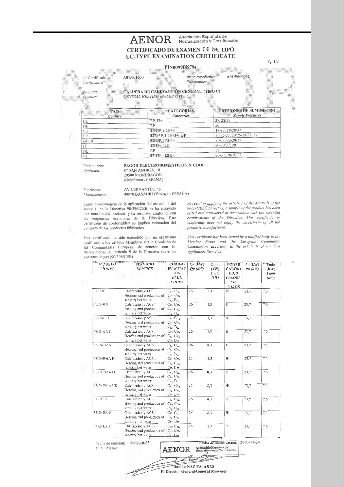
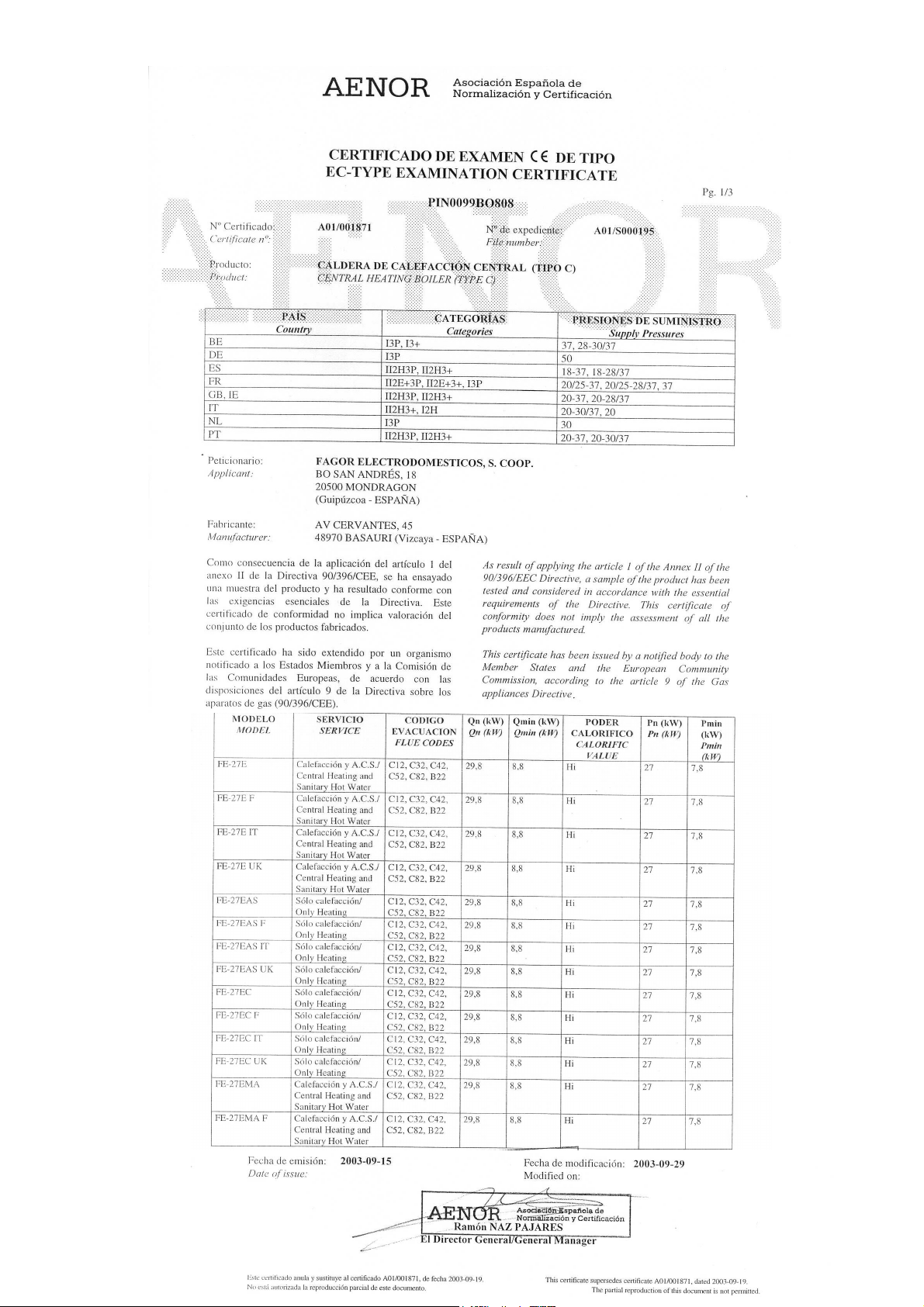
EC-TYPE EXAMINATION CERTIFICATE
PIN0099BN794 (FE-24E)
PIN0099BO808 (FE-27E)
Page 2

2
The compliance with a British Standard does not, of itself, confer immunity from legal obligations. In particular the installation of this appliance must be in accordance with the relevant requirements of the Gas
Safety(Installation and Use) Regulations 1984 as amended, current IEE Wiring Regulations, local Building
Regulations, Building Standards (Scotland)(Consolidation) and byelaws of the local Water Company. Health
and Safety Document No. 635 (Electricity at Work Regulation). It should in accordance with the relevant recommendations of the following British Standards.
BS 6798:1987 Specifications for installation of gas fired hot water boilers of rated input not exceeding 60 kW
BS 5449:1990 Central Heating for Domestic Premises.
BS 5546:1990 Installation for gas hot water supplies for domestic purposes.
BS 5440:1990 Flues and Ventilation for gas appliances of rated input not exceeding 60 kW: Flues.
BS 5440:1990 Flues and Ventilation for gas appliances of rated input not exceeding 60 kW: Air Supply.
BS 6891:1988 Installation of low pressure gas pipework installations up to 28 mm (R1)
To ensure that the installation will perform to the highest standards, the system and components should conform to any other relevant British Standards in addition to those mentioned in the instructions.
The appliance is not suitable for external installation.
Page 3

USER INDEX
Pág.
1.- CONTROL PANEL 4
2.- PREPARING THE BOILER FOR SERVICE 4
3.- USER INSTRUCTIONS 5
4.- MAINTENANCE 5
5.- PRECAUTION AGAINST FREEZING 6
6.- ANTI PUMP SEIZURE DEVICE 6
7.- FAULT CODES 6
INSTALLER INDEX
8.- HOMOLOGATION CERTIFICATE 7
9.- DESCRIPTION OF THE APPLIANCE 8
*Principal components 8
*Operation and safety controls 8
10.-TECHNICAL DATA 9
11.-FUNCTIONAL DIAGRAMS 10
*Gas and water system 10
*Electrical circuit diagrams 10
12.-DIMENSIONS AND CONNECTION DETAILS 11
13.-HYDRAULIC SYSTEM CHARACTERISTICS 11
*Domestic hot water 11
*Central heating 11
14.-INSTALLATION OF THE BOILER 12
15.-Ø 60-100 mm HORIZONTAL CONCENTRIC COMBUSTION PRODUCT EXTRACTION AND
AIR INTAKE 13
16.-Ø 80-125 mm HORIZONTAL CONCENTRIC COMBUSTION PRODUCT EXTRACTION AND
AIR INTAKE 14
17.-Ø 80 mmTWIN-PIPE COMBUSTION PRODUCT EXTRACTION AND AIR INTAKE 15
18.-80-125 mm VERTICAL CONCENTRIC COMBUSTION PRODUCT EXTRACTION AND AIR
INTAKE. 16
19.-ELECTRICAL CONNECTIONS 17
*Connection of a room thermostat (optional) 17
20.-CONTROL PANEL 17
21.-PREPARING THE BOILER FOR SERVICE 18
22.- USER INSTRUCTIONS 18
23.-MAINTENANCE 19
24.-PRECAUTION AGAINST FREEZING 20
25.-ANTI PUMP SEIZURE DEVICE 20
26.-GAS CHANGE 21
27.-FAULT CODES 22
28.-FAULT FINDING 23
Page 4
4
2.- COMMISSIONING THE BOILER
1.- CONTROL PANEL
USER
FE-24E
5
6
7
1
2
3
4
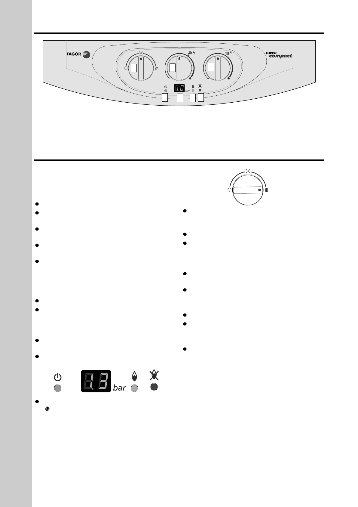
1.- Digital Display
2.- Heating temperature selector
3.- D.H.W temperature selector
4.- Main control switch and reset
5.- Boiler ON indicator light
6.- Burner on indicator light
7.- Reset indicator light
Connect the boiler to a 230V ~50 Hz mains supply.
VERY IMPORTANT: before turning the boiler on
make sure that the installation has been filled.
Domestic hot water
Turn on the cold water stopcock beneath the boiler.
Fill the unit by turning on the various hot water taps
in the installation.
Make sure that the assembly is completely airtight
and watertight.
The installation of a scale reducer/water softener is
recommended in hard water areas
To increase the hot water temperature, reduce the
flow of water at the hot water tap. This may be necessary in winter months.
Central heating system
The correct installation is to be carried out as follows:
Open the radiator air vents.
With the stopcock on and domestic cold water
going through to the boiler, fill the central heating system by opening the filling tap provided by your
installer.
Close the air vents off once water starts coming out
of each of them.
Close the filling tap when the pressure gauge
exceeds the pressure of 1.3 bar. Max = 1.5 bar.
By turning the main control switch to the winter setting . When the pump works the pressure in the digital display increases.
Vent the central heating system once more. Then
let the pressure in the system settle at 1.3 bar. Max =
1.5 bar..
Make sure that there are no leaks in the installation.
Make sure that the heating system is completely
full and vented. The pressure gauge should show
between 1.3 and 1.5 bar with cold water in the heating system.
Make sure that the boiler is wired to the correct volt-
age.
Make sure that the combustion flue outlet is not
restricted.
Gas circuit
Turn on the gas stopcock to the installation.
Check that the whole gas circuit and gas connec-
tions to the boiler are airtight.
Settings
Before leaving the factory the boiler is pre-set in
accordance with the information on the adhesive data
plate, and therefore needs no further adjustment.
Should the type of gas need to be changed, check
with the corresponding section.
Page 5
5
3.- USERS INSTRUCTIONS
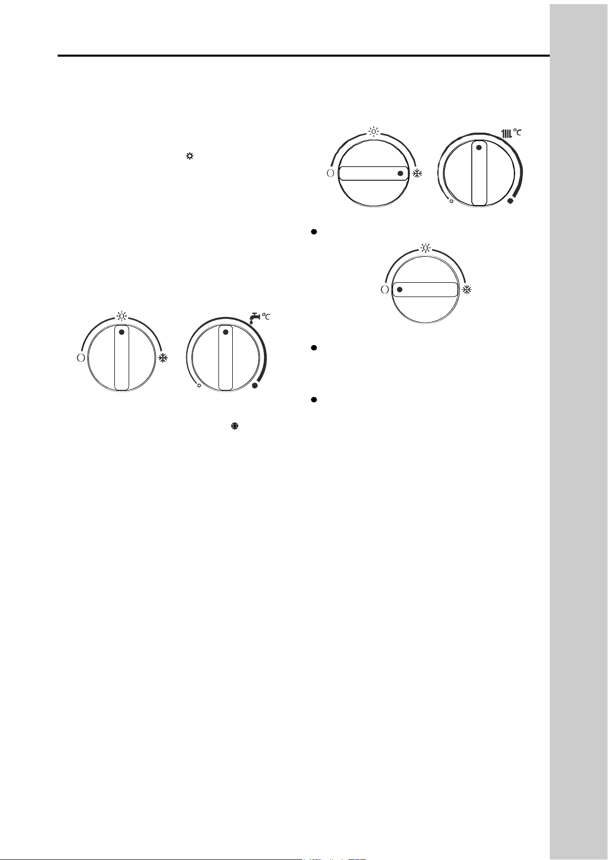
Domestic hot water service.
Turn the main control switch in the summer setting in
order to turn the boiler on , see the figure below
(the green light turns on). At that moment the boiler
will be ready to supply domestic hot water whenever
there is a demand for it.
When you turn on any of the hot taps the boiler will
automatically come on with the pilot light switching on
first of all followed by the burner. A water temperature
of between 35° and 60° C can be selected by turning
the domestic hot water temperature regulating knob.
When the D.H.W. temperature regulating knob is
turned the digital display will show the values of the
temperature.
Hot water and central heating service.
Turn the switch to the winter setting . The burner
will automatically fire up if the clock and/or the roomthermostat are calling for heat. A temperature of
between 60° and 85° C can be selected by turning
the heating temperature regulating knob. This will
stay on until it achieves the temperature selected
either in the room thermostat or in the boiler itself.
Whenever domestic hot water is required when it is at
the central heating setting, the boiler is designed to
give priority to the supply of domestic hot water, with
the central heating on hold, until the demand for
domestic hot water ceases. When the D.H.W. temperature regulating knob is turned the digital display
will show the values of the temperature.
Switching off the boiler.
Turn the main switch to the setting O.
Reset of the boiler.
This unit has a built-in reset indicator. Whenever
any fault is detected in the ignition process, the boiler goes to lock out and the reset indicator switches
on and the fault code is shown in the display.
To reset the boiler turn the main switch to position
O. The reset indicator should then turn off.
When the system pressure either falls down to 0.6
bar or goes over 2.8 bar, the display will shown F-3.
It needs to fill it up to 1.3-1.5 bar (when system cold).
IMPORTANT: If the boiler has not been used for a
length of time, or a new gas bottle is connected, the
unit could lock out due to the presence of air in the
pipes. Should this happen, the ignition procedure
should be repeated until the gas circuit is cleared of
all air in the gas supply.
USER
Check the gas connections and make sure that the gas is coming into the boiler (that the gas tap is open)
Make sure that the heating system is completely full and vented. The pressure gauge should show between
1.3 and 1.5 bar with cold water in the heating system.
Make sure that the electricity supply to the boiler is switched on.
Page 6
6
4.- FROST PROTECTION
5.- ANTI PUM SEIZURE DEVICE
6.- FAULT CODES
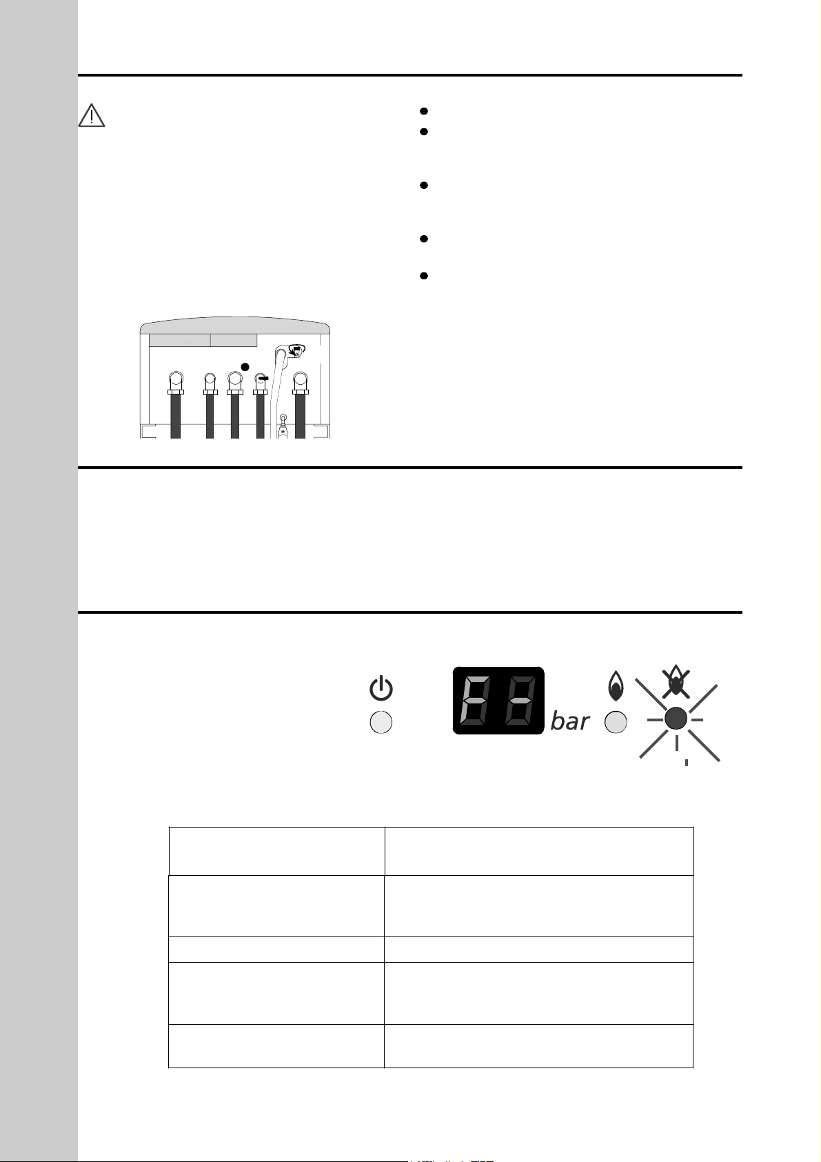
Should a fault develop within the boiler
(diagnostic), the P.C.B. will diagnose the
possible cause via the reset indicator light
(Red Neon) and the digital display. The
fault will be shown in the display.
Each fault code begins with an “F” followed by a number. Ranging from 1 - 13.
To reset the fault use the reset switch (4)
(see Control Panel page 4)
The boiler has an frost protection security system.
IMPORTANT: the boiler must be electrically
supplied and gas connected for this to operate.
Frost protection
When the heating thermistor detects a temperature of
6ºC, only the pump will switch and will continue to run
until a temperature of 9ºC is obtained.
If the temperature drops to 3ºC, the boiler will start on
minimum power until the temperature of 20ºC is
obtained.
NOTE: If the boiler is not to be used for a long period drain the heating installation using the valve (Z)
beneath the boiler and the D.H.W. installation.
The D.H.W circuit must be drained down as follows:
Turn off the cold water supply.
Open all the hot water outlet taps in the installation
(at least one tap should be found at a level lower than
the boiler).
Release the tap to drain the flow switch to allow air
to come in and for the stored water in the boiler to be
able to leave.(see figure)
When the operation is finished, close the hot water
outlet taps and the draining tap.
To put the boiler back into service, open the cold
water inlet tap.
When the boiler is not being used, the pump will automatically run for one minute every 24 hours to prevent seizure. TO ENSURE OPERATION OF THIS
DEVICE ELECTRICAL SUPPLIES MUST BE ON.
If the pump jammed when the appliance is turned
back on, consult your installer or service engineer.
USER
Z
NUMBER OF 1 SEC
‘FLASHES’
FAULT
1
Lack of gas or ignition problems; Flame
supervision failure
Burner on but flame Indicator Off; H L
2
Air Pressure Switch Failure
3
If the central heating pressure drops
below 0.6 bar or gets above 2.8 bar ,
the boiler goes to lock out
4
The overheat thermostat blocks out the
boiler
Page 7
7.- CERTIFICATE
INSTALLER
Page 8
Page 9

9
The FE-24E and the FE-27E are a wall hung, room
sealed, fan assisted, microprocessor controlled fully
modulating gas combination boilers for providing
both central heating and domestic hot water.
1.- Casing
2.- Air pressure switch
3.- Fan
4.- High limit stat
5.- Copper heat exchanger
6.- Expansion vessel
7.- Combustion chamber
8.- Flame sensing electrode
9.- Ignition electrodes
10.- Circulation Pump with Automatic Air Vent
11.- Modulating gas valve
12.- Low water pressure sensor
13.- Plate heat exchanger
14.- Compact hydraulic group including 3 way valve
15.- Printed Circuit Board (PCB)
16.- Control panel
Principal Components
HEAT EXCHANGER copper.
BURNER stainless steel.
MODULATING GAS VALVE with double safety
valves.
PLATE HEAT EXCHANGER stainless steel
(D.H.W.).
THREE-WAY VALVE part of the compact hydraulic
group.
CIRCULATION PUMP with automatic air vent and
speed selector.
EXPANSION VESSEL, on right hand side of the
boiler.
FAN for the extraction of combustion products and
induction of combustion air.
Operation and Safety Controls
THERMISTORS (NTC) There are two thermistors
fitted for automatic control of the domestic hot water
and the central heating flow temperature.
OVERHEAT THERMOSTAT for the boiler's protec-
tion against overheating (closes the gas valve).
PRESSURE RELIEF VALVE opens at 3.5 bar. Must
be terminated externally in a downward direction
ELECTRONIC CONTROL CARD allows amongst
others, the following:
- Temperature selection for central heating from 60
to 85°C.
- Temperature selection for domestic hot water from
35 to 60°C.
- Flame control
- Continuous modulation of the gas valve.
- Ignition control
- Frost protection in the central heating circuit.
- Seizure of the pump.
AIR PRESSURE SWITCH. Prevents the boiler fir-
ing if there is insufficient air supply due to a fault or
blockage.
FLAME SENSING ELECTRODE, controls the
flame in the burner.
LOW WATER PRESSURE SENSOR, prevents the
boiler operating with insufficient circuit pressure and
when the pump is not working.
8.- DESCRIPTION OF THE APPLIANCE
1
2
3
4
5
6
7
8
9
10
11
12
13
14
15
16
Page 10

10
9.- TECHNICAL DATA
Models
FE-24E
FE-27E
Category
II
2H3P
Type
C12,C32,C42,C52,C82,B
22
kW
23.7
27
Maximum output
kcal/h
20,382
23,220
kW
7,6
7.8
Central heating performances
Minimum output
kcal/h
6,536
6,708
kW
23.7
27
Maximum output
kcal/h
20,382
23,220
kW
7.6
7.8
Domestic hot water performances
Minimum output
kcal/h
6,536
6,708
Domestic hot water flow 25ºC increase (l/min)
13.6
15.48
Domestic hot water flow rate (l/min)
10
(34ºC i ncrease)
13
(29,76ºC increase)
Minimum flow rate for activating D.H.W. (l/min)
2
Maximum
Central hea ting
3
Maximum
D.H.W.
10
Operating pressure (bar)
Minimum D.H.W. activation
0,3
Expansion vessel capacity (L)
7
Central heating circuit
60-85
Temperature selection range (ºC)
D.H.W. circuit
35-60
Natural G20
20
Gas inlet pressure (mbar)
Propane G31
37
Natural G20 (m3/h)
2.78
3.19
Gas consumption (Hi)
Propane G31 (kg/h)
2.1
2.41
Electrical suplly (V/Hz)
230V∼50 Hz
Max power consumption (W)
120
120
Height
680
Width
390
Dimensions (mm)
Depth
250
Gas Inlet
¾”/ Ø18
Domestic cold water Inlet
½”/ Ø15
Domestic hot water Outlet
½”/ Ø15
Central heating Flow
¾”/ Ø22
Connections / Interior Ø in (mm)
Central heating return
¾”/ Ø22
Flue gas exit temperature (ºC)
140
Net weight (kg)
29
Natural G20
X
Gas type
Propane G31
X
CE type examination certificate
99BN794
99BO808
NOx (according to prNE 483)
3
2
Page 11

11
Schematic diagram- Hydraulic
circuit
1.- Expansion vessel
2.- Pump with Automatic air
bleed
3.- Low water pressure sensor
4.- Central heating thermistor
5.- Three way valve
6.- Overheat thermostat
7.- Air pressure switch
8.- Venturi
9.- Fan
10.- Sealed air box
11.- Copper heat exchanger
12.- Combustion chamber
13.- Ignition electrode
14.- Burner
15.- Flame sensing electrode
16.- Modulating gas valve
17.- Gas inlet
18.- D.H.W Thermistor
19.- Hot Water outlet
20.- Plate heat exchanger
21.- C.H flow
23.- Cold water inlet
24.- C.H return
25.- Pressure relief valve
26.- Automatic By-pass
27.- Expansion vessel valve
28.- Draining valve
17
S3
P3
P2
P1
FIL
2
3
1
5
6
78
101112
13
15
16
21
S1
S2
S4
22
2
1
3
4
5
J10
J9
J8
J11
J4
J6
J1
J5
J19
J12
J2
4
23
9
Electrical Circuit Diagrams.
1.- Surge arrestor
2.- Mains connection
3.- Earth
4.- Fan
5.- Pump
6.- Ignition
7.- Burner solenoid valve 1
8.- Burner solenoid valve 2
9.- Front panel control
10.- 3 way valve
11.- Air pressure switch
12.- Room stat (optional)
13.- Connector bipolar
15.- Modulating solenoid valve
16.- Flame sensor
17.- High limit stat
21.- Hot water thermistor
22.- Central heating thermistor
23.- Pressure switch
S4 Gas change bridge. Made-
Propane. Break- Nat. Gas
P1 Maximum power adjustment
P2 Minimum Lighting pressure
P3 Output for central heating adjust-
ment
10.- FUNCTIONAL DIAGRAMS
1
3
4
7
5
6
8
9
10
11
12
13
14
15
16
17
18
19
20
21
23
24
25
26
27
28
2
Page 12

12
11.- DIMENSIONS AND CONNECTION DETAILS
390
25
60
65
128
85.5
651
72
58
58
65
72
Ø100
65
100
250
705.8
146
GAZ
GAS
195
680
6 5 4 3 1
6
5 4
3
1
8
7
2
9
50
100
1.- 3/4” BSP Central heating return
2.- Mains cable
3.-1/2” BSP Domestic cold water inlet
4.- 3/4” BSP Gas inlet
5.- 1/2” BSP D.H.W. outlet
6.- 3/4” BSP Central heating flow
8.- Pressure Relief Valve
9.- Draining valve
T.A.:Room thermostat connection
12.- HYDRAULIC SYSTEM CHARACTERISTICS
Domestic Hot Water
The boiler is controlled by a microprocessor giving
immediate response.
The diagram for the D.H.W temperature at the outlet
as a function of the water flow for an input of cold
water at 15° C is as follows
Central Heating
The boiler is supplied with a circulation pump whose
operational graph is as follows:
The capacity of the heating installation as a function
of the temperature is as follows:
Manual Filling and Make Up
Provision should be made to fill and replace water
lost from the system. A double check valve assembly
must be used as shown below.
Filling of the system must be carried out in a manner
approved by the local water undertaking. Where
allowed, the system may be filled via a temporary
connections shown in Figure above.
4
35
30
25
20
213
60
55
40
50
45
7651110981412 13
35 °C
10 l/min
60 °C
2.42 l/min
35 °C
5.45 l/min
60 °C
7.55 l/min
49 °C
10 l/min
COLD WATER INLET TEMPERATURE =15ºC
FLOW D.H.W. (l/min)
50 100 150 200 250
1
1,2
1,4
1,6
1,8
2,0
2,2
P
C
85º C
75º C
60º C
P: Cold pressure (bar)
C: System capacity (litres)
T.A.
CENTRAL
HEATING
RETURN
STOP
VALV E
DOBLE
CHECK
VALV E
ASSEMBLY
AIR
INLET
VALV E
HOSE
UNIONS
TEMPORARY
HOSE
STOP
VALV E
MAIN
WATER
SUPPLY
4
35
30
25
20
213
60
55
40
50
45
7651110981412 13
60 °C
2.5 l/min
35 °C
5.6 l/min
60 °C
8.6 l/min
44.7 °C
13 l/min
35 °C
13 l/min
COLD WATER INLET TEMPERATURE =15ºC
FLOW D.H.W. (l/min)
0
100
200
300
400
500
0 200 400 600 800 1000
0
100
200
300
400
500
600
0 200 400 600 800 1000
Pressure (mbar)
Pressure (mbar)
Flow (l/h)
by-pass open
by-pass closed
Flow (l/h)
Page 13

13
13.- INSTALLATION OF THE BOILER
The installation must only be carried out by specialised companies, which are qualified to do so,
adhering to the technical instructions and keeping to
all current regulations governing the installation.
See page 1 “Installation regulations”
The installer must also comply with all local regulations, which may be in force.
The boilers are supplied in different packagings:
- Boiler
- Flue system (separate packaging)
The following are the parts, which are supplied with
the boiler:
- paper installation template
- wall bracket
- 3 plastic screw plugs
- 3 screws
- 3 brass bend pipes ¾" with bicone(central heating
and gas)
- 1 brass bend pipes ½" with bicone (D.H.W.)
- Domestic Cold Water inlet stopcock ½" with
bicone
- 5 joints
- Restrictor ring
- Central heating inlet filter
The following are the instructions for the correct
installation of the unit.
The installation must be carried out by specialised
companies, which are qualified to do so, adhering to
the technical instructions and keeping to all current
regulations governing the installation.
The installer must also comply with all local regulations, which may be in force.
Boiler Location
- The boilers are not suitable for external installation.
The boiler must be mounted on a noncombustible flat
wall sufficiently robust to take the weight of the boiler- see technical data (page 10). If the wall is of combustible material, it should be protected by a sheet of
fireproof material.
- If the boiler is to be installed in a timber framed
building, refer to the British gas publication “Guide for
Gas Installation in timber framed housing”reference
DM2.
- Installation may be in any room, although particular attention is drawn to the requirements of the current IEE Wiring Regulations and, in Scotland, the
Electrical Provision of the Building Regulations applicable in Scotland, with respect to the installation of
the boiler in a room containing a bath or shower.
- Where a room sealed boiler is installed in a room
containing a bath or shower, it must not be possible
for a person entering or using the bath or shower to
touch any electrical switch or boiler control using
mains electricity.
- Air supply: the room or compartment in which the
boiler is installed does not require a purpose provided vent when using the standard concentric flue.
- No combustible surface must be within 70 mm of
the boiler case, this includes any cupboard door.
Gas supply: (Natural gas) minimum=22 mm within 2
meters of gas valve for correct pressure see page 22,
chart 1.
Required clearances (minimum):
- 5 mm left hand side
- 5 mm right hand side
- 240 mm bottom of the boiler
- 130 mm top of the boiler
- 50 mm front of the boiler
Total access as per the dimensions above, are
required for service and/or repairs.
A tube descending frame (code 988010914) and a
cover plate (code 988010950) are available as
options.
Sitting the flue terminal fan flue room sealed
Detailed recommendations for flueing are given in
BS5440 Part 1: The following notes are intended to
give general guidance. The boiler must be installed
so that the flue terminal is exposed to external air.
The boiler must NOT be installed so that the terminal
discharge into another room or space such as an
outhouse, leanto or roof space. It is important that the
position of the terminal outlet allows a free passage
of air cross all times. the minimum acceptable spacings from the terminal to obstructions and ventilation
openings are specified below.
Terminal Position Min. Spacing
1. Directly below an openable window 300mm (12”)
air vent or any other ventilation opening
2. Below guttering, drain pipes or soil pipes 75mm (3”)
3. Below balconies or eaves 200mm (8”)
4. Above adjacent ground or balcony 300mm (12”)
5. From vertical drain pipes or soil pipes 75mm (3”)
6. From internal or external corners 300mm (12”)
7. From a surface facing the terminal 600mm (24”)
8. From a terminal facing a terminal 1200mm (48”)
9. From site of window 300mm (12”)
Note: the flue can be extended to clear a projection.
Where the terminal is fitted within 850mm (34”) of a
plastic or painted eaves, an aluminium shield of at
least 750mm (30”) long should be fitted to the underside of the gutter or painted surface. Where the lowest part of a terminal is less than 2m (6.5’) above a
balcony, above ground level or above a flat roof or
place to which any person has access, the terminal
must be protected by a guard of durable material.
The air inlet/combustion outlet pipe and the terminal
of the appliance must not be closer than 50mm (2”)
to any combustible material. Detailed recommendations on the protection of combustible material are
given in BS5440 Part 1: 1978 (Sub clause 20:1)
Page 14

14
14.- Ø 60-100 MM HORIZONTAL CONCENTRIC COMBUSTION PRODUCT EXTRACTION AND AIR INTAKE
The boiler comes supplied with the Ø 60-100 mm
concentric flue kit.
The extraction of the combustion products and the air
intake is carried out by means of Ø 60 mm concentric
pipes for the extraction of the combustion products
and Ø 100 mm pipes for the intake of air.
The maximum length of the combustion and intake
pipes which may be used with the boiler is 4 meters,
measured from the 90° bend. Each 90° bend, or two
45° bends, reduces the available length by 1 m. (See
installation examples).
It is recommendable to fit the pipe at a slight 2° or 3°
downward incline to prevent any water or condensation from entering in the boiler.
IMPORTANT: Use the flue restrictors ( Ø 80mm
with FE-24E and 2 flue restrictors Ø 85 and 50 mm
with FE-27E) when the length of the pipes is
equal or lower than 1 meter (this flue restrictor is
supplied with the boiler).
INSTALLATION EXAMPLES
Max. length =4 m
>0,1 m
2 x 45° bends
1 x 90° bend
Max. length = 3 m
Max. length =3 m
L
50
90° Concentric bend Ø 60 - 100
Concentric flue kit Ø 60-100
Concentric Pipe Ø 60 - 100
L=0.5 m.
L=1 m.
Restrictor Ring
927
860
20
Ø60.8
15
25
25°
25
95
Ø 60.8
18
45
Ø 100
45
25
45° Concentric bend Ø 60 - 100
Page 15

15
15.- Ø 80-125 MM HORIZONTAL CONCENTRIC COMBUSTION PRODUCT EXTRACTION AND AIR INTAKE
The extraction of the combustion products and the air
intake is carried out by means of Ø 80 mm concentric
pipes for the extraction of the combustion products
and Ø 125 mm pipes for the intake of air do it with the
Ø80-125mm concentric flue kit.
The maximum length of the combustion and intake
pipes which may be used with the boiler is 10 meters,
measured from the 90° bend. Each 90° bend, or two
45° bends, reduces the available length by 1m. (See
installation examples).
It is recommendable to fit the pipe at a slight 2° or 3°
downward incline to prevent any water or condensation from entering in the boiler.
IMPORTANT: Use the flue restrictor ( Ø 80mm
with FE-24E and 2 flue restrictors Ø 85 and 50 mm
with FE-27E) when the length of the pipes is
equal or lower than 2 meter (this flue restrictor is
supplied with the boiler).
INSTALLATION EXAMPLES
Max. length = 10 m
Max. length = 9 m
Max. length = 9 m
2 x 45° bends
1 x 90° bend
>0,1 m
30
50
10
80Ø
125
Ø
Ø
125
80
Restrictor Ring
Ø
95
Ø
45°Concentric bend Ø 80-12590°Concentric bend Ø 80-125
Concentric flue kit Ø 80-125
180 mm
1000
50
35
1m. Concetric pipe Ø 80-125
Ø 80 MM TWIN-PIPE SYSTEM COMBUSTION PRODUCT EXTRACTION AND AIR
INTAKE:
Maximum length 40m . For further information contact Fagor
Page 16

16
16.- Ø 80-125 MM VERTICAL CONCENTRIC COMBUSTION PRODUCT EXTRACTION
AND AIR INTAKE
The extraction of the combustion products and the air
intake is carried out by means of Ø 80 mm concentric
pipes for the extraction of the combustion products
and Ø 125 mm pipes for the intake of air do it with the
Ø80-125mm vertical concentric flue kit.
The vertical maximum length of the combustion and
intake pipes which may be used with the boiler is 10
meters. Each 90° bend, or two 45° bends, reduces
the available length by 1m. (See installation examples).
It is recommendable to connect the condensing pipe
to prevent any water or condensation from entering in
the boiler.
IMPORTANT: Use the flue restrictor ( Ø 80mm
with FE-24E and 2 flue restrictors Ø 85 and 50 mm
with FE-27E) when the length of the pipes is
equal or lower than 2 meter (this flue restrictor is
supplied with the boiler).
1000
50
35
1m. Concentric pipe Ø 80-125
INSTALLATION EXAMPLES
Ø80
Ø125
Restrictor Ring
396
132.5
Ø
485
Ø 80
Ø 125
30
50
10
Ø
Ø
125
80
Vertical concentric flue kit Ø 80-125
45° Concentric bend Ø 80-125
90° Concentric bend Ø 80-125
Código 988010567
(15°-45°) Black slope tile Ø 125 adaptor
Black tile Ø 125 adaptor
Condensing pipe
2 x 45° bends
2 x 90° bend
Sloping
roof
Horizontal roof
Page 17

17
18.- CONTROL PANEL
FE-24E
5
6
7
1
2
3
4
C
17.- ELECTRICAL CONNECTIONS
General
(See section of the electrical diagram)
This appliance must be efficiently earthed. A mains
supply of 230V ~ 50Hz is required. It is provided with
a rigid feed wire and a bridge in the room stat connector, which should be removed if a room thermostat is connected.
All external wiring to the boiler must be in accordance
with the current Wiring Regulations.
IMPORTANT: Whenever you are working on
the electric wiring of the unit, make sure
that the boiler is disconnected.
Should the supply cable ever need changing, the
new one to be installed must be of the same technical specifications as the one, which comes, supplied
with the boiler.
The boiler must be wired to a double poled fused
only 3 amp fuse.
Connection of a room thermostat (optional)
There is provision for the connection of a room stat,
which should be rated for 24 volts across its contacts,
those contacts should be prepared for low voltage
and low Intensity. Proceed as follows:
Unscrew the screw (A) as it shows figure 1, open
the bottom cover, where the connector of the room
thermostat is placed.
Press out the plastic disc (B) using a screwdriver to
form a hole so you can pass through the wires of the
room stat.
Replace cover.
Connection for 24 volts room thermostat and/or clock
with volt free clock contacts only, see wiring appendix
1.- Digital Display
2.- Heating temperature selector
3.- D.H.W temperature selector
4.- Main control switch and reset
5.- Boiler ON indicator light
6.- Burner on indicator light
7.- Reset indicator light
EARTH
(Green /Yellow)
FUSE at
3amp
LIVE
(Brown)
NEUTRAL
(Blue)
Three-pin plug
Page 18

18
19.- COMMISSIONING THE BOILER
Connect the boiler to a 230V ~50 Hz mains supply.
VERY IMPORTANT: before turning the boiler on
make sure that the installation has been filled.
Domestic hot water
Turn on the cold water stopcock beneath the boiler.
Fill the unit by turning on the various hot water taps
in the installation.
Make sure that the assembly is completely airtight
and watertight.
The installation of a scale reducer/water softener is
recommended in hard water areas
To increase the hot water temperature, reduce the
flow of water at the hot water tap. This may be necessary in winter months.
Central heating system
The correct installation is to be carried out as follows:
Open the radiator air vents.
With the stopcock on and domestic cold water
going through to the boiler, fill the central heating system by opening the filling tap provided by your
installer.
Close the air vents off once water starts coming out
of each of them.
Close the filling tap when the pressure gauge
exceeds the pressure of 1.3 bar. Max = 1.5 bar.
By turning the main control switch to the winter setting , make sure that the pump runs. When the
pump works the pressure in the digital display
increases.
Vent the central heating system once more. Then
let the pressure in the system settle at 1.3 bar. Max =
1.5 bar. (pump off).
Make sure that there are no leaks in the installation.
Check the gas connections and make sure that
there is gas coming into the boiler (that the gas tap is
open).
Make sure that the heating system is completely
full and vented. The pressure gauge should show
between 1.3 and 1.5 bar with cold water in the heating system.
Make sure that the boiler is wired to the correct volt-
age.
Make sure that the combustion flue outlet is not
restricted.
Gas circuit
Turn on the gas stopcock to the installation.
Check that the whole gas circuit and gas connec-
tions to the boiler are airtight.
Settings
Before leaving the factory the boiler is pre-set in
accordance with the information on the adhesive
plate, and therefore needs no further adjustment.
Should the type of gas need to be changed, check
with the corresponding section.
20.- USERS INSTRUCTIONS
Domestic hot water service.
Turn the main control switch in the summer setting in
order to turn the boiler on , see the figure below
(the green light turns on). At that moment the boiler
will be ready to supply domestic hot water whenever
there is a demand for it.
When you turn on any of the hot taps the boiler will
automatically come on with the pilot light switching on
first of all followed by the burner. A water temperature
of between 35° and 60° C can be selected by turning
the domestic hot water temperature regulating knob.
When the D.H.W. temperature regulating knob is
turned the digital display will show the values of the
temperature.
Hot water and central heating service.
Turn the switch to the winter setting . The burner
will automatically fire up if the clock and/or the room-
Check the gas connections and make sure that the gas is coming into the boiler (that the gas tap is open)
Make sure that the heating system is completely full and vented. The pressure gauge should show between
1.3 and 1.5 bar with cold water in the heating system.
Make sure that the electricity supply to the boiler is switched on.
Page 19

19
Annual maintenance for the boiler is compulsory
according to the terms of current legislation.
Once a year, the following checks must be carried out
by qualified personnel and is a condition of a 2 year
warranty.
These are the checks, which will be carried out:
Water pressure in the heating installation, on cold
must be between 1.3 and 1.5 bar. Otherwise it needs
to be raised up to these values.
The control and safety devices (gas valve, thermostats) must work correctly.
The burner and heat exchanger must be clean. To
clean, you are advised to use soft brushes or compressed air so as not to damage them. Do not use
chemical products.
Check the electrode gaps and position ensuring
that the ignition electrode tips are.
Directly over a flame port
3mm apart
5mm above the burner blade
Check that the flame sensing electrode tip is
6mm above the burner blade.
The expansion vessel must be full of air at a pres-
sure of 1 bar.
The gas and water installations must be tight.
The flue must be free of blockages.
The gas flow and pressure have to be kept at the
indicated values.
Check correct operation of the pump.
Every 3 years is recommended to change the flame
sensing electrode.
Cleaning The Cover
Clean the cover with a damp cloth without using
abrasive detergents.
21.- MAINTENANCE
thermostat are calling for heat. A temperature of
between 60° and 85° C can be selected by turning
the heating temperature regulating knob. This will
stay on until it achieves the temperature selected
either in the room thermostat or in the boiler itself.
Whenever domestic hot water is required when it is at
the central heating setting, the boiler is designed to
give priority to the supply of domestic hot water, with
the central heating on hold, until the demand for
domestic hot water ceases. When the D.H.W. temperature regulating knob is turned the digital display
will show the values of the temperature.
Switching off the boiler.
Turn the main switch to the setting O.
Reset of the boiler.
This unit has a built-in reset indicator. Whenever
any fault is detected in the ignition process, the boiler goes to lock out and the reset indicator switches
on.
To reset the boiler turn the main switch to position
O. The reset indicator should then turn off.
When the pressure of the digital display blinks the
central heating must be filled minimum t0 1.3-1.5
maximum (system cold)
IMPORTANT: If the boiler has not been used for a
length of time, or a new gas bottle is connected, the
unit could lock out due to the presence of air in the
pipes. Should this happen, the ignition procedure
should be repeated until the gas circuit is cleared of
all air in the gas supply.
Page 20

20
24.- CHANGING TO A DIFFERENT TYPE OF GAS
Should a different gas be used from the gas for which
the boiler has been equipped, the following parts
must be replaced.
Burner injectors (12).
Burner pressure must be regulated.
These modifications, together with the regulating
process, must only be carried out either by the
Technical Assistance Service or by a qualified expert.
Remove the front panel. As it will be held in place
by means of four fastening bolts, pull it off to remove
it. Remove the front panel of the close chamber.
Unscrew the 8 screws from the front panel of the
combustion chamber and then remove it.
Unscrew the four screws from the electronic box.
There are two screws on the front and another two at
the bottom of the unit. Move down the electronic box.
Remove the flame sensing electrode and the igni-
tion plug conectors.
Unscrew the four screws (A) which hold the manifold onto the burner. Remove the manifold
Unscrew the hexagonal screw (B) which hold the
manifold to the gas valve.
Change 12 burner injectors (see chart 1).
Put the manifold in place. Put the flame sensing
electrode and the ignition plug conectors in place.
Put the front panel of the combustion chamber and
the front panel of the close chamber.
To adjust the pressures of the burner to the new
type of gas, proceed as follows:
Take off the plastic cover (D) of the electronic box.
The bridge S4:
- For LPG must be connected
- For natural gas must be disconnected
Dismantle the protective hood C (see gas valve
details 1) of the gas valve and set the burner in
D.H.W.
Set the maximun Output:
Set the D.H.W. temperature selector at maximum.
Place the variable resistance of the electronic card
P1 (see figure 3) in the maximum position (rotate
clockwise).
Open a D.H.W. tap.
Adjust the burner maximum pressure (see chart 2).
Using a hexagonal spanner rotate the screw E of the
gas valve (see gas valve details 2). Rotating clockwise the pressure increases.
Act on the variable resistance P1 rotating it anticlockwise until the burner pressure gets the same
value as what we got on the mechanical adjustment.
Set the minimal pressure
Open a D.H.W. tap.
Adjust the burner minimal pressure (see chart 2).
Disconnect one of the modulating electrovalve terminals (electrovalve on which you are acting) of the gas
valve.
Adjust burner pressure to the value indicated in
chart 2 rotating the hexagonal screw E. Maintaining
blocked the hexagonal screw E rotate the star screw
T (see figure 2). Rotating clockwise the pressure
increases.
Once concluded the minimal output setting operation,
connect the terminal again.
Adjust the starting pressure acting on the variable
resistance P2 (rotating clockwise the pressure
increases). It is 4 mbar in natural gas, and 8 mbar. in
LPG. To make this operation you have to:
Disconnect the air connection of the ionisation
22.- FROST PROTECTION
23.- ANTI PUMP SEIZURE DEVICE
The boiler has an frost protection security system.
IMPORTANT: the boiler must be electrically
supplied and gas connected for this to operate.
Frost protection
When the heating thermistor detects a temperature of
6ºC, only the pump will switch and will continue to run
until a temperature of 9ºC is obtained.
If the temperature drops to 3ºC, the boiler will start on
minimum power until the temperature of 20ºC is
obtained.
NOTE: If the boiler is not to be used for a long period drain the heating installation using the valve (Z)
beneath the boiler and the D.H.W. installation.
The D.H.W circuit must be drained down as follows:
Turn off the cold water supply.
Open all the hot water outlet taps in the installation
(at least one tap should be found at a level lower than
the boiler).
Release the tap to drain the flow switch to allow air
to come in and for the stored water in the boiler to be
able to leave.(see figure)
When the operation is finished, close the hot water
outlet taps and the draining tap.
To put the boiler back into service, open the cold
water inlet tap.
When the boiler is not being used, the pump will automatically run for one minute every 24 hours to prevent seizure. TO ENSURE OPERATION OF THIS
DEVICE ELECTRICAL SUPPLIES MUST BE ON.
If the pump jammed when the appliance is turned
back on, consult your installer or service engineer.
Z
Page 21

Burner pressure
mm of water
column
mbar
Output
(kW)
Natural
Propane
Natural
Propane
23.7
180
350
18
35
7.6
20
44 2 4.4
Lighting
Pressure
40
80 4 8
Ø Injectors
(mm)
1.14
0.75
1.14
0.75
Burner pressure
mm of water
column
mbar
Output
(kW)
Natural
Propane
Natural
Propane
27
180
350
18
35
7.8
20
44 2 4.4
Lighting
Pressure
40
80 4 8
Ø Injectors
(mm)
1.23
0.80
1.23
0.80
C
E
Llave
Bloqueada
T
1
2
3
Gas valve details
E
plug.
Turn on the boiler and during the starting time
adjust the pressure to the value indicated using the
variable resistance P2.
Once concluded this operation connect again the ionisation plug.
To regulate the maximum heating output you should
act on the variable resistance P3. To make this operation the boiler should be working in heating mode
and the temperature should be in the maximum position. According to the output that is wanted the burner pressure will be the one indicated in chart 2.
Rotating the P3 variable resistance clockwise the
pressure increases.
Mount the protective cap C on the electrovalve.
Put the front panel again.
Note: Do not forget to put the seals in their corresponding places. Replace the old ones for new ones
if they are damaged.
IMPORTANT: Once finished the regulation, make
sure that the outlet burner pressure nipple is close
21
A
B
C
D
Figure 2
Figure 1
chart 1
FE-24E
FE-27E
Page 22

22
S3
P3
P2
P1
S1
S2
S4
2
1
3
4
5
J10
J9
J8
J11
J4
J6
J1
J5
J19
J12
J2
Figure 3
25.- FAULT CODES
FE-24E
1.- Digital Display
4.- Main control switch and reset
6.- Burner on indicator light
7.- Reset indicator light
1
6
7
4
If a Fault develops within the boiler, The P.C.B. will diagnose the possible cause via the reset indicator light
(Red Neon) and the digital display. To identify the fault it is necessary to check the fault in the digital display.
Each fault code begins with an “F” and the number of the fault. These range goes from 1 - 13. To reset the
fault use the reset switch (4)
NUMBER OF 1 SEC
‘FLASHES’
FAULT
1
Lack of gas or ignition problems; Flame
supervision failure
Burner on but flame Indicator Off; H L
2
Air Pressure Switch Failure
3
If the central heating pressure drops
below 0.6 bar or gets above 2.8 bar ,
the boiler goes to lock out
4
The overheat thermostat blocks out the
boiler
5
Printed Circuit board Failure
6
Flame supervision failure indicator light
on burner off
7
Water over heating
9
Temp detection Failure
10
Gas valve control circuit failure
11
Domestic hot water thermistor failure
13
Central Heating flow thermistor Failure
P1 Maximum power adjustment
P2 Minimum Lighting pressure
P3 Output for central heating
adjustment
Page 23

23
26. -FAULT FINDING
PROBLEM
CAUSE
SOLUTION
Broken or poorly placed ignition
electrode
Replace the electrode or position it
correctly
Lack of spark for
the ignition
False contact between the
terminal and the wire
Insert through the terminals in the
ignition wire
Lack of gas
Lack of water
Lack of electricity
Carry out the necessary checks
(incoming gas, water present,
connectors, fuses...)
Blocked burner injectors
Clean them through
Presence of air in the gas circuit
May occur after a prolong ed stop. Vent
the gas circuit
Failure of room thermostat /clock
or defective connection
Regulate the room thermostat /clock
and check connections
Failure of safety thermostat
Check the pump operation. Reset the
safety thermostat
Defective gas valve
Repair or change the valve
The boiler does
not start up
Deactivated boiler
Reset the boiler
Problems in the gas supply
Check the gas pressure in the burner
Explosions in the
burner
Dirty burner
Check and clean the burner
Gas leak
Check the whole gas circuit is airtig ht,
using soapy water or a gas detector
Dirty burner
Check and clean the burner
Smell of gas
Poor flame regulation
Check if gas consumption in the meter
is correct and check the burner
pressure
Insufficient water pressure in the
mains
Install a pressure unit
Blocked water filter
Dismantle and clean the filter
Heat exchanger with pipes partly
or wholly blocked
Clean the inside of the heat exchanger
(Descale)
Little or no hot
water comes out
3 way valve not closing properly
Replacement of valve or membrane
Noise in the
heating installation
Air in the installation or poor water
pressure in the system
Vent the heating installation and check
that the water pressure is correct
Main switch in summer position
Put the switch in winter positi on
Room thermostat/clock set too low
or defective
Set the thermostat/clock at a higher
temperature or replace the room
thermostat
Poor flow balance
Balance the flows
Cold radiators in
winter
The pump does not turn because
it has seized
Dismantle the front screw on the pump
and turn the ceramic spindle using a
piece of plastic to avoid breaking it
Main switch in winter position
Put the main switch in summer position
Hot radiators in
summer
3 way valve not closing properly
Replacement of valve or membrane
Page 24

 Loading...