

Page 1
TECHNICAL
SERVICE
ASSISTANCE
RANGE:
PRODUCT:
TECHNICAL STUDY
t e c h n i c a l
Washing machines 2007
Fagor Innovation 8 kg. (V1)
Date: 25/02/2008
Document No.: 14538
Page 2
How to use this manual
This document is intended for all persons rendering technical support services (T.S.S.).
It is designed to facilitate the repair of the product described. It provides documentary
support for technical consultations.
This manual contains notes warning about safety issues:
t e c h n i c a l
© Copyright by Fagor Electrodomésticos S.Coop. 2008. All rights reserved. The total
or partial reproduction of this document, by any procedure and on any type of media,
is prohibited without written authorisation from the holder of the usage rights. Breach
of this copyright will be pursued in conformity with applicable legislation and may lead
to criminal charges.
FAGOR ELECTRODOMESTICOS reserves the right to introduce, without prior
notication, any modications to the characteristics of its manufactured products.
I
Electrical hazard: This identifies potential risks for the
appliance. Such risks may cause permanent damage to
the appliance.
Important: This identifies information that is critical for
a correct understanding of the product.
!
Warning: This identifies information or circumstances
that may cause personal injuries or death.
Page 3

Table of contents
t e c h n i c a l
1.- Warnings and precautions ...................................1
2.- Features .................................................................3
3.- Description of operation .......................................7
3.1.- General description ............................................................. 7
3.1.1.- Component characteristics ........................................................ 7
3.1.2.- Conguration of the V1 circuits ............................................... 10
3.1.3.- T.S.S. Programme ...................................................................11
3.1.4.- Washing machine vibrations .................................................... 13
3.1.5.- Spin attempts .......................................................................... 16
3.2.- Drawings and diagrams .................................................... 17
Page 4

Warnings and precautions
t e c h n i c a l
1
1.- Warnings and precautions
!
The washing machine must be connected to an earth.
If this basic safety rule is not respected, the manufacturer shall under no circumstances
accept liability for injuries suffered by persons, or for damage to objects.
In order to avoid re risk, electric shock, personal injury or other injuries when
using the washing machine, take the following precautions:
This washing machine is supplied with a manual that contains instructions on
operation, maintenance and installation. Read all the instructions before using the
washing machine.
Do not wash articles which have been previously cleaned, washed, soaked or treated
with gasoline, dry-cleaning solvents or other inammable or explosive substances as
they produce vapours that may ignite or explode.
Do not add gasoline, dry-cleaning solvents or other inammable or explosive substances
to the wash water since they produce vapours which may ignite or explode.
Do not repair or replace any part of the washer, nor attempt any type of service unless
it has been recommended in the manual’s maintenance instructions..
Do not stand or sit on the machine, or lean on the open loading door.
To reduce the risk of re or electric shock, do NOT use an extension lead or adapter
to connect the washing machine to the mains electricity.
The machine must only be used for what it was designed.
Follow the washing instructions recommended by the manufacturer of the item to
be washed.
Do not start the washing machine until you have made sure that:
• It has been installed according to the installation instructions.
• All of the water connections, drainage, electricity and earthing comply with
local regulations and/or other applicable regulations.
Page 5
Warnings and precautions
t e c h n i c a l
2
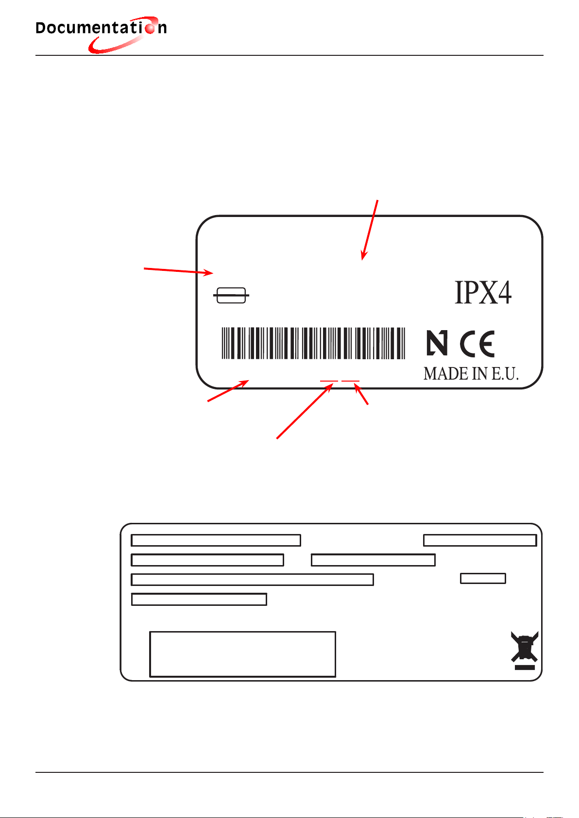
Specications plate (Registration plate)
This is situated on the hatch on the front of the washing machine. This plate indicates
the following:
FAGOR F-1810
COD.905014763
0905014763080200001
2200W 220-230V-50Hz
10A. 4.9-98N/cm2
NIF ESF20020517
N.080200001
TYPWM-900E3B
Mains voltage and frequency
Month of manufacture
Year of manufacture
Washing machine
code (9 digits)
Total power
REGISTRATION PLATE
MAKE AND MODEL
WASHING MACHINE CODE
SERIAL NUMBER
POWER, VOLTAGE AND FREQUENCY
MAINS WATER PRESSURE
BARCODE
TYPE OF APPLIANCE
CAPACITY
OFFICIAL APPROVAL SYMBOLS AND OTHERS
Page 6

Features
t e c h n i c a l
3
+
AA
A dv a nc e d B al an c e S ys t e m
kg
10 0 0 rpm
8
400
700
1000
3h
6h
9h
Stop
Select
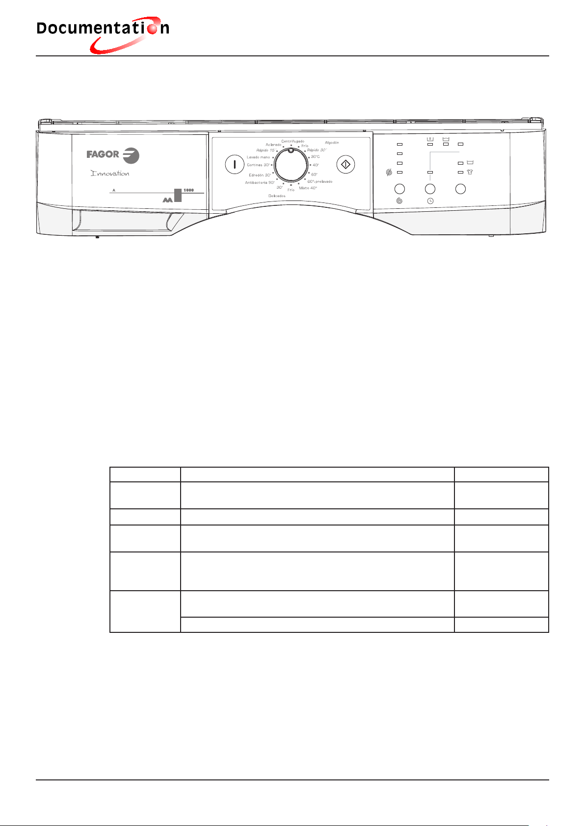
2.- Features
This range comprises of the following models:
Button
ON/OFF
Drawer for
detergent
Programme
selector
Start/pause
button
Spin + flot
button
Time delay
button
Additional
functions
button
Wash programmes
For washing machines manufactured after 1st of May 2007
PROGRAMMES V1 circuits
NORMAL DELICATE FABRICS SPECIAL
1 Normal cold 7 Delicate Mixed 40ºC 10 Antibacterial 90ºC
2 Fast 30ºC 8 Delicate cold 11 Eiderdown 30ºC
3 Normal 30ºC 9 Delicate 30ºC 12 Curtains 30ºC
4 Normal 40ºC 13 Hand wash
5 Normal 60ºC 14 Quick (15 minutes)
6 Pre-wash 60ºC 15 Rinses
16 Spin
LB6W302A1 Circuit
Page 7
Description of operation
t e c h n i c a l
4
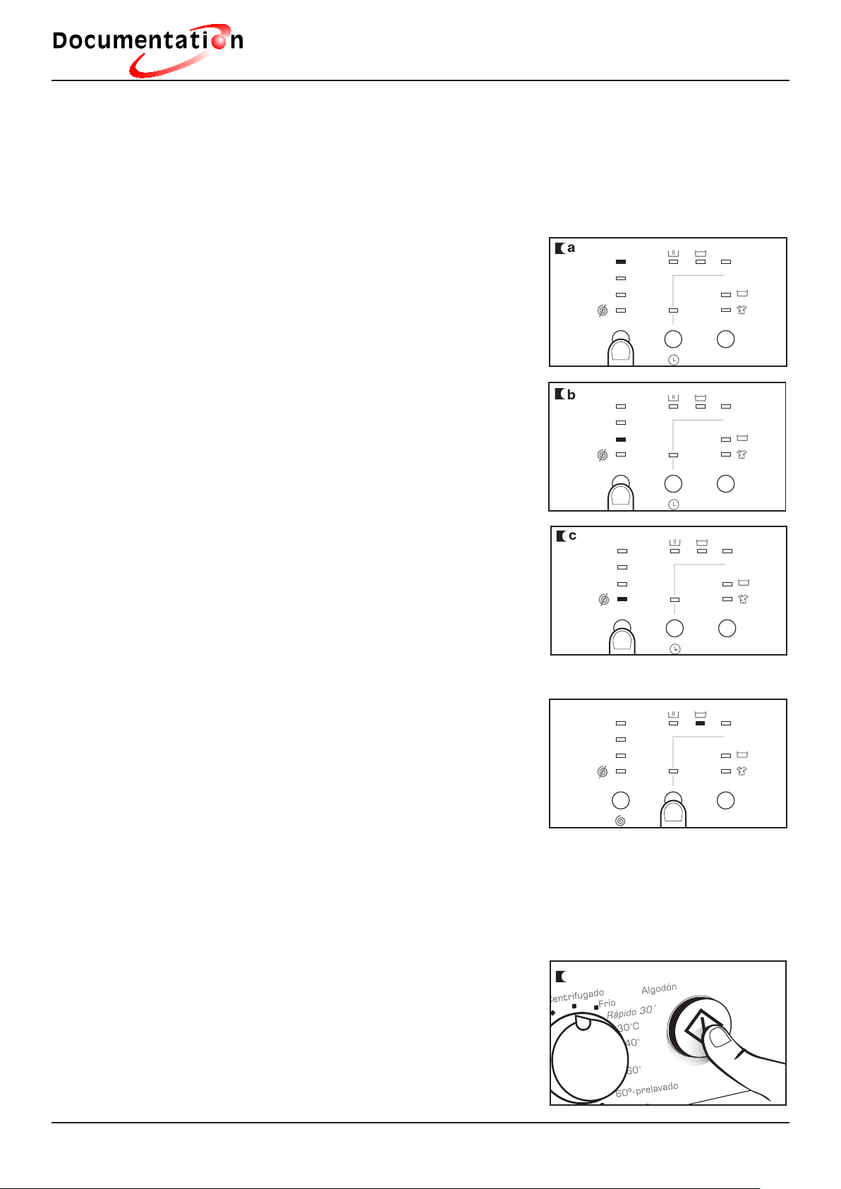
Spin
The wash options must always be selected after selecting the wash programme.
Any change to the programme carried out during
the selection cancels the options which were
previously selected.
a) Spin selection button. The selected programme
has an associated spin speed in revolutions per
minute, and the corresponding spin speed pilot light
turns on.
b) To change the speed, press the spin button
repeatedly, and the appropriate pilot light will
light up.
c) Skip spin option. Press the spin button once
more to reach the skip spin option. This programme
is used to prevent creases from forming in special
fabrics, as it has no nal spin.
Time delay option
Time delay selection button
A delay of up to 9 hours may be selected. The
delay must be selected after choosing the wash
programme. To select the time delay in hours,
choose 3, 6 or 9 hours.
Cancel time delay
To cancel the delay, press the time delay button until the pilots indicating the delay
go off. Changing to another programme also cancels the delay.
Start
Start/Pause button
a) To start the washing machine you must press the
start/stop key.
400
700
1000
3h
6h
9h
Stop
Select
400
700
1000
3h
6h
9h
Stop
Select
400
700
1000
3h
6h
9h
Stop
Select
400
700
1000
3h
6h
9h
Stop
Select
400
700
1000
3h
6h
9h
Stop
Select
a
Page 8

Description of operation
t e c h n i c a l
5
Additional functions
Button for selecting additional functions according to programmes.
There are 2 options: anti-crease and intensive wash.
Press the button to display the required option.
By pressing several times, you can choose
between various combinations of one or two
additional functions at the same time, depending
on the chosen programme.
Key: Anti-crease
This stops at the nal rinse, leaving the clothing oating in water. When the function is
deactivated, the washer continues the programme, draining and spinning.
This is used when you are not at home, for example, to delay the spin until you have
arrived so that creases are not caused by the clothes being spun and then left in
the drum.
Key: Intensive Wash
This option, specially recommended for very dirty or stained garments, gives better
results by lengthening the wash cycle.
Programme progress
When the programme is running, the pilot lights indicate the current programme phase.
Any option button may be selected, as long as the
wash phase in which it takes effect has not passed,
and when the programme permits that option.
Pressing the delay button during the wash has no
effect on the washer.
Pressing the Start/Pause button during the wash
puts the washer in the PAUSE state.
Important: If, during the wash cycle, the programme is changed using the selector,
the washer is left in the PAUSE state, and the programme is canceled. To add or
remove an article, press the start/pause button and make sure that the water is not
above the door overow level, and that the interior temperature is not high. Press the
start/pause button again to re-start the washer from the same phase of the cycle in
which it was stopped.
400
700
1000
3h
6h
9h
Stop
Select
400
700
1000
3h
6h
9h
Stop
Select
Page 9

Description of operation
t e c h n i c a l
6
Power failure
When the supply returns after a power failure, the washer continues to work as normal,
from the point at which it stopped (its memory lasts a few hours).
The same thing happens if the ON/OFF button is pressed.
Warnings
To reduce the noise level of the spin cycle: use the adjustable feet to level the washer.
Aim to wash clothes of different sizes in the same wash programme, for a better
weight distribution in the drum when spinning.
All the models have a spin cycle safety system, which prevents them spinning if the
distribution of the clothes in the drum is very uneven. This prevents excessive vibration.
If at any time the clothes have not been correctly spun, spread them out more evenly
in the drum, and spin again.
Page 10

Description of operation
t e c h n i c a l
7
3.- Description of operation
3.1.- General description
3.1.1.- Component characteristics
Component Function Features
Motor
1250 RPM
Used in machines
with variable spin,
and makes rotating
movements when
washing and spinning.
Motor power supply:
- Clockwise, power
220 V., contacts 2
and 3. Bridge between
contacts 5 and 6.
- Anti-clockwise, power
220 V. , contacts 3
and 5. Bridge between
contacts 2 and 6.
Voltage: 220 v / 50 Hz
Stator resistance: 1.3 Ω
Rotor resistance: 1.7 Ω
Tachogenerator resistance:
184 Ω
Tachogenerator voltage:
1.2 v / 1,000 rpm
Double field motor
1400 RPM
Used in machines
with variable spin,
and makes rotating
movements when
washing and spinning.
Motor power supply:
- Clockwise, power
220 V, contacts 4
and 5. Bridge between
contacts 3 and 6.
- Anti-clockwise, power
220 V, contacts 4
and 6. Bridge between
contacts 5 and 3.
Voltage: 220 v / 50 Hz
Stator resistance: 3.3 Ω
Rotor resistance: 2.46 Ω
Tachogenerator resistance:
90 Ω
Door lock Opens hatch lock. Voltage: 220 v / 50 Hz
16 Amp.
Delay of between 40 and
75 seconds.
2
4'
34!4/2
4(%2-)#
02/4%#4/2
34!4/2
4'
2
4(%2-!,
02/4%#4/2
Page 11

Description of operation
t e c h n i c a l
8
Component Function Features
Door lock with
instant opening
Hatch closing
Manual opening for use
in case of electricity
supply failure
Recirculation pump Recirculates the water
in the drum for greater
wash effectiveness
and reduced
programme times
Voltage: 220-240 v / 50 Hz
Drainage pump resistance
170 Ω
Recirculation pump
resistance 180 Ω
Both have a thermal
protector
Power 30 W
Double connectorised
electrovalve
Allows water intake in
the pre-wash, wash and
rinse phases
EV1 pre-wash orange
connector
EV2 wash black
connector
EV1 + EV2 additive
intake
Voltage: 220-240 V /50 Hz
Power: 5 W
Flow: 6.7 litres / minute
Pressure: 0.5-10 kg / cm²
Resistance: R1=R2=R3=
3.7K Ω
3/4 Thread Gas
12mm conduit diameter
Pressure switch The pressure gauge
is activated in the
following conditions:
- When the wash level
reaches 12 litres. (11-12)
- When the level
exceeds 33 litres
(overflow), the drainage
pump is activated
(safety). (11-16)
- The rinse level is
performed according
to the time of the
microprocessor of the
electronic card.
Level 1
102 / 72 ± 3
Overflow safety device
310 ± 10
11
12
14
16
12 Water inlet
14 Heating
16 Overflow
11 Common
Page 12

Description of operation
t e c h n i c a l
9
Component Function Features
Heating resistance Heating element
+ thermofuse
incorporated into the
element itself
Thermofuse cut-out
temperature165ºC
Resistance: 26.4 Ω
Material: Austenitic
stainless steel
Power: 2022 W
Voltage: 230 v
NTC ≤ 30ºC variable
resistance value 9786 Ω
V1 electronic circuit Power and display
circuit
Voltage: 220 v / 50 Hz
Important: It is necessary
to configure the circuit
before starting the machine.
(follow configuration
instructions)
Page 13

Description of operation
t e c h n i c a l
10
3.1.2.- Conguration of the V1circuits
1. ON/OFF switch turned off.
2. Press the Start/Pause button and keep it pressed.
3. Press ON/OFF button until the STOP LED lights up.
4. While still holding down the Start/Pause button, press the spin button until the
Wash, Rinse, and STOP LEDS light up. Then immediately release the Start/Pause
button and spin buttons at the same time.
5. Press the spin button once, and the circuit conguration LEDS will light up (must
match the sticker attached to the body of the tray).
6. To change the conguration of:
* Speed: press the speed button until the LED or LEDs match the sticker.
* Cold water: Press the time delay button. The LED must be off.
* RH: press the Select button until the Flot and Intensive LEDS light up.
7. To conrm the conguration, press the Start/Pause button until the Skip Spin Option,
Time Delay and Select LEDs start to ash.
+
AA
A dv a nc e d B al an c e S ys t e m
kg
10 0 0 rpm
8
400
700
1000
3h
6h
9h
Stop
Select
CONTROL PANEL BARCODE REFERENCE
Page 14
Description of operation
t e c h n i c a l
11
3.1.3- T.S.S. Programme
1. ON/OFF switch turned off.
2. Press the Start/Pause key and keep it pressed.
3. Press ON/OFF switch until the STOP LED lights up.
4. While still holding down the Start/Pause button, press the spin button until the
Wash, Rinse, and STOP LEDs are lit up. Then immediately release the Start/Pause
button and spin buttons at the same time.
5. Press the spin button once, and the circuit conguration LEDs will light up (must
match the sticker attached to the body of the tray).
6. To conrm the conguration, press the Start/Pause button until the Skip Spin Option,
Time Delay and Select LEDs start to ash.
The circuit then carries out the T.S.S. programme and the wash LED lights up.
LED SELECTION MODE TIME (APPROX.)
WASH Water intake via Pre-wash Electrically-operated valve +
Movement of wash motor at 55 rpm
10 sec.
RINSES Emptying + Spin 5 min.
STOP Water inlet via the electrically operated valve for Washing
until wash level is reached
Pressure switch
level
EXTRA
RINSE
The element starts to heat up until it reaches 40ºC +
Intermittent recirculation - 90 sec. not activated and 30 sec.
activated
40ºC
INTENSIVE Water input via pre-wash, wash and softener electrically-
operated valves + Recirculation
5 sec.
Drainage Pump 30 sec.
+
AA
A dv a nc e d B al an c e S ys t e m
kg
10 0 0 rpm
8
400
700
1000
3h
6h
9h
Stop
Select
Page 15

Description of operation
t e c h n i c a l
12
Fault modes description table
T.S.S. programme fast forward function: Press the start / pause button to move to another step in the programme without rst having to nish the step.
SAFETY
MECHANISMS
FAULTS ACTIONS RESET (Security end)
FILLING EV activated for 8 min
and without water
Wash and rinse LEDs flashing
The machine stops with the door lock activated All options are reset if:
1.- Power is lost (unplugged or ON/OFF)
2.- Selector position is changed
3.- If, when the programme finishes, the start button is
pressed
DOOR OPEN - Washing machines with instant-opening door lock:
At the beginning of the programme, the circuit detects that the door is not closed
- Washing machines with PTC door lock:
If the door lock is without power for
8 seconds the fault is displayed
Wash and STOP LEDs flashing, alternating
IN USER PROGRAMME
STOP (Programme end)
All options are reset if:
1.- Power is lost (unplugged or ON/OFF)
2.- Selector position is changed
3.- Door is closed
(IF THE CIRCUIT IS IN A SPECIAL PROGRAMME
(AP_01, AP_01, REP_01 OR SAT) IN RESET IT
RETURNS TO STATUS A)
EMPTYING EB ON 6min.
and PN ON (full). Rinse and STOP LEDs flashing
STOP (Programme end) All options are reset if:
1.- Power is lost (unplugged or ON/OFF)
2.- Change of position of the selector
OVERFLOW The fault is displayed:
If the pressure switch detects that the washing machine is too full
If the pump connector is broken or is not connected
Wash, rinse, STOP and intensive wash LEDs flashing
NTC NTC in short circuit or open circuit
Wash, rinse, STOP and spin LEDs flashing
The programme ends without heating the water
DOES NOT
HEAT UP
ß < 5°C/15min.
(Except in reliability program)
Wash, rinse, STOP and SKIP spin (0) LEDs flashing
MOTOR Tachogenerator failure, motor blocked
- The wash programme is stopped for 120 seconds
- The error counter starts counting
- If the error counter counts 3 faults, the error code F08 is displayed
- When the stop time is exceeded, the programme begins again
If the error does not occur in the next 20 seconds the error counter is reset. The
programme stops (in any instance) and starts again in the same position. If the error
occurs in the spin phase the programme will start the whole spin sequence again from
the start.
This error returns to the initial conditions if the error is reset.
Wash, rinse, STOP and Flot LEDs flashing.
STOP (Programme end)
Door lock always activated
The same as the previous ones but with the door lock
activated
MOTOR
INVERSION
FAULT
The drum rotation direction does not change until the motor stops
(max. time 2 min.)
Wash, rinse, STOP and extra intensive rinse LEDs flashing
WARNING CHECK ACTION RESET
UNBALANCED If an imbalance is detected when it makes 18 attempts to spin or during 15 minutes
of attempts
Wash and rinse LEDs flashing and STOP alternating
The washing machine spins at the lowest
revolution
The fault is reset in the following way:
1.- Cutting off the power (unplugged or ON/OFF)
2.- Change selector position
Page 16

Description of operation
t e c h n i c a l
13
3.1.4.- Washing machine vibrations
• Wash vibrations
VERY DELICATE SPIN
SEMI-DELICATE SPIN
DELICATE SPIN
SUPER SPIN
SPIN PLUS
T.S.S. SPIN
FLOT SPIN (maximum time 2 hours)
NORMAL SPIN
EXTRA SPIN
SEC.
SEC.
SEC.
SEC.
SEC.
SEC.
SEC.
SEC.
SEC.
NON-DETECTION
OF OVERFLOW AREA
ANTI-CLOCKWISE
CLOCKWISE
Page 17

Description of operation
t e c h n i c a l
14
• Spin vibrations
Easy iron
NORMAL SPIN AND EASY IRON/WASHING MACHINES E2002
EASY IRON PHASE 1 EASY IRON PHASE 2 EASY IRON PHASE 3
IMBALANCE TEST
IMBALANCE TEST
IMBALANCE TEST 1 and 2
IMBALANCE TEST 1 and 2
MACHINE MODEL
RPM
selector
EASY IRON PHASE 0
Page 18

Description of operation
t e c h n i c a l
15
Normal spin:
NORMAL SPIN PHASE 0
MACHINE MODEL
Step 7
Step 6
Step 5
Step 4
Step 3
Step 2
Step 1
Step 0
IMBALANCE TEST 1, 2, 3
According to programme
SEC.
RPM Selector Settings
Page 19

Description of operation
t e c h n i c a l
16
3.1.5.- Spin attempts
If the washing machine detects the unequal balance of clothes in the spin cycle it will
follow this process:
The total number of attempts to start spinning is 20, divided according to these criteria.
In the rst 6 attempts, the maximum unbalanced limit allowed is 550 g.
Between the 7th and 18th attempts the maximum unbalanced limit allowed is 800 g
and the nal speed is less than the nominal speed, for example a washing machine
of 1,200 rpm will spin at 1,000 rpm.
For the 19th and 20th attempts, the maximum unbalanced limit allowed is 1,500 g,
and the nal spin speed will be 650 rpm, except in washing machines with a nominal
speed of 700 rpm, which will spin at 400 rpm.
These attempts to reposition the clothes in the drum will increase the total programme
time by 20 minutes.
The LCD screen will display CO3. This is not considered a fault, it merely warns the
user about the security measure the circuit has detected.
If an imbalance is detected in the rinse phase the number of attempts will not exceed 3.
In 8 kg washers dating from after 01/11/2007, the number of imbalance correction
attempts is reduced by half (9 attempts).
Page 20

Description of operation
t e c h n i c a l
17
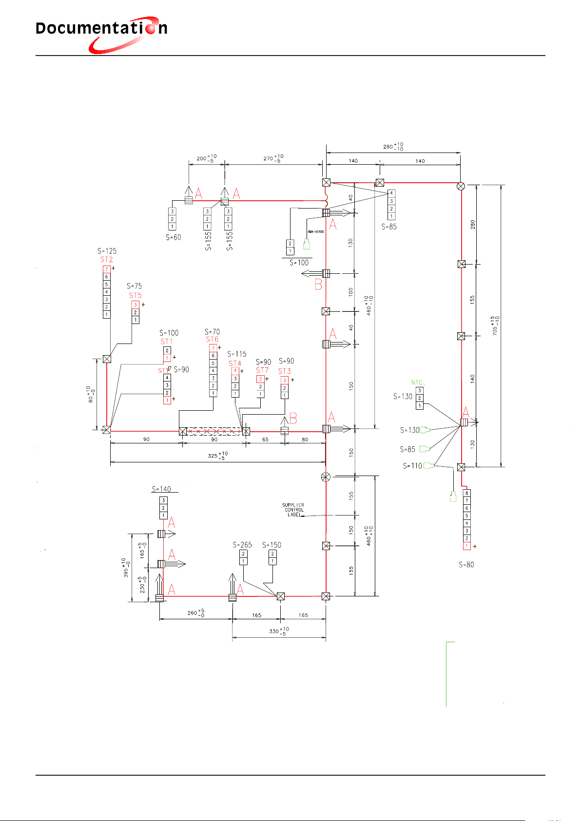
3.2.- Drawings and diagrams
Page 21
Description of operation
t e c h n i c a l
18
DOOR LOCK
RECIRCULATION
PUMP
DRAIN
PUMP
E.V.3 HOT WATER
E.V.1 PRE-WASH
E.V.2 WASH
FILTER
PRESSURE SWITCH
RESISTANCE
FUSE
MOTOR
AMA–GREEN
AMA–GREEN
Page 22

© FAGOR ELECTRODOMESTICOS, S.COOP. 2008
Bº San Andrés, s/n
20500 Mondragón (Gipuzkoa)
España (Spain)
 Loading...