

Page 1

CNC
8055 ·MC·
Operating manual
Ref.1705
Soft: V02.2x
Page 2

This product uses the following source code, subject to the terms of the GPL license. The applications busybox V0.60.2;
dosfstools V2.9; linux-ftpd V0.17; ppp V2.4.0; utelnet V0.1.1. The librarygrx V2.4.4. The linux kernel V2.4.4. The linux boot
ppcboot V1.1.3. If you would like to have a CD copy of this source code sent to you, send 10 Euros to Fagor Automation
for shipping and handling.
All rights reserved. No part of this documentation may be transmitted,
transcribed, stored in a backup device or translated into another language
without Fagor Automation’s consent. Unauthorized copying or distributing of this
software is prohibited.
The information described in this manual may be subject to changes due to
technical modifications. Fagor Automation reserves the right to change the
contents of this manual without prior notice.
All the trade marks appearing in the manual belong to the corresponding owners.
The use of these marks by third parties for their own purpose could violate the
rights of the owners.
It is possible that CNC can execute more functions than those described in its
associated documentation; however, Fagor Automation does not guarantee the
validity of those applications. Therefore, except under the express permission
from Fagor Automation, any CNC application that is not described in the
documentation must be considered as "impossible". In any case, Fagor
Automation shall not be held responsible for any personal injuries or physical
damage caused or suffered by the CNC if it is used in any way other than as
explained in the related documentation.
The content of this manual and its validity for the product described here has been
verified. Even so, involuntary errors are possible, hence no absolute match is
guaranteed. However, the contents of this document are regularly checked and
updated implementing the necessary corrections in a later edition. We appreciate
your suggestions for improvement.
The examples described in this manual are for learning purposes. Before using
them in industrial applications, they must be properly adapted making sure that
the safety regulations are fully met.
DUAL-USE PRODUCTS
Products manufactured by FAGOR AUTOMATION since April 1st 2014 will
include "-MDU" in their identification if they are included on the list of dual-use
products according to regulation UE 428/2009 and require an export license
depending on destination.
Page 3
Operating manual
CNC 8055
CNC 8055i
SOFT: V02.2X
·3·
INDEX
About the product ......................................................................................................................... 5
Version history .............................................................................................................................. 7
Safety conditions ........................................................................................................................ 11
Returning conditions ................................................................................................................... 15
Declaration of conformity and Warranty conditions .................................................................... 17
Additional notes .......................................................................................................................... 19
Fagor documentation.................................................................................................................. 21
CHAPTER 1 GENERAL CONCEPTS
1.1 Keyboard........................................................................................................................ 23
1.2 General concepts........................................................................................................... 25
1.2.1 P999997 text program management.......................................................................... 28
1.3 Power-up........................................................................................................................ 29
1.4 Working in M mode with the MC keyboard .................................................................... 30
1.5 Video off......................................................................................................................... 30
1.6 Managing the CYCLE START key................................................................................. 30
CHAPTER 2 OPERATING IN JOG MODE
2.1 Introduction .................................................................................................................... 32
2.1.1 Standard screen of the MC mode .............................................................................. 32
2.1.2 Special screen of the MC mode ................................................................................. 34
2.1.3 Standard screen of the MC mode. Configuration of two and half axes...................... 36
2.1.4 Selecting a program for simulation or execution ........................................................ 38
2.2 Axis control .................................................................................................................... 39
2.2.1 Work units .................................................................................................................. 39
2.2.2 Coordinate preset....................................................................................................... 39
2.2.3 Managing the axis feedrate (F) .................................................................................. 39
2.3 Machine reference (home) search ................................................................................. 40
2.4 Zero offset table ............................................................................................................. 41
2.5 Jog movement ............................................................................................................... 42
2.5.1 Moving an axis to a particular position (coordinate)................................................... 42
2.5.2 Incremental movement............................................................................................... 42
2.5.3 Continuous jog ........................................................................................................... 43
2.5.4 Path-jog...................................................................................................................... 44
2.5.5 Movement with an electronic handwheel ................................................................... 46
2.5.6 Feed handwheel......................................................................................................... 47
2.5.7 Path-handwheel ......................................................................................................... 48
2.6 Tool control .................................................................................................................... 49
2.6.1 Tool change ............................................................................................................... 51
2.6.2 Variable tool change point.......................................................................................... 53
2.7 Tool calibration............................................................................................................... 54
2.7.1 Define the tool in the tool table (level 1)..................................................................... 55
2.7.2 Tool calibration without a probe (level 1) ................................................................... 57
2.7.3 Tool calibration with a probe (level 2) ........................................................................ 59
2.7.4 Part centering with / without a probe (level 3) ............................................................ 61
2.7.5 Tabletop probe calibration (level 4)............................................................................ 65
2.8 Spindle control ............................................................................................................... 67
2.9 Controlling the external devices..................................................................................... 68
2.10 ISO management........................................................................................................... 69
CHAPTER 3 WORKING WITH OPERATIONS OR CYCLES
3.1 Operation editing mode.................................................................................................. 73
3.1.1 Definition of machining conditions.............................................................................. 74
3.1.2 Safety plane ...............................................................................................................75
3.1.3 Cycle level.................................................................................................................. 76
3.2 Simulating and executing the operation......................................................................... 77
3.2.1 Background cycle editing ........................................................................................... 78
3.3 Profile milling operation.................................................................................................. 79
3.3.1 Definition of data ........................................................................................................ 80
3.3.2 Profile definition (level 2)............................................................................................ 82
3.4 Surface milling and slot milling operations..................................................................... 83
3.4.1 Defining the surface milling data ................................................................................ 84
3.4.2 Defining the grooving data ......................................................................................... 85
Page 4

·4·
Operating manual
CNC 8055
CNC 8055i
SOFT: V02.2X
3.5 Pocket cycle with a profile ............................................................................................. 87
3.5.1 Definition of data ........................................................................................................ 89
3.5.2 Profile definition .........................................................................................................90
3.5.3 Profile definition examples ......................................................................................... 91
3.6 Rectangular and circular boss cycles ............................................................................ 96
3.6.1 Definition of data ........................................................................................................ 97
3.7 Rectangular and circular pocket cycles ......................................................................... 99
3.7.1 Definition of data ...................................................................................................... 101
3.8 Positioning (2 levels).................................................................................................... 103
3.8.1 Definition of data ...................................................................................................... 104
3.9 Boring operation .......................................................................................................... 105
3.9.1 Definition of data ...................................................................................................... 106
3.10 Reaming operation ...................................................................................................... 107
3.10.1 Definition of data ...................................................................................................... 108
3.11 Tapping operation........................................................................................................ 109
3.11.1 Definition of data (threading).................................................................................... 110
3.11.2 Definition of data (thread milling) ............................................................................. 112
3.12 Drilling and center punching operations ...................................................................... 114
3.12.1 Definition of data ...................................................................................................... 116
3.12.2 Tool withdrawal ........................................................................................................ 117
3.13 Multiple positioning ...................................................................................................... 118
3.13.1 Multiple positioning in several locations ................................................................... 120
3.13.2 Multiple positioning in a straight line ........................................................................ 121
3.13.3 Multiple positioning in an arc.................................................................................... 122
3.13.4 Multiple positioning in a rectangular pattern ............................................................ 124
3.13.5 Multiple positioning in a grid pattern ........................................................................ 125
CHAPTER 4 OPERATING IN ISO MODE
4.1 Editing blocks in ISO mode.......................................................................................... 128
4.2 Programming assistance ............................................................................................. 129
4.2.1 Zero offsets and presets .......................................................................................... 129
4.2.2 Work zones .............................................................................................................. 129
4.2.3 Insert labels and repetitions from label to label........................................................ 129
4.2.4 Mirror image............................................................................................................. 130
4.2.5 Scaling factor ........................................................................................................... 130
4.2.6 Coordinate rotation .................................................................................................. 130
4.2.7 Plane change ........................................................................................................... 131
CHAPTER 5 SAVING PROGRAMS
5.1 List of saved programs ................................................................................................ 134
5.2 See the contents of a program .................................................................................... 135
5.2.1 Seeing one of the operations in detail...................................................................... 136
5.3 Edit a new part-program .............................................................................................. 137
5.4 Saving an ISO block or a cycle.................................................................................... 138
5.5 Delete a new part program .......................................................................................... 139
5.6 Copying a part-program into another one .................................................................... 140
5.7 Modify a part-program ................................................................................................. 141
5.7.1 Delete an operation.................................................................................................. 142
5.7.2 Add or insert a new operation .................................................................................. 143
5.7.3 Move an operation to another position..................................................................... 144
5.7.4 Modify an existing operation .................................................................................... 145
5.8 Managing programs using the explorer ....................................................................... 146
CHAPTER 6 EXECUTION AND SIMULATION
6.1 Simulating or executing an operation or cycle ............................................................. 148
6.2 Simulating or executing a part-program....................................................................... 149
6.2.1 Simulating or executing a portion of a part-program ................................................ 150
6.3 Simulating or executing an operation that has been saved ......................................... 151
6.4 Execution mode ........................................................................................................... 152
6.4.1 Tool inspection......................................................................................................... 153
6.5 Graphic representation ................................................................................................ 154
Page 5

CNC 8055
CNC 8055i
·5·
ABOUT THE PRODUCT
BASIC CHARACTERISTICS OF THE DIFFERENT MODELS.
HARDWARE OPTIONS OF THE 8055I CNC
8055i FL EN 8055 FL
8055i FL
8055 Power
8055i Power
Pendant 8055i FL EN 8055i FL 8055i Power
Enclosure ----- 8055 FL 8055 Power
USB Standard Standard Standard
Block processing time 1 ms 3.5 ms 1 ms
RAM memory 1Mb 1Mb 1 Mb
Software for 7 axes ----- ----- Option
TCP transformation ----- ----- Option
C axis (Lathe) ----- ----- Option
Y axis (Lathe) ----- ----- Option
Look-ahead 100 blocks 100 blocks 200 blocks
Flash Memory 512Mb / 2Gb 512Mb Option Option
Analog Digital Engraving
Ethernet Option Option Option
RS232 serial line. Standard Standard Standard
16 digital inputs and 8 outputs (I1 to I16 and O1 to O8) Standard Standard Standard
Another 40 digital inputs and 24 outputs (I65 to I104 and O33 to O56) Option Option Option
Probe inputs Standard Standard Standard
Spindle (feedback input and analog output) Standard Standard Standard
Electronic handwheels Standard Standard Standard
4 axes (feedback and velocity command) Option Option - - -
Remote CAN modules, for digital I/O expansion (RIO). Option Option - - -
Sercos servo drive system for Fagor servo drive connection. - - - Option - - -
CAN servo drive system for Fagor servo drive connection. - - - Option - - -
Before start-up, verify that the machine that integrates this CNC meets the 89/392/CEE Directive.
Page 6
·6·
CNC 8055
CNC 8055i
About the product
SOFTWARE OPTIONS OF THE 8055 AND 8055I CNCS.
Model
GP M MC MCO EN T TC TCO
Number of axes with standard software 4 4 4 4 3 2 2 2
Number of axes with optional software 7 7 7 7 ----- 4 or 7 4 or 7 4 or 7
Electronic threading ----- Stand. Stand. Stand. Stand. Stand. Stand. Stand.
Tool magazine management: ----- Stand. Stand. Stand. ----- Stand. Stand. Stand.
Machining canned cycles ----- Stand. Stand. ----- Stand. Stand. Stand. -----
Multiple machining ----- Stand. Stand. ----- Stand. ----- ----- -----
Solid graphics ----- Stand. Stand. Stand. ----- Stand. Stand. Stand.
Rigid tapping ----- Stand. Stand. Stand. Stand. Stand. Stand. Stand.
Tool life monitoring ----- Opt. Opt. Opt. Stand. Opt. Opt. Opt.
Probing canned cycles ----- Opt. Opt. Opt. Stand. Opt. Opt. Opt.
DNC Stand. Stand. Stand. Stand. Stand. Stand. Stand. Stand.
COCOM version Opt. Opt. Opt. Opt. ----- Opt. Opt. Opt.
Profile editor Stand. Stand. Stand. Stand. ----- Stand. Stand. Stand.
Tool radius compensation Stand. Stand. Stand. Stand. Stand. Stand. Stand. Stand.
Tangential control Opt. Opt. Opt. Opt. ----- Opt. Opt. Opt.
Retracing ----- Opt. Opt. Opt. Stand. Opt. Opt. Opt.
Setup assistance Stand. Stand. Stand. Stand. Stand. Stand. Stand. Stand.
Irregular pockets with islands ----- Stand. Stand. Stand. ----- ----- ----- -----
TCP transformation ----- Opt. Opt. Opt. ----- ----- ----- -----
C axis (on Lathe) ----- ----- ----- ----- ----- Opt. Opt. Opt.
Y axis (on Lathe) ----- ----- ----- ----- ----- Opt. Opt. Opt.
Telediagnosis Opt. Opt. Opt. Opt. Stand. Opt. Opt. Opt.
Page 7

CNC 8055
CNC 8055i
·7·
VERSION HISTORY
Here is a list of the features added in each software version and the manuals that describe them.
The version history uses the following abbreviations:
INST Installation manual
PRG Programming manual
OPT Operating manual
OPT-MC Operating manual for the MC option.
OPT-TC Operating manual for the TC option.
OPT-CO Manual of the CO manual
Software V01.00 October 2010
First version.
Software V01.20 April 2011
Software V01.08 August 2011
Software V01.30 September 2011
List of features Manual
Open communication. INST
Improvements to Look Ahead machining. INST
Blocks with helical interpolation in G51. PRG
G84. Tapping with relief. PRG
List of features Manual
Spindle parameter OPLDECTI (P86). INST
List of features Manual
Gear ratio management on Sercos spindles INST
Improved feedrate limit management (FLIMIT). INST
New type of penetration in lathe type threading cycles. PRG
Improved lathe type thread repair. Partial repair. PRG
MC option: Rigid tapping with relief. OPT-MC
TC option: New type of penetration in threading cycles. OPT-TC
TC option: Improved thread repair. Partial and multi-entry (start) thread repair. OPT-TC
TC option: Zig-zag entry to the groove at the starting point of the groove. OPT-TC
Page 8

·8·
CNC 8055
CNC 8055i
Version history
Software V01.31 October 2011
Software V01.40 January 2012
Software V01.60 December 2013
Software V01.65 January 2015
Software V02.00 February 2014
List of features Manual
CNC 8055 FL Engraving model INST / OPT/ PRG
List of features Manual
Execution of M3, M4 and M5 using PLC marks INST / PRG
Values 12 and 43 of variable OPMODE in conversational work mode. INST / PRG
List of features Manual
Auto-adjustment of axis machine parameter DERGAIN. INST
New value for axis machine parameter ACFGAIN (P46). INST
Value 120 of the OPMODE variable. INST / PRG
List of features Manual
Block processing time of 1 ms on the "CNC 8055i FL Engraving" model. INST / OPT/ PRG
List of features Manual
Profile machining in segments. J parameter for G66 and G68 cycles. PRG
Calls to subroutines using G functions. INST / PRG
Anticipated tool management. INST
Managing "PNG" and "JPG" graphic elements. INST
New values for parameters MAXGEAR1..4 (P2..5), SLIMIT (P66) and MAXSPEED (P0). INST
Retracing function of 2000 blocks. INST
Quick block search. OPT
Local subroutines within a program. PRG
Avoid spindle stop with M30 or RESET. Spindle parameter SPDLSTOP (P87). INST
Programming T and M06 with associated with a subroutine in the same line. PRG
New values of the OPMODE variable. INST / PRG
New variables: DISABMOD, GGSN, GGSO, GGSP, GGSQ, CYCCHORDERR. INST / PRG
Possibility to set the parameters of SERCOS nodes in a non-sequential order. INST
WRITE instruction: “$” character followed by “P”. PRG
Cancel additive handwheel offset with G04 K0. General parameter ADIMPG (P176). INST / PRG
Ethernet parameter NFSPROTO (P32). TCP or UDP protocol selection. INST
Face thread repair cycle. OPT TC
Penetration increment (step) in thread repair. INST / OPT TC
API compliant thread. OPT TC
Roughing by segments in inside profiling cycles 1 and 2. INST / OPT TC
Programming the Z increment and the angle on threads. INST / OPT TC
Reversal of the starting and final point of the face thread repair. INST / OPT TC
Manual tool calibration without stopping the spindle during each step. INST / OPT TC
Page 9

CNC 8055
CNC 8055i
·9·
Version history
Software V02.03 July 2014
Software V02.10 November 2014
Software V02.21 July 2015
Software V02.22 March 2016
List of features Manual
Set PAGE and SYMBOL instructions support PNG and JPG/JPEG formats. PRG
New values for parameters MAXGEAR1..4 (P2..5), SLIMIT (P66), MAXSPEED (P0) and
DFORMAT (P1).
INST
List of features Manual
Incremental zero offset (G158). INST / PRG
Programs identified with letters. OPT
Variables PRGN and EXECLEV. INST
Korean language. INST
Change of default value for general machine parameters: MAINOFFS (P107), MAINTASF (P162)
and FEEDTYPE (P170).
INST
New variable EXTORG. INST / PRG
Image handling via DNC. PRG
Save/restore a trace of the oscilloscope. OPT
List of features Manual
PLC library. INST
Zero offsets table in ISO mode. OPT
Compensation of the elastic deformation in the coupling of an axis. INST
Machine axis parameter DYNDEFRQ (P103). INST
Change of maximum value of axis and spindle parameter NPULSES. INST
List of features Manual
Axis filters for movements with the handwheel. General machine parameter HDIFFBAC (P129)
and machine axis parameter HANFREQ (P104).
INST
Change of maximum value of axis and spindle parameter NPULSES. INST
Page 10

·10·
CNC 8055
CNC 8055i
Version history
Page 11

CNC 8055
CNC 8055i
·11·
SAFETY CONDITIONS
Read the following safety measures in order to prevent harming people or damage to this product and those
products connected to it.
The unit can only be repaired by personnel authorized by Fagor Automation.
Fagor Automation shall not be held responsible of any physical or material damage originated from not
complying with these basic safety rules.
PRECAUTIONS AGAINST PERSONAL HARM
• Interconnection of modules.
Use the connection cables provided with the unit.
• Use proper Mains AC power cables
To avoid risks, use only the Mains AC cables recommended for this unit.
• Avoid electric shocks.
In order to avoid electrical discharges and fire hazards, do not apply electrical voltage outside the range
selected on the rear panel of the central unit.
• Ground connection.
In order to avoid electrical discharges, connect the ground terminals of all the modules to the main
ground terminal. Before connecting the inputs and outputs of this unit, make sure that all the grounding
connections are properly made.
• Before powering the unit up, make sure that it is connected to ground.
In order to avoid electrical discharges, make sure that all the grounding connections are properly made.
• Do not work in humid environments.
In order to avoid electrical discharges, always work under 90% of relative humidity (non-condensing)
and 45 ºC (113º F).
• Do not operate this unit in explosive environments.
In order to avoid risks, harm or damages, do not work in explosive environments.
Page 12

·12·
CNC 8055
CNC 8055i
Safety conditions
PRECAUTIONS AGAINST PRODUCT DAMAGE
• Work environment.
This unit is ready to be used in industrial environments complying with the directives and regulations
effective in the European Community.
Fagor Automation shall not be held responsible for any damage that could suffer or cause when installed
under other conditions (residential or domestic environments).
• Install this unit in the proper place.
It is recommended, whenever possible, to install the CNC away from coolants, chemical product, blows,
etc. that could damage it.
This unit meets the European directives on electromagnetic compatibility. Nevertheless, it is
recommended to keep it away from sources of electromagnetic disturbance, such as:
Powerful loads connected to the same mains as the unit.
Nearby portable transmitters (radio-telephones, Ham radio transmitters).
Nearby radio / TC transmitters.
Nearby arc welding machines.
Nearby high voltage lines.
Etc.
•Enclosures.
It is up to the manufacturer to guarantee that the enclosure where the unit has been installed meets
all the relevant directives of the European Union.
• Avoid disturbances coming from the machine tool.
The machine-tool must have all the interference generating elements (relay coils, contactors, motors,
etc.) uncoupled.
DC relay coils. Diode type 1N4000.
AC relay coils. RC connected as close to the coils as possible with approximate values of R=220
1 W y C=0,2 µF / 600 V.
AC motors. RC connected between phases, with values of R=300 / 6 W y C=0,47 µF / 600 V.
• Use the proper power supply.
Use an external regulated 24 Vdc power supply for the inputs and outputs.
• Connecting the power supply to ground.
The zero Volt point of the external power supply must be connected to the main ground point of the
machine.
• Analog inputs and outputs connection.
It is recommended to connect them using shielded cables and connecting their shields (mesh) to the
corresponding pin.
• Ambient conditions.
The working temperature must be between +5 ºC and +40 ºC (41ºF and 104º F)
The storage temperature must be between -25 ºC and +70 ºC. (-13 ºF and 158 ºF)
• Monitor enclosure (CNC 8055) or central unit ( CNC 8055i)
Guarantee the required gaps between the monitor or the central unit and each wall of the enclosure.
Use a DC fan to improve enclosure ventilation.
• Power switch.
This power switch must be mounted in such a way that it is easily accessed and at a distance between
0.7 meters (27.5 inches) and 1.7 meters (5.5ft) off the floor.
Page 13

CNC 8055
CNC 8055i
·13·
Safety conditions
PROTECTIONS OF THE UNIT ITSELF (8055)
• "Axes" and "Inputs-Outputs" modules.
All the digital inputs and outputs have galvanic isolation via optocouplers between the CNC circuitry
and the outside.
They are protected by an external fast fuse (F) of 3.15 A 250V against overvoltage of the external power
supply (over 33 Vdc) and against reverse connection of the power supply.
• Monitor.
The type of protection fuse depends on the type of monitor. See identification label of the unit itself.
PROTECTIONS OF THE UNIT ITSELF (8055I)
• Central unit.
It has a 4 A 250V external fast fuse (F).
• Inputs-Outputs.
All the digital inputs and outputs have galvanic isolation via optocouplers between the CNC circuitry
and the outside.
OUT
IN
X7
X1
X8
X9
X2
X10
X3
X11X4X12
X5
X13
X6
+24V
0V
FUSIBLE
FUSES
Page 14

·14·
CNC 8055
CNC 8055i
Safety conditions
PRECAUTIONS DURING REPAIRS
SAFETY SYMBOLS
• Symbols that may appear in the manual.
Do not manipulate the inside of the unit. Only personnel authorized by Fagor Automation may access
the interior of this unit.
Do not handle the connectors with the unit connected to AC power. Before manipulating the connectors
(inputs/outputs, feedback, etc.) make sure that the unit is not connected to AC power.
Symbol for danger or prohibition.
It indicates actions or operations that may cause damage to people or to units.
Warning or caution symbol.
It indicates situations that could be caused by certain operations and the actions to take to prevent
them.
Mandatory symbol.
It indicates actions or operations that MUST be carried out.
Information symbol.
It indicates notes, warnings and advises.
i
Page 15

CNC 8055
CNC 8055i
·15·
RETURNING CONDITIONS
When sending the central nit or the remote modules, pack them in its original package and packaging
material. If you do not have the original packaging material, pack it as follows:
1. Get a cardboard box whose 3 inside dimensions are at least 15 cm (6 inches) larger than those of the
unit itself. The cardboard being used to make the box must have a resistance of 170 kg. (375 pounds).
2. Attach a label indicating the owner of the unit, person to contact, type of unit and serial number.
3. In case of failure, also indicate the symptom and a short description of the failure.
4. Protect the unit wrapping it up with a roll of polyethylene or with similar material.
5. When sending the central unit, protect especially the screen.
6. Pad the unit inside the cardboard box with polyurethane foam on all sides.
7. Seal the cardboard box with packaging tape or with industrial staples.
Page 16

·16·
CNC 8055
CNC 8055i
Returning conditions
Page 17

CNC 8055
CNC 8055i
·17·
DECLARATION OF CONFORMITY AND
WARRANTY CONDITIONS
DECLARATION OF CONFORMITY
The declaration of conformity for the CNC is available in the downloads section of FAGOR’S corporate
website at http://www.fagorautomation.com. (Type of file: Declaration of conformity).
WARRANTY TERMS
The warranty conditions for the CNC are available in the downloads section of FAGOR’s corporate website
at http://www.fagorautomation.com. (Type of file: General sales-warranty conditions).
Page 18

·18·
CNC 8055
CNC 8055i
Declaration of conformity and Warranty conditions
Page 19

CNC 8055
CNC 8055i
·19·
ADDITIONAL NOTES
Mount the CNC away from coolants, chemical products, blows, etc. which could damage it. Before turning
the unit on, verify that the ground connections have been made properly.
To prevent electrical shock at the central unit of the 8055 CNC, use the proper mains AC connector at the
power supply module. Use 3-wire power cables (one for ground connection).
To prevent electrical shock at the monitor of the 8055 CNC, use the proper mains AC connector (A) with
3-wire power cables (one of them for ground connection).
Before turning on the monitor of the 8055 CNC and verifying that the external AC line (B) fuse of each unit
is the right one. See identification label of the unit itself.
In case of a malfunction or failure, disconnect it and call the technical service. Do not get into the inside
of the unit.
FAGOR
I/O
X1
X2
X3
AXES
X1 X2
X3 X4
X5 X6
X7 X8
X9
X10
CPU
X1 X2
CMPCT
FLASH
ETH
COM1
X3
C
D
E
F
0
B
A
9
8
1
7
2
6
3
5
4
IN
OUT
NODE
USB
(A)
(B)
X1
W1
Page 20

·20·
CNC 8055
CNC 8055i
Additional notes
Page 21

CNC 8055
CNC 8055i
·21·
FAGOR DOCUMENTATION
OEM manual
It is directed to the machine builder or person in charge of installing and starting-up the CNC.
USER-M manual
Directed to the end user.
It describes how to operate and program in M mode.
USER-T manual
Directed to the end user.
It describes how to operate and program in T mode.
MC Manual
Directed to the end user.
It describes how to operate and program in MC mode.
It contains a self-teaching manual.
TC Manual
Directed to the end user.
It describes how to operate and program in TC mode.
It contains a self-teaching manual.
MCO/TCO model
Directed to the end user.
It describes how to operate and program in MCO and TCO mode.
Examples-M manual
Directed to the end user.
It contains programming examples for the M mode.
Examples-T manual
Directed to the end user.
It contains programming examples for the T mode.
WINDNC Manual
It is directed to people using the optional DNC communications software.
It is supplied in a floppy disk with the application.
WINDRAW55 Manual
Directed to people who use the WINDRAW55 to create screens.
It is supplied in a floppy disk with the application.
Page 22

·22·
CNC 8055
CNC 8055i
Fagor documentation
Page 23

CNC 8055
CNC 8055i
·MC· OPTION
SOFT: V02.2X
1
·23·
GENERAL CONCEPTS
1.1 Keyboard
Alphanumeric keyboard and command keys
Specific keys of the MC model
Select the X character.
Select the A character.
Select the R character.
These keys may be used for:
• Selecting and defining the machining operations.
• Govern the external devices.
• Selecting the spindle work mode.
• Selecting the single block or automatic execution Mode.
Page 24

·24·
Operating manual
CNC 8055
CNC 8055i
1.
GENERAL CONCEPTS
·MC· OPTION
SOFT: V02.2X
Keyboard
JOG keys
These keys may be used for:
• Moving the axes of the machine.
• Governing the spindle.
• Modifying the feedrate of the axes and the spindle speed.
• Starting and stopping the execution.
Page 25

Operating manual
CNC 8055
CNC 8055i
GENERAL CONCEPTS
1.
·MC· OPTION
SOFT: V02.2X
·25·
General concepts
1.2 General concepts
It offers all the features of the M model plus those specific of the MC mode. For example, the CNC
setup must be done in M mode.
In MC work mode, programs P900000 through P999999 are reserved for the CNC itself; in other
words, the user cannot use them as part-programs.
On the other hand, in order to work in MC mode, the CNC must have programs P999997 and
P999998 stored in its memory. Both programs are related to the software version and, consequently,
are not supplied by Fagor Automation. Whenever the CNC detects a new software version , it updates
these programs automatically and, for safety, it makes a copy of the old ones in the KeyCF.
Likewise, subroutines 0000 through 8999 are free to use and subroutines 9000 through 9999 are
reserved for the CNC.
Subroutines reserved for the CNC
Some of the subroutines reserved for the CNC have the following meaning:
Both subroutines must be defined by the machine manufacturer, even when no operation is to be
carried out at the beginning and at the end of the part-program. If they are not defined, the CNC
will issue an error message when trying to execute a part-program.
OEM (manufacturer's) parameters
OEM parameters and subroutines with OEM parameters can only be used in OEM programs; those
defined with the [O] attribute. Modifying one of these parameters in the tables requires an OEM
password.
When using OEM parameters in the configuration programs, this program must have the [O]
attribute; otherwise, the CNC will issue an error when editing the user cycles that refer to OEM
parameters in write mode.
Programs P999997 and P999998 are associated with the software version. Fagor Automation shall
not be held responsible of the CNC's performance if programs P999997 and P999998 have been
deleted from memory or do not match the software version.
9998 Subroutine that the CNC will execute at the beginning of each part-program.
9999 Subroutine that the CNC will execute at the end of each part-program.
Every time a new part-program is edited, the CNC inserts a call to the relevant
subroutine at the beginning and at the end of the program.
Example of how to define subroutine 9998.
(SUB 9998) ; Definition of subroutine 9998.
··· ; Program blocks defined by the OEM.
(RET) ; End of subroutine.
Page 26

·26·
Operating manual
CNC 8055
CNC 8055i
1.
GENERAL CONCEPTS
·MC· OPTION
SOFT: V02.2X
General concepts
Programs reserved for the CNC
Some of the programs reserved for the CNC have the following meaning:
P999998
It is a program of subroutines that the CNC uses to interpret the programs edited in MC format and
execute them later on.
P999997
It is a text program that contains:
• The sentences and texts that will be displayed on the various screens of the MC mode.
• The help texts for the icons, in the work cycles, that are shown on the lower left side of the screen.
• The messages (MSG) and errors (ERR) that may come up at the MC model.
All the texts, messages and errors that may be translated into the desired language.
Considerations about the texts.
The format of a line is as follows:
;Text number - explanatory comment (not displayed) - $Text to be displayed
All the program lines must begin with the ";" character and the text to be displayed must be preceded
by the "$" symbol. If a line begins with ";;", the CNC assumes that the whole line is a program
comment.
Examples:
;44 $M/MIN Is message 44 and displays the text "M/MIN"
;;General text The CNC treats it as a comment
;;44 Feedrate $M/MIN The CNC treats it as a comment
;44 Feedrate $M/MIN Is message 44 whose hidden explanatory comment is
"Feedrate" and displays the text "M/MIN"
Considerations about the messages.
The format must be respected. Only the text after SAVEMSG may be translated:
Example:
Original message: N2002(MSG"SAVEMSG: DRILLING 1")
Translated message: N2002(MSG"SAVEMSG: 1 ZULAKETA ZIKLOA")
This program must not be modified. If this program is modified or deleted, Fagor Automation will not
be held responsible of the CNC's performance.
If the manufacturer needs to create his own subroutines (for home search, tool change, etc.), as well
as subroutines 9998 and 9999, they must be included in another program, for example P899999.
When modifying program 999997, it is recommended to make a backup copy of it because the CNC
replaces that program when selecting another language or updating the software version.
i
Page 27

Operating manual
CNC 8055
CNC 8055i
GENERAL CONCEPTS
1.
·MC· OPTION
SOFT: V02.2X
·27·
General concepts
Considerations about the errors.
The format must be respected. Only the text between quote marks ("text") may be translated.
Example:
Original text: N1021(ERROR"TALADRADO 1: F=0")
Translated text: N1001(ERROR"1 ZULAKETA ZIKLOA: F=0")
P998000 ··· P998999
They are the profiles for the pocket-with-profile cycle that are defined by the user with the profile
editor. In the MC mode, the user defines them with 3 digits (from 0 to 999) and the CNC saves them
internally as P998xxx.
P997000 ··· P997999
They are the profiles for the profile milling operation that are defined by the user with the profile edi tor.
In the MC mode, the user defines them with 3 digits (from 0 to 999) and the CNC saves them internally
as P997xxx.
Page 28

·28·
Operating manual
CNC 8055
CNC 8055i
1.
GENERAL CONCEPTS
·MC· OPTION
SOFT: V02.2X
General concepts
1.2.1 P999997 text program management
On power up, the CNC copies the texts of program P999997 into the system memory.
• It checks if program P999997 is in user memory, if not, it looks in the KeyCF and if it is not there
either, it assumes the default ones and copies them into program P999997 of the user memory.
• When selecting mainland Chinese, it ignores program P999997 and it always assumes the
default ones.
If when switching from M mode to MC or MCO mode, it cannot find program P999997 because it
has been deleted, it is initialized like on power-up.
When modifying the texts of program P999997, turn the CNC off and back on so it assumes the
new texts.
The CNC carries out the following operations when changing the language, the software version
and when adding MC, MCO conversational modes (new software features):
• It copies, for safety, the texts that were being used into KeyCF as program P999993.
• It deletes the program P999997 that may be in the KeyCF.
• It assumes the new texts that are provided by default and copies them into program P999997
of the user memory.
To change the texts, after modifying program P999997, turn the CNC off and back on so it assumes
the new texts.
Page 29

Operating manual
CNC 8055
CNC 8055i
GENERAL CONCEPTS
1.
·MC· OPTION
SOFT: V02.2X
·29·
Power-up
1.3 Power-up
The standard screen of the MC mode is the following:
On power-up and after the keystroke sequence [SHIFT] [RESET], the CNC shows
"page 0" defined by the manufacturer; if there is no "page 0", it shows the standard
screen of the work mode. Press any key to access the work mode.
There are 2 work modes: MC work mode and M work mode. Press the key
sequence [SHIFT] [ESC] to go from one work mode to the other.
The CNC setup must be done in M mode.
Likewise, some errors must be eliminated in M mode.
Page 30

·30·
Operating manual
CNC 8055
CNC 8055i
1.
GENERAL CONCEPTS
·MC· OPTION
SOFT: V02.2X
Working in M mode with the MC keyboard
1.4 Working in M mode with the MC keyboard
The MC keyboard is designed to also be able to work in M mode. In M mode, use the alphanumeric
keyboard and the keys that replace the softkeys F1 through F7.
1.5 Video off
Also, any message (PLC, program, etc.) restores the CNC image.
1.6 Managing the CYCLE START key
In order to avoid undesired executions when pressing key sequences that are not supported in MC
mode, the CNC changes the "Start" icon at the top of the window from green to gray and shows a
message indicating that it is an invalid action.
For example, if "M3 Start" is pressed (sequence not supported in MC mode) while a part-program
is selected, the CNC issues a warning and prevents the selected part-program from running when
detecting the "Start" key.
There are 2 work modes: MC work mode and M work mode. Press the key
sequence [SHIFT] [ESC] to go from one work mode to the other.
Alphanumeric keyboard:
The keys that replace the softkeys F1 through F7
are:
The keystroke sequence [SHIFT] [CLEAR] clears the CRT screen (it goes blank).
Press any key to restore the image.
Page 31

CNC 8055
CNC 8055i
·MC· OPTION
SOFT: V02.2X
2
·31·
OPERATING IN JOG MODE
The standard screen of the MC mode is the following:
When pressing the two-color key, the CNC shows the special screen of the MC mode.
Page 32

·32·
Operating manual
CNC 8055
CNC 8055i
2.
OPERATING IN JOG MODE
·MC· OPTION
SOFT: V02.2X
Introduction
2.1 Introduction
2.1.1 Standard screen of the MC mode
The standard screen of the MC mode offers the following data:
1. Clock.
2. This window may show the following data:
SBK when "single block" execution mode is selected.
DNC when the DNC mode is active.
P..... Number of the program currently selected.
Message "In position" - "Execution" - "Interrupted" - "RESET".
PLC messages.
3. This window shows the CNC messages.
4. This window may show the following data:
X, Y, Z coordinates of the axes.
In small characters, the axis coordinates referred to machine reference zero. These values are
useful when letting the user define a tool change point (see zone 6) The CNC shows this data
when text 33 of program 999997 has not been defined.
The coordinates of the auxiliary axes that are defined.
The real spindle rpm.
5. The information shown in this window depends on the position of the left switch.
In all cases, it shows the axis feedrate "F" currently selected and the % of F being applied.
When feed-hold is active, the color of the feedrate value changes.
Page 33

Operating manual
CNC 8055
CNC 8055i
OPERATING IN JOG MODE
2.
·MC· OPTION
SOFT: V02.2X
·33·
Introduction
Here are all the possible cases.
6. This window shows, in large characters, the selected tool number "T" and, in small characters,
the "D" offset associated with the tool. If the tool number and the offset number are the same,
the CNC will not show the "D" value.
This window also shows the coordinates of the tool change point referred to machine reference
zero. The CNC does not show this window when text 47 of program 999997 has not been defined.
7. This window shows everything related to the spindle:
The real spindle speed "S".
The spindle status. It is represented with an icon and may be turning cl ockwise, counterclockwise
or stopped.
The % of spindle speed being applied.
The active spindle speed gear (range). The CNC does not show this data when text 28 of program
999997 has not been defined.
8. When accessing a work cycle, this window shows the help text associated with the selected icon.
That help text must be defined in program P999997 and edited in the desired language. See
chapter "1 General concepts".
9. Reserved.
Displaying the active PLC messages
At the screen, press [+] of the alphanumeric keyboard, the CNC shows a window with all the active
PLC messages. Besides, this window is also displayed whenever there is a program in execution.
The [] [] [PG UP] [PG DW] keys are used to move around the messages. The [ESC] key is used
to close the window.
The window is only displayed when there are more than one active message.
Direct access to the oscilloscope
The oscilloscope may be accessed from the standard screen by pressing "7" and then "1" as long
as no data is being written into any field.
Page 34

·34·
Operating manual
CNC 8055
CNC 8055i
2.
OPERATING IN JOG MODE
·MC· OPTION
SOFT: V02.2X
Introduction
2.1.2 Special screen of the MC mode
The special screen of the MC mode offers the following data:
1. Clock.
2. This window may show the following data:
SBK when "single block" execution mode is selected.
DNC when the DNC mode is active.
P..... Number of the program currently selected.
Message "In position" - "Execution" - "Interrupted" - "RESET".
PLC messages.
3. This window shows the CNC messages.
4. This window shows the lines of the program currently selected.
5. The X, Y, Z axes have the following fields:
The spindle (S) has the following fields:
The auxiliary axes only show the real current position of the axis.
COMMAD It indicates the programmed coordinate or position that the axis
must reach.
ACTUAL It indicates the actual (current) position of the axis.
TO GO It indicates the distance which is left to run to the programmed
coordinate.
FOLLOWING ERROR Difference between the theoretical value and the real value of
the position.
THEORETICAL Programmed theoretical S speed.
RPM Speed in rpm.
M/MIN Speed in meters per minute.
FOLLOWING ERROR When working with spindle orientation (M19), it indicates the
difference between the theoretical and the real speeds.
Page 35

Operating manual
CNC 8055
CNC 8055i
OPERATING IN JOG MODE
2.
·MC· OPTION
SOFT: V02.2X
·35·
Introduction
6. This window shows the status of the "G" functions and the auxiliary "M" functions that are active.
Likewise, it shows the value of the variables.
7. Reserved.
8. Reserved.
Displaying the active PLC messages
At the screen, press [+] of the alphanumeric keyboard, the CNC shows a window with all the active
PLC messages. Besides, this window is also displayed whenever there is a program in execution.
The [] [] [PG UP] [PG DW] keys are used to move around the messages. The [ESC] key is used
to close the window.
The window is only displayed when there are more than one active message.
Direct access to the oscilloscope
The oscilloscope may be accessed from the auxiliary screen by pressing "7" and then "1" as long
as no data is being written into any field.
PARTC It indicates the number of consecutive parts executed with the same part-
program.
Every time a new program is selected, this variable is reset to "0".
CYTIME It indicates the time elapsed while executing the part. It is given in "hours: minutes:
seconds: hundredths of a second" format.
Every time a part-program execution starts, even when repetitive, this variable is
reset to "0".
TIMER It indicates the count of the timer enabled by PLC. It is given in "hours: minutes:
seconds" format.
Page 36

·36·
Operating manual
CNC 8055
CNC 8055i
2.
OPERATING IN JOG MODE
·MC· OPTION
SOFT: V02.2X
Introduction
2.1.3 Standard screen of the MC mode. Configuration of two and half axes
A two-and-a-half-axis configuration is a milling machine where the X and Y axes are motorized and
the Z axis is set as a DRO axis (display only). In this configuration, the Z axis is moved manually.
The CNC interface for this type of configuration looks like this.
Editing and execution
The cycles are edited, stored and simulated just like a 3-axis configuration.
The most significant different lays in the execution because the operator must move the Z axis by
hand. The standard screen shows the operations to be carried out by the operator. In each case,
it shows the status of the Z axis and the various actions to be executed by the operator.
• Move Z up (it shows an icon next to the final Z coordinate).
The operator must move the axis up manually. When the Z axis is in position, the message will
change.
• Move Z down (it shows an icon next to the final Z coordinate).
The operator must move the axis down manually. When the Z axis is in position, the message
will change.
• Press CYCLE START.
The operator must press [CYCLE START] to begin the X-Y movement in automatic.
•Moving in X-Y.
The machine is moving in X-Y. When a Z axis move is required, the machine will stop and it will
request the operator's intervention.
• Tool inspection.
It went into tool inspection.
Page 37

Operating manual
CNC 8055
CNC 8055i
OPERATING IN JOG MODE
2.
·MC· OPTION
SOFT: V02.2X
·37·
Introduction
Canned cycles
Not all the cycles can be applied to a two-and-a-half-axis configuration. The following cycles are
permitted. In some of these cycles, some data has been eliminated to adapt them to the two-anda-half-axis configuration. This data referred to operations of the Z axis.
• Positioning 1 and 2.
• Profile milling and profile 1 milling.
• Surface milling.
• Slot milling.
• 2D profile pocket.
• Rectangular and circular boss.
• Simple, rectangular and circular pocket 1 and 2.
• Center punching.
• Drilling 1.
• Reaming.
• Boring 1 and 2.
• Multiple positioning, point to point, linear, in arc 1 and 2, in grid and rectangular patterns.
Page 38

·38·
Operating manual
CNC 8055
CNC 8055i
2.
OPERATING IN JOG MODE
·MC· OPTION
SOFT: V02.2X
Introduction
2.1.4 Selecting a program for simulation or execution
When selecting a part-program or operation saved as part of a part-program for simulation or
execution, the CNC selects that part-program and shows it highlighted next to the green "start"
symbol in the top center window.
When the top center window shows the part-program selected next to the green "start" symbol, the
CNC acts as follows:
• If [START] is pressed, the CNC executes the part-program that is selected.
• If [CLEAR] is pressed, the CNC de-selects the part-program and removes it from the top center
window.
Page 39

Operating manual
CNC 8055
CNC 8055i
OPERATING IN JOG MODE
2.
·MC· OPTION
SOFT: V02.2X
·39·
Axis control
2.2 Axis control
2.2.1 Work units
When accessing the MC mode, the CNC assumes the work units "mm or inches", "mm/min. or
mm/rev", etc. selected by machine parameter.
To modify those values, access the M mode and change the corresponding machine parameter.
2.2.2 Coordinate preset
The coordinates must be preset on one axis at a time proceeding as follows:
1. Press the key of the desired axis, [X], [Y] or [Z].
The CNC will highlight the coordinate of that axis indicating that it is selected.
2. Key in the value to preset the axis.
To quit the preset mode, press [ESC].
3. Press [ENTER] for the CNC to assume that value as the new value for the point.
The CNC requests confirmation of the command. Press the [ENTER] to confirm it or [ESC] to
quit the preset mode.
2.2.3 Managing the axis feedrate (F)
To set a particular axis feedrate value, proceed as follows:
1. Press the [F] key.
The CNC will highlight the current value that it is selected.
2. Key in the desired new feedrate value.
To quit the preset selection mode, press [ESC].
3. Press [START] for the CNC to assume that value as the new value for axis feedrate.
Page 40

·40·
Operating manual
CNC 8055
CNC 8055i
2.
OPERATING IN JOG MODE
·MC· OPTION
SOFT: V02.2X
Machine reference (home) search
2.3 Machine reference (home) search
Home search may be done in 2 ways:
• Homing all the axes.
• Homing a single axis.
Homing all the axes
To home all the axes, press [ZERO].
The CNC requests confirmation of the command (text 48 of program 999997). Press [START], the
CNC will execute the home search subroutine defined by the OEM in general machine parameters
P34 (REFPSUB).
Homing a single axis
To home a single axis, press the key of the desired axis and the key for home search.
In either case, the CNC requests confirmation of the command (text 48 of program 999997).
After searching home this way, the CNC will maintain the part zero or zero offset active at the time.
A home search subroutine (general machine parameter P34 other than 0) must be defined when using
this method. Otherwise, the CNC will display the corresponding error.
i
It homes the X axis.
It homes the Y axis.
It homes the Z axis.
After searching home this way, the CNC will not maintain the par t zero or zero offset active at the time
and assumes the machine reference zero as the new part zero.
i
Page 41

Operating manual
CNC 8055
CNC 8055i
OPERATING IN JOG MODE
2.
·MC· OPTION
SOFT: V02.2X
·41·
Zero offset table
2.4 Zero offset table
It is possible to manage the zero offset table from the conversational mode (G54.... G59, G159N7
... G159N20). This table contains the same values as that of the conversational mode.
Press the [ZERO] key to access the zero offset table as well as to get out of it. The zero offset table
may be accessed in the following ways.
• From the standard screen, as long as no axis is selected. The CNC will request confirmation
of the command.
• From ISO mode, when the "zero offsets and presets" cycle is selected.
The zero offset table looks like this. It shows all the offsets, PLC offset included, and their value in
each axis.
When scrolling the focus through the table, the elements appear in different colors as follows.
How to edit the table data
The following operations are possible in the zero offset table. Press [ENTER] to validate any
changes.
• Editing a zero offset.
It is edited one axis at a time. Select a data with the focus and edit its value. If the magnifying
glass is placed on top of an offset (G54 ... G59, G159N7 ... G159N20), editing start on the first
axis of that offset.
• Load the active zero offset into the table.
Position the magnifying glass over the offset you wish to define (G54 ... G59, G159N7 ...
G159N20) and click on the [RECALL] key. The active preset is saved in the selected zero offset.
If instead of placing the focus on a zero offset, it is placed on one of the axes, only that axis will
be affected.
• Deleting a zero offset.
Position the magnifying glass over the offset that you wish to erase (G54 ... G59, G159N7 ...
G159N20) and click on the [CLEAR] key. All the axes of that zero offset are reset to zero.
If instead of placing the focus on a zero offset, it is placed on one of the axes, only that axis will
be affected.
Color Meaning
Green background.
Text in white.
The real value of the table and the value shown on the screen are the same.
Red background.
White text.
The real value of the table and the value shown on the screen are NOT the same.
The value on the table has been changed, but it has not been validated. Press
[ENTER] to validate the change.
Blue background. The zero offset is active.
Two origins may be active simultaneously, one absolute (G54 ... G57, G159N7
... G159N20) and another incremental (G58-G59).
Page 42

·42·
Operating manual
CNC 8055
CNC 8055i
2.
OPERATING IN JOG MODE
·MC· OPTION
SOFT: V02.2X
Jog movement
2.5 Jog movement
When making a move in manual, both in jog and with handwheels, the moving axis appears in
reverse video.
• With gantry axes, only the master axis is highlighted.
• With a path handwheel, no axis is highlighted; but it is in path-jog.
2.5.1 Moving an axis to a particular position (coordinate)
The movements of axes to a particular coordinate are made one at a time as follows.
2.5.2 Incremental movement
Turn the JOG switch to one of the JOG positions.
The incremental movement must be made one axis at a time. To do that, press the JOG keys for
the direction of the axis to be jogged.
Every time a key is pressed, the corresponding axis moves the amount set by the switch. This
movement is made at the selected feedrate (F).
[target coordinate]
[target coordinate]
[target coordinate]
Switch position Distance
1 0.001 mm or 0.0001 inches
10 0.010 mm or 0.0010 inches
100 0.100 mm or 0.0100 inches
1000 1.000 mm or 0.1000 inches
10000 10.000 mm or 1.0000 inches
Page 43

Operating manual
CNC 8055
CNC 8055i
OPERATING IN JOG MODE
2.
·MC· OPTION
SOFT: V02.2X
·43·
Jog movement
2.5.3 Continuous jog
Place the movement selector in the continuous-jog position and select at the feedrate override switch
(FEED) the percentage (0% to 120%) of the feedrate to be applied.
The continuous jog must be made one axis at a time. To do that, press the JOG keys for the direction
of the axis to be jogged.
The axis moves at a feedrate equal to the selected percentage (0% to 120%) of feedrate "F".
Depending on the status of the general logic input "LATCHMAN", the movement will be carried out
as follows:
• If the PLC sets this mark low, the axis will be jogged while pressing the corresponding Jog key.
• If the PLC sets this mark high, the axes will start moving from the moment the JOG key is pressed
until the same is pressed again, or another JOG key is pressed. In this case, the movement will
be transferred to that indicated by the new key.
The following cases are possible when working with "F" in mm/rev:
• The spindle is running.
• The spindle is stopped, but a spindle speed S has been selected.
• The spindle is stopped and no spindle speed S has been selected.
The spindle is running.
The spindle is stopped, but a spindle speed S has been selected.
The spindle is stopped and no spindle speed S has been selected.
If while jogging an axis, the rapid key is pressed, the axis will move at the maximum
feedrate possible, set by axis machine parameter "G00FEED". This feedrate will be
applied while that key is kept pressed and the previous feedrate will be restored when
that key is released.
The CNC moves the axes at the programmed F.
The CNC calculates the feedrate F in mm/min for the theoretical S and moves
the axis.
For example if "F 2.000" and "S 500":
F (mm/min) = F (mm/rev) x S (mm/rev) = 2 x 500 = 1000 mm/min.
The axis moves at a feedrate of 1000 mm/min.
If F = 0, the CNC moves the axes in rapid.
If F is other than 0, the axes can only be moved by pressing the rapid key and
an axis key. The CNC moves the axis in rapid.
Page 44

·44·
Operating manual
CNC 8055
CNC 8055i
2.
OPERATING IN JOG MODE
·MC· OPTION
SOFT: V02.2X
Jog movement
2.5.4 Path-jog
The "path jog" mode acts when the switch is in one of the continuous or incremental jog positions.
This feature may be used to act upon the jog keys of an axis to move both axes of the plane at the
same time for chamfering (straight sections) and rounding (curved sections). The CNC assumes
as "Path jog" the keys associated with the X axis.
While in jog mode and having selected path-jog, the CNC shows the following information:
For a linear movement (top figure), the path angle must be defined and for an arc (bottom figure),
the center coordinates must be indicated. To define these variables, press the [F] key and then one
of these keys: [] [] [] [].
Operation in path-jog mode
The "path jog" mode is only available with the X axis keys. When pressing one of the keys associated
with the X axis, the CNC behaves as follows:
The rest of the jog keys always work in the same way, whether "path jog" is on or off. The rest of
the keys move only the axis and in the indicated direction.
The movements in path-jog may be aborted by pressing the [STOP] key or setting the jog switch
to one of the handwheel positions.
This feature must be managed from the PLC. This feature is usually activated and deactivated by
means of an external push-button or a key configured for that purpose, as well as the selection of the
type of path.
i
The next example uses the [O2] key to activate and deactivate the path-jog mode and the
[O3] key to indicate the type of movement.
Activate / deactivate the path-jog mode.
DFU B29 R561 = CPL M5054
It selects the type of movement, straight section or arc section.
DFU B31 R561 = CPL M5053
Switch position Path-jog Type of movement
Continuous jog Deactivated Only the axis and in the indicated direction
Activated Both axes in the indicated direction and along the indicated
path
Incremental jog Deactivated Only the axis, the selected distance and in the indicated
direction
Activated Both axes, the selected distance and in the indicated
direction, but along the indicated path
Handwheel It ignores the keys.
Page 45

Operating manual
CNC 8055
CNC 8055i
OPERATING IN JOG MODE
2.
·MC· OPTION
SOFT: V02.2X
·45·
Jog movement
Considerations about the jog movements
This mode assumes as axis feedrate the one selected in jog mode and it will also be affected by
the feedrate override switch. If F0 is selected, it assumes the one indicated by machine parameter
"JOGFEED (P43)". This mode ignores the rapid jog key.
Path-jog movements respect the travel limits and the work zones.
Page 46

·46·
Operating manual
CNC 8055
CNC 8055i
2.
OPERATING IN JOG MODE
·MC· OPTION
SOFT: V02.2X
Jog movement
2.5.5 Movement with an electronic handwheel
This option may be used to govern the movements of the machine using an electronic handwheel.
To do that, turn the left switch to any of the handwheel positions.
The positions available are 1, 10 and 100; they indicate the multiplying factor being applied besides
the internal x4 to the feedback pulses supplied by the electronic handwheel.
The machine has an electronic handwheel
Once the desired switch position has been selected, press one of the JOG keys for the axis to be
jogged. The bottom of the screen shows the selected axis in small characters and next to the
handwheel symbol.
When using a FAGOR handwheel with an axis selector button, the axis may be selected as follows:
• Push the button on the back of the handwheel. The CNC select the first axis and it highlights it.
• When pressing the button again, the CNC selects the next axis and so on in a rotary fashion.
• To deselect the axis, hold the button pressed for more than 2 seconds.
Once the axis has been selected, it will move as the handwheel is being turned and in the direction
indicated by it.
The machine has two or three electronic handwheels
Each axis will move as the corresponding handwheel is being turned according to th e switch position
and in the direction indicated by it.
When the machine has a general handwheel and individual handwheels (associated with each axis
of the machine), the individual handwheels have the highest priority; i.e. when moving an individual
handwheel, the CNC will ignore the general handwheel.
Switch position Distance per turn
1 0.100 mm or 0.0100 inches
10 1.000 mm or 0.1000 inches
100 10.000 mm or 1.0000 inches
It may happen that depending on the turning speed and the selector switch position, the CNC be
demanded a faster feedrate than the maximum allowed (axis machine parameter "G00FEED"). The
CNC will move the axis the indicated distance but at the maximum feedrate allowed.
i
Page 47

Operating manual
CNC 8055
CNC 8055i
OPERATING IN JOG MODE
2.
·MC· OPTION
SOFT: V02.2X
·47·
Jog movement
2.5.6 Feed handwheel
Usually, when making a part for the first time, the machine feedrate is controlled by means of the
feedrate override switch.
From this version on, it is also possible to use the machine handwheels to control that feedrate. This
way, the machining feedrate will depend on how fast the handwheel is turned.
The following CNC variables return the number of pulses the handwheel has turned.
HANPF provides the number of pulses of the 1st handwheel.
HANPS provides the number of pulses of the 2nd handwheel.
HANPT provides the number of pulses of the 3rd handwheel.
HANPFO provides the number of pulses of the 4th handwheel.
This feature must be managed from the PLC. Usually, this feature is turned on and off using an external
push button or key configured for that purpose.
i
Page 48

·48·
Operating manual
CNC 8055
CNC 8055i
2.
OPERATING IN JOG MODE
·MC· OPTION
SOFT: V02.2X
Jog movement
2.5.7 Path-handwheel
The "path handwheel" mode acts when the switch is in one of the handwheel positions. With this
feature, it is possible to jog two axes of the plane at the same time along a linear path (chamfer)
or circular path (rounding) with a single handwheel. The CNC assumes as the path handwheel the
general handwheel or, when this one is missing, the one associated with the X axis.
While in handwheel mode and having selected path-handwheel, the CNC shows the following
information:
For a linear movement (top figure), the path angle must be defined and for an arc (bottom figure),
the center coordinates must be indicated. To define these variables, press the [F] key and then one
of these keys: [] [] [] [].
Operation in path-handwheel mode
When selecting the path handwheel mode, the CNC behaves as follows.
• If there is a general handwheel, it will be the one working in path handw heel mode. The individual
handwheels, if any, will remain associated with the corresponding axes.
• If there is no general handwheel, the individual handwheel associated with the X axis then works
in path-handwheel mode.
The movements in path-handwheel may be aborted by pressing the [STOP] key or setting the jog
switch to one of the continuous or incremental positions.
This feature must be managed from the PLC. This feature is usually activated and deactivated by
means of an external push-button or a key configured for that purpose, as well as the selection of the
type of path.
i
The next example uses the [O2] key to activate and deactivate the path-handwheel mode
and the [O3] key to indicate the type of movement.
Activate / deactivate the path-handwheel mode.
DFU B29 R561 = CPL M5054
It selects the type of movement, straight section or arc section.
DFU B31 R561 = CPL M5053
Page 49

Operating manual
CNC 8055
CNC 8055i
OPERATING IN JOG MODE
2.
·MC· OPTION
SOFT: V02.2X
·49·
Tool control
2.6 Tool control
The standard screen of the MC mode offers the following tool data.
This window displays the following information:
• In large characters, the tool "T" number currently selected.
• The "D" offset number associated with the tool.
• The position values of the tool change point. The CNC does not show this window when text
47 of program 999997 has not been defined.
To select another tool, follow these steps:
1. Press the [T] key.
The CNC highlights the tool number.
2. Key in the number of the tool to be selected.
To quit the preset selection mode, press [ESC].
3. Press [START] for the CNC to select the new tool.
The CNC will manage the tool change.
Page 50

·50·
Operating manual
CNC 8055
CNC 8055i
2.
OPERATING IN JOG MODE
·MC· OPTION
SOFT: V02.2X
Tool control
Tool information in machining centers.
This position does not exist on machining centers with tool changer arm; therefore, it will display
the value of the variable: NXTOOL.
The NXTOOL variable sets the number of the next tool. This tool is the one that is selected but waiting
to be activated by the execution of M06.
General machine parameter TOFFM06 (P28) indicates whether the machine is a machining center
or not. If g.m.p. If TOFFM06 (P28) = YES, instead of displaying the tool change point, the CNC will
display the value of the NXTOOL variable.
If the tool number and its associated offset are different, the CNC will also show the number of the
associated tool offset.
NXTOOL variable
Number of the active tool
(T1).
Number of next tool (T2).
Number of the offset
associated with the next
tool (D3).
Number of the active tool
(T2).
Offset number of the active
tool (D3).
Number of the next tool
(T3).
Page 51

Operating manual
CNC 8055
CNC 8055i
OPERATING IN JOG MODE
2.
·MC· OPTION
SOFT: V02.2X
·51·
Tool control
2.6.1 Tool change
Depending on the type of tool changer, the following options are possible:
• Machine with automatic tool changer.
• Machine with manual tool changer.
In either case, the CNC acts as follows:
• The CNC executes the subroutine associated with the tool change (general machine parameter
P60 "TOOLSUB").
• The CNC sends to the PLC all the necessary information for it to manage the tool change.
• The CNC assumes the new tool values (offsets, geometry, etc).
Example of how to manage a manual tool changer.
• Subroutine 55 is defined as the subroutine associated with the tools.
General machine parameter P60 "TOOLSUB" = 55.
The subroutine associated with the tools may contain the following information:
• The tool is selected after executing the subroutine.
General machine parameter P71 "TAFTERS" = YES.
• The movement to the change point only takes place when executing an operation or cycle of
the MC mode.
• Once the subroutine is completed, the CNC executes function T??, sends to the PLC all the
necessary information for it to manage the tool change a nd assumes the new tool values (offsets,
geometry, etc.).
(SUB 55)
(P100 = NBTOOL)
; Assigns the requested tool number to P100.
(P101 = MS3)
; If spindle counterclockwise P102=1.
G0 G53... XP?? YP?? ZP??
; Movement to the tool change point.
M5
; Spindle stop.
(MSG "SELECT T?P100 AND PRESS START")
; Message to select the tool change.
M0
; Stop the program stop and wait for START to be pressed.
(MSG "")
; Deletes previous message.
(IF P102 EQ 1 GOTO N10)
; Restores the spindle turning direction.
(IF P101 EQ 0 RET)
M3
(RET)
N10 M4
(RET)
When a cycle has been selected (CYCEXE other than 0)
The program is being executed (OPMODA bit 0 = 1).
Page 52

·52·
Operating manual
CNC 8055
CNC 8055i
2.
OPERATING IN JOG MODE
·MC· OPTION
SOFT: V02.2X
Tool control
Managing a machining center.
When having a machining center, general machine parameter "TOFFM06 (P28) = Yes", the CNC
acts as follows:
If the execution of an operation or cycle involves a tool change, the CNC:
• Selects the desired tool in the magazine.
• Executes the subroutine associated with the tool (general machine parameter "TOOLSUB
(P60)".
• Executes function M06 to make the tool change.
When selecting a new tool in jog mode or working in M mode, the CNC only selects the tool in the
magazine and executes the associated subroutine. The user must execute function M06, either by
programming a block in ISO mode or setting the PLC so the M06 is executed when pressing a
particular key.
The next example uses the [O4] key: DFU B2 R562 = CNCEX1 (M06, M1)
.
In machining centers, the subroutine associated with the tool must not have the M06 function.
i
Page 53

Operating manual
CNC 8055
CNC 8055i
OPERATING IN JOG MODE
2.
·MC· OPTION
SOFT: V02.2X
·53·
Tool control
2.6.2 Variable tool change point
If the manufacturer so wishes, he can let the user define the tool change point every time. Obviously,
this feature depends on the type of machine and type of tool changer.
This feature may be used to change the tool next to the part, thus avoiding movements to a tool
change point located far away from it.
To do this:
• Define the text 47 of program 999997 so the CNC requests the X, Y, Z coordinates of the tool
change point.
For example: ;47 $CHANGE POSITION
These coordinates must be referred to machine zero point, so the zero offsets do not affect the
tool change point. Therefore, the CNC can show, next to the X, Y, Z coordinates and in small
characters, the coordinates of the axes referred to machine reference zero.
• Text 33 of program 999997 must be defined so the CNC shows the coordinates of the axes
referred to machine reference zero.
For example: ;33 $MACHINE ZERO
Since the operator can change the tool change point at any time, the subroutine associated with
the tools must consider those values. Arithmetic parameters P290, P291 and P292 contain the
values set by the operator as tool change position in X, Y and Z respectively.
In subroutine 55 of the previous section, the line setting the movement to the tool change point must
be modified:
Where it says:
G0 G53 XP??? YP??? ZP??? ; Movement to the tool change point.
It must say:
G0 G53 XP290 YP291 ZP292 ;User-defined movement to the change point.
Define the coordinates of the tool change point (X, Y, Z)
1. Press the [T] key to select the «T» field.
2. Then press the [X], [Y] or [Z] key of the desired axis or the [] [] [] [] keys.
3. After placing the cursor on the coordinates of the axis to be defined, define the desired values.
After placing the cursor on the coordinates of the axes to be defined, the value is entered in one
of the following ways.
• Entering the value manually. Key in the desired value and press [ENTER].
• Assign the current machine position.
Jog the axis with the handwheel or the JOG keys up to the desired point. Press [RECALL] so
the selected data assumes the value shown in the top right window and press [ENTER].
The top right window shows the tool position at all times.
Arithmetic parameter P290.
Change position in X.
Arithmetic parameter P291.
Change position in Y.
Arithmetic parameter P292.
Change position in Z.
Page 54

·54·
Operating manual
CNC 8055
CNC 8055i
2.
OPERATING IN JOG MODE
·MC· OPTION
SOFT: V02.2X
Tool calibration
2.7 Tool calibration
The calibration mode can have three editing levels. The second and third levels will only be available
when using a table-top probe installed on the machine.
What can be done in tool calibration mode
The data that may be modified from the calibration cycles depend on when this mode is accessed.
The following limitations must be borne in mind when accessing the tool calibration mode with a
program in execution or from tool inspection.
Without a program in execution nor in tool inspection.
When editing the active tool, it is possible:
• Modify all the data.
• Change the active tool (T ?? + [START]).
When NOT editing the active tool, it is possible:
• Modify all the data except the part dimensions.
• Change the active tool (T ?? + [START]).
Program in execution or interrupted.
When editing the active tool, it is possible:
• To modify the I and K data.
• Select another tool (T?? + [RECALL]) and modify the I and K data.
When NOT editing the active tool, it is possible:
• To modify the I, K and D data.
• Select another tool (T?? + [RECALL]) and modify the I, K and D data.
Program in tool inspection.
When editing the active tool, it is possible:
• To modify the I and K data.
• Select another tool (T?? + [RECALL]) and modify the I and K data.
• Change the active tool (T ?? + [START]).
When NOT editing the active tool, it is possible:
• To modify the I, K and D data.
• Select another tool (T?? + [RECALL]) and modify the I, K and D data.
• Change the active tool (T ?? + [START]).
This mode may be used to define the tools and calibrate them. The tools may be
calibrated with or without using a probe.
This mode is also available while executing a program and during tool inspection.
Each level has its own screen and the main window of the cycle indicates, with tabs, the
available levels and which one is selected. To change levels, use the [LEVEL CYCLE]
key or the [page up] and [page down] keys to scroll up and down through the various
levels.
Page 55

Operating manual
CNC 8055
CNC 8055i
OPERATING IN JOG MODE
2.
·MC· OPTION
SOFT: V02.2X
·55·
Tool calibration
2.7.1 Define the tool in the tool table (level 1)
When accessing this level, the CNC shows the following screen.
1. Indicating the selected work mode: "Tool calibration".
2. Graphic assistance for tool calibration.
3. Window for tool calibration.
4. Current machine status.
Real X Y Z coordinates, real axis feedrate F, real spindle speed S and currently selected tool T.
5. Tool number and associated offset.
6. Length and offset values defined in the tool offset table for this tool.
7. Nominal life, real life, family and status of the tool defined in the tool table.
Define the tool data
Proceed as follows to define a tool in the tool table:
Select the number of the tool to be defined.
1. Press the [T] key to select the "T" field.
2. Key in the desired tool number and press [RECALL].
If the tool is defined, the CNC will show the values stored in the table. If the tool is not defined,
the CNC assigns an offset with the same number to it and all the data is reset to 0.
Select the number of the offset tool to be associated with this tool.
1. The "D" field must be selected. If it is not, use the [] [] [] [] keys.
2. Key in the desired offset number to be associated with the tool and press [ENTER].
Define the tool dimensions.
The data for the tool is the following.
Even if the tool length (L) is known, it is recommended to measure it. See "2.7.2 Tool calibration
without a probe (level 1)" on page 57.
Once the measurement has been completed, the CNC update the L and K fields. The CNC assumes
(R+I) is the real radius and (L+K) ass the real length of the tool.
To define these values, select the corresponding field with the [] [] [] [] keys, key in the desired
value and press [ENTER].
RRadius.
I Radius wear offset.
L Length.
K Length wear offset.
Page 56

·56·
Operating manual
CNC 8055
CNC 8055i
2.
OPERATING IN JOG MODE
·MC· OPTION
SOFT: V02.2X
Tool calibration
Define the rest of the data related to the tool
Nominal life.
Machining time (in minutes) or number of operations that the tool may carry out.
Real (actual) life.
Machining time or number of operation the tool has carried out.
Family code.
It is used with an automatic tool changer.
0 ... 199 normal tools.
200 ... 255 special tools.
When requesting a new worn-out tool ("real life" greater than "nominal life"), the CNC will select
the next tool of the same family, instead.
Tool status.
They are 2 fields for internal CNC data. They cannot be modified.
N = Normal (family 0-199).
S = Special (family 200-255).
A = Available
E = Expired ("real life" greater than "nominal life").
R = Rejected by the PLC.
To define these values, select the corresponding field with the [] [] [] [] keys, key in the
desired value and press [ENTER].
Nominal life.
Real (actual) life.
Family code.
Tool status.
Page 57

Operating manual
CNC 8055
CNC 8055i
OPERATING IN JOG MODE
2.
·MC· OPTION
SOFT: V02.2X
·57·
Tool calibration
2.7.2 Tool calibration without a probe (level 1)
Before measuring the tool, it must be defined in the tool table. See "2.7.1 Define the tool in the tool
table (level 1)" on page 55.
There are 2 ways to calibrate a tool.
• When having a tool setting table.
Use the window that shows the tool dimensions to define that data.
• When not having any measuring device.
The measurements will be taken with the CNC. Use the window for tool calibration.
Define the tool length or modify the length offsets
This window shows the dimensions assigned to the selected tool.
The R and L data indicate the tool dimensions, radius and length. I and K indicate the offset the CNC
must apply to compensate for tool wear.
The CNC adds the value of the "I" offset to the radius (R) and the value of the "K" offset to the length
(L) to calculate the real dimensions (R+I, L+K) that must be used.
• Every time the radius or length value is defined, the CNC sets the "I" and "K" fields to 0
respectively.
• The "I" and "K" data are accumulative. In other words, if the "I" has a value of 0.20 and the value
of 0.05 is entered, the CNC assigns the value of 0.25 (0,20+0,05) to the "I" field.
• If one sets I=0 or K=0, they are both reset to 0.
To change one of these values, select the corresponding field, key in the desired value and press
[ENTER].
RRadius.
I Radius wear offset.
L Length.
K Length wear offset.
Page 58

·58·
Operating manual
CNC 8055
CNC 8055i
2.
OPERATING IN JOG MODE
·MC· OPTION
SOFT: V02.2X
Tool calibration
Tool calibration
The right window shows the tool dimensions and the lower left window shows the necessary data
to calibrate it.
To access the calibration window, (lower left window) and, thus calibrate the tool, the tool must be
selected on the machine. If it is not, press the [T] key, key in the desired number of the tool to be
calibrated and press [START].
Select the lower left window with the [] [] [] [] keys Enter the Z coordinate of the part to be
used in the calibration and press [ENTER].
Tool calibration (only measuring the length).
1. Approach the tool to the part and touch it with it.
2. Then, press the keystroke sequence [Z] [ENTER].
The tool has been calibrated. The CNC assigns the corresponding length (L) to it and resets the
K offset value to 0. The tool radius (R) must be entered manually.
To calibrate another tool:
1. Select it on the machine.
2. Approach the tool to the part and touch it with it.
3. Then, press the keystroke sequence [Z] [ENTER].
Modifying the tool data while executing a program
It is possible to modifying the tool values (dimensions and geometry) without interrupting the
execution of a program.
To exit this screen, press [ESC].
To do that, press the tool calibration key. The CNC will show the tool calibration screen
with all the data for the active tool and it will allow modifying its data or of any other tool.
Page 59

Operating manual
CNC 8055
CNC 8055i
OPERATING IN JOG MODE
2.
·MC· OPTION
SOFT: V02.2X
·59·
Tool calibration
2.7.3 Tool calibration with a probe (level 2)
This calibration level requires the purchase of the right software options purchased and the use of
a table-top probe.
When accessing this level, the CNC shows the following screen.
A. Indicating the selected work mode.
B. Graphic assistance for tool calibration.
C. Current machine status.
D. Tool number and associated offset.
E. Calibration data.
F. Type of operation and wear values.
G. Probe position.
This level may be saved as part of a part-program using the [P.PROG] key or executed using the
[START] key.
Defining the cycle data
The following data must be defined. Not all the data will always be available; the cycle will show the
necessary data according to the chosen operation.
• Safety distance (Ds) for probe approach.
• Probing feedrate (F).
• Type of calibration or measurement.
The cycle allows calibrating or measuring the following dimensions; only the tool length along
its shaft or on its tip, only the radius or the length and the radius.
• Speed (S) and turning direction of the tool. Select the turning direction opposite to the cutting
direction.
• Number of cutting edges (N) to be measured.
• The probe side to be used (X+ X- Y+ Y-). Only when calibrating or measuring the radius.
• The distance from the tool shaft to the probing point (d). Only when calibrating or measuring the
length at one end.
• Distance referred to the theoretical tool tip being probed (h). This parameter may be very useful
on tools with cutters whose bottom is not horizontal.
A
B
C
D
E
F
G
Page 60

·60·
Operating manual
CNC 8055
CNC 8055i
2.
OPERATING IN JOG MODE
·MC· OPTION
SOFT: V02.2X
Tool calibration
Type of operation.
The cycle allows doing a measurement or a calibration. To select the desired operation, position
the cursor on the "Measurement / Calibration" field and press the two-color key. To take a
measurement, define the following data.
Measuring is only available when purchasing the software option: "Tool life monitoring".
Probe position.
In this zone, one must indicate whether the cycle assumes the probe position defined in the machine
parameters or the position defined in this zone. To select one of them, use the cursor to select the
"Machine parameters / Programmable parameters" field and press the two-color key.
Kmax Maximum length wear allowed.
Imax Maximum radius wear allowed.
Stop
Chg
Cycle behavior when exceeding the maximum wear allowed. Use the two-color key
to select one of them.
The "Stop" option interrupts the execution for the user to select another tool. With the
"Chg" option, the cycle replaces the tool with another one of the same family.
Page 61

Operating manual
CNC 8055
CNC 8055i
OPERATING IN JOG MODE
2.
·MC· OPTION
SOFT: V02.2X
·61·
Tool calibration
2.7.4 Part centering with / without a probe (level 3)
Part centering with / without a probe is in level 3 of the tool calibration mode.
Use the following icons to access the screen for part centering with or without a probe.
PART CENTERING WITH A PROBE
This calibration level requires the purchase of the right software options purchased and the use of
a table-top probe.
Using a digital probe, this cycle calculates the real center coordinates, surface coordinate and
inclination angle of a rectangular part or the real center and surface coordinates of a circular part.
Rectangular or circular part centering with a probe.
Data to be entered
Part centering with a probe.
Part centering without a probe.
If the tabletop probe is not configured or probe cycles have been hidden (bit1 of the g.m.p. COCYF1=1),
the manual part centering will appear in level 2 of the tool calibration mode. In this case, part centering
with a probe will not be displayed.
i
Icon for selecting the axis and the direction (X+, X-, Y+, Y-) of the first probing movement.
Icon to select part surface measuring.
Icon to select the type of part to be centered (rectangular or circular).
L, H: Part lengths (length and width if rectangular, diameter if circular).
Z: Distance for the probe to go up in Z for probing movements over the part.
Ds: Part approaching distance in part searching probing movements. If not programmed, it
takes the approach distance left by the operator.
Dr: Withdrawal distance, after the part searching probing movement for measuring.
X: X coordinate of the probe position where the first probing move will start. If not
programmed, it will assume the current X position of the probe.
Y: Y coordinate of the probe position where the first probing move will start. If not
programmed, it will assume the current Y position of the probe.
Z: Z coordinate of the probe position where the first probing move will start. If not
programmed, it will assume the current Z position of the probe.
Page 62

·62·
Operating manual
CNC 8055
CNC 8055i
2.
OPERATING IN JOG MODE
·MC· OPTION
SOFT: V02.2X
Tool calibration
MANUAL PART CENTERING WITHOUT A PROBE.
This cycle, without using a probe, minimizes the preparation time of a part calculating the real
coordinates of the center and the inclination of the part.
To calculate the center of the part, the part must be touched on its sides.
Rectangular or circular part centering without a probe.
T: Probe's tool number. If not programmed or programmed with a 0 value, it generates the
corresponding error message.
D: Tool offset number. If not programmed, it assumes the offset number assigned to T in
the tool table.
Fs: Part searching probing feedrate. If not programmed or programmed with a 0 value, it
generates the corresponding error message.
F: Probing feedrate for measuring. If not programmed or programmed with a 0 value, it
generates the corresponding error message.
Fa: Probe positioning feedrate to the starting points of the part searching probing
movements. If not programmed, it is done in rapid (G0).
Icon to preset the coordinates of a part reference point. Its possible values are:
• No preset.
• Preset at the center.
• Preset in each of the 4 corners if a rectangular part or in each of the 4 quadrants if
a circular part.
ORGX: X coordinate of the preset value. If not programmed, it assumes 0.
ORGY: Y coordinate of the preset value. If not programmed, it assumes 0.
ORGZ: If part surface measuring has been selected, Z coordinate of the preset value. If not
programmed, it assumes 0.
Icon to apply or not the measured coordinate (pattern) rotation. Only for rectangular
parts.
Z
2
1
Y
X
3
4
5
(Xc, Yc)
Z
Y
X
1
2
3
(Xc, Yc)
Page 63

Operating manual
CNC 8055
CNC 8055i
OPERATING IN JOG MODE
2.
·MC· OPTION
SOFT: V02.2X
·63·
Tool calibration
Considerations for the cycle
Going into manual part centering without a probe cancels G73 (pattern rotation).
When the focus is in "1 - RECALL" type box or in a box of the X or Y coordinate, it will change the
color of its associated point in the drawing.
When selecting a circular part, it will be necessary to touch at 3 points; therefore, the screen will
show 3 points. When selecting a rectangular part, the number of points to touch will depend on
whether the centering is to be done on one or two axes and on whether the angle is to be calculated
or not.
The X and Y coordinates of the various points can be edited at any time.
When the focus is in a "1 - RECALL" type box, the screen will show a help message.
Data to be entered
Icon to select the type of part to be centered (rectangular or circular).
Icon to choose between machine coordinates and part coordinates.
Icon to select axes (only for rectangular parts).
It may be used to define whether the part is to be centered in both axes or only
in one.
Icon to preset the coordinates of a part reference point. Its possible values are:
• No preset.
• Preset at the center.
• Preset in each of the 4 corners if a rectangular par t or in each of the 4 quadrants
if a circular part.
Icon to calculate pattern rotation (only for rectangular parts).
X X coordinate of the preset value.
Y Y coordinate of the preset value.
R Radius of the tool used in part centering. This data can only be entered when
presetting at one of the corners of a rectangular part.
If this value is not modified, the R data takes the radius value of the active tool.
The R value is updated every time a new tool offset "D" is executed.
Page 64
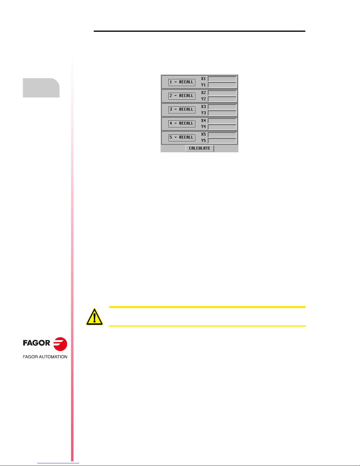
·64·
Operating manual
CNC 8055
CNC 8055i
2.
OPERATING IN JOG MODE
·MC· OPTION
SOFT: V02.2X
Tool calibration
Operation
After selecting the type of part to be centered (rectangular or circular) proceed as follows:
1. Move the tool until touching the desired point of the part.
2. Place the focus in the box of the type "1 - RECALL" corresponding to the desired point and press
[RECALL]. At this time, the coordinates of that point will be updated.
3. Repeat steps 1 and 2 for the rest of the points of the part.
4. After updating all the points, to calculate the center and the angle, place the focus on the
"CALCULATE" button and press [ENTER]. The angle is only calculated when the part is
rectangular and centering is done on both axes.
5. Once the whole process is finished, the CNC screen will show the center of the part and the
angle if it has been selected.
If coordinate preset is active and the new part zero changes, the CNC will request confirmation.
6. If the new coordinate preset has been applied and it is working in part coordinates, the
coordinates of the points will be updated with respect to the new reference point.
Arithmetic parameters modified by the cycle:
Once the part center and angle (only if necessary) have been calculated, the values obtained will
be saved in the following general arithmetic parameters:
P296 Angle between the part and the X axis ().
P298 Part center along the X axis (Xc).
P299 Part center along the Y axis (Yc).
In the ISO mode of the conversational mode, on the screen of the programming assistance for
pattern rotation, when pressing [RECALL] while the focus is in the field, this parameter will take
the value calculated in the manual part centering cycle.
If the last cycle executed at the CNC using global parameter P296 was not the manual centering cycle,
the
value will not be the one calculated in this cycle.
Page 65

Operating manual
CNC 8055
CNC 8055i
OPERATING IN JOG MODE
2.
·MC· OPTION
SOFT: V02.2X
·65·
Tool calibration
2.7.5 Tabletop probe calibration (level 4)
The new tabletop probe calibration cycle level 4 makes probe calibration easier. This reduces
machine preparation time.
The tool used for calibration must properly calibrated in radius and length.
Data to be entered
[ T ] Tool number
It defines the number of the tool used to calibrate the probe. If not programmed or programmed with
a 0 value, the CNC will display the corresponding error message.
[ D ] Tool offset number
It defines the tool offset number. If not programmed, it assumes the offset number assigned to T
in the tool table.
[ Ds ] Approach distance
Probe approaching distance in each probing movement. If not programmed or programmed with
a 0 value, the CNC will display the corresponding error message.
[ Dr ] Withdrawal distance
Distance the tool retracts after touching the probe to take the measurement. If not programmed or
programmed with a 0 value, the CNC will display the corresponding error message.
[ Fs ] Searching feedrate
Probe searching feedrate. If not programmed or programmed with a 0 value, the CNC will display
the corresponding error message.
[ F ] Measuring feedrate
Measuring feedrate. If not programmed or programmed with a 0 value, the CNC will display the
corresponding error message.
Type of calibration
Z
Y
X
Ds
Ds
It indicates whether the calibration is simple or double.
• Single calibration: the calibration is carried out in the 4 quadrants of the probe
with the spindle that holds the tool oriented at 0º.
• Double calibration: the calibration is carried out twice in the 4 quadrants of the
probe, one with the spindle positioned at 0º and the other with the spindle
positioned at 180º. This prevents tool eccentricity errors.
Page 66

·66·
Operating manual
CNC 8055
CNC 8055i
2.
OPERATING IN JOG MODE
·MC· OPTION
SOFT: V02.2X
Tool calibration
Programming method for probe coordinates
It indicates whether the cycle assumes the probe position defined in the machine parameters or the
position defined in the cycle. To select one of them, use the cursor to select the "Machine parameters
/ Programmable parameters" box and press the two-color key.
Machine parameters: The cycle assumes the probe position defined in the machine
parameters.
Programmed parameters: The cycle assumes the probe position defined in the cycle (Xmax,
Xmin, Ymax, Ymin, Zmax, Zmin).
[ Xmax ] Approximate X axis coordinate of the most positive side of the probe
Approximate coordinate of the most positive side of the probe, along the abscissa axis. If not
programmed, it will assume the value of general machine parameter PRBXMAX (P41).
[ Xmin ] Approximate X axis coordinate of the least positive side of the probe
Approximate coordinate of the least positive side of the probe, along the abscissa axis. If not
programmed, it will assume the value of general machine parameter PRBXMIN (P40).
[ Ymax ] Approximate Y axis coordinate of the most positive side of the probe
Approximate coordinate of the most positive side of the probe, along the ordinate axis. If not
programmed, it will assume the value of general machine parameter PRBYMAX (P43).
[ Ymin ] Approximate Y axis coordinate of the least positive side of the probe
Approximate coordinate of the least positive side of the probe, along the ordinate axis. If not
programmed, it will assume the value of general machine parameter PRBYMIN (P42).
[ Zmax ] Approximate Z axis coordinate of the most positive side of the probe
Approximate coordinate of the most positive side of the probe, along the Z axis. If not programmed,
it will assume the value of general machine parameter PRBZMAX (P45).
[ Zmin ] Approximate Z axis coordinate of the least positive side of the probe
Approximate coordinate of the least positive side of the probe, along the Z axis. If not programmed,
it will assume the value of general machine parameter PRBZMIN (P44).
Arithmetic parameters modified by the cycle
Once the cycle has been completed, the CNC will return the real values obtained after
measurement, in the following global arithmetic parameters.
P295 Real coordinate of the least positive side of the probe, along the abscissa axis.
P296 Real coordinate of the most positive side of the probe, along the abscissa axis.
P297 Real coordinate of the least positive side of the probe, along the ordinate axis.
P298 Real coordinate of the most positive side of the probe, along the ordinate axis.
P299 Real coordinate of the measured probe side along the longitudinal axis.
Page 67

Operating manual
CNC 8055
CNC 8055i
OPERATING IN JOG MODE
2.
·MC· OPTION
SOFT: V02.2X
·67·
Spindle control
2.8 Spindle control
The standard screen of the MC mode offers the following spindle data.
1. Real spindle speed in rpm.
2. Theoretical spindle speed in rpm.
To select another speed, press the [S] key. The CNC highlights the current value.
Enter the new value and press [START]. The CNC assumes that value and refreshes the real
spindle speed.
The maximum spindle speed is saved in the MDISL variable. This variable is updated (refreshed)
when programming function "G92 S" via ISO.
3. Percentage of the theoretical spindle speed being applied.
To modify the percentage (%), press the following keys.
4. Spindle status:
To modify the spindle status, press the following keys:
Spindle clockwise,
Spindle counterclockwise
Spindle stopped.
Page 68
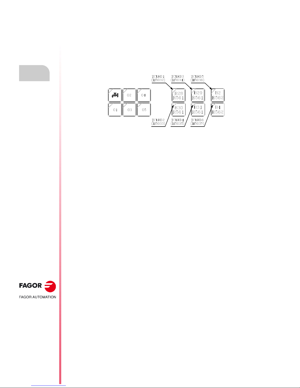
·68·
Operating manual
CNC 8055
CNC 8055i
2.
OPERATING IN JOG MODE
·MC· OPTION
SOFT: V02.2X
Controlling the external devices
2.9 Controlling the external devices
With this CNC, it is possible to activate and deactivate, via keyboard, up to 6 external devices, for
example, the coolant.
The machine manufacturer must use the PLC program to activate and deactivate the devices. The
CNC will inform the PLC about the status of each key. The corresponding register bit will be set to
1 when the key is pressed and 0 when it is not pressed.
The register bit for each key is:
The status of the lamp of each key must be controlled by the machine manufacturer through the
PLC program using the input variables TCLED* indicated in the figure.
Examples:
Coolant control:
DFU B28R561 = CPL TCLED1 = CPL O33
Tailstock control (O1). A number of conditions must be met for activating or deactivating the
tailstock, such as spindle stopped, etc.
DFU B30R561 AND (Rest of conditions) = CPL TCLED2 = CPL O34
Page 69

Operating manual
CNC 8055
CNC 8055i
OPERATING IN JOG MODE
2.
·MC· OPTION
SOFT: V02.2X
·69·
ISO management
2.10 ISO management
Access to the MDI mode or the ISO mode.
The ISO key may be used to access the MDI mode or the ISO mode.
To access the MDI mode, the CNC must be in jog mode and the ISO key must be pressed. The CNC
will show a window at the bottom of the standard (or special) screen.
In this window, it is possible to edit a block in ISO code and then execute it, like in MDI in M mode.
Displaying the last 10 MDI instructions.
From the MDI mode, pressing the [UP ARROW] or [DOWN ARROW] key opens a window that shows
the last 10 instructions that have been executed. This window resizes itself to fit the number of
instructions that have been saved.
To execute or modify an MDI line that has been executed earlier, proceed as follows:
• Go into MDI mode.
• Press the [UP ARROW] or [DOWN ARROW] key to open the window that shows the last MDI
instructions (up to 10).
• Use the [UP ARROW] or [DOWN ARROW] key to select the desired instruction.
Press [START] to execute the selected instruction.
Press [ENTER] to modify the selected instruction. Once the instruction has been modified,
press [START] to execute it.
Considerations.
• An MDI instruction is saved only if it is correct and if it is not the same as the previous one on
the list.
• The instructions are kept saved even after turning the unit off.
Generating an ISO-coded program
In the conversational mode of the CNC, it is possible to generate an ISO-coded program from an
operation (cycle) or on a part-program. See "6.5 Graphic representation" on page 154.
Page 70

·70·
Operating manual
CNC 8055
CNC 8055i
2.
OPERATING IN JOG MODE
·MC· OPTION
SOFT: V02.2X
ISO management
Page 71

CNC 8055
CNC 8055i
·MC· OPTION
SOFT: V02.2X
3
·71·
WORKING WITH OPERATIONS OR
CYCLES
Use the following CNC keys to select the different machining operations or cycles.
User cycles
The user cycle is edited like any other standard cycle of the MC mode. Once all the required data
has been defined, the user can simulate or execute the cycle like any other standard cycle of the
MC mode.
Cycles or operations of the CNC
When pressing any other key, the CNC selects the corresponding standard machining cycle,
changes the display and turns on the lamp of the key that has been pressed (indicating the selected
type.
Standard machining operations or cycles may be selected with each one of the following keys:
When pressing [PCALL], the CNC shows all the user cycles defined by the machine
manufacturer with the WGDRAW application.
Boring. Surface milling and slot milling.
Reaming. Pocket with profile (2D and 3D).
Tapping. Rectangular and circular boss.
Drilling and center punching. Rectangular and circular pocket.
Profile milling. Positioning.
When the machining operation or cycle has several levels, [LEVEL CYCLE] must be
pressed to select the desired cycle level.
Page 72
·72·
Operating manual
CNC 8055
CNC 8055i
3.
WORKING WITH OPERATIONS OR CYCLES
·MC· OPTION
SOFT: V02.2X
Some cycles may be carried out in the tool position or may be associated a multiple positioning so
the cycle may be repeated in several locations. The positioning moves may be selected with each
one of the following keys:
It is possible to combine ISO-coded blocks with standard and/or user cycles to create part-programs.
Chapter "5 Saving programs"describes in detail how to do it and how to use those programs.
To de-select a cycle and return to the standard screen, press the key for the selected cycle (the one
with the lamp on) or the [ESC] key.
Multiple positioning in several locations.
Multiple positioning in a straight line.
Multiple positioning in an arc.
Multiple positioning in a rectangular pattern.
Multiple positioning in a grid pattern.
When operating in conversational mode, do not use global parameters 150 through 299 (both
included), because the operations or cycles can modify these parameters and cause the machine to
malfunction.
Page 73

Operating manual
CNC 8055
CNC 8055i
WORKING WITH OPERATIONS OR CYCLES
3.
·MC· OPTION
SOFT: V02.2X
·73·
Operation editing mode
3.1 Operation editing mode
Once the operation has been selected, the CNC shows a screen like the following:
1. Name of the selected operation or work cycle.
2. Help graphics.
3. When it is a positioning operation, indicates its associated operation.
4. Current machine status. Coordinates and machining conditions.
5. Data defining the machining geometry.
6. Machining conditions for the operation.
The CNC will highlight an icon, a coordinate or one of the data defining the operation or cycle
indicating that it has been selected. Use the following keys to select another icon, data or coordinate.
The CNC selects the previous one or the next one.
The CNC selects the first coordinate for that axis. Pressing that key again selects
the next coordinate for that axis.
The CNC selects the corresponding roughing data. Pressing that key again selects
the corresponding finishing data.
The CNC selects the "S" roughing data. Pressing that key again selects the "S"
finishing data.
Page 74

·74·
Operating manual
CNC 8055
CNC 8055i
3.
WORKING WITH OPERATIONS OR CYCLES
·MC· OPTION
SOFT: V02.2X
Operation editing mode
3.1.1 Definition of machining conditions
Some operations keep the machining conditions throughout the execution (boring, reaming, etc.).
Other operations use some machining conditions for roughing and others for finishing (pockets,
bosses, etc.).
This section describes how to define all this data.
Selecting the roughing operation.
Place the cursor on the roughing checkbox, select or de-select the roughing operation pressing the
[TWO-COLOR] key and press [ENTER]. When de-selecting the roughing, all its data will stay in gray.
The data for finishing "side stock" and "depth stock" is turned on/off using the roughing checkbox
Selecting the finishing operation.
Place the cursor on the finishing checkbox, select or de-select the finishing operation pressing the
[TWO-COLOR] key and press [ENTER]. When de-selecting the finishing, all its data will stay in gray.
Axis feedrate (F).
Spindle turning speed (S).
Spindle turning direction
Machining tool (T).
Place the cursor over this data, key in the desired value and press [ENTER].
Press [ESC] to quit the tool calibration mode and return to the cycle
Coolant.
There are two ways to turn the coolant on or off.
Once the operation or the cycle is completed or the part-program it belongs to, the CNC outputs
the M9 function to the PLC.
Roughing pass ().
Finishing stocks (
,
z).
Place the cursor over this data, key in the desired value and press [ENTER].
Place the cursor over this data, key in the desired value and press [ENTER].
Place the cursor on this data and press the two-color key.
It is also possible to access the tool calibration mode to check or modify the data for the
selected tool. To do that, place the cursor on the "T" and press the key associated with
tool calibration.
Place the cursor on this data and press the two-color key to change the icon.
Turns the coolant on. The CNC outputs the M8 function to the PLC.
Turns the coolant off. The CNC outputs the M9 function to the PLC.
Place the cursor over this data, key in the desired value and press [ENTER].
Place the cursor over this data, key in the desired value and press [ENTER].
*
Page 75

Operating manual
CNC 8055
CNC 8055i
WORKING WITH OPERATIONS OR CYCLES
3.
·MC· OPTION
SOFT: V02.2X
·75·
Operation editing mode
3.1.2 Safety plane
There are four work planes in all operations:
• Starting plane or position occupied by the tool when calling the cycle. It is not defined; the CNC
sets it.
• Safety plane. It is used for the first approach and for withdrawing the tool after the machining
operation. It is set with parameter Zs.
• Part approaching plane. The CNC calculates it, at 1 mm from the part surface.
• Part surface. It is set with parameter Z.
The tool moves in rapid (G00) to the safety plane (Zs), moves on in rapid to the approach plane (up
to 1 mm off the part surface) and then moves at machining feedrate (G01) up to the part surface.
Approach to the part surface
The approach to the part surface depends on the current tool position.
• If it is above the safety plane (left figure), it first moves in X, Y and then in Z.
• If it is below the safety plane (right figure), it first moves in Z to the safety plane, then in X, Y and
finally in Z to the part surface.
Page 76

·76·
Operating manual
CNC 8055
CNC 8055i
3.
WORKING WITH OPERATIONS OR CYCLES
·MC· OPTION
SOFT: V02.2X
Operation editing mode
3.1.3 Cycle level
All the cycles have several editing levels. Each level has its own screen and the main window of the
cycle indicates, with tabs, the available levels and which one is selected.
To change levels, use the [LEVEL CYCLE] key or the [page up] and [page down] keys
to scroll up and down through the various levels.
Page 77

Operating manual
CNC 8055
CNC 8055i
WORKING WITH OPERATIONS OR CYCLES
3.
·MC· OPTION
SOFT: V02.2X
·77·
Simulating and executing the operation
3.2 Simulating and executing the operation
All the operations or cycles have 2 work modes; execution and editing.
• Press [ESC] to switch from editing mode to execution mode.
• Press [ESC] to switch from executing mode to editing mode.
For further information on simulating and executing cycles, see the chapter "6 Execution and
simulation".
The operation or cycle may be simulated in either mode. To do that, press the
[GRAPHICS] key.
To execute the operation or cycle, select the execution mode and press [START].
Editing mode Execution mode
Page 78

·78·
Operating manual
CNC 8055
CNC 8055i
3.
WORKING WITH OPERATIONS OR CYCLES
·MC· OPTION
SOFT: V02.2X
Simulating and executing the operation
3.2.1 Background cycle editing
It is possible to edit an operation or cycle while executing a program or part (background editing).
The new operation edited may be saved as part of a part-program other than the one being executed.
The operation being edited in background cannot be executed or simulated, and the current position
of the machine cannot be assigned to a coordinate.
Use the following keys to inspect or change a tool while editing in background.
Pressing the [T] key without quitting background editing selects the T field of the operation or of the
canned cycle being edited.
Interrupts the execution and goes on editing in background.
To quit background editing.
To access tool inspection.
Background editing is not possible while executing an independent operation or cycle. It can only be
done while executing a program or part.
i
Page 79

Operating manual
CNC 8055
CNC 8055i
WORKING WITH OPERATIONS OR CYCLES
3.
·MC· OPTION
SOFT: V02.2X
·79·
Profile milling operation
3.3 Profile milling operation
This cycle may be defined in two ways:
Level 1.
The following data must be defined:
• The starting point (X1, Y1), the intermediate points (P1 through P12), the last point (Xn, Yn) and
the machining conditions in Z (Zs, Z, P, I, Fz).
• Also, in the area for roughing operation data, it must be defined whether the milling operation
is carried out with or without tool compensation.
Level 2.
The following data must be defined:
• The starting point (X, Y), the "Profile program" number and the machining conditions in Z (Zs,
Z, P, I, Fz).
• Also, in the area for roughing operation data, it must be defined whether the milling operation
is carried out with or without tool compensation.
This key accesses the profile milling operation.
Page 80

·80·
Operating manual
CNC 8055
CNC 8055i
3.
WORKING WITH OPERATIONS OR CYCLES
·MC· OPTION
SOFT: V02.2X
Profile milling operation
3.3.1 Definition of data
Coordinates of the first and last points.
The coordinates are defined one by one. After placing the cursor on the coordinates of the axes to
be defined, the value is entered in one of the following ways.
• Entering the value manually. Key in the desired value and press [ENTER].
• Assign the current machine position.
Jog the axis with the handwheel or the JOG keys up to the desired point. Press [RECALL] so
the selected data assumes the value shown in the top right window and press [ENTER].
The top right window shows the tool position at all times.
Intermediate points (level 1).
The intermediate points are defined one by one. When not using the 12 definition points, the first
unused point must be defined with the same coordinates as the last point of the profile.
The following must be defined for each point.
If a coordinate is left blank, the cycle will assume that it is the same as that of the previous one.
The coordinates of each point may also be defined incrementally. To do that, select the desired
coordinate with the cursor and press the two-color key. Both coordinates of the selected point will
be shown preceded by the "" icon that indicates the incremental value with respect to the previous
point.
Deleting all the points of a profile.
Once all the desired points have been programmed, they may all be erased at once. To delete all
the programmed points at the same time, proceed as follows:
• Place the cursor on the text "DEF. PROFILE (max 12 points)" of the window where the points
are edited.
• In the instant the cursor is placed in this position, the text changes to: "CLEAR - Delete all the
points".
• At this moment, pressing [CLEAR] displays a window requesting confirmation to delete all the
points: Press the [ENTER] to delete all the points or [ESC] not to delete them.
• The X, Y coordinates are defined one by one like the coordinates of the first and last
points.
• Type of corner. To select the type of corner, place the cursor over this icon and press
the two-color key.
If defined... The CNC assumes...
X1 25.323 Y1 26.557 Point: X1 25.323 Y1 26.557
X2 Y2 78.998 Point: X2 25.323 Y2 78.998
X3 67.441 Y3 83.231 Point: X3 67.441 Y3 83.231
X4 Y4 Point: X4 67.441 Y4 83.231
X5 Y5 There are no more points, it is a repetition of the previous
point.
Page 81

Operating manual
CNC 8055
CNC 8055i
WORKING WITH OPERATIONS OR CYCLES
3.
·MC· OPTION
SOFT: V02.2X
·81·
Profile milling operation
Machining conditions in Z (Zs, Z, P, I, Fz).
The machining conditions are defined one by one.
• The Zs and Z values are defined as the coordinates of the first and last points.
• To define the rest of the values (P, I, Fz), go to the corresponding window, key in the desired value
and press [ENTER].
If the penetration step is programmed with a positive sign (I+), the cycle recalculates the step
so all the penetrations are identical, this being equal to or less than the one programmed. If
programmed with a negative sign (I-), the cycle is machined with the given pass (step) except
the last pass that machines the rest.
Milling with or without tool radius compensation.
To select the type of corner, place the cursor over this icon and press the two-color key.
Without tool radius Compensation.
With left-hand tool radius compensation.
With right-hand tool radius compensation.
Page 82

·82·
Operating manual
CNC 8055
CNC 8055i
3.
WORKING WITH OPERATIONS OR CYCLES
·MC· OPTION
SOFT: V02.2X
Profile milling operation
3.3.2 Profile definition (level 2)
Defining the profile program.
The profile program may be defined as follows.
• Key in the profile program number directly.
If the "profile program" is known, key in the program number and press [ENTER].
• Access the "profile programs" to select one of them.
Press the [] key. The canned cycle will show a window with the profile programs currently
defined. Use the [] and [] keys to move around this window. After positioning the cursor on
the desired program, press [ENTER].
To exit this window without selecting any program, use the [] y [] keys.
Editing a new profile program.
To edit a new profile program, key in the program number (between 0 and 999) and press [RECALL].
The CNC will show the window for the profile editor (see operating manual).
After editing the profile, the CNC requests the comment to be associated with the "Profile program"
that has been edited. Enter the desired comment and press [ENTER]. If no comment is desired,
press [ESC].
Copying a profile program.
Press the [] key. The canned cycle will show the profile programs currently defined. Place the
cursor on the profile program to be copied and press [P.PROG]. The CNC requests the number of
the new profile and it allows changing its comment. If the number entered is the same as that of
an existing profile, the CNC requests confirmation to replace it.
Modify an already existing "Profile program".
To modify a profile program, key in the program number and press [RECALL]. The CNC will show,
in the window for the profile editor, the profile that is currently defined.
With this profile, the following actions are possible:
• Add new items at the end of the present profile.
• Modifying the data of any element.
• Modify or include chamfers, rounded corners, etc.
• Deleting elements of the profile.
Deleting an existing profile program.
Press the [] key. The canned cycle will show the profile programs currently defined. Place the
cursor on the profile program to be deleted and press [CLEAR]. The CNC requests confirmation.
The profile programs can also be accessed in the "M" mode because the CNC saves them internally
as P997xxx.
Example: Profile program 123 is internally saved as P997123.
When saving a part-program that contains a level-2 profile cycle into an external device, PC, floppy
drive, etc. also save its associated profile program P997xxx.
i
Page 83

Operating manual
CNC 8055
CNC 8055i
WORKING WITH OPERATIONS OR CYCLES
3.
·MC· OPTION
SOFT: V02.2X
·83·
Surface milling and slot milling operations
3.4 Surface milling and slot milling operations
Surface milling operation.
The following data must be defined:
• The type of surface milling, the starting point (X1, Y1), the dimensions of the surface milling (L,
H, E,) and the machining conditions in Z (Zs, Z, P, I, Fz).
• Also, you must define the milling pass () in the data area for the roughing operation and the
finishing stock (z) in the data area for the finishing operation.
Grooving operation.
The following data must be defined:
• The type of slot milling, the starting point (X1, Y1), the dimensions of the slot (L, H, E, ) and
the machining conditions in Z (Zs, Z, P, I, Fz).
This key accesses the surface milling and slot milling operations.
• In the roughing area, define the milling pass () and the machining direction.
• In the finishing area, define the finishing stocks ( and z), the number of finishing
passes and the machining direction.
Page 84

·84·
Operating manual
CNC 8055
CNC 8055i
3.
WORKING WITH OPERATIONS OR CYCLES
·MC· OPTION
SOFT: V02.2X
Surface milling and slot milling operations
3.4.1 Defining the surface milling data
Type of surface milling.
Coordinates of starting point (X1, Y1).
Define one of the corners of the surface to be milled (X1, Y1). The coordinates are defined one by
one. After placing the cursor on the coordinates of the axes to be defined, the value is entered in
one of the following ways.
• Entering the value manually. Key in the desired value and press [ENTER].
• Assign the current machine position.
Jog the axis with the handwheel or the JOG keys up to the desired point. Press [RECALL] so
the selected data assumes the value shown in the top right window and press [ENTER].
The top right window shows the tool position at all times.
Surface to be milled (L, H, E, ).
After defining one of the corners (X1, Y1), define the length (L) and width (H) of the surface to be
milled. The sign of the L and H indicates the orientation referred to the X1, Y1 point.
Once the surface to be milled has been defined, the icon shown at the bottom right (roughing and
finishing area) may be used to select the corner to start milling the surface.
• The data E and are defined one by one. Place the cursor in the corresponding window, key
in the desired value and press [ENTER].
When programming parameter "E" with a value smaller than the tool radius, the CNC executes
the surface milling with an "E" value equal to the tool radius.
Machining conditions in Z (Zs, Z, P, I, Fz).
The machining conditions are defined one by one.
• The Zs and Z values are defined as the coordinates of the first and last points.
• To define the rest of the values (P, I, Fz), go to the corresponding window, key in the desired value
and press [ENTER].
If the penetration step is programmed with a positive sign (I+), the cycle recalculates the step
so all the penetrations are identical, this being equal to or less than the one programmed. If
programmed with a negative sign (I-), the cycle is machined with the given pass (step) except
the last pass that machines the rest.
Milling pass () and finishing stock (z).
These data are defined one by one. Place the cursor in the corresponding window, key in the desired
value and press [ENTER].
Type of surface milling.
To select the type of surface milling, place the cursor over this icon and press the twocolor key.
Page 85

Operating manual
CNC 8055
CNC 8055i
WORKING WITH OPERATIONS OR CYCLES
3.
·MC· OPTION
SOFT: V02.2X
·85·
Surface milling and slot milling operations
3.4.2 Defining the grooving data
Type of grooving.
Coordinates of the starting point.
The coordinates are defined one by one. After placing the cursor on the coordinates of the axes to
be defined, the value is entered in one of the following ways.
• Entering the value manually. Key in the desired value and press [ENTER].
• Assign the current machine position.
Jog the axis with the handwheel or the JOG keys up to the desired point. Press [RECALL] so
the selected data assumes the value shown in the top right window and press [ENTER].
The top right window shows the tool position at all times.
Dimensions of the slot (L, H, E, ).
These data are defined one by one. Place the cursor in the corresponding window, key in the desired
value and press [ENTER].
When programming parameter "E" with a value smaller than the tool radius, the CNC executes the
slot milling with an "E" value equal to the tool radius.
Machining conditions in Z (Zs, Z, P, I, Fz).
The machining conditions are defined one by one.
• The Zs and Z values are defined as the coordinates of the first and last points.
• To define the rest of the values (P, I, Fz), go to the corresponding window, key in the desired value
and press [ENTER].
If the penetration step is programmed with a positive sign (I+), the cycle recalculates the step
so all the penetrations are identical, this being equal to or less than the one programmed. If
programmed with a negative sign (I-), the cycle is machined with the given pass (step) except
the last pass that machines the rest.
Milling pass () and finishing stock (z).
These data are defined one by one. Place the cursor in the corresponding window, key in the desired
value and press [ENTER].
Type of grooving.
To select the type of grooving, place the cursor over this icon and press the two-color key.
Page 86

·86·
Operating manual
CNC 8055
CNC 8055i
3.
WORKING WITH OPERATIONS OR CYCLES
·MC· OPTION
SOFT: V02.2X
Surface milling and slot milling operations
Clockwise milling of the different types of slots .
Page 87

Operating manual
CNC 8055
CNC 8055i
WORKING WITH OPERATIONS OR CYCLES
3.
·MC· OPTION
SOFT: V02.2X
·87·
Pocket cycle with a profile
3.5 Pocket cycle with a profile
A pocket is composed by an external contour or profile (1) and a series of internal contours or profiles
(2). These internal profiles are called islands.
• In 2D pockets (top left figure), all the walls of the outside profile and of the islands are vertical.
• In 3D pockets (top right figure), one, several or all the walls of the outside pocket and/or of the
islands are not vertical (up to a maximum of 4).
Programming 2D pockets with profile.
When defining the profile, one must indicate, besides the outside contour of the pocket, the contour
or contours of the islands.
The machining in Z is defined with the following parameters:
Zs Safety plane coordinate.
Z Part surface coordinate.
P Pocket depth.
I Step in Z.
Fz Penetrating feedrate in Z.
The following must be defined in the data area for the roughing operation:
The sideways penetration angle.
The milling pass.
The following must be defined in the data area for the finishing operation:
The sideways penetration angle.
Finishing stock on the side walls.
z Finishing stock at the bottom.
N Number of finishing passes in Z.
This key accesses the pocket-with-profile operation.
There are two types of pocket with profile; 2D and 3D.
Pocket with 2D profile Pocket with 2D profile
Page 88

·88·
Operating manual
CNC 8055
CNC 8055i
3.
WORKING WITH OPERATIONS OR CYCLES
·MC· OPTION
SOFT: V02.2X
Pocket cycle with a profile
Programming 3D pockets with profile.
Pocket identification number (POCK. 3D).
Several 3D pockets are possible. The CNC associates to each 3D pocket all its data (surface
profile, depth profile, machining conditions, etc.).
Surface profile or profile in the XY plane. Profile (P. XY).
One must indicate, besides the outside contour of the pocket, the contour or contours of the
possible islands.
Depth profile for the first profile defined. Profile (P. Z1).
They usually correspond to the outside contour of the pocket.
Depth profile for the second profile defined. Profile (P. Z2).
They usually correspond to the contour of the first island defined.
Depth profile for the third profile defined. Profile (P. Z3).
They usually correspond to the contour of the second island defined.
Depth profile for the fourth profile defined. Profile (P. Z4).
They usually correspond to the contour of the third island defined.
The machining in Z is defined with the following parameters:
Zs Safety plane coordinate.
Z Part surface coordinate.
P Pocket depth.
I1 Roughing step in Z.
Fz Penetrating feedrate in Z.
I2 Semi-finishing step in Z.
The following must be defined in the data area for the roughing operation:
The sideways penetration angle.
The milling pass.
The following must be defined in the data area for the finishing operation:
R Tool tip radius.
Finishing stock on the side walls.
Finishing pass.
Once all the profiles have been defined, the configuration of the 3D pocket must
be validated. To do that, place the cursor on the icon (a) and press [ENTER] to
validate the pocket. The cycle will show the icon (b).
Direction of the finishing passes on the walls.
(a) (b)
The pocket configuration program and the profile programs can also be accessed in the "M" mode
because the CNC saves them internally as:
P995xxx - 3D pocket configuration.
P998xxx - The profiles of the XY plane, both in 2D and 3D pockets.
P996xxx - The depth profiles of the 3D pockets.
i
Page 89

Operating manual
CNC 8055
CNC 8055i
WORKING WITH OPERATIONS OR CYCLES
3.
·MC· OPTION
SOFT: V02.2X
·89·
Pocket cycle with a profile
3.5.1 Definition of data
Machining conditions in Z (Zs, Z).
To define the values (Zs and Z), after going to the corresponding window, the value is entered in
one of the following ways.
• Entering the value manually. Key in the desired value and press [ENTER].
• Assign the current machine position.
Jog the axis with the handwheel or the JOG keys up to the desired point. Press [RECALL] so
the selected data assumes the value shown in the top right window and press [ENTER].
The top right window shows the tool position at all times.
Machining conditions in Z (P, Fz, I, I1, I2).
The machining conditions are defined one by one.
• To define the values (P, Fz, I, I1, I2), go to the corresponding window, key in the desired value
and press [ENTER].
If the penetration step is programmed with a positive sign (I+), the cycle recalculates the step
so all the penetrations are identical, this being equal to or less than the one programmed. If
programmed with a negative sign (I-), the cycle is machined with the given pass (step) except
the last pass that machines the rest.
Milling pass () and finishing pass ().
Place the cursor in the corresponding window, roughing or finishing operation, key in the desired
value and press [ENTER].
Sideways penetration angle (, ).
Place the cursor in the corresponding window, roughing or finishing operation, key in the desired
value and press [ENTER].
Finishing stock on the side walls () and at the bottom (z).
Place the cursor in the corresponding window, finishing operation, key in the desired value and press
[ENTER].
Finishing tool tip radius (R).
Place the cursor in the corresponding window, finishing operation, key in the desired value and press
[ENTER].
Direction of the finishing passes on the walls.
To select the direction of the finishing passes on the walls, place the cursor
over this icon and press the two-color key.
Page 90

·90·
Operating manual
CNC 8055
CNC 8055i
3.
WORKING WITH OPERATIONS OR CYCLES
·MC· OPTION
SOFT: V02.2X
Pocket cycle with a profile
3.5.2 Profile definition
Defining the profile program.
The profile program may be defined as follows.
• Key in the profile program number directly.
If the "profile program" is known, key in the program number and press [ENTER].
• Access the "profile programs" to select one of them.
Press the [] key. The canned cycle will show a window with the profile programs currently
defined. There are 3 different directories, one for the pocket configuration profiles, another one
for the profiles in the XY plane and another one for the depth profiles Use the [] and [] keys
to move around this window. After positioning the cursor on the desired program, press [ENTER].
To exit this window without selecting any program, use the [] y [] keys.
Editing a new profile program.
To edit a new profile program, key in the program number (between 0 and 999) and press [RECALL].
The CNC will show the window for the profile editor (see operating manual).
After editing the profile, the CNC requests the comment to be associated with the "Profile program"
that has been edited. Enter the desired comment and press [ENTER]. If no comment is desired,
press [ESC].
Copying a profile program.
Press the [] key. The canned cycle will show the profile programs currently defined. Place the
cursor on the profile program to be copied and press [P.PROG]. The CNC requests the number of
the new profile and it allows changing its comment. If the number entered is the same as that of
an existing profile, the CNC requests confirmation to replace it.
Modify an already existing "Profile program".
To modify a profile program, key in the program number and press [RECALL]. The CNC will show,
in the window for the profile editor, the profile that is currently defined.
With this profile, the following actions are possible:
• Add new items at the end of the present profile.
• Modifying the data of any element.
• Modify or include chamfers, rounded corners, etc.
• Deleting elements of the profile.
Deleting an existing profile program.
Press the [] key. The canned cycle will show the profile programs currently defined. Place the
cursor on the profile program to be deleted and press [CLEAR]. The CNC requests confirmation.
The profile programs can also be accessed in the "M" mode because the CNC saves them internally as:
P995xxx - 3D pocket configuration.
P998xxx - The profiles of the XY plane, both in 2D and 3D pockets.
P996xxx - The depth profiles of the 3D pockets.
When saving a part-program that contains a pocket-with-profile cycle into an external device, PC,
floppy drive, etc. also save its associated profile programs.
i
Page 91

Operating manual
CNC 8055
CNC 8055i
WORKING WITH OPERATIONS OR CYCLES
3.
·MC· OPTION
SOFT: V02.2X
·91·
Pocket cycle with a profile
3.5.3 Profile definition examples
Example of how to define a 2D profile without islands:
2D pocket.
Configuration.
Profile.
Corners.
End.
Save profile.
Profile 1 [RECALL]
Abscissa axis: X Ordinate axis: Y
Autozoom: Yes Validate
Initial point X 20 Y -8 Validate
Straight line X 20 Y -40 Validate
Straight line X 145 Y -40 Validate
Straight line X 145 Y -25 Validate
Clockwise arc Xf 145 Yf 25 R 25 Validate
Straight line X 145 Y 40 Validate
Straight line X 20 Y 40 Validate
Straight line X 20 Y 8 Validate
Straight line X 55 Y 8 Validate
Straight line X 55 Y -8 Validate
Straight line X 20 Y -8 Validate
Lower left corner [ENTER] Chamfer 15 [ENTER]
Upper left corner [ENTER] Chamfer 15 [ENTER]
[ESC]
Page 92

·92·
Operating manual
CNC 8055
CNC 8055i
3.
WORKING WITH OPERATIONS OR CYCLES
·MC· OPTION
SOFT: V02.2X
Pocket cycle with a profile
Example of how to define a 2D profile with islands:
2D pocket.
Configuration.
Profile (outside profile).
Corners.
New profile (island).
End.
Save profile.
Profile 2 [RECALL]
Abscissa axis: X Ordinate axis: Y
Autozoom: Yes Validate
Initial point X 20 Y 0 Validate
Straight line X 20 Y -40 Validate
Straight line X 145 Y -40 Validate
Straight line X 145 Y 40 Validate
Straight line X 20 Y 40 Validate
Straight line X 20 Y 0 Validate
Lower left corner [ENTER] Chamfer 15 [ENTER]
Lower right corner [ENTER] Chamfer 15 [ENTER]
Upper right corner [ENTER] Chamfer 15 [ENTER]
Upper left corner [ENTER] Chamfer 15 [ENTER]
[ESC]
Profile
Initial point X 115 Y -25 Validate
Straight line X 115 Y 0 Validate
Clockwise arc Xf 90 Yf 25 Xc 115 Yc 25 R 25 Validate
Straight line X 50 Y 25 Validate
Straight line X 50 Y 0 Validate
Clockwise arc Xf 75 Yf -25 Xc 50 Yc -25 R 25 Validate
Straight line X 115 Y -25 Validate
Page 93

Operating manual
CNC 8055
CNC 8055i
WORKING WITH OPERATIONS OR CYCLES
3.
·MC· OPTION
SOFT: V02.2X
·93·
Pocket cycle with a profile
Example of how to define a 3D profile without islands:
3D pocket = 1
Outside profile (P.XY).
Configuration.
Profile.
End.
Save profile.
Depth profile (P.Z1).
Configuration.
Profile.
End.
Save profile.
P.XY= 3 [RECALL]
Abscissa axis: X Ordinate axis: Y
Autozoom: Yes Validate
Initial point X 20 Y 0 Validate
Straight line X 20 Y -40 Validate
Straight line X 145 Y -40 Validate
Straight line X 145 Y 40 Validate
Straight line X 20 Y 40 Validate
Straight line X 20 Y 0 Validate
P.XY= 3 [RECALL]
Abscissa axis: X Ordinate axis: Z
Autozoom: Yes Validate
Initial point X 20 Z 0 Validate
Straight line X 30 Z -20 Validate
Page 94

·94·
Operating manual
CNC 8055
CNC 8055i
3.
WORKING WITH OPERATIONS OR CYCLES
·MC· OPTION
SOFT: V02.2X
Pocket cycle with a profile
Example of how to define a 3D profile with islands:
3D pocket = 2
Outside profile (P.XY).
Configuration.
Profile (pocket profile).
Profile (island profile).
End.
Save profile.
P.XY= 4 [RECALL]
Abscissa axis: X Ordinate axis: Y
Autozoom: Yes Validate
Initial point X 20 Y 0 Validate
Straight line X 20 Y -40 Validate
Straight line X 145 Y -40 Validate
Straight line X 145 Y 40 Validate
Straight line X 20 Y 40 Validate
Straight line X 20 Y 0 Validate
Circle X 62.5 Y0 Xc 82.5 Yc 0 Validate
Page 95

Operating manual
CNC 8055
CNC 8055i
WORKING WITH OPERATIONS OR CYCLES
3.
·MC· OPTION
SOFT: V02.2X
·95·
Pocket cycle with a profile
Depth profile (P.Z1).
Configuration.
Profile (pocket depth profile).
End.
Save profile.
Depth profile (P.Z2).
Configuration.
Profile (island depth profile).
End.
Save profile.
P. Z 1 = 2 [RECALL]
Abscissa axis: X Ordinate axis: Z
Autozoom: Yes Validate
Initial point X 20 Z 0 Validate
Straight line X 30 Z -20 Validate
P. Z 1 = 3 [RECALL]
Abscissa axis: X Ordinate axis: Z
Autozoom: Yes Validate
Initial point X 77.5 Z 0 Validate
Straight line X 62.5 Z -20 Validate
Page 96

·96·
Operating manual
CNC 8055
CNC 8055i
3.
WORKING WITH OPERATIONS OR CYCLES
·MC· OPTION
SOFT: V02.2X
Rectangular and circular boss cycles
3.6 Rectangular and circular boss cycles
Rectangular boss cycle.
The following data must be defined:
• The starting point (X1, Y1), the dimensions of the boss (L, H), the inclination angle (), the
amount of stock to be removed (Q), the type of corner and the machining conditions in Z (Zs,
Z, P, I, Fz).
Circular boss cycle.
The following data must be defined:
• The center coordinates, (Xc, Yc), the radius of the boss (R), the amount of stock to be removed
(Q) and the machining conditions in Z (Zs, Z, P, I, Fz).
This key accesses the circular boss and rectangular boss operations.
• In the roughing area, define the milling pass () and the machining direction.
• In the finishing area, define the finishing stocks ( and z), the number of finishing
passes and the machining direction.
• In the roughing area, define the milling pass () and the machining direction.
• In the finishing area, define the finishing stocks ( and z), the number of finishing
passes and the machining direction.
Page 97

Operating manual
CNC 8055
CNC 8055i
WORKING WITH OPERATIONS OR CYCLES
3.
·MC· OPTION
SOFT: V02.2X
·97·
Rectangular and circular boss cycles
3.6.1 Definition of data
Rectangular boss. Position of the starting point.
When associating multiple machining to a cycle, this point indicates the position where those
machining operations are applied. See "3.13 Multiple positioning" on page 118.
Coordinates of the starting point.
The coordinates are defined one by one. After placing the cursor on the coordinates of the axes to
be defined, the value is entered in one of the following ways.
• Entering the value manually. Key in the desired value and press [ENTER].
• Assign the current machine position.
Jog the axis with the handwheel or the JOG keys up to the desired point. Press [RECALL] so
the selected data assumes the value shown in the top right window and press [ENTER].
The top right window shows the tool position at all times.
Rectangular boss: Dimensions, inclination angle and stock to be removed.
These data are defined one by one. Place the cursor in the corresponding window, key in the desired
value and press [ENTER].
Type of corner.
Circular boss: Center coordinates, radius and stock to be removed.
These data are defined one by one.
• The center coordinates (Xc, Yc) are defined as the coordinates of the first and last points.
• To define the rest of the values (R, Q), go to the corresponding window, key in the desired value
and press [ENTER].
Machining conditions in Z (Zs, Z, P, I, Fz).
The machining conditions are defined one by one.
• The Zs and Z values are defined as the coordinates of the first and last points.
• To define the rest of the values (P, I, Fz), go to the corresponding window, key in the desired value
and press [ENTER].
If the penetration step is programmed with a positive sign (I+), the cycle recalculates the step
so all the penetrations are identical, this being equal to or less than the one programmed. If
programmed with a negative sign (I-), the cycle is machined with the given pass (step) except
the last pass that machines the rest.
The starting point of the boss may be located at a vertex or in the center. To select its
position, place the cursor over this icon and press the two-color key.
Type of corner.
To select the type of corner, place the cursor over this icon and press the two-color key.
(X,Y)
(X,Y)
Page 98

·98·
Operating manual
CNC 8055
CNC 8055i
3.
WORKING WITH OPERATIONS OR CYCLES
·MC· OPTION
SOFT: V02.2X
Rectangular and circular boss cycles
Milling pass (). Finishing stock on the side walls () and at the bottom (z). Number
of finishing passes (N).
Place the cursor in the window for the finishing operation, key in the desired value and press
[ENTER].
Page 99

Operating manual
CNC 8055
CNC 8055i
WORKING WITH OPERATIONS OR CYCLES
3.
·MC· OPTION
SOFT: V02.2X
·99·
Rectangular and circular pocket cycles
3.7 Rectangular and circular pocket cycles
Rectangular pocket cycle (level 1).
The following data must be defined:
• The starting point (X, Y), the pocket dimensions (L, H) and the machining conditions in Z (Zs,
Z, P, I, Fz).
Rectangular pocket cycle (level 2).
The following data must be defined:
• The starting point (X, Y), the pocket dimensions (L, H), the inclination angle (), the type of corner
and the machining conditions in Z (Zs, Z, P, I, Fz).
This key accesses the circular pocket and rectangular pocket operations.
• Also, one must define the milling pass (, the finishing stock () and the machining
direction.
• In the roughing area, one must define the sideways penetration angle (), the milling
pass () and the machining direction.
• In the finishing area, one must define the sideways penetration angle (), the finishing
stocks ( and z), the number of finishing passes (N) and the machining direction.
Page 100

·100·
Operating manual
CNC 8055
CNC 8055i
3.
WORKING WITH OPERATIONS OR CYCLES
·MC· OPTION
SOFT: V02.2X
Rectangular and circular pocket cycles
Circular pocket cycle (level 1).
The following data must be defined:
• The center coordinates (Xc, Yc), the pocket radius (R) and the machining conditions in Z (Zs,
Z, P, I, Fz).
Circular pocket cycle (level 2).
This level is the right one to machine pre-emptied pockets or crowns.
The following data must be defined:
• The center coordinates (Xc, Yc), the inside radius (Ri) and the outside radius (Re) of the pocket
and the machining conditions in Z (Zs, Z, P, I, Fz).
• In the roughing area, one must define the sideways penetration angle (), the milling
pass () and the machining direction.
• In the finishing area, one must define the sideways penetration angle (), the finishing
stocks ( and z), the number of finishing passes (N) and the machining direction.
• In the roughing area, one must define the sideways penetration angle (), the milling
pass () and the machining direction.
• In the finishing area, one must define the sideways penetration angle (), the finishing
stocks ( and z), the number of finishing passes (N) and the machining direction.
 Loading...