

Page 1

CNC
8070
Programming manual
(Ref. 1309)
Page 2

MACHINE SAFETY
It is up to the machine manufacturer to make sure that the safety of the machine
is enabled in order to prevent personal injury and damage to the CNC or to the
products connected to it. On start-up and while validating CNC parameters, it
checks the status of the following safety elements. If any of them is disabled, the
CNC shows a warning message.
• Feedback alarm for analog axes.
• Software limits for analog and sercos linear axes.
• Following error monitoring for analog and sercos axes (except the spindle)
both at the CNC and at the drives.
• Tendency test on analog axes.
FAGOR AUTOMATION shall not be held responsible for any personal injuries or
physical damage caused or suffered by the CNC resulting from any of the safety
elements being disabled.
HARDWARE EXPANSIONS
FAGOR AUTOMATION shall not be held responsible for any personal injuries or
physical damage caused or suffered by the CNC resulting from any hardware
manipulation by personnel unauthorized by Fagor Automation.
If the CNC hardware is modified by personnel unauthorized by Fagor Automation,
it will no longer be under warranty.
COMPUTER VIRUSES
FAGOR AUTOMATION guarantees that the software installed contains no
computer viruses. It is up to the user to keep the unit virus free in order to
guarantee its proper operation.
Computer viruses at the CNC may cause it to malfunction. An antivirus software
is highly recommended if the CNC is connected directly to another PC, it is part
of a computer network or floppy disks or other computer media is used to transmit
data.
FAGOR AUTOMATION shall not be held responsible for any personal injuries or
physical damage caused or suffered by the CNC due a computer virus in the
system.
If a computer virus is found in the system, the unit will no longer be under warranty.
All rights reserved. No part of this documentation may be transmitted,
transcribed, stored in a backup device or translated into another language
without Fagor Automation’s consent. Unauthorized copying or distributing of this
software is prohibited.
The information described in this manual may be changed due to technical
modifications. Fagor Automation reserves the right to make any changes to the
contents of this manual without prior notice.
All the trade marks appearing in the manual belong to the corresponding owners.
The use of these marks by third parties for their own purpose could violate the
rights of the owners.
It is possible that CNC can execute more functions than those described in its
associated documentation; however, Fagor Automation does not guarantee the
validity of those applications. Therefore, except under the express permission
from Fagor Automation, any CNC application that is not described in the
documentation must be considered as "impossible". In any case, Fagor
Automation shall not be held responsible for any personal injuries or physical
damage caused or suffered by the CNC if it is used in any way other than as
explained in the related documentation.
The content of this manual and its validity for the product described here has been
verified. Even so, involuntary errors are possible, thus no absolute match is
guaranteed. Anyway, the contents of the manual is periodically checked making
and including the necessary corrections in a future edition. We appreciate your
suggestions for improvement.
The examples described in this manual are for learning purposes. Before using
them in industrial applications, they must be properly adapted making sure that
the safety regulations are fully met.
Page 3

Programming manual
INDEX
About the product ......................................................................................................................... 9
Declaration of conformity............................................................................................................ 11
Version history............................................................................................................................ 13
Safety conditions ........................................................................................................................ 23
Warranty terms ........................................................................................................................... 27
Material returning terms.............................................................................................................. 29
CNC maintenance ...................................................................................................................... 31
CHAPTER 1 CREATING A PROGRAM.
1.1 Programming languages................................................................................................ 33
1.2 Program structure. ......................................................................................................... 34
1.2.1 Program body............................................................................................................. 35
1.2.2 The subroutines. ........................................................................................................ 36
1.3 Program block structure................................................................................................. 37
1.3.1 Programming in ISO code.......................................................................................... 38
1.3.2 High-level language programming. ............................................................................ 40
1.4 Programming of the axes............................................................................................... 41
1.5 List of "G" functions........................................................................................................42
1.6 List of auxiliary (miscellaneous) M functions.................................................................. 46
1.7 List of statements and instructions................................................................................. 47
1.8 Comment programming. ................................................................................................ 50
1.9 Variables and constants................................................................................................. 51
1.10 Arithmetic parameters.................................................................................................... 52
1.11 Arithmetic and logic operators and functions. ................................................................ 53
1.12 Arithmetic and logic expressions. .................................................................................. 55
CHAPTER 2 MACHINE OVERVIEW
2.1 Axis nomenclature ......................................................................................................... 57
2.2 Coordinate system ......................................................................................................... 59
2.3 Reference systems ........................................................................................................ 60
2.3.1 Origins of the reference systems ............................................................................... 61
2.4 Home search..................................................................................................................62
2.4.1 Definition of "Home search" ....................................................................................... 62
2.4.2 "Home search" programming ..................................................................................... 63
CHAPTER 3 COORDINATE SYSTEM
3.1 Programming in millimeters (G71) or in inches (G70).................................................... 65
3.2 Absolute (G90) or incremental (G91) coordinates ......................................................... 66
3.2.1 Rotary axes................................................................................................................67
3.3 Programming in radius (G152) or in diameters (G151).................................................. 69
3.4 Coordinate programming ............................................................................................... 70
3.4.1 Cartesian coordinates ................................................................................................ 70
3.4.2 Polar coordinates ....................................................................................................... 71
CHAPTER 4 WORK PLANES.
4.1 About work planes on lathe and mill models.................................................................. 74
4.2 Select the main new work planes. ................................................................................. 75
4.2.1 Mill model or lathe model with "trihedron" type axis configuration. ............................ 75
4.2.2 Lathe model with "plane" type axis configuration....................................................... 76
4.3 Select any work plane and longitudinal axis. ................................................................. 77
4.4 Select the longitudinal axis of the tool............................................................................ 79
CNC 8070
CHAPTER 5 ORIGIN SELECTION
5.1 Programming with respect to machine zero................................................................... 82
5.2 Set the machine coordinate (G174). ............................................................................. 84
5.3 Fixture offset .................................................................................................................. 85
5.4 Coordinate preset (G92) ................................................................................................ 86
(REF. 1309)
·3·
Page 4

5.5 Zero offsets (G54-G59/G159)........................................................................................ 87
5.5.1 Variables for setting zero offsets................................................................................ 89
5.5.2 Incremental zero offset (G158) .................................................................................. 90
5.5.3 Excluding axes in the zero offset (G157) ................................................................... 92
5.6 Zero offset cancellation (G53) ....................................................................................... 93
5.7 Polar origin preset (G30) ............................................................................................... 94
CHAPTER 6 TECHNOLOGICAL FUNCTIONS
6.1 Machining feedrate (F)................................................................................................... 97
6.2 Feedrate related functions ............................................................................................. 99
6.2.1 Feedrate programming units (G93/G94/G95) ............................................................ 99
6.2.2 Feedrate blend (G108/G109/G193) ......................................................................... 100
6.2.3 Constant feedrate mode (G197/G196) .................................................................... 102
6.2.4 Cancellation of the % of feedrate override (G266)................................................... 104
6.2.5 Acceleration control (G130/G131) ........................................................................... 105
6.2.6 Jerk control (G132/G133) ........................................................................................ 107
6.2.7 Feed-Forward control (G134) .................................................................................. 108
6.2.8 AC-Forward control (G135)...................................................................................... 109
6.3 Spindle speed (S) ........................................................................................................ 110
6.4 Tool number (T) ........................................................................................................... 111
6.5 Tool offset number (D)................................................................................................. 114
6.6 Auxiliary (miscellaneous) functions (M) ....................................................................... 116
6.6.1 List of "M" functions ................................................................................................. 117
6.7 Auxiliary functions (H).................................................................................................. 118
CHAPTER 7 THE SPINDLE. BASIC CONTROL.
Programming manual
CNC 8070
7.1 The master spindle of the channel............................................................................... 120
7.1.1 Manual selection of a master spindle....................................................................... 122
7.2 Spindle speed .............................................................................................................. 123
7.2.1 G192. Turning speed limit........................................................................................ 124
7.2.2 Constant surface speed ........................................................................................... 125
7.3 Spindle start and stop .................................................................................................. 126
7.4 Gear change. ............................................................................................................... 128
7.5 Spindle orientation. ...................................................................................................... 130
7.5.1 The turning direction for spindle orientation............................................................. 132
7.5.2 M19 function with an associated subroutine. ........................................................... 134
7.5.3 Positioning speed..................................................................................................... 135
7.6 M functions with an associated subroutine. ................................................................. 136
CHAPTER 8 TOOL PATH CONTROL
8.1 Rapid traverse (G00) ................................................................................................... 137
8.2 Linear interpolation (G01) ............................................................................................ 139
8.3 Circular interpolation (G02/G03).................................................................................. 142
8.3.1 Cartesian coordinates (Arc center programming) .................................................... 144
8.3.2 Cartesian coordinates (Radius programming) ......................................................... 145
8.3.3 Polar coordinates ..................................................................................................... 147
8.3.4 Temporary polar origin shift to the center of arc (G31) ............................................ 150
8.3.5 Arc center in absolute coordinates (G06/G261/G262)............................................. 151
8.3.6 Arc center correction (G264/G265).......................................................................... 152
8.4 Arc tangent to previous path (G08).............................................................................. 153
8.5 Arc defined by three points (G09)................................................................................ 155
8.6 Helical interpolation (G02/G03) ................................................................................... 156
8.7 Electronic threading with constant pitch (G33) ............................................................ 158
8.7.1 Programming examples for a mill ............................................................................ 160
8.7.2 Programming examples for a lathe .......................................................................... 161
8.8 Rígid tapping (G63) ..................................................................................................... 163
8.9 Manual intervention (G200/G201/G202)...................................................................... 165
8.9.1 Additive manual intervention (G201/G202).............................................................. 166
8.9.2 Exclusive manual intervention (G200) ..................................................................... 167
8.9.3 Jogging feedrate. ..................................................................................................... 168
(REF. 1309)
·4·
CHAPTER 9 GEOMETRY ASSISTANCE
9.1 Square corner (G07/G60) ............................................................................................ 171
9.2 Semi-rounded corner (G50)......................................................................................... 172
9.3 Controlled corner rounding, radius blend, (G05/G61).................................................. 173
9.3.1 Types of corner rounding ......................................................................................... 174
9.4 Corner rounding, radius blend, (G36) .......................................................................... 178
9.5 Corner chamfering, (G39)............................................................................................ 180
9.6 Tangential entry (G37)................................................................................................. 182
9.7 Tangential exit (G38) ................................................................................................... 183
Page 5

Programming manual
9.8 Mirror image (G11, G12, G13, G10, G14) ................................................................... 184
9.9 Coordinate system rotation, pattern rotation, (G73)..................................................... 188
9.10 General scaling factor .................................................................................................. 190
CHAPTER 10 ADDITIONAL PREPARATORY FUNCTIONS
10.1 Dwell (G04) .................................................................................................................. 193
10.2 Software limits by program (G198-G199) .................................................................... 194
10.3 Hirth axes (G170-G171)............................................................................................... 195
10.4 Changing of parameter range of an axis (G112) ......................................................... 196
CHAPTER 11 TOOL COMPENSATION
11.1 Tool radius compensation............................................................................................ 199
11.1.1 Location code (shape or type) of the turning tools ................................................... 200
11.1.2 Functions associates with radius compensation ...................................................... 203
11.1.3 Beginning of tool radius compensation .................................................................... 206
11.1.4 Sections of tool radius compensation ...................................................................... 209
11.1.5 Change of type of radius compensation while machining ........................................ 213
11.1.6 Cancellation of tool radius compensation ................................................................ 215
11.2 Tool length compensation............................................................................................ 218
CHAPTER 12 SUBROUTINES.
12.1 Executing subroutines from RAM memory. ................................................................. 222
12.2 Definition of the subroutines ........................................................................................ 223
12.3 Subroutine execution. .................................................................................................. 224
12.3.1 LL. Call to a local subroutine.................................................................................... 225
12.3.2 L Call to a global subroutine..................................................................................... 225
12.3.3 #CALL. Call to a global or local subroutine. ............................................................. 225
12.3.4 #PCALL. Call to a global or local subroutine initializing parameters........................ 226
12.3.5 #MCALL. Modal call to a local or global subroutine. ................................................ 227
12.3.6 #MDOFF. Turning the subroutine into non-modal.................................................... 229
12.3.7 #RETDSBLK. Execute subroutine as a single block................................................ 230
12.4 #PATH. Define the location of the global subroutines. ................................................ 231
12.5 OEM subroutine execution........................................................................................... 232
12.6 Assistance for subroutines........................................................................................... 234
12.6.1 Subroutine help files................................................................................................. 234
12.6.2 List of available subroutines..................................................................................... 235
12.7 Interruption subroutines. .............................................................................................. 236
12.7.1 Repositioning axes and spindles from the subroutine (#REPOS)............................ 237
CHAPTER 13 EXECUTING BLOCKS AND PROGRAMS
13.1 Executing a program in the indicated channel. ............................................................ 239
13.2 Executing a block in the indicated channel. ................................................................. 241
13.3 Abort the execution of the program and resume it in another block or program.......... 242
CHAPTER 14 "C" AXIS
14.1 Activating the spindle as "C" axis................................................................................. 246
14.2 Machining of the face of the part.................................................................................. 248
14.3 Machining of the turning side of the part...................................................................... 250
CHAPTER 15 ANGULAR TRANSFORMATION OF AN INCLINE AXIS.
15.1 Turning angular transformation on and off................................................................... 255
15.2 Freezing (suspending) the angular transformation. ..................................................... 256
15.3 Obtaining information on angular transformation......................................................... 257
CHAPTER 16 TANGENTIAL CONTROL.
16.1 Turning tangential control on and off. .......................................................................... 261
16.2 Freezing tangential control........................................................................................... 264
16.3 Obtaining information on tangential control. ................................................................ 266
CHAPTER 17 COORDINATE TRANSFORMATION
17.1 Movement in an inclined plane .................................................................................... 269
17.2 Kinematics selection (#KIN ID) .................................................................................... 271
CNC 8070
(REF. 1309)
·5·
Page 6

17.3 Coordinate systems (#CS) (#ACS).............................................................................. 272
17.3.1 Coordinate system definition MODE 1..................................................................... 275
17.3.2 Coordinate system definition MODE 2..................................................................... 277
17.3.3 Coordinate system definition MODE 3..................................................................... 279
17.3.4 Coordinate system definition MODE 4..................................................................... 280
17.3.5 Coordinate system definition MODE5...................................................................... 281
17.3.6 Coordinate system definition MODE6...................................................................... 282
17.3.7 Operation with 45º spindles (Huron type) ................................................................ 285
17.4 How to combine several coordinate systems .............................................................. 286
17.5 Tool perpendicular to the plane (#TOOL ORI)............................................................. 288
17.6 Using RTCP (Rotating Tool Center Point) ................................................................... 290
17.6.1 Considerations about the RTCP function................................................................. 293
17.7 Tool length compensation (#TLC) ............................................................................... 294
17.8 Kinematics related variables........................................................................................ 295
17.9 How to withdraw the tool when losing the plane.......................................................... 296
CHAPTER 18 HSC. HIGH SPEED MACHINING
18.1 HSC mode. Optimizing the contouring error................................................................ 298
18.2 HSC mode. Optimizing the machining speed. ............................................................. 300
18.3 Canceling the HSC mode. ........................................................................................... 302
CHAPTER 19 LASER.
19.1 Synchronized switching. .............................................................................................. 303
19.1.1 Activate synchronized switching. ............................................................................. 304
19.1.2 Cancel synchronized switching................................................................................ 305
19.1.3 Variables related to synchronized switching. ........................................................... 306
19.2 PWM (Pulse-Width Modulation)................................................................................... 307
19.2.1 Activate the PWM. ................................................................................................... 308
19.2.2 Cancel the PWM...................................................................................................... 310
19.2.3 PWM variables......................................................................................................... 311
Programming manual
CNC 8070
(REF. 1309)
CHAPTER 20 VIRTUAL TOOL AXIS.
20.1 Activate the virtual tool axis. ........................................................................................ 314
20.2 Cancel the virtual tool axis........................................................................................... 315
20.3 Variables associated with the virtual tool axis. ............................................................ 316
CHAPTER 21 STATEMENTS AND INSTRUCTIONS
21.1 Programming statements............................................................................................. 318
21.1.1 Display instructions. Display an error on the screen................................................ 318
21.1.2 Display instructions. Display a warning on the screen............................................. 320
21.1.3 Display instructions. Display a message on the screen........................................... 322
21.1.4 Display instructions. Define the size of the the graphics area ................................. 323
21.1.5 Enabling and disabling instructions.......................................................................... 324
21.1.6 Electronic axis slaving.............................................................................................. 325
21.1.7 Axis parking ............................................................................................................. 326
21.1.8 Modifying the configuration of the axes of a channel............................................... 328
21.1.9 Modifying the configuration of the spindles of a channel ......................................... 333
21.1.10 Spindle synchronization ........................................................................................... 336
21.1.11 Selecting the loop for an axis or a spindle. Open loop or closed loop ..................... 340
21.1.12 Collision detection.................................................................................................... 342
21.1.13 Spline interpolation (Akima) ..................................................................................... 344
21.1.14 Polynomial interpolation........................................................................................... 347
21.1.15 Acceleration control ................................................................................................. 348
21.1.16 Definition of macros ................................................................................................. 350
21.1.17 Block repetition ........................................................................................................ 352
21.1.18 Communication and synchronization between channels ......................................... 354
21.1.19 Movements of independent axes ............................................................................. 357
21.1.20 Electronic cams........................................................................................................ 361
21.1.21 Additional programming instructions........................................................................ 364
21.2 Flow controlling instructions......................................................................................... 365
21.2.1 Jump to a block ($GOTO)........................................................................................ 365
21.2.2 Conditional execution ($IF) ...................................................................................... 366
21.2.3 Conditional execution ($SWITCH) ........................................................................... 368
21.2.4 Block repetition ($FOR) ........................................................................................... 369
21.2.5 Conditional block repetition ($WHILE) ..................................................................... 370
21.2.6 Conditional block repetition ($DO) ........................................................................... 371
·6·
Page 7

Programming manual
CHAPTER 22 CNC VARIABLES.
22.1 Understanding how variables work. ............................................................................. 373
22.1.1 Accessing numeric variables from the PLC. ............................................................ 375
22.2 Variables in a single-channel system........................................................................... 376
22.3 Variables in a multi-channel system. ........................................................................... 379
22.4 Variables related to general machine parameters. ...................................................... 382
22.5 Variables related to the machine parameters of the channels..................................... 403
22.6 Variables related to axis and spindle machine parameters. ........................................ 424
22.7 Variables related to the sets of machine parameters................................................... 461
22.8 Variables related to machine parameters for JOG mode............................................. 514
22.9 Variables related to machine parameters for M functions............................................ 518
22.10 Variables related to kinematic machine parameters. ................................................... 520
22.11 Variables related to machine parameters for the tool magazine.................................. 524
22.12 Variables related to OEM machine parameters. .......................................................... 527
22.13 Variables associated with the status and resources of the PLC. ................................. 529
22.14 PLC consulting logic signals; general. ......................................................................... 533
22.15 PLC consulting logic signals; axes and spindles. ........................................................ 544
22.16 PLC consulting logic signals; spindles. ........................................................................ 549
22.17 PLC consulting logic signals; independent interpolator. .............................................. 551
22.18 PLC consulting logic signals; tool manager. ................................................................ 553
22.19 PLC consulting logic signals; keys............................................................................... 556
22.20 PLC modifiable logic signals; general. ......................................................................... 557
22.21 PLC modifiable logic signals; axes and spindles. ........................................................ 565
22.22 PLC modifiable logic signals; spindles......................................................................... 571
22.23 PLC modifiable logic signals; independent interpolator. .............................................. 573
22.24 PLC modifiable logic signals; tool manager. ................................................................ 574
22.25 PLC modifiable logic signals; keys............................................................................... 579
22.26 Variables related to the machine configuration............................................................ 580
22.27 Variables related to volumetric compensation. ............................................................ 588
22.28 Variables associated with the Mechatrolink bus. ........................................................ 589
22.29 Variables related to synchronized switching. ............................................................... 591
22.30 PWM related variables................................................................................................. 592
22.31 Variables related to cycle time. .................................................................................... 594
22.32 Variables associated with the feedback inputs for analog axes................................... 596
22.33 Variables associated with the analog inputs and outputs. ........................................... 598
22.34 Variables associated with the velocity command and the feedback of the drive. ........ 599
22.35 Variables related to the change of gear and set of the Sercos drive. .......................... 601
22.36 Variables related to loop adjustment............................................................................ 602
22.37 Variables related to the loop of the axis or of the tandem spindle. .............................. 610
22.38 Variables related to user tables (zero offset table). ..................................................... 612
22.39 Variables related to user tables (fixture table). ............................................................ 617
22.40 Variables related to user tables (arithmetic parameters table). ................................... 619
22.41 Variables related to the position of the axes. ............................................................... 623
22.42 Variables related to spindle position. ........................................................................... 629
22.43 Feedrate related variables. .......................................................................................... 631
22.44 Variables associated with acceleration and jerk on the tool path. ............................... 636
22.45 Variables related to managing the feedrate in HSC mode........................................... 637
22.46 Variables related to spindle speed............................................................................... 640
22.47 Variables associated with the tool manager. ............................................................... 648
22.48 Variables related to managing the tool magazine and the tool changer arm............... 650
22.49 Variables related to the active tool and to the next one. .............................................. 652
22.50 Variables associated with any tool............................................................................... 664
22.51 Variables associated with the tool being prepared. ..................................................... 673
22.52 Variables related to jog mode. ..................................................................................... 681
22.53 Variables related to the programmed functions. .......................................................... 687
22.54 Variables related to the electronic cam........................................................................ 714
22.55 Variables related to the independent axes................................................................... 716
22.56 Variables associated with the virtual tool axis.............................................................. 723
22.57 Variables defined by the user. ..................................................................................... 724
22.58 General variables of the CNC. ..................................................................................... 725
22.59 Variables related to CNC status................................................................................... 728
22.60 Variables associated with the part-program being executed. ...................................... 733
22.61 Interface related variables............................................................................................ 737
CNC 8070
(REF. 1309)
·7·
Page 8

Page 9
Programming manual
ABOUT THE PRODUCT
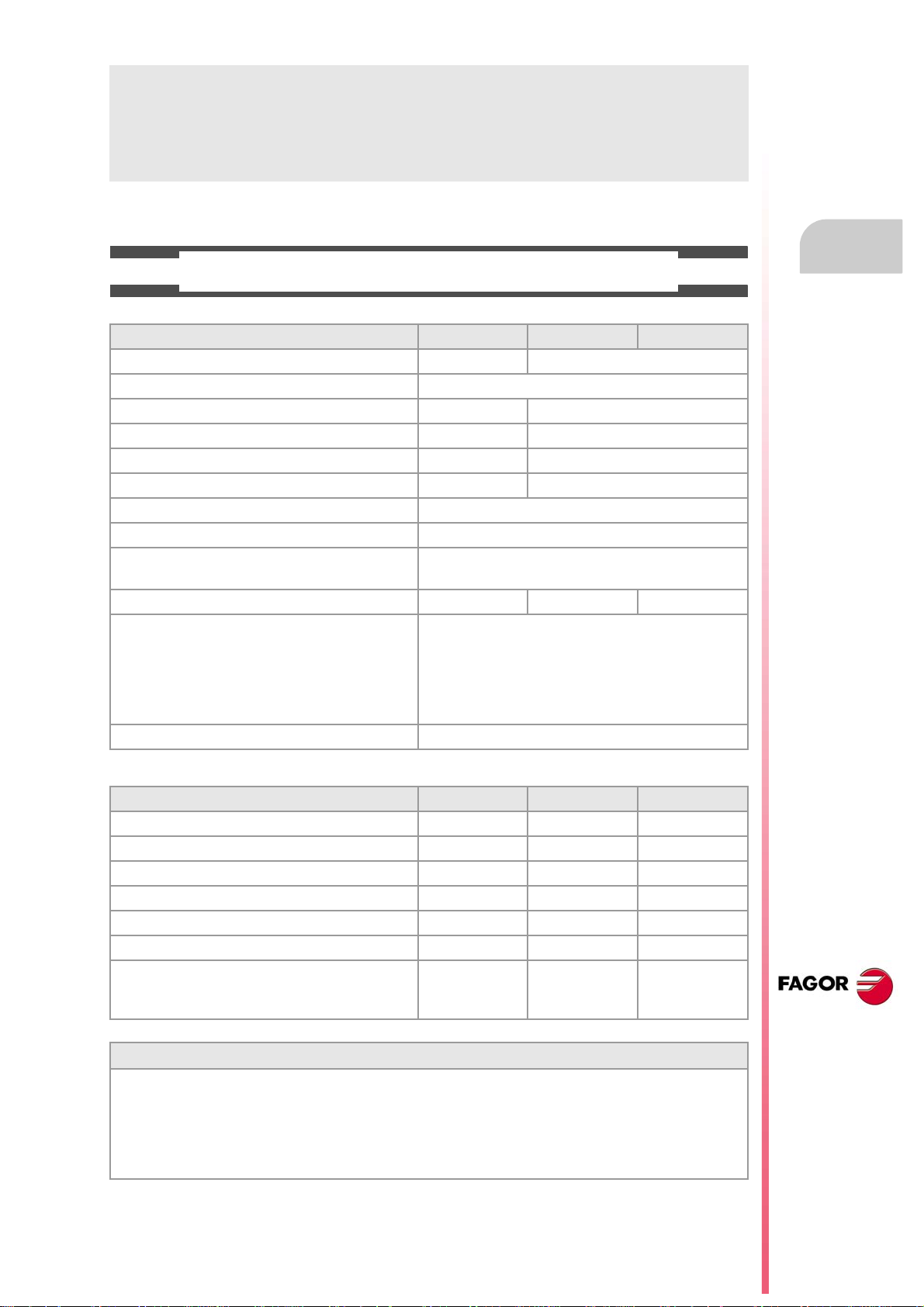
BASIC CHARACTERISTICS.
Basic characteristics. ·BL· ·OL· ·M· / ·T·
PC-based system. Closed system Open system
Operating system. Windows XP
Number of axes. 3 to 7 3 to 28
Number of spindles. 1 1 to 4
Number of tool magazines. 1 1 to 4
Number of execution channels. 1 1 to 4
Number of handwheels. 1 to 12
Type of servo system. Analog / Digital Sercos / Digital Mechatrolink
Communications. RS485 / RS422 / RS232
Ethernet
PCI expansion. No Option No
Integrated PLC.
PLC execution time.
Digital inputs / Digital outputs.
Marks / Registers.
Timers / Counters.
Symbols.
Block processing time. < 1 ms
< 1ms/K
1024 / 1024
8192 / 1024
512 / 256
Unlimited
Remote modules. RIOW RIO5 RIO70
Communication with the remote modules. CANopen CANopen CANfagor
Digital inputs per module. 8 16 or 32 16
Digital outputs per module. 8 24 or 48 16
Analog inputs per module. 4 4 8
Analog outputs per module. 4 4 4
Inputs for PT100 temperature sensors. 2 2 - - -
Feedback inputs. - - - - - - 4
Differential TTL
Sinusoidal 1 Vpp
Customizing.
PC-based open system, fully customizable.
INI configuration files.
FGUIM visual configuration tool.
Visual Basic®, Visual C++®, etc.
Internal databases in Microsoft® Access.
OPC compatible interface
CNC 8070
(REF. 1309)
·9·
Page 10
Programming manual
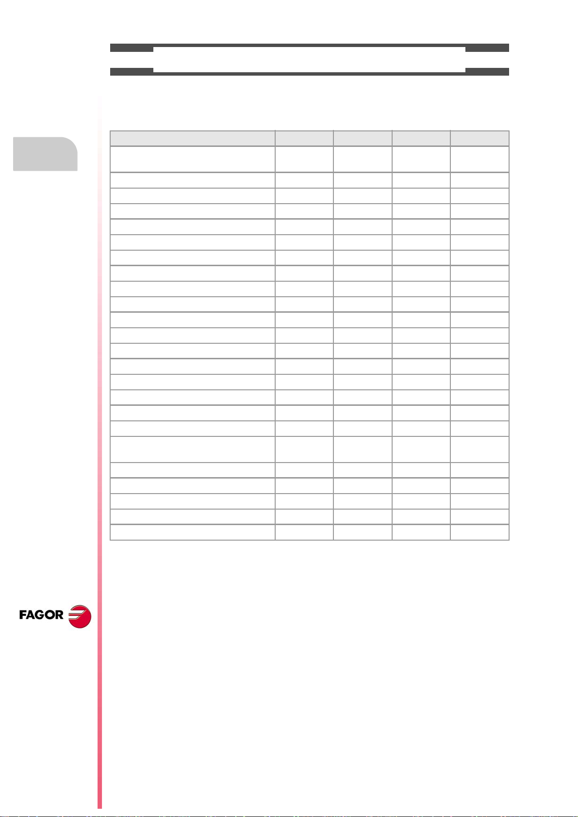
SOFTWARE OPTIONS.
Bear in mind that some of the features described in this manual depend on the software options that are
installed. The information of the following table is informative only; when purchasing the software options,
only the information provided in the ordering handbook is valid.
-BL- model -OL- model -M- model -T- model
Open system.
Access to the administrator mode.
Editing and simulation environment. - - - Standard Standard Standard
Number of execution channels 1 1 to 4 1 to 4 1 to 4
Number of axes 3 to 7 3 to 28 3 to 28 3 to 28
Number of spindles 1 1 to 4 1 to 4 1 to 4
Number of tool magazines 1 1 to 4 1 to 4 1 to 4
Number of interpolated axes (maximum) 4 28 - - - - - -
Limited to 4 interpolated axes Option Option Option Option
IEC 61131 language Option Option - - - - - -
HD graphics - - - Option Option Option
Conversational IIP - - - - - - Option Option
Non-Fagor digital drive Option Option - - - - - -
Tool radius compensation Option Option Standard Standard
"C" axis Option Option Standard Standard
Dynamic RTCP Option Option - - - Option
HSSA machining system. Option Option Standard Standard
Probing canned cycles - - - - - - Option Standard
Profile editor - - - - - - Standard Standard
Drilling ISO cycles for the OL model.
(G80, G81, G82, G83).
Tandem axes - - - Option - - - Option
Synchronism and cams Option Option - - - - - -
Tangential control Option Option - - - Standard
Volumetric compensation (up to 10 m³). Option Option Option Option
Volumetric compensation (more than 10 m³). Option Option Option Option
- - - Option - - - - - -
- - - Option - - - - - -
CNC 8070
(REF. 1309)
·10·
Page 11
Programming manual
DECLARATION OF CONFORMITY
The manufacturer:
Fagor Automation S. Coop.
Barrio de San Andrés Nº 19, C.P.20500, Mondragón -Guipúzcoa- (Spain).
Declares:
The manufacturer declares under their exclusive responsibility the conformity of the product:
8070 CNC
Consisting of the following modules and accessories:
8070-BL-ICU, 8070-OL-ICU
8070-BL-MCU, 8070-OL-MCU , 8070-OL-MCU-PCI
MONITOR-LCD-10K, MONITOR-LCD-15, MONITOR-SVGA-15
HORIZONTAL-KEYB, VERTICAL-KEYB, OP-PANEL
BATTERY, MOUSE UNIT
Remote Modules RIOW, RIO5, RIO70, RCS-S.
Note.Some additional characters may follow the model references indicated above. They all comply with the
directives listed here. However, compliance may be verified on the label of the unit itself.
Referred to by this declaration with following directives:
Low-voltage regulations.
IEC 60204-1:2005/A1:2008 Electrical equipment on machines. Part1. General requirements.
Regulation on electromagnetic compatibility.
EN 61131-2: 2007 PLC. Part 2. Equipment requirements and tests.
According to the European Community Directives 2006/95/EC on Low Voltage and 2004/108/EC
on Electromagnetic Compatibility and their updates.
In Mondragón, September 1st, 2013.
CNC 8070
(REF. 1309)
·11·
Page 12

Page 13
Programming manual
VERSION HISTORY
Here is a list of the features added to each manual reference. Each manual reference is valid for the
indicated software version and newer versions.
Ref. 0201
Software V01.00
First version. Milling model.
Ref. 0212
Software V01.10
New repositioning feedrate after tool inspection. • Machine parameter: REPOSFEED.
New treatment of the JOG keys. Different keys to select the axis and the
direction.
Know the dimensions of the kinematics on an axis. • Variable: (V.)A.HEADOF.xn
Keyboard simulation from the PLC. • Variable: (V.)G.KEY
Jog mode. Tool calibration with or without probe.
Jog mode. Automatic loading of zero offsets table.
Jog mode. Programming of feedrate "F" and spindle speed "S".
MDI mode. Block syntax check.
Utilities mode. Define protection passwords.
Block search. Define the first block.
Improved tool table.
Axis selection/deselection to move it with a handwheel.
Simulate the theoretical path.
Confirm the execution of a program pressing the [START] key in a mode other
than automatic.
General scaling factor. • New instruction, #SCALE.
Probe selection. • New instruction, #SELECT PROBE.
Probing canned cycles. • New instruction, #PROBE.
Programming of warnings. • New instruction, #WARNING.
Block repetition. • New instruction, #RPT.
Know the active general scaling factor. • Variable: (V.)G.SCALE
Knowing which is the active probe. • Variable: (V.)G.ACTIVPROBE
Improved programming of high speed machining. • #HSC instruction.
Improved programming of axis swapping. • Instructions #SET, #CALL, #FREE, #RENAME.
The number of macros in a program is now limited to 50. • Macros.
• Machine parameter: JOGKEYDEF.
Ref. 0501
Software V02.01
Windows XP operating system.
Emergency shutdown with battery (central unit PC104).
Multi-channel system, up to 4 channels. Swapping of axes and spindles,
communication and synchronization between channels, common arithmetic
parameters, access variables by channel, etc.
Multi-spindle system, up to 4 spindles.
Tool management with up to 4 magazines.
New languages (Basque and Portuguese). • Machine parameter: LANGUAGE.
Placing the vertical softkeys on the left or on the right. • Machine parameter: VMENU.
Tool radius compensation mode (G136/G137) by default • Machine parameter: IRCOMP.
OEM generic machine parameters. • Machine parameter: MTBPAR.
Reading Sercos variables from the CNC. • Machine parameter: DRIVEVAR.
Electronic-cam editor. • Machine parameter: CAM.
New behavior for rotary axes.
The "(V.).TM.MZWAIT " variable is not necessary in the subroutine associated
with M06.
Know the software version. • Variable: (V.)G.SOFTWARE
Variables related to loop adjustment. Gain setting via PLC. • Variables:
Variables related to loop adjustment. Position increment and sampling period. • Variables:
• Subroutine associated with M6.
• Variable: (V.).TM.MZWAIT
(V.)A.PLCFFGAIN.xn (V.)A.PLCACFGAIN.xn
(V.)A.PLCPROGAIN.xn
(V.)A.POSINC.xn (V.)A.TPOSINC.xn
(V.)A.PREVPOSINC.xn
CNC 8070
(REF. 1309)
·13·
Page 14
Programming manual
Software V02.01
Variables related to loop adjustment. Fine adjustment of feedrate,
acceleration and jerk.
Variables related to the feedback inputs. • Variables:
Optimize the reading and writing of variables from the PLC. Only the access
to the following variables will be asynchronous.
• The tool variables will be read asynchronously when the tool is neither
the active one nor in the magazine.
• The tool variables will be written asynchronously whether the tool is the
active one or not.
• The variables referred to local arithmetic parameters of the active levels
will be read and written asynchronously.
Spindle parking and unparking. • Instructions #PARK, #UNPARK.
Tool radius compensation.
• Behavior of the beginning and end of tool radius compensation when not
programming a movement.
• Changing the type of radius compensation while machining.
Via program, loading a tool in a specific magazine position.
Programming of modal subroutines. • New instruction, #MCALL.
Executing a block in a channel. • New instruction, #EXBLK.
Programming the number of repetitions in the block. • NR command.
Direct resolution of 2D and 3D pockets without requiring a softkey.
Simulating a canned cycle of the editor separately.
Importing DXF files from the program editor or from the profile editor.
Importing programs of the 8055/8055i CNC from the program editor.
Use a softkey to select the repositioning of the spindle after tool inspection.
Backup-restore utility.
Improved profile editor.
Assistance in the program editor. Contextual programming assistance.
• When programming "#", it shows the list of instructions.
• When programming "$", it shows the list of instructions.
• When programming "V.", it shows the list of variables.
Specific password for the machine parameters for kinematics.
Save the CAN configuration for testing it when starting up the system.
The diagnosis mode shows detailed information on the Sercos connection
(Type and version of the drive and motor connected to it).
It is possible to print all the information on the configuration from any section
of the diagnosis mode.
It is possible to simulate a cycle separately from the cycle editor.
Setup assistance. Oscilloscope, Bode diagram, circularity test.
• Variables:
(V.)A.FEED.xn (V.)A.TFEED.xn
(V.)A.ACCEL.xn (V.)A.TACCEL.xn
(V.)A.JERK.xn (V.)A.TJERK.xn
(V.)A.COUNTER.xn (V.)A.COUNTERST.xn
(V.)A.ASINUS.xn (V.)A.BSINUS.xn
• Reading and writing of variables from the PLC.
CNC 8070
(REF. 1309)
Ref. 0504
Software V02.03
New values of machine parameter SERPOWSE for the "Sercos II" board. • Machine parameters: SERPOWSE.
The simulated axes are ignored regarding the validation code.
Electronic cam programming (real coordinates). • New instruction, #CAM.
Synchronization of independent axis (real coordinates). • New instruction, #FOLLOW.
Movement of the independent axis. • New instruction, #MOVE.
DDSSetup mode.
G31. Temporary polar origin shift to the center of interpolation. • G31 function.
G112. Change the drive's parameter set. • G112 function.
Ref. 0509
Software V03.00
Lathe model. Machining canned cycles, lathe tool calibration, variables to
consult the geometry of lathe tools, etc.
Incline axis.
Permit using the G95 function in jog mode. • Machine parameter: FPRMAN.
Lathe model. Select graphics configuration. • Machine parameter: GRAPHTYPE.
Lathe model. Select axis configuration. • Machine parameter: GEOCONFIG.
Select the set of parameters for synchronization. • Machine parameter: SYNCSET.
"C" axis maintained. • Machine parameter: PERCAX.
Magazine-less system.
Ground tools for a turret magazine.
Variable to read the accumulated PLC offset. • Variable: (V.)[ch].A.ACTPLCOF.xn
Variable to obtain a linear estimation of the following error. • Variable: (V.)[ch].A.FLWEST.xn
Variables to read the instant value of feed-forward or AC-forward. • Variables:
Variable to know the line number of the file being executed. • Variable: (V.)[ch].G.LINEN
Variable to know what kind of cycle is active. • Variable: (V.)[ch].G.CYCLETYPEON
Variable to know the tool orientation. • Variable: (V.)[ch].G.TOOLDIR
(V.)[ch].A.ACTFFW.xn (V.)[ch].A.ACTACF.xn
·14·
Page 15
Programming manual
Software V03.00
Variable to know whether the HSC mode is active or not. • Variable: (V.)[ch].G.HSC
Variable to know the theoretical feedrate on 3D path. • Variable: (V.)[ch].G.F3D
Variable to know the number of the warning being displayed. • Variable: (V.)[ch].G.CNCWARNING
The variable (V.)G.CNCERR is now per channel. • Variable: (V.)G.CNCERR
Select the type of loop, open or closed, for the spindle. • New instruction, #SERVO.
Spindle synchronization. • New instruction, #SYNC.
Spindle synchronization. • New instruction, #TSYNC.
Spindle synchronization. • New instruction, #UNSYNC.
Select milling cycles at a lathe model. • New instruction, #MILLCY.
Select turning cycles at a milling model. • New instruction, #LATHECY.
Define a kinematics when activating the C axis. • #CYL instruction.
Define a kinematics when activating the C axis. • #FACE instruction.
Improved coordinate transformation (#CS/#ACS).
• Keep the part zero when deactivating the transformation.
• Working with 45º spindles. Select between the two choices.
• Keep the rotation of the plane axes with MODE 6.
G33. New parameter (Q1) to define the entry angle. • G33 function.
G63. Tool inspection is possible during rigid tapping. • G63 function.
Function G112 is not valid for the spindle. • G112 function.
New criteria when assuming a new master spindle in the channel.
Improved tool table.
• Instructions #CS, #ACS.
Ref. 0601
Software V03.01
Axis slaving. Configuring the default status of an axis slaving (coupling). • Machine parameters: LINKCANCEL.
Tool radius compensation. The way tool radius is canceled. • Machine parameters: COMPCANCEL.
Screen test on power-up, if any element is missing, it restores the relevant
backup.
Editing mode. Editing programs in the 8055 CNC language.
DDSSetup mode. Saving and loading the data of all the drives at the same
time.
Using the ":" character to program a comment in a part-program.
Variables. Geometry of the lathe tools.
Variables. Number of the tool in the claws of the changer arm. • Variables:
Automatic mode. It allows executing a program independently.
The instruction #EXEC does not issue an error if the channel is busy; the
instruction waits for the operation in progress to end.
The instruction #EXBLK does not issue an error if the channel is busy; the
instruction waits for the operation in progress to end.
(V.)TM.TOOLCH1[mz] (V.)TM.TOOLCH2[mz]
• #EXEC instruction.
• #EXBLK instruction.
Ref. 0606
Software V03.10
Feedrate. Maximum machining feedrate. • Machine parameter: MAXFEED.
Feedrate. Default machining feedrate when none has been programmed. • Machine parameter: DEFAULTFEED.
The user keys may be configured as jog keys. • Machine parameter: USERKEYDEF.
Disabling a keyboard or jog panel integrated into the CAN bus. • PLC mark: PANELOFF.
Handwheel with push-button. Selecting an axis sequentially for jogging it with
the handwheel.
New parameter to set whether or not the CNC sends the M, H, S functions to
the PLC during block search.
The CNC allows changing the spindle override during electronic threading
(G33) and in the threading canned cycles of the ·T· model (G86, G87 and their
equivalent of the cycle editor).
OEM machine parameters.
• Range of parameters that can be written from the part-program, from the
PLC or from the interface.
• Range of parameters affected by the change of units.
• Each parameter may have a different describing comment associated
with it.
Home search. New home searching method for spindles with home switch.
The spindle goes through the home switch twice.
The CNC displays the warnings generated at the drive.
M function table. New field to define whether the function is sent out to the PLC
or not during block search.
M function table. Each M function may have a different describing comment
associated with it.
General handwheel. The CNC may have several general handwheels.
General handwheel. A general handwheel can move several axes at the same
time.
Improvements in the looks of some softkeys of the editor.
Improvements in the looks of some softkeys of the graphics window.
Editing mode. Programming help files for OEM and global subroutines.
Editing mode. Help file with the list of available subroutines.
• PLC mark: NEXTMPGAXIS.
•
• Machine parameter: FUNPLC.
• Machine parameters:
THREADOVR, OVRFILTER.
• Field: MPLC.
• Field: COMMENT.
CNC 8070
(REF. 1309)
·15·
Page 16
Programming manual
Software V03.10
Editing mode. Improved contextual assistance.
Editing mode. New softkey for deactivating the contextual assistance.
Editing mode. Improvements in the looks of the softkeys.
The automatic mode offers a softkey for selecting the program that is being
edited.
In automatic and jog modes, the CNC shows the status of the _FEEDHOL
mark.
In automatic and jog modes, the CNC shows the status of the INHIBIT mark
of the axes and spindle.
Automatic mode. It shows information on all the spindles.
Jog mode. It shows information on all the spindles.
"Retrace" function.
Tangential control.
Tool table. New softkey for initializing the positions; T1 in position 1, T2 in
position 2, etc.
Tool table. New softkeys for copying and pasting the data of a tool offset.
The CNC checks whether the programmed turning direction (M3/M4) matches
the one preset in the tool table.
Generating the warranty registration report.
Hiding the window for errors and warnings.
M02/M30. There is no need to program M02 or M30 to end a part program. • Functions M02/M30.
Canceling the preset turning direction of a tool. • Variables: (V.)G.SPDLTURDIR
Change the maximum feedrate allowed in the channel from the PLC. • Variables: (V.)[ch].PLC.PLCG00FEED
Show the status of the emergency relay. • Variables: (V.)G.ERELAYST
HSC. New FAST mode. • #HSC instruction.
"C" axis. The #CYL instruction requires programming the radius. • #CYL instruction.
Improved block search.
Tool calibration.
• Manual calibration. When calibration is done, pressing [START] assumes
the new values.
• Semi-automatic calibration. Calibration of lathe tools.
• Semi-automatic calibration. When calibration is done, pressing [START]
assumes the new values.
• Automatic calibration. When calibration is done, the CNC assumes the
new values.
• PLC mark: _FEEDHOL.
• PLC mark: INHIBIT.
CNC 8070
(REF. 1309)
Ref. 0608
Software V03.11
Simulator Possibility to use the dongle (hardware key) in a network.
Line graphics. Improved resizing of the graphics on the screen.
"Retrace" function. Several improvements to the retrace function.
HSC. New command CORNER. • #HSC instruction.
The default value of some machine parameters is different for the CNC and
for the simulator installed on a PC.
G33. The override limitation is maintained while returning to the beginning of
the thread.
RTCP. Home search is now possible on the axes that are not involved in
RTCP.
Abort the execution of the program and resume it somewhere else. • New instruction, #ABORT.
• G33 function.
Ref. 0704 / Ref. 0706
Software V03.13
Sign criteria for tool offsets (dimensions) and tool wear. • Machine parameters: TOOLOFSG.
Define the tool wear with incremental or absolute values. • Variables:
Variables V.TM.TOOLCH1[mz] / V.TM.TOOLCH2[mz] may be written from
the PLC.
MDI mode. Cancel the block being executed while keeping the machining
conditions.
Software V03.14
MCU and ICU central unit. battery powered RAM. Connecting handwheels to
the central unit. local I/O. Local feedback inputs. Loca probes.
Define whether the spindle is homed automatically with the first movement or
not.
The application may be restarted while turning the CNC off.
The task window may be accessed by clicking on the OEM icon (top left of the
status bar).
The channels may be accessed by clicking on the icons of the status bar).
The pages of an operating mode may be accessed by clicking on the mode
name (top right of the status bar).
The turning speed limitation (G192) is also applied when the spindle is working
at constant turning speed (G97)
(V.)TM.TOOLCH1[mz] (V.)TM.TOOLCH2[mz].
• G192 function.
·16·
Page 17
Programming manual
Ref. 0707
Software V03.15
Know the type of hardware. • Variable: (V.)G.HARDTYPE
Theoretical tool feedrate along the path. • Variable: (V.)[ch].G.PATHFEED
Every time the diagnosis mode is accessed, the CNC creates the files
SystemInfo.txt and SercosInfo.txt.
PLC errors may have an additional data file associated with them, same as
PLC messages.
User tables. The zero offset table shows the spindles that may be activated
as C axis.
Zero offsets for the C axis.
The CNC shows a warning when a channel is expecting a tool that is being
used in another channel.
Ref. 0709
Software V03.16
Tandem spindles.
Diagnosis mode. Monitoring of the temperature of the CPU, board and
enclosure.
The CNC uses the combined feedback to calculate the velocity command, but
it uses the direct feedback to calculate the compensations, circularity test, etc.
The CNC does not assume any kinematics on power-up. • Machine parameters: KINID
Machine parameters: KINID
The CNC allows modifying the override while threading if it detects that the
feed forward (parameter FFWTYPE) is not active in a gear or if the active feed
forward is lower than 90%
Ref. 0712
Software V03.17
C axis maintained after executing M02, M30 or after an emergency or reset. • Machine parameter: PERCAX.
Ref. 0801
Software V03.20
The CNC has a different MTB folder for each type of software installed; MTB_T
for lathe, MTB_M for mill and MTB_MC for motion control.
By default, the feedback alarms of the analog axes are activated.
Set change.
• For the CNC to assume the new parameter set, it must wait for the PLC
to receive the confirmation of one of the marks GEAR1 to GEAR4.
• The gear change concludes when the PLC receives the confirmation
signal AUXEND.
• Sercos spindle. The set change only affects the drive when it implies a
change of gear ratio.
• The CNC lets change the gear of the slave axis or spindle of a tandem.
Coordinate latching with the help of a probe or a digital input. • Variables:
PLC. The PLC program can have several mnemonic files (extension "plc").
PLC. When defining each PLC error, it is possible to select whether it opens
the emergency relay or not.
PLC. Grouping the additional information text files in a single file.
PLC. Contact (ladder) editor.
Status of the local probes. • Variables: (V.)G.PRBST1 (V.)G.PRBST2.
Axis synchronization. Managing a rotary axis as an infinite axis making it
possible to increase the feedback count of the axis indefinitely (wihout limits)
regardless of the value of the module.
Errors and warnings.
• From the errors and warnings, it is possible to access the errors solving
(troubleshooting) manual.
• CNC errors between 10000 and 20000 are reserved for the OEM so he
can create his own warning or error texts in different languages.
Show a warning and interrupt program execution. • New instruction, #WARNINGSTOP.
Electronic cam programming (theoretical coordinates). • New instruction, #TCAM.
Dynamic distribution of the machining operations between channels. • New instruction, #DINDIST.
The CNC can park the main axes.
The axes may be programmed using the "?" wild card that refers to the axis
position in the channel.
Functions G130 (percentage of acceleration) and G132 (percentage of jerk)
may be applied to the spindles.
Profile editor. Axes coordinated with auto-scale and name of the axes.
Profile editor. Zoom and movement of the graphics area via keyboard.
Profile editor. At the lathe model, the orientation of the axes is defined by
parameter GRAPHTYPE.
Edisimu mode. Inclined plane programming assistance.
(V.)[ch].A.LATCH1.xn (V.)[ch].A.LATCH2.xn
• Variables: (V.)[ch].A.ACCUDIST.xn
•Wild card "?".
• Functions G130 and G132.
• Machine parameter: GRAPHTYPE.
CNC 8070
(REF. 1309)
·17·
Page 18
CNC 8070
(REF. 1309)
Programming manual
Software V03.20
Edisimu mode. To simulate the program, when pressing the "START" softkey,
the CNC assumes the real configuration of the spindles of the channel and the
configuration of the machine parameters. The starting coordinates for
simulation will be the real coordinates that the CNC had on power-up.
Edisimu mode. New window for consulting the status of the subroutines,
canned cycles, block repetition and loops.
Edisimu mode. The "START" softkey saves the program being edited.
Automatic mode. New functions and instructions that cancel the retrace
function.
Automatic mode. New window for consulting the status of the subroutines,
canned cycles, block repetition and loops.
Automatic mode. The [START] key saves the program being edited.
Diagnosis mode. Generate the Fagor file for error diagnosis.
Tool table. When selecting an incremental wear, it is possible to define the
maximum increment possible; by default 0.5 mm (0.019685 inch).
Machine parameters tables. Import and export leadscrew compensation
tables.
Within a work mode, select the different pages in reverse order using the
[SHIFT] key.
Setup assistance. Bode.
Interface related variables.
Ref. 0809
Software V04.00 (it does not include the features of version V03.21)
Unicode.
New language (Chinese).
In the machine parameter table, an icon indicates which parameters are
involved in parameter matching.
Handwheels. There can now be up to 12 handwheels. • Machine parameter: NMPG.
The CNC applies module compensation throughout the entire revolution of the
axis.
Home search moving the axis to the reference point. • Machine parameter: POSINREF.
PLC. There can now be up to 1024 PLC messages. • PLC resources: MSG.
PLC. There can now be up to 1024 PLC errors. • PLC resources: ERR.
Handwheels. Inhibit the handwheels of the system. • PLC mark: INHIBITMPG1/INHIBITMPG12.
Cancel spindle synchronization after executing M02, M30 or after an error or
a reset.
Positioning a turret magazine whether there is a tool in the indicated position
or not.
A channel maintains its master spindle after executing M02, M30 or after an
emergency or a reset or restarting the CNC.
Force the change of gears and/or of the parameter set of a Sercos drive • Variable: (V.)A.SETGE.xn
Set a machine coordinate. • G174 function.
There can now be up to 99 zero offsets. • G159 function.
There can now be up to 100 synchronization marks. • Instructions #MEET, #WAIT and #SIGNAL.
Select a turret position. • #ROTATEMZ instructions.
Axis synchronization. Managing a rotary axis as an infinite axis making it
possible to increase the feedback count of the axis indefinitely (wihout limits)
regardless of the value of the module.
Variables. The variable (V.)[ch].E.PROGSELECT can be written via partprogram, PLC and interface. This variable can only be written with the value
of ·0·
Variables. The following variables are valid for the spindle. • Variables: (V.)[ch].A.MEAS.sn
Profile editor.
• Programming in Polar coordinates.
• Programming in incremental coordinates.
• Best zoom, display part zero and auto-zoom from the keyboard.
• Improved softkey menu.
Jog mode. New softkey to turn the CNC off.
Jog mode. In handwheel mode, next to each axis, the CNC indicates whether
that axis has an individual handwheel associated with it or not.
Jog mode. The screen shows the tool dimensions.
Automatic mode. The screen shows the tool dimensions.
Handwheels. The general handwheels can move axes with an associated
individual handwheel.
Handwheels. Number of pulses sent by the handwheel since the system was
started up.
Feed handwheel.
Diagnosis mode. View the error and warning history issued by the CNC.
• Machine parameter: MODCOMP.
• Instructions #SYNC and #TSYNC.
• #ROTATEMZ instructions.
• #MASTERinstruction.
• Variables: (V.)[ch].A.PREVACCUDIST.xn
• Variables: (V.)[ch].E.PROGSELECT
(V.)[ch].A.ATIPMEAS.sn
(V.)[ch].A.MEASOF.sn
(V.)[ch].A.MEASOK.sn
(V.)[ch].A.MEASIN.sn
• Variables: (V.)G.HANDP[hw]
·18·
Page 19
Programming manual
Software V04.00 (it does not include the features of version V03.21)
Edisimu mode and PLC mode.
• New hotkey to redo an operation.
• The editor shows the line number.
• The option "Find/replace" permits selecting the search direction, up or
down. New softkey to look for the text without replacing it.
• The editor adjusts the long blocks to the size of the window dividing the
block into several lines.
• The editor offers hotkeys [CTRL]+[+] and [CTRL]+[–] to increase or
decrease the size of the editor font. If the CNC has a mouse with a wheel,
the [CTRL] key combined with this wheel can also be used to increase
and decrease the size of the text font.
• In large files (more than 200 kB), the editor cancels the syntax coloring.
• In large files (more than 200 kB), the editor does not save the program
when changing blocks; the editor saves the program when the user has
not modified the program for about 5 seconds.
Edisimu mode.
• Comments having an asterisk (*) and programmed at the beginning of the
block allow to group blocks. Blocks programmed between these
comments will be grouped and may be expanded or shrunk the same way
as the cycles or profiles.
• Having the "Hide cycles/profiles" option active, when the cursor moves
over a hidden element, it expands automatically; when the cursor moves
out of the element, it shrinks again.
• The editor offers the [ALT]+[–] hotkey to expand y hide cycles, profiles and
grouped blocks. If the CNC has a mouse, click on the symbol located to
the right of the cycle, profile or group of blocks to expand them and hide
them.
• In large files (more than 200 kB), the editor does not hide the canned
cycles or the profiles.
PLC mode. New softkeys to sort the files that make up the PLC project.
Ref. 0811
Software V03.21 (features not included in version V04.00)
There can now be up to 1024 PLC messages. • PLC resources: MSG.
There can now be up to 1024 PLC errors. • PLC resources: ERR.
Ref. 0907
Software V04.01
The CNC turns the internal fan on and off as necessary. The CNC turns the
fan on when the temperature exceeds 50 ºC (122 ºF) and turns it off when it
gets under 45 ºC (113 ºF).
Communication with servos (axis and spindle) and inverters (spindle) through
the Mechatrolink bus, in Mlink-I (17 bytes) and Mlink-II (17 or 32 bytes) mode.
Define the maximum acceleration and jerk allowed on the tool path. • Machine parameters:
Variable to know the following error (lag) when feedback combination is active. • Variables:
Variable to know the position value of the first feedback when feedback
combination is active.
Diagnosis mode. Monitor battery voltage.
MAXACCEL, MAXJERK.
• Variables:
(V.)[ch].G.MAXACCEL (V.)[ch].G.MAXJERK
(V.)[ch].A.FLWE.xn (V.)[ch].A.FLWACT.xn
• Variable: (V.)[ch].A.POSMOTOR.xn
Ref. 1007
Software V04.10 (it does not include the features of version V04.02)
New languages (Russian and Czech). • Machine parameter: LANGUAGE.
Cancel the inclined plane on start-up. • Machine parameter: CSCANCEL.
Handwheels. Setting a negative resolution reverses the axis moving direction. • Machine parameter: MPGRESOL.
Activate the rapid traverse for the automatic mode while executing a program. • Machine parameters: RAPIDEN, FRAPIDEN.
• PLC mark: EXRAPID.
Maximum axis machining feedrate. • Machine parameter: MAXFEED.
Management of several keyboards. • Machine parameter: NKEYBD.
Configure the serial line as RS232, RS422 or RS485. • Machine parameter: RSTYPE.
Enable the HBLS handwheel. • Machine parameter: HBLS.
Selecting the type of PLC (IEC61131 or Fagor). • Machine parameter: PLCTYPE
RTCP. On tilting tables, rotate the part coordinate system when rotating the
table.
PLC. There are now 512 PLC timers. • PLC resources: Timers.
PLC. Management of spindle M functions (M3, M4 and M5) from the PLC. • PLC marks: PLCM3, PLCM4 and PLCM5.
New look for the interface.
MDI mode. The feedrate set in MDI/MDA mode will become the new feedrate
for the jog and automatic modes.
Jog mode. Set or activate a zero offset or fixture offset.
Jog mode. The screen shows an icon that represents the type of tool.
Automatic mode. The screen shows an icon that represents the type of tool.
• Kinematics TYPE9 through TYPE12.
CNC 8070
(REF. 1309)
·19·
Page 20
Programming manual
Software V04.10 (it does not include the features of version V04.02)
Editing mode. Use a template for part programs.
Utilities mode. Encrypt files.
The CNC allows eliminating certain errors by pressing the [ESC] key without
having to do a reset.
M functions with an associated subroutine.
The CNC admits function G174 for axes in DRO mode and spindles. • G174 function.
Detailed CNC status in jog mode. • Variable: (V.)[ch].G.CNCMANSTATUS
Detailed CNC status in automatic mode. • Variable: (V.)[ch].G.CNCAUTSTATUS
Know the axes selected for home search, repositioning, coordinate preset or
movement to a coordinate.
Know the current position of the main rotary axes of the kinematics (third
axis).
Know the target position of the main rotary axes of the kinematics (third axis). • Variable: (V.)[ch].G.TOOLORIT1
Cancel the name change for axes and spindles (#RENAME) after executing
M02 or M30, after a reset or at the beginning of a new part-program in the same
channel.
Graphic environment. Simulate the real path, but enlarging the error with
respect to the theoretical path.
• Variable: (V.)[ch].G.SELECTEDAXIS
• Variable: (V.)[ch].G.POSROTT
(V.)[ch].G.TOOLORIT2
• #RENAME instruction.
Ref. 1010
Software V04.02 (features not included in version V04.10)
New language (Russian). • Machine parameter: LANGUAGE.
Activate the rapid traverse for the automatic mode while executing a program. • Machine parameters: RAPIDEN, FRAPIDEN.
• PLC mark: EXRAPID.
Maximum axis machining feedrate. • Machine parameter: MAXFEED.
Management of several keyboards. • Machine parameter: NKEYBD.
Configure the serial line as RS232, RS422 or RS485. • Machine parameter: RSTYPE.
Synchronize spindles without forcing a set change. • Machine parameter: SYNCSET.
Mechatrolink. Activate the drive options. • Machine parameter: OPTION.
RTCP. On tilting tables, rotate the part coordinate system when rotating the
table.
MDI mode. The feedrate set in MDI/MDA mode will become the new feedrate
for the jog and automatic modes.
Jog mode. Set or activate a zero offset or fixture offset.
The CNC admits function G174 for axes in DRO mode and spindles. • G174 function.
Detailed CNC status in jog mode. • Variable: (V.)[ch].G.CNCMANSTATUS
Detailed CNC status in automatic mode. • Variable: (V.)[ch].G.CNCAUTSTATUS
Know the axes selected for home search, repositioning, coordinate preset or
movement to a coordinate.
Know the current position of the main rotary axes of the kinematics (third
axis).
Know the target position of the main rotary axes of the kinematics (third axis). • Variable: (V.)[ch].G.TOOLORIT1
Know the status of a cam. • Variable: (V.)G.CAMST[cam]
Modify the range of the slave axis when activating the cam. • Variable: (V.)G.CAM[cam][index]
Set 0% feedrate override via PLC. • Variable: (V.)[ch].PLC.FRO
Cancel the name change for axes and spindles (#RENAME) after executing
M02 or M30, after a reset or at the beginning of a new part-program in the same
channel.
Graphic environment. Simulate the real path, but enlarging the error with
respect to the theoretical path.
Edisimu mode. The simulation assumes the origins that are active for
execution.
• Kinematics TYPE9 through TYPE12.
• Variable: (V.)[ch].G.SELECTEDAXIS
• Variable: (V.)[ch].G.POSROTT
(V.)[ch].G.TOOLORIT2
• #RENAME instruction.
CNC 8070
(REF. 1309)
·20·
Ref. 1107
Software V04.11
Synchronized switching. • Variables:
(V.)G.TON (V.)G.TOF
(V.)G.PON (V.)G.POF
• Statement: #SWTOUT
Ref. 1304
Software V04.20
Configure how to operate the CNC. Access work modes using hotkeys or from
the softkey menu.
Configure how to use the softkey menu, either using menus and submenus
(there are different softkey levels within a work mode) or using popup menus
(there is only 1 softkey menu, without submenus).
Maximum safety limit for feedrate. • Machine parameter: FLIMIT.
Maximum safety speed limit. • Machine parameter: SLIMIT.
Interruption subroutines per channel. • Programming instructions: #REPOS.
There may be up to 30 OEM subroutines per channel now (G180-G189 /
G380-G399).
• Machine parameter: HMITYPE.
• Machine parameter: SFTYPE.
Page 21
Programming manual
Software V04.20
The OEM subroutines may be executed either in a non-modal (G180, G181,
etc) or in a modal way (MG180, MG181, etc).
The operation of M19 with subroutine has changed. • Function: M19.
Know the status of a cam. • Variable: (V.)G.CAMST[cam]
Modify the range of the slave axis when activating the cam. • Variable: (V.)G.CAM[cam][index]
Set 0% feedrate override via PLC. • Variable: (V.)[ch].PLC.FRO
Detailed CNC status in automatic mode. New values. • Variable: (V.)[ch].G.CNCAUTSTATUS
Active zero offset. • Variable: (V.)[ch].G.EXTORG
The CNC can execute programs of the 8055 MC and 8055 TC models made
up with conversational canned cycles including geometric assistance.
Tool table. Assign a name or text to any of the 4 "custom" parameters available
in each tool.
Operation with touch-screen model.
New tool inspection.
New HD graphics.
EDISIMU mode. Geometric help editor.
Jog mode. Tool calibration pages show the data of the tool to be calibrated.
MDI/MDA mode. The CNC can execute blocks when the execution of the
program is interrupted.
Automatic mode. Program simulation with the possibility to go into execution.
In this mode, it is possible to simulate a program, interrupt it at a point and start
execution from that point on.
Software V04.21
New model LCD-10K. • Variables:
Software V04.22
Set the zero offsets with a coarse part and a fine part. • Variables:
Cancel mirror image (G11/G12/G13/G14) after M30 and reset.
Software V04.24
Additional negative command pulse for analog axes. • Variable:
The SPDLEREV mark (reverse turning direction) affects the spindle in M19. • Variable:
Functions M02, M30 and reset do not cancel the speed limit function G192. • Function G192.
Functions M02, M30 and reset do not cancel the constant surface speed (CSS)
function.
Software V04.25
Synchronized switching. • Variables:
Error programmed in HSC mode. • Variable:
The HSC FAST mode may be used to adjust the chordal error (parameter E). • Statement: #HSC
The CNC will load into RAM memory the subroutines having the extension .fst.
If function G95 is active and the spindle does not have an encoder, the CNC
will use the programmed theoretical rpm to calculate the feedrate.
(V.)MPMAN.JOGKEYDEF[jk]
(V.)MPMAN.USERKEYDEF[uk]
(V.)[ch].A.ADDORG.xn
(V.)[ch].A.COARSEORG.xn
(V.)[ch].A.FINEORG.xn
(V.)[ch].A.COARSEORGT[nb].xn
(V.)[ch].A.FINEORGT[nb].xn
(V.)[ch].MPA.BAKANOUT[set].xn
(V.)[ch].MPA.M19SPDLEREV.xn
• Function G96.
(V.)G.TON (V.)G.TOF
(V.)G.PON (V.)G.POF
• Statement: #SWTOUT
(V.)[ch].G.CONTERROR
• Function G95.
Ref. 1305
Software V04.26
New model LCD-10K.
New model LCD-15.
New keyboard VERTICAL-KEYB.
New keyboard HORIZONTAL-KEYB.
New operator panel OP-PANEL.
Keep the longitudinal axis when changing planes (G17/G18/G19). • Function G17/G18/G19.
The M3/M4/M5 functions cancel the C axis and set the spindle in open loop.
Programs with ".mod" extension may be modified when they are interrupted
using "cancel and resume".
• Machine parameters:
JOGKEYDEF n
USERKEYDEF n
• Variables:
(V.)MPMAN.JOGKEYDEF[jk]
(V.)MPMAN.USERKEYDEF[uk]
CNC 8070
(REF. 1309)
·21·
Page 22

Programming manual
Ref. 1309
Software V04.27
The model LCD-10K (front mounting) is removed.
The model LCD-15 (front mounting) is removed.
The module OP-PANEL-H/E is removed.
The module JOG-PANEL is removed.
The module KB-PANEL-H is removed.
Virtual tool axis. • Statement: #VIRTAX
• Variables:
(V.)[ch].G.VIRTAXIS
(V.)[ch].G.VIRTAXST
PWM (Pulse-Width Modulation) • Statement: #PWMOUT
Modify the simulation speed via PLC. • Variable: (V.)PLC.SIMUSPEED
Execute subroutine as a single block. • Statement: #RETDSBLK
(V.)[ch].A.VIRTAXOF.xn
• Variables:
(V.)G.PWMON
(V.)G.PWMFREQ
(V.)G.PWMDUTY
(V.)PLC.PWMFREQ
(V.)PLC.PWMDUTY
CNC 8070
(REF. 1309)
·22·
Page 23
Programming manual
SAFETY CONDITIONS
Read the following safety measures in order to prevent harming people or damage to this product and those
products connected to it. Fagor Automation shall not be held responsible of any physical damage or
defective unit resulting from not complying with these basic safety regulations.
Before start-up, verify that the machine that integrates this CNC meets the 89/392/CEE Directive.
PRECAUTIONS BEFORE CLEANING THE UNIT
If the CNC does not turn on when actuating the start-up switch, verify the connections.
Do not get into the inside of the unit. Only personnel authorized by Fagor Automation may manipulate the
Do not handle the connectors with the unit
connected to AC power.
inside of this unit.
Before manipulating the connectors (inputs/outputs, feedback, etc.)
make sure that the unit is not connected to AC power.
PRECAUTIONS DURING REPAIR
In case of a malfunction or failure, disconnect it and call the technical service.
Do not get into the inside of the unit. Only personnel authorized by Fagor Automation may manipulate the
inside of this unit.
Do not handle the connectors with the unit
connected to AC power.
Before manipulating the connectors (inputs/outputs, feedback, etc.)
make sure that the unit is not connected to AC power.
PRECAUTIONS AGAINST PERSONAL DAMAGE
Interconnection of modules. Use the connection cables provided with the unit.
Use proper cables. To prevent risks, use the proper cables for mains, Sercos and Bus
CAN recommended for this unit.
In order to avoid electrical shock at the central unit, use the proper
power (mains) cable. Use 3-wire power cables (one for ground
connection).
Avoid electrical overloads. In order to avoid electrical discharges and fire hazards, do not apply
electrical voltage outside the range selected on the rear panel of the
central unit.
Ground connection. In order to avoid electrical discharges, connect the ground terminals
of all the modules to the main ground terminal. Before connecting the
inputs and outputs of this unit, make sure that all the grounding
connections are properly made.
In order to avoid electrical shock, before turning the unit on verify that
the ground connection is properly made.
Do not work in humid environments. In order to avoid electrical discharges, always work under 90% of
relative humidity (non-condensing) and 45 ºC (113 ºF).
Do not work in explosive environments. In order to avoid risks or damages, do no work in explosive
environments.
CNC 8070
(REF. 1309)
·23·
Page 24
Programming manual
PRECAUTIONS AGAINST PRODUCT DAMAGE
Working environment. This unit is ready to be used in industr ial environments complying with
the directives and regulations effective in the European Community.
Fagor Automation shall not be held responsible for any damage
suffered or caused by the CNC when installed in other environments
(residential or homes).
Install the unit in the right place. It is recommended, whenever possible, to install the CNC away from
coolants, chemical product, blows, etc. that could damage it.
This unit complies with the European directives on electromagnetic
compatibility. Nevertheless, it is recommended to keep it away from
sources of electromagnetic disturbance such as:
Powerful loads connected to the same AC power line as this
equipment.
Nearby portable transmitters (Radio-telephones, Ham radio
transmitters).
Nearby radio/TV transmitters.
Nearby arc welding machines.
Nearby High Voltage power lines.
Enclosures. The manufacturer is responsible of assuring that the enclosure
involving the equipment meets all the currently effective directives of
the European Community.
Avoid disturbances coming from the
machine.
Use the proper power supply. Use an external regulated 24 Vdc power supply for the keyboard and
Grounding of the power supply. The zero volt point of the external power supply must be connected
Analog inputs and outputs connection. Use shielded cables connecting all their meshes to the corresponding
Ambient conditions. The storage temperature must be between +5 ºC and +45 ºC (41 ºF
Central unit enclosure. Make sure that the needed gap is kept between the central unit and
Main AC power switch. This switch must be easy to access and at a distance between 0.7 and
The machine must have all the interference generating elements
(relay coils, contactors, motors, etc.) uncoupled.
the remote modules.
to the main ground point of the machine.
pin.
and 113 ºF).
The storage temperature must be between -25 ºC and 70 ºC (-13 ºF
and 158 ºF).
each wall of the enclosure.
Use a DC fan to improve enclosure ventilation.
1.7 m (2.3 and 5.6 ft) off the floor.
CNC 8070
(REF. 1309)
·24·
PROTECTIONS OF THE UNIT ITSELF
Remote modules. All the digital inputs and outputs have galvanic isolation via
optocouplers between the CNC circuitry and the outside.
Page 25
Programming manual
i
SAFETY SYMBOLS
Symbols that may appear on the manual.
Danger or prohibition symbol.
It indicates actions or operations that may hurt people or damage products.
Warning symbol.
It indicates situations that certain operations could cause and the suggested actions to prevent them.
Obligation symbol.
It indicates actions and operations that must be carried out.
Information symbol.
It indicates notes, warnings and advises.
Symbols that the product may carry.
Ground protection symbol.
It indicates that that point must be under voltage.
CNC 8070
(REF. 1309)
·25·
Page 26

Page 27
Programming manual
WARRANTY TERMS
INITIAL WARRANTY
All products manufactured or marketed by FAGOR carry a 12-month warranty for the end user which could
be controlled by the our service network by means of the warranty control system established by FAGOR
for this purpose.
In order to prevent the possibility of having the time period from the time a product leaves our warehouse
until the end user actually receives it run against this 12-month warranty, FAGOR has set up a warranty
control system based on having the manufacturer or agent inform FAGOR of the destination, identification
and on-machine installation date, by filling out the document accompanying each FAGOR product in the
warranty envelope. This system, besides assuring a full year of warranty to the end user, enables our service
network to know about FAGOR equipment coming from other countries into their area of responsibility.
The warranty starting date will be the one appearing as the installation date on the above mentioned
document. FAGOR offers the manufacturer or agent 12 months to sell and install the product. This means
that the warranty starting date may be up to one year after the product has left our warehouse so long as
the warranty control sheet has been sent back to us. This translates into the extension of warranty period
to two years since the product left our warehouse. If this sheet has not been sent to us, the warranty period
ends 15 months from when the product left our warehouse.
This warranty covers all costs of material and labour involved in repairs at FAGOR carried out to correct
malfunctions in the equipment. FAGOR undertakes to repair or replace their products within the period from
the moment manufacture begins until 8 years after the date on which it disappears from the catalogue.
It is entirely up to FAGOR to determine whether the repair is or not under warranty.
EXCLUDING CLAUSES
Repairs will be carried out on our premises. Therefore, all expenses incurred as a result of trips made by
technical personnel to carry out equipment repairs, despite these being within the above-mentioned period
of warranty, are not covered by the warranty.
Said warranty will be applied whenever the equipment has been installed in accordance with instructions,
has not be mistreated, has not been damaged by accident or by negligence and has not been tampered
with by personnel not authorised by FAGOR. If, once servicing or repairs have been made, the cause of
the malfunction cannot be attributed to said elements, the customer is obliged to cover the expenses
incurred, in accordance with the tariffs in force.
Other warranties, implicit or explicit, are not covered and FAGOR AUTOMATION cannot be held responsible
for other damages which may occur.
CNC 8070
(REF. 1309)
·27·
Page 28
Programming manual
WARRANTY ON REPAIRS
In a similar way to the initial warranty, FAGOR offers a warranty on standard repairs according to the
following conditions:
PERIOD 12 months.
CONCEPT Covers parts and labor for repairs (or replacements) at the
network's own facilities.
EXCLUDING CLAUSES The same as those applied regarding the chapter on initial
warranty. If the repair is carried out within the warranty period, the
warranty extension has no effect.
When the customer does not choose the standard repair and just the faulty material has been replaced,
the warranty will cover just the replaced parts or components within 12 months.
For sold parts the warranty is 12 moths length.
SERVICE CONTRACTS
The SERVICE CONTRACT is available for the distributor or manufacturer who buys and installs our CNC
systems.
CNC 8070
(REF. 1309)
·28·
Page 29

Programming manual
MATERIAL RETURNING TERMS
When sending the central nit or the remote modules, pack them in its original package and packaging
material. If the original packaging material is not available, pack it as follows:
1 Get a cardboard box whose three inside dimensions are at least 15 cm (6 inches) larger than those
of the unit. The cardboard being used to make the box must have a resistance of 170 Kg (375 lb.).
2 Attach a label indicating the owner of the unit, person to contact, type of unit and serial number. In case
of malfunction also indicate symptom and a brief description of the problem.
3 Wrap the unit in a polyethylene roll or similar material to protect it. When sending a central unit with
monitor, protect especially the screen.
4 Pad the unit inside the cardboard box with poly-utherane foam on all sides.
5 Seal the cardboard box with packing tape or industrial staples.
CNC 8070
(REF. 1309)
·29·
Page 30

Page 31

Programming manual
CNC MAINTENANCE
CLEANING
The accumulated dirt inside the unit may act as a screen preventing the proper dissipation of the heat
generated by the internal circuitry which could result in a harmful overheating of the unit and, consequently,
possible malfunctions. Accumulated dirt can sometimes act as an electrical conductor and short-circuit the
internal circuitry, especially under high humidity conditions.
To clean the operator panel and the monitor, a smooth cloth should be used which has been dipped into
de-ionized water and /or non abrasive dish-washer soap (liquid, never powder) or 75º alcohol. Do not use
highly compressed air to clean the unit because it could generate electrostatic discharges.
The plastics used on the front panel are resistant to grease and mineral oils, bases and bleach, dissolved
detergents and alcohol. Avoid the action of solvents such as chlorine hydrocarbons, venzole, esters and
ether which can damage the plastics used to make the unit’s front panel.
PRECAUTIONS BEFORE CLEANING THE UNIT
Fagor Automation shall not be held responsible for any material or physical damage derived from the
violation of these basic safety requirements.
• Do not handle the connectors with the unit connected to AC power. Before handling these connectors
(I/O, feedback, etc.), make sure that the unit is not connected to main AC power.
• Do not get into the inside of the unit. Only personnel authorized by Fagor Automation may manipulate
the inside of this unit.
• If the CNC does not turn on when actuating the start-up switch, verify the connections.
CNC 8070
(REF. 1309)
·31·
Page 32

Page 33

CREATING A PROGRAM.
1.1 Programming languages.
The CNC has its own programming language described in this manual. The program is edited
block by block and each one may be written in ISO language or in High level language. See
"1.3 Program block structure." on page 37.
When editing high level commands, the editor offers a list of available commands.
8055 language.
Programs can also be edited in the 8055 CNC language. Programming in 8055 CNC
language is enabled from the part-program editor. Refer to the operating manual to enable
this option.
This manual does not describe the 8055 language; refer to the specific documentation for
this product. Obviously, since this CNC and the 8055 are two functionally different products,
some concepts may be different.
1
CNC 8070
(REF. 1309)
·33·
Page 34
1.
N10
N20
N30
N40
CNC program
Block
· · ·
Block
Subroutine
Block
· · ·
Block
Program body
Block
Programming manual
1.2 Program structure.
A CNC program consists of a set of blocks or instructions that properly organized, in
subroutines or in the program body, provide the CNC with the necessary data to machine
the desired part.
Each block contains all the functions or command necessary to execute an operation that
may be machining, preparing the cutting conditions, controlling the elements of the machine,
etc.
Program structure.
CREATING A PROGRAM.
%example
(Name of the program)
N5 F550 S1000 M3 M8 T1 D1
(Sets the machining conditions)
N6 G0 X0 Y0
(Positioning)
N10 G1 G90 X100
N20 Y50
N30 X0
N40 Y0
(Machining)
N50 M30
(End of program)
The CNC program may consist of several local subroutines and the body of the program.
The local subroutines must be defined at the beginning of the program.
CNC 8070
(REF. 1309)
·34·
Page 35
Programming manual
1.2.1 Program body.
The body of the program has the following structure.
Header The header indicates the beginning of the body of the program.
Program blocks It is the main part of the program, the one containing
End of program
Program header.
The header of the program is a block consisting of the "%" character followed by the name
of the program. The name of the program may be up to 14 characters long and may consist
of uppercase and lowercase characters as well as numbers (no blank spaces are allowed).
The header must be programmed when the program has local
subroutines.
movements, operations, etc.
1.
%0123
%PROGRAM
%PART923R
The header must be programmed when the program contains local subroutines; otherwise,
programming the header is optional.
The name defined in the header has nothing to do with the name of the file. The two may
be different.
Program body.
The body of the program consists of blocks in charge of executing operations, movements,
etc.
End of the program.
The end of the program body is defined by functions "M02" or "M30" and they are equivalent.
There is no need to program these functions; when reaching the end of the program without
executing any of them, the CNC ends the execution and shows a warning indicating that they
are missing.
M30
M02
Program structure.
CREATING A PROGRAM.
The CNC behaves differently when reaching the end of the program depending on whether
the M02 / M30 has been programmed or not
With M02/M30 Without
M02/M30
The CNC selects the first block of the program. Yes Yes
The CNC stops the spindle. Yes No
The CNC assumes the initial conditions. Yes (*) No
The CNC initializes the cutting conditions. Yes No
(*) Stopping the spindle depends on the setting of machine parameter SPDLSTOP.
CNC 8070
(REF. 1309)
·35·
Page 36
1.2.2 The subroutines.
1
3
2
4
%L POINTS
G01 X·· Y·· (Point 2)
G01 X·· Y·· (Point 3)
G01 X·· Y·· (Point 4)
M17
%PROGRAM
G81 X·· Y·· (Point 1. Center punching definition)
LL POINTS (call to a subroutine)
G81 X·· Y·· (Point 1. Center punching definition)
LL POINTS (call to a subroutine)
G84 X·· Y·· (Point 1. Center punching definition)
LL POINTS (call to a subroutine)
G80
M30
A subroutine is a set of blocks that, once properly identified, may be called upon several times
from another subroutine or from the program. Subroutines are normally used for defining a
bunch of operations or movements that are repeated several times throughout the program.
See chapter "12 Subroutines.".
Types of subroutines.
Programming manual
1.
Program structure.
CREATING A PROGRAM.
The CNC has two types of subroutines, namely local and global. There is also a third type
available, OEM subroutines, that are a special case of a global subroutine defined by the
OEM.
Global subroutines.
The global subroutine is stored in CNC memory as an independent program. This subroutine
may be called upon from any program or subroutine being executed.
Local subroutines.
The local subroutine is defined as part of a program. This subroutine may only be called upon
from the program where it has been defined.
A program can have several local subroutines; but they all must be defined before the body
of the program. A local subroutine can call a second local subroutine with the condition that
the calling subroutine be defined after the one being called.
CNC 8070
(REF. 1309)
·36·
Page 37

Programming manual
1.3 Program block structure.
The blocks comprising the subroutines or the program body may be defined by commands
in ISO code or in high-level language. Each block must be written in either language but not
mixed; a program may combine blocks written in both languages. Empty blocks (empty lines)
are also allowed.
In either language, it is also possible to use any type of arithmetic, relational or logic
expression.
Programming in ISO code.
It is especially designed to control the movement of the axes because it provides movement
data and conditions as well as feedrate and speed. Some of the available commands are:
• Preparatory functions for movement establishing the geometry and work conditions such
as linear and circular interpolations, threading, canned cycles, etc.
• Functions to control cutting conditions such as feedrate of the axes, spindle speed and
accelerations.
• Functions to control the tools.
• Additional functions containing technological instructions.
• Definition of position values.
High-level language programming.
This language provides the user with a set of control commands with a terminology similar
to the one used by other languages, such as $IF, $GOTO, #MSG, #HSC, etc. Some of the
available commands are:
• Programming instructions.
• Flow controlling instructions to make loops and jumps within the program.
• To define and call upon subroutines with local parameters where a local variable is the
one only known to the subroutine where it has been defined.
It is also possible to use any type of arithmetic, relational or logic expression.
1.
Program block structure.
CREATING A PROGRAM.
Arithmetic parameters, variables, constants and arithmetic
expressions.
Constants, arithmetic parameters, variables and arithmetic expressions may be used from
ISO blocks as well as from high level commands.
CNC 8070
(REF. 1309)
·37·
Page 38

1.
1.3.1 Programming in ISO code.
Program block structure.
CREATING A PROGRAM.
Programming manual
ISO-coded functions consist of letters and numbers. The letters are "N", "G", "F", "S", "T",
"D", "M", "H", "NR" plus those identifying the axes.
The numbers include digits "0" through "9", the "+" and "-" signs and the decimal point ".".
Likewise, the numerical format may be replaced by a parameter, variable or arithmetic
expression whose result is a number.
Programming allows blank spaces between letters, numbers and a sign as well as not using
the sign with positive values.
Block structure.
A block may have the following functions, but needs not contain all of them. The data has
no set order, it may be programmed anywhere in the block. The only exception being the
block-skip condition and the block identification which must always be programmed at the
beginning.
/N—G—G—X..C—F—S—T—D—M—H—NR—
·/· Block skip condition.
If the block-skip mark is active, the CNC will skip the blocks having this character (not
executing them) and will go on to the next block.
The CNC reads several blocks ahead of the one in execution, in order to calculate in advance
the path to travel. The block-skip condition is examined at the time when the block is read.
·N· Block identification.
The block identification must be programmed when the block is used as the destination of
references or jumps. In this case, it is recommended to program it alone in the block. It may
be represented in two ways:
• The letter "N" followed by the block number (0-4294967295) and the ":" character (only
when the label is used as the destination of a block jump); they need not follow a particular
order or be consecutive.
If the label is not a jump target and is programmed without ":", it may go in any position
of the block, not necessarily at the beginning.
• "[<name>]" type labels, where <name> may be up to 14 characters long and may consist
of uppercase and lowercase characters as well as numbers (no blank spaces are
allowed).
Both types of data may be programmed in the same block.
N10: X12 T1 D1
[CYCLE] G81 I67
X34 N10 S100 M3
·G· Preparatory functions.
G functions set the geometry and work conditions such as linear and circular interpolations,
chamfers, canned cycles, etc. See "1.5 List of "G" functions." on page 42.
CNC 8070
(REF. 1309)
·38·
·X..C· Coordinates of the point
These functions set the movement of the axes. See "1.4 Programming of the axes." on page
41.
Depending on the units, the programming format will be:
• In millimeters, format ±5.4 (5 integers and 4 decimals).
• In inches, format ±4.5 (4 integers and 5 decimals).
·F· Axis feedrate.
The feedrate is represented by the letter "F" followed by the desired feedrate value.
Page 39

Programming manual
·S· Spindle speed
This function sets the spindle speed.
The spindle name is defined by 1 or 2 characters. The first character is the letter S and the
second character is optional, it must be a numerical suffix between 1 and 9. This way, the
name of the spindles may be within the range S, S1 ... S9.
The feedrate is represented by the axis letter followed by the target position for the axis. For
spindles like S1, S2, etc. the "=" sign must be included between the axis name and the speed.
S1000
S1=334
·T· Tool number.
This function selects the tool to be used to carry out the programmed machining operation.
The tool is represented by the letter "T" followed by the tool number (0-4294967295).
·D· Tool offset number.
This function selects the tool offset. The tool offset is represented by the letter "D" followed
by the tool offset number. The number of offsets available for each tool is defined in the tool
table.
·M H· Auxiliary functions.
1.
Program block structure.
CREATING A PROGRAM.
With the auxiliary functions, it is possible to control machine elements such as spindle turning
direction, coolant, etc. These functions are represented by the letters "M" or "H" followed by
the function number (0-65535)
·NR· Number of block repetitions.
It indicates the number of times the block will be executed. It can only be programmed in
blocks containing a movement.
If the block is under the influence of a modal canned cycle, the latter will be repeated as many
times as the block repetition has been programmed. When programming NR0, the
movements will be executed, but the modal canned cycle is not executed at the end of each
one.
G91 G01 X34.678 F150 NR4
Block comment .
Any comment may be associated with the blocks. When executing the program, the CNC
ignores this information.
The CNC offers various methods to include comments in the program. See "1.8 Comment
programming." on page 50.
CNC 8070
(REF. 1309)
·39·
Page 40

1.3.2 High-level language programming.
The commands of high level language are made up of control instructions "#" and flow control
instructions "$".
Block structure.
A block may have the following commands, but needs not contain all of them.
Programming manual
1.
Program block structure.
CREATING A PROGRAM.
/ N— <rest of commands>
·/· Block skip condition.
If the block-skip mark is active, the CNC will skip the blocks having this character (not
executing them) and will go on to the next block.
The CNC reads several blocks ahead of the one in execution, in order to calculate in advance
the path to travel. The block-skip condition is examined at the time when the block is read.
·N· Block identification.
The block identification must be programmed when the block is used as the destination of
references or jumps. In this case, it is recommended to program it alone in the block. It may
be represented in two ways:
• The letter "N" followed by the block number (0-4294967295) and the ":" character (only
when the label is used as the destination of a block jump); they need not follow a particular
order or be consecutive.
If the label is not a jump target and is programmed without ":", it may go in any position
of the block, not necessarily at the beginning.
• "[<name>]" type labels, where <name> may be up to 14 characters long and may consist
of uppercase and lowercase characters as well as numbers (no blank spaces are
allowed).
Both types of data may be programmed in the same block.
·# $· High-level language commands.
CNC 8070
(REF. 1309)
The high-level commands comprise the instructions and flow control instructions.
• Instructions are programmed preceded by the "#" sign and they can only be programmed
one per block. They are used to carry out various functions.
• Flow control instructions are programmed preceded by the "$" sign and can only be
programmed one per block. They are used to make loops and program jumps.
Assigning values to parameters and variables can also be considered as high-level
commands.
Block comment .
Any comment may be associated with the blocks. When executing the program, the CNC
ignores this information.
The CNC offers various methods to include comments in the program. See "1.8 Comment
programming." on page 50.
·40·
Page 41
Programming manual
Y
X
?
Z
00000.0000
00000.0000
* * * * .* * * *
00000.0000
1.4 Programming of the axes.
Programming using the name of the axis.
The axis name is defined by 1 or 2 characters. The first character must be one of the letters
X - Y - Z - U - V - W - A - B - C. The second character is optional and will be a numerical
suffix between 1 and 9. This way, the name of the spindles may be within the range X,
X1…X9,...C, C1…C9.
The movements are represented by the axis letter followed by the target position for the axis.
For axes like X1, Y2, etc. the "=" sign must be included between the axis name and the
coordinate.
X100
Z34.54
X2=123.4
A5=78.532
Programming using wild cards.
The axes can also be programmed using wild cards. The wild cards may be used to program
and refer to the axes of the channel using their position in it, including the empty spaces.
The wild card is represented with the "?" character followed by the position number of the
axis, ?1 for the first axis, ?2 for the second one, and so forth. If the position of an empty space
is programmed, the CNC will display an error message.
In a channel with the following distribution of axes,
the wild cards refer to the following axes.
• The ?1 wild card corresponds to the Y axis.
• The ?2 wild card corresponds to the X axis.
• The ?3 wild card issues an error, there is no
axis in that position.
• The ?4 wild card corresponds to the Z axis.
1.
Programming of the axes.
CREATING A PROGRAM.
Using these wild cards, the user can program a movement as follows.
?1 = 12345.1234
?2 = 50.34
Besides for programming movements, the wild cards can also be used to refer to the axes
in the following G functions and instructions.
G functions. Instructions.
G14
G45
G74
G92
G100
G101
G112
G130
G132
G134
G135
G145
G158
G170
G171
G198
G199
#MOVE ABS
#MOVE ADD
#MOVE INF
#CAM ON
#CAM OFF
#FOLLOW ON
#FOLLOW OFF
#TOOL AX
#LINK
#UNLINK
#PARK
#UNPARK
#SERVO ON
#SERVO OFF
CNC 8070
(REF. 1309)
·41·
Page 42

1.5 List of "G" functions.
The following tables show a list of "G" functions available at the CNC. The meaning of the
"M", "D" and "V" fields of the table is the following:
·M· Modal function. ·D· Default function.
·V· Displayed function.
Next to each function, it indicates which chapter of this manual describes it; if no chapter is
indicated, the function is described in another manual.
Programming manual
1.
CREATING A PROGRAM.
CNC 8070
(REF. 1309)
List of "G" functions.
·M· Modal function.
A modal function, once programmed, remains active until an incompatible "G" code is
programmed or an M02 or an M30 or until an EMERGENCY or a RESET is carried out or
the CNC is turned off and back on.
Those cases indicated with "!", mean the function remains active even after an M02, M30
or a reset and after the CNC is powered off and back on.
·D· Default function.
It is the function that is activated by default; in other words, the function assumed by the CNC
on power-up, after executing an M02 or M30 and after an EMERGENCY or a RESET.
Those cases indicated with "?" mean that the default quality of the function depends on the
settings of the CNC machine parameters.
·V· Displayed function.
The function is displayed in automatic and jog modes next to the current machining
conditions.
Function M D V Meaning
G00 * ? * Rapid traverse. 8.1
G01 * ? * Linear interpolation. 8.2
G02 * * Clockwise circular (helical) interpolation. 8.3 / 8.6
G03 * * Counterclockwise circular (helical) interpolation. 8.3 / 8.6
G04 * Dwell 10.1
G05 * ? * Controlled corner rounding (modal). 9.3
G06 * Arc center in absolute coordinates (not modal). 8.3.5
G07 * ? * Square corner (modal). 9.1
G08 * Arc tangent to previous path. 8.4
G09 * Arc defined by three points. 8.5
G10 * * Mirror image cancellation. 9.8
G11 * * Mirror image on X. 9.8
G12 * * Mirror image on Y. 9.8
G13 * * Mirror image on Z. 9.8
G14 * * Mirror image in the programmed directions. 9.8
G17 * ? * Main plane X-Y, and longitudinal axis Z. 4.2
G18 * ? * Main plane Z-X, and longitudinal axis Y. 4.2
G19 * * Main plane Y-Z, and longitudinal axis X. 4.2
G20 * * Main plane by two directions and longitudinal axis. 4.3
G30 * Polar origin preset. 5.7
G31 * Temporary polar origin shift to the center of arc. 8.3.4
G33 * * Electronic threading with constant pitch. 8.7
G36 * Automatic radius blend. 9.4
G37 * Tangential entry. 9.6
G38 * Tangential exit. 9.7
G39 * Automatic chamfer blend. 9.5
G40 * * Cancellation of tool radius compensation. 11.1
G41 * * Left-hand tool radius compensation. 11.1
G42 * * Right-hand tool radius compensation. 11.1
G45 Turn tangential control on and off. 16.1
G50 * ? Semi-rounded corner. 9.2
G53 * Zero offset cancellation. 5.6
G54 ! * Absolute zero offset 1. 5.5
G55 ! * Absolute zero offset 2. 5.5
G56 ! * Absolute zero offset 3. 5.5
G57 ! * Absolute zero offset 4. 5.5
·42·
Page 43

Programming manual
Function M D V Meaning
G58 ! * Absolute zero offset 5. 5.5
G59 ! * Absolute zero offset 6. 5.5
G60 * Square corner (not modal). 9.1
G61 * Controlled corner rounding (not modal). 9.3
G63 * * Rigid tapping. 8.8
G70 * ? * Programming in inches. 3.1
G71 * ? Programming in millimeters. 3.1
G72 * Scaling factor. 9.10
G73 * * Coordinate system rotation. 9.9
G74 * Home search 2.4
G90 * ? Programming in absolute coordinates. 3.2
G91 * ? * Programming in incremental coordinates. 3.2
G92 ! * Coordinate preset. 5.4
G93 * * Machining time in seconds. 6.2.1
G94 * ? Feedrate in millimeters/minute (inches/minute). 6.2.1
G95 * ? * Feedrate in millimeters/revolution (inches/revolution). 6.2.1
G96 * * Constant surface speed. 7.2.2
G97 * * Constant turning speed. 7.2.2
G108 * * Feedrate blending at the beginning of the block. 6.2.2
G109 * Feedrate blending at the end of the block. 6.2.2
G112 * Changing of parameter range of an axis. 10.4
G130 * * Percentage of acceleration to be applied per axis or spindle. 6.2.5
G131 * * Percentage of acceleration to be applied to all the axes. 6.2.5
G132 * * Percentage of jerk to be applied per axis or spindle. 6.2.6
G133 * * Percentage of jerk to be applied to all the axes. 6.2.6
G134 * * Percentage of Feed-Forward to be applied. 6.2.7
G135 * * Percentage of AC-Forward to be applied. 6.2.8
G136 * * Circular transition between blocks. 11.1.2
G137 * * Linear transition between blocks. 11.1.2
G138 * * Direct activation/cancellation of tool compensation. 11.1.2
G139 * * Indirect activation/cancellation of tool compensation. 11.1.2
G145 Freeze tangential control. 16.2
G151 * * * Programming in diameters. 3.3
G152 * Programming in radius. 3.3
G157 * * Excluding axes in the zero offset. 5.5.3
G158 * * Incremental zero offset. 5.5.2
G159 ! * Additional absolute zero offsets. 5.5
G170 * Hirth axes OFF 10.3
G171 * * Hirth axes ON 10.3
G174 * Set the machine coordinate. 5.2
G180
G189
G380
G399
G192 * * Turning speed limit. 7.2.1
G193 * Interpolating the feedrate. 6.2.2
G196 * * Constant cutting point feedrate. 6.2.3
G197 * * Constant tool center feedrate.
G198 Setting of lower software travel limits 10.2
G199 Setting of upper software travel limits 10.2
G200 Exclusive manual intervention. 8.9.2
G201 * Activation of additive manual intervention. 8.9.1
G202 * * Cancellation of additive manual intervention. 8.9.1
G261 * * Arc center in absolute coordinates (modal). 8.3.5
G262 * * Arc center referred to starting point. 8.3.5
G263 * * Arc radius programming. 8.3.2
G264 * * Cancel arc center correction. 8.3.6
G265 * * Activate arc center correction. 8.3.6
G266 * Feedrate override at 100% 6.2.4
1.
List of "G" functions.
CREATING A PROGRAM.
* OEM subroutine execution. 12.5
* OEM subroutine execution. 12.5
6.2.3
CNC 8070
(REF. 1309)
·43·
Page 44

1.
List of "G" functions.
CREATING A PROGRAM.
Programming manual
Probing.
Function M D V Meaning
G100 * Probing until making contact.
G101 * Include probe offset.
G102 * Exclude probe offset.
G103 * Probing until not making contact.
G104 Probe movement up to the programmed position.
Machining canned cycles. ·M· model (milling).
Function M D V Meaning
G80 * * Canned cycle cancellation.
G81 * * Drilling canned cycle.
G82 * * Drilling canned cycle with a variable peck.
G83 * * Deep-hole drilling canned cycle with constant peck.
G84 * * Tapping canned cycle.
G85 * * Reaming canned cycle.
G86 * * Boring canned cycle.
G87 * * Rectangular pocket canned cycle.
G88 * * Circular pocket canned cycle.
G98 * * Withdrawal to the starting plane.
G99 * * Withdrawal to the reference plane.
G160 * Multiple machining in straight line.
G161 * Multiple machining in rectangular pattern.
G162 * Multiple machining in grid pattern.
G163 * Multiple machining in a full circle.
G164 * Multiple machining in arc pattern.
G165 * Machining programmed with an arc-chord.
G210 * * Bore milling canned cycle.
G211 * * Inside thread milling cycle.
G212 * * Outside thread milling cycle.
CNC 8070
(REF. 1309)
·44·
Page 45

Programming manual
Machining canned cycles. ·T· model (lathe).
Function M D V Meaning
G66 * Pattern repeat canned cycle.
G68 * Stock removal cycle along X axis.
G69 * Stock removal canned cycle along Z axis.
G81 * Turning canned cycle with straight sections.
G82 * Facing canned cycle with straight sections.
G83 * Drilling / tapping canned cycle.
G84 * Turning canned cycle with arcs.
G85 * Facing canned cycle with arcs.
G86 * Longitudinal threading canned cycle.
G87 * Face threading canned cycle.
G88 * Grooving canned cycle along the X axis.
G89 * Grooving canned cycle along the Z axis.
G160 * Drilling / tapping canned cycle on the face of the part.
G161 * Drilling / tapping canned cycle on the side of the part.
G162 * Slot milling canned cycle along the side of the part.
G163 * Slot milling canned cycle along the face of the part.
1.
List of "G" functions.
CREATING A PROGRAM.
CNC 8070
(REF. 1309)
·45·
Page 46

1.
1.6 List of auxiliary (miscellaneous) M functions.
CREATING A PROGRAM.
List of auxiliary (miscellaneous) M functions.
Programming manual
The following table shows a list of "M" functions available at the CNC. Next to each function,
it indicates which chapter of this manual describes it; if no chapter is indicated, the function
is described in another manual.
Function Meaning
M00 Program stop. 6.6.1
M01 Conditional program stop. 6.6.1
M02 End of program. 1.2.1
M03 Start the spindle clockwise. 7.3
M04 Start the spindle counterclockwise. 7.3
M05 Stop the spindle. 7.3
M06 Tool change. 6.6.1
M17 End of a global or local subroutine. 12.2
M19 Spindle orientation. 7.5
M29 End of a global or local subroutine. 12.2
M30 End of program. 1.2.1
M41 Selects gear ·1·. 7.4
M42 Selects gear ·2·. 7.4
M43 Selects gear ·3·. 7.4
M44 Selects gear ·4·. 7.4
CNC 8070
(REF. 1309)
·46·
Page 47

Programming manual
1.7 List of statements and instructions.
The following tables show a list of statements and instructions functions available at the CNC.
Next to each of them, it indicates which chapter of this manual describes it; if no chapter is
indicated, the function is described in another manual.
Instruction Meaning
$GOTO Block skip. 21.2.1
$IF
$ELSEIF
$ELSE
$ENDIF
$SWITCH
$CASE
$BREAK
$DEFAULT
$ENDSWITCH
$FOR
$BREAK
$CONTINUE
$ENDFOR
$WHILE
$BREAK
$CONTINUE
$ENDWHILE
$DO
$BREAK
$CONTINUE
$ENDDO
Conditional execution. 21.2.2
Conditional execution. 21.2.3
Block repetition. 21.2.4
Conditional block repetition. 21.2.5
Conditional block repetition. 21.2.6
1.
CREATING A PROGRAM.
List of statements and instructions.
Statement Meaning
L Call to a global subroutine. 12.3.2
LL Call to a local subroutine. 12.3.1
#ABORT Abort the execution of the program and resume it in another block or program. 13.3
#ACS Fixture coordinate system. 17.3
#ANGAX OFF Turn angular transformation off. 15.1
#ANGAX ON Turn angular transformation on. 15.1
#ANGAX SUSP Freeze angular transformation. 15.2
#ASPLINE ENDTANG Akima splines. Type of final tangent. 21.1.13
#ASPLINE MODE Akima splines. Selection of tangent type. 21.1.13
#ASPLINE STARTTANG Akima splines. Type of starting tangent. 21.1.13
#AXIS Axis upon which the additive manual intervention is applied. 8.9
#CALL Call to a global or local subroutine. 12.3.3
#CALL AX Add a new axis to the configuration. 21.1.8
#CALL SP Add a spindle to the configuration. 21.1.9
#CAM ON Activate the electronic cam (real coordinates). 21.1.20
#CAM OFF Cancel the electronic cam. 21.1.20
#CAX "C" axis. Activating the spindle as ·C· axis. 14.1
#CD OFF Cancel collision detection. 21.1.12
#CD ON Activating collision detection. 21.1.12
#CLEAR Channels. It clears the synchronism marks of the channel. 21.1.18
#CONTJOG Manual intervention. Feedrate in continuous jog. 8.9.3
#COMMENT BEGIN Beginning of comment. 1.8
#COMMENT END End of comment. 1.8
#CS Machining coordinate system. 17.3
#CYL "C" axis. Machining of the turning side of the part. 14.3
#DEF Macros. Definition of macros. 21.1.16
#DELETE It initializes the global user variables. 1.9
#DFHOLD Disable the feed-hold signal. 21.1.5
#DGWZ It defines the graphic display area. 21.1.4
#DSBLK End of the single-block treatment. 21.1.5
#DSTOP Disable the cycle stop signal. 21.1.5
#EFHOLD Disable the feed-hold signal. 21.1.5
#ERROR Display an error on the screen. 21.1.1
#ESBLK Beginning of the single-block treatment. 21.1.5
#ESTOP Enable the cycle stop signal. 21.1.5
#EXBLK It executes a block in the indicated channel. 13.2
#EXEC It executes a program in the indicated channel. 13.1
#FACE "C" axis. Machining of the face of the part. 14.2
#FLUSH Interrupt block preparation. 21.1.21
CNC 8070
(REF. 1309)
·47·
Page 48
1.
CREATING A PROGRAM.
CNC 8070
(REF. 1309)
List of statements and instructions.
Programming manual
Statement Meaning
#FOLLOW OFF Independent axis. End the synchronization movement. 21.1.19
#FOLLOW ON Independent axis. Begin the synchronization movement (real coordinates). 21.1.19
#FREE AX Free an axis from the configuration. 21.1.8
#FREE SP Free a spindle from the configuration. 21.1.9
#HSC OFF It cancels the HSC mode. 18.3
#HSC ON HSC mode. Optimizing the contouring error. 18.1
#HSC ON [FAST] HSC mode. Optimizing the machining speed. 18.2
#INCJOG Manual intervention. Feedrate in incremental jog. 8.9.3
#INIT MACROTAB Macros. Initialize the table of macros. 21.1.16
#KIN ID Selection of the kinematics. 17.2
#LINK Activate the electronic coupling (slaving) of axes. 21.1.6
#MASTER Selecting the master spindle of the channel. 7.1.1
#MCALL Modal call to a local or global subroutine initializing parameters. 12.3.5
#MCS Program a movement referred to machine zero. 5.1
#MCS OFF Cancel the machine coordinate system. 5.1
#MCS ON Activate the machine coordinate system. 5.1
#MDOFF Turning the subroutine into non-modal. 12.4
#MEET Channels. It activates the mark in the indicated channel. 21.1.18
#MOVE Independent axis. Positioning move. 21.1.19
#MPG Manual intervention. Resolution of the handwheels. 8.9.3
#MSG Display a message on the screen. 21.1.3
#PARK Park an axis. 21.1.7
#PATH Define the location of the global subroutines. 12.4
#PCALL Call to a global or local subroutine initializing parameters. 12.3.4
#POLY Polynomial interpolation. 21.1.14
PWMOUT ON Activate the PWM. 19.2.1
PWMOUT OFF Cancel the PWM. 19.2.2
#RENAME AX Rename the axes. 21.1.8
#RENAME SP Rename the spindles. 21.1.9
#REPOS Repositioning axes and spindles from an OEM subroutine. 12.7.1
#RET End of a global or local subroutine. 12.2
#RETDSBLK Execute subroutine as a single block. 12.3.7
#ROUNDPAR Type of corner rounding. 9.3.1
#ROTATEMZ Positioning a turret magazine. 6.4
#RPT Block repetition. 21.1.17
#RTCP RTCP transformation. 17.6
#SCALE Scaling factor. 9.10
#SERVO ON Activates the closed loop mode. 21.1.11
#SERVO OFF Activates the open loop mode. 21.1.11
#SET AX Set axis configuration. 21.1.8
#SET OFFSET Manual intervention. Moving limits. 8.9.3
#SET SP Set spindle configuration. 21.1.9
#SIGNAL Channels. It activates the mark in its own channel. 21.1.18
#SLOPE Acceleration control. 21.1.15
#SPLINE OFF Akima splines. It cancels spline adaptation. 21.1.13
#SPLINE ON Akima splines. It activates spline adaptation. 21.1.13
#SWTOUT ON Activate synchronized switching. 19.1.1
#SWTOUT OFF Cancel synchronized switching.
#SYNC Spindle synchronization. Synchronization of the real coordinate. 21.1.10
#SYNC POS Manual intervention. Coordinate synchronization. 8.9.3
#TANGCTRL OFF Cancel tangential control. 16.1
#TANGCTRL ON Activate tangential control. 16.1
#TANGCTRL SUSP Freeze tangential control. 16.2
#TANGFEED RMIN Minimum contouring radius for applying constant feedrate 6.2.3
#TCAM ON Activate the electronic cam (theoretical coordinates). 21.1.20
#TFOLLOW ON Independent axis. Begin the synchronization movement (theoretical
coordinates).
#TIME Dwell 10.1
#TLC Tool length compensation. 17.7
#TOOL AX Longitudinal tool axis selection. 4.4
#TOOL ORI Tool perpendicular to the plane. 17.5
#TSYNC Spindle synchronization. Synchronization of the theoretical coordinate. 21.1.10
#UNLINK Cancel the electronic coupling (slaving) of axes. 21.1.6
#UNPARK Unpark an axis 21.1.7
#UNSYNC Spindle synchronization. Decouple the spindles. 21.1.10
#VIRTAX ON Activate the virtual tool axis. 20.1
#VIRTAX ON Cancel the virtual tool axis. 20.2
19.1.2
21.1.19
·48·
Page 49
Programming manual
Statement Meaning
#WAIT Channels. It waits for a mark to be activated in the indicated channel. 21.1.18
#WAIT FOR Wait for an event. 21.1.21
#WARNING Display a warning on the screen. 21.1.2
#WARNINGSTOP Display a warning on the screen and interrupt the program. 21.1.2
Probing.
#SELECT PROBE Probe selection.
Probing canned cycles. ·M· model (milling).
#PROBE 1 Tool calibration (dimensions and wear).
#PROBE 2 Probe calibration
#PROBE 3 Surfacing measuring.
#PROBE 4 Outside corner measuring.
#PROBE 5 Inside corner measuring.
#PROBE 6 Measuring the angle with the abscissa axis.
#PROBE 7 Outside corner and angle measuring.
#PROBE 8 Hole measuring.
#PROBE 9 Circular boss measuring.
#PROBE 10 Rectangular part centering.
#PROBE 11 Circular part centering.
#PROBE 12 Tabletop probe calibration
1.
CREATING A PROGRAM.
List of statements and instructions.
Probing canned cycles. ·T· model (lathe).
#PROBE 1 Tool calibration.
#PROBE 2 Tabletop probe calibration
#PROBE 3 Part measuring along the ordinate axis.
#PROBE 4 Part measuring along the abscissa axis.
CNC 8070
(REF. 1309)
·49·
Page 50

1.
1.8 Comment programming.
Comment programming.
CREATING A PROGRAM.
Programming manual
Any comment may be associated with the blocks. When executing the program, the CNC
ignores this information.
The CNC offers various methods to include comments in the program.
Programming comments in parenthesis "(" and ")".
The comment must go in parenthesis "(" and ")". Comments programmed this way need not
go at the end of the block; it may go in the middle and there may be more than one comment
in the same block.
N10 G90 X23.45 F100 (comment) S200 M3 (comment)
Programming comments with the ";" character.
The information to be considered as comment must go after the ";" character. The comment
may be programmed alone in the block or may be added at the end of a block.
N10 G90 X23.45 T1; comment
Programming comments with the #COMMENT instruction.
The instructions #COMMENT BEGIN and #COMMENT END indicate the beginning and end of
a comment. The blocks programmed between them are considered by the CNC as a single
comment and are ignored when executing the program.
#COMMENT BEGIN
P1 : Machining width.
P2 : Machining length.
P3 : Machining depth
#COMMENT END
CNC 8070
(REF. 1309)
·50·
Page 51

Programming manual
1.9 Variables and constants.
Constants.
They are fixed values that cannot be modified by program; constants are numbers in decimal,
binary and hexadecimal system and read-only tables and variables because their value
cannot be changed within a program.
Hexadecimal values are represented preceded by the $ symbol.
Hexadecimal
$4A
Variables.
The CNC has a number of internal variables that may be accessed from the user program,
from the PLC or from the interface.
User variables.
The user can create his own variables. These are read-write variables and are evaluated
during block preparation.
The mnemonics of the variables are the following. Replace the suffix name with the name
of the variable.
V. P. name - Local user variable
V. S .name - Global user variable
Decimal
74
Binary
0100 1010
1.
Variables and constants.
CREATING A PROGRAM.
V.P.mylocalvar
V.S.myglobalvar
Local user variables may only be accessed from the program or subroutine where they have
been programmed. Global user variables will be shared by the program and the subroutines
of the channel.
Global user variables maintain their value after a reset.
Initialize the user variables.
Variables are deleted when the CNC is turned off and they can also be deleted from the partprogram using the #DELETE instruction. This statement may be used to initialize the global
and local variables stored in the CNC, even if they are not being used by the program. The
#DELETE instruction must always go with some variable; it must not be programmed alone
in the block.
#DELETE V.P.localvar1
#DELETE V.S.globalvar1 V.S.globalvar2
CNC 8070
(REF. 1309)
·51·
Page 52

1.
1.10 Arithmetic parameters.
Arithmetic parameters.
Programming manual
Arithmetic parameters are general purpose variables that the user may utilize to create
his/her own programs. The CNC has global, local and common arithmetic parameters. The
range of available parameters of each type is defined in the machine parameters.
Arithmetic parameters are programmed with the "P" code followed by the parameter number.
The has some tables for consulting the value of these parameters; refer to the operating
manual to learn how to handle these tables.
The user may use the arithmetic parameters when editing its own programs. During
execution, the CNC will replace these parameters with the values assigned to them at the
time.
P0=0 P1=1 P2=20 P3=50 P4=3
P10=1500 P100=800 P101=30
···
GP0 XP0 YP0 SP10 MP4 ==> G0 X0 Y0 S1500 M3
GP1 XP2 YP3 FP100 ==> G1 X20 Y50 F800
MP101 ==> M30
CREATING A PROGRAM.
Local arithmetic parameters.
Local parameters may only be accessed from the program or subroutine where they have
been programmed. There are seven groups of local parameters in each channel.
The maximum range of local parameters is P0 to P99, the typical range being P0 to P25.
When the parameters are used in the block calling a subroutine may also be referred to by
the letters A-Z (except Ñ and Ç) so "A" is the same as P0 and "Z" the same as P25.
Global arithmetic parameters.
Global parameters may be accessed from any program and subroutine called upon from the
program. The value of these parameters is shared by the program and the subroutines. There
is a group of global parameters in each channel.
The maximum range of global parameters is P100 to P9999, the typical range being P100
to P299.
Common arithmetic parameters.
The common parameters may be accessed from any channel. The value of these parameters
is shared by all the channels. Reading and writing these parameters interrupts block
preparation.
The maximum range of common parameters is P10000 to P19999, the typical range being
P10000 to P10999.
CNC 8070
(REF. 1309)
·52·
Programming the arithmetic parameters.
In blocks programmed in ISO code, it is possible to define the values of all the fields "N", "G",
"F", "S", "T", "D", "M", "H", "NR" and axis coordinates using parameters. Using indirect
addressing, it is also possible to define the number of a parameter with another parameter;
"P[P1]", "P[P2+3]".
In blocks having statements, the values of any expression may be defined with parameters.
Page 53
Programming manual
1.11 Arithmetic and logic operators and functions.
An operator is a symbol that indicates the mathematical or logic operations to carry out. The
CNC offers the following types of operators.
Arithmetic operators.
To perform arithmetic operations.
+ Add P1 = 3+4 P1=7
- Subtract
Change sign
* Multiply P3 = 2*3 P3=6
/ Divide P4 = 9/2 P4=4.5
MOD Module or remainder of a division P5 = 5 MOD 2 P5=1
** Exponent P6 = 2**3 P6=8
In the operation, when using the parameter or variable storing the result, the add, subtract,
multiply and divide operators may be used as follows:
P2 = 5-2
P2 = -[3+4]
P2=3
P2 = -7
1.
+= Compounded addition P1 += 3 P1=P1+3
-= Compounded subtraction P2 -= 5 P2=P2-5
*= Compounded multiplication P3 *= 2 P3=P3*2
/= Compounded division P4 /= 9 P4=P4/9
Relational operators.
Used for doing comparisons.
== Equal to P1 == 4
!= Different from, other than P2 != 5
>= Greater than or equal to P3 >= 10
<= Smaller than or equal to P4 <= 7
> Greater than P5 > 5
< Smaller than P6 < 5
Binary operators.
Used for doing binary comparisons between constants and/or arithmetic expressions.
& Binary AND P1 = P11 & P12
| Binary OR P2 = P21 | P22
^ Exclusive OR (XOR) P3 = P31 ^ P32
INV[...] Inverse P4 = INV[P41]
CREATING A PROGRAM.
Arithmetic and logic operators and functions.
If the constant or the result of the arithmetic expression is a decimal number, the decimal
portion will be ignored.
Logic operators.
Used for doing logic comparisons between conditions.
* Logic AND $IF [P11 == 1] * [P12 >=5]
+ Logic OR $IF [P21 != 0] + [P22 == 8]
Each condition should go between brackets, otherwise, an undesired comparison may be
done due to the priority between operators.
CNC 8070
(REF. 1309)
·53·
Page 54
1.
CREATING A PROGRAM.
Programming manual
Boolean constants.
TRUE True $IF V.S.VAR == TRUE
FALSE Not true $IF V.S.VAR == FALSE
Trigonometric functions.
SIN[...] Sine P1 = SIN[30] P1 = 0.5
COS[...] Cosine P2 = COS[30] P2 = 0.866
TAN[...] Tangent P3 = TAN[30] P3 = 0.5773
ASIN[...] Arc-sine P4 = ASIN[1] P4 = 90
ACOS[...] Arc-cosine P5 = ACOS[1] P5 = 0
ATAN[...] Arc-tangent P6 = ATAN[1] P6 = 45
ARG[...] Arctangent y/x P7=ARG[-1,1] P7=225
In these type of functions the following must be borne in mind:
• In the "TAN" function, the argument cannot take the values ...-90º, 90º, 270º...
• In the "ASIN" and "ACOS" functions, the argument must always be within ±1.
• There are two functions to calculate the arctangent:
"ATAN" It returns the result between ±90º.
"ARG" It returns the result between 0º and 360º.
Arithmetic and logic operators and functions.
Mathematical functions.
ABS[...] Absolute value P1 = ABS[-10] P1 = 10
SQR[...] Square function P2 = SQR[4] P2 = 16
SQRT[...] Square root P3 = SQRT[16] P3 = 4
LOG[...] Decimal logarithm P4 = LOG[100] P4 = 2
LN[...] Neperiam logarithm P5 = LN[100] P5 = 4.6051
EXP[...] "e" function P6 = EXP[1] P6 = 2.7182
DEXP[...] Decimal exponent P6 = DEXP[2] P7 = 100
In these type of functions the following must be borne in mind:
• In the "LN" and "LOG" functions, the argument must be grater than zero.
• In the "SQRT" function, the argument must be positive.
Other functions.
INT[...] Returns the integer P1 = INT[4.92] P1 = 4
FRACT[...] Returns decimal portion P2 = FRACT[1.56] P2 = 0.56
ROUND[...] Rounds up or down to the nearest
integer
FUP[...] Returns the integer plus one. (If the
number is an integer, it returns it)
EXIST[...] It checks whether the selected
variable or parameter exists or not
P3 = ROUND[3.12]
P4 = ROUND[4.89]
P5 = FUP[3.12]
P6 = FUP[9]
$IF EXIST[P1]
$IF EXIST[P3] == FALSE
P3 = 3
P4 = 5
P5 = 4
P6 = 9
CNC 8070
(REF. 1309)
·54·
In the "EXIST" function, programming "$IF EXIST[P1] == TRUE" is the same as
programming "$IF EXIST[P1]".
Page 55
Programming manual
1.12 Arithmetic and logic expressions.
An expression is any valid combination of operators, constants, parameters and variables.
Expressions may be used to program the numerical portion of any function, statement, etc.
The priorities of the operators and the way they can be associated determine how these
expressions are calculated:
Priority from highest to lowest They are associated
Functions, - (change sign) from right to left.
** (exponent), MOD (remainder) from left to right.
* (multiplication, logic AND), / (division) from left to right.
+ (suma, OR lógico), - (resta) from left to right.
Relational operators from left to right.
& (AND),^ (XOR) from left to right.
| (OR) from left to right.
Brackets should be used in order to clarify the order in which the expression is to be
evaluated. Using redundant or additional brackets will neither cause errors nor slow down
the execution.
P3 = P4/P5 - P6 * P7 - P8/P9
P3 = [P4/P5] - [P6 * P7] - [P8/P9]
1.
CREATING A PROGRAM.
Arithmetic and logic expressions.
Arithmetic expressions.
Their result is a numerical value. They consist of a combination of arithmetic and binary
operators with constants, parameters and variables.
This type of expressions may also be used to assign values to parameters and variables:
P100 = P9 P101 = P[P7] P102 = P[P8 + SIN[P8*20]]
P103 = V.G.TOOL
V.G.FIXT[1].X=20 V.G.FIXT[1].Y=40 V.G.FIXT[1].Z=35
Relational expressions.
Their result is a TRUE or a FALSE. They combine relational and logic operators with
arithmetic expressions, constants, parameters and variables.
... [P8==12.6] ...
It compares if the value of P8 is equal to 12.6.
... ABS[SIN[P4]] > 0.8 ...
It compares if the absolute value of the sine of P4 is greater than 0.8.
... [[P8<=12] + [ABS[SIN[P4]] >=0.8] * [V.G.TOOL==1]] ...
CNC 8070
(REF. 1309)
·55·
Page 56

1.
Programming manual
CREATING A PROGRAM.
Arithmetic and logic expressions.
CNC 8070
(REF. 1309)
·56·
Page 57
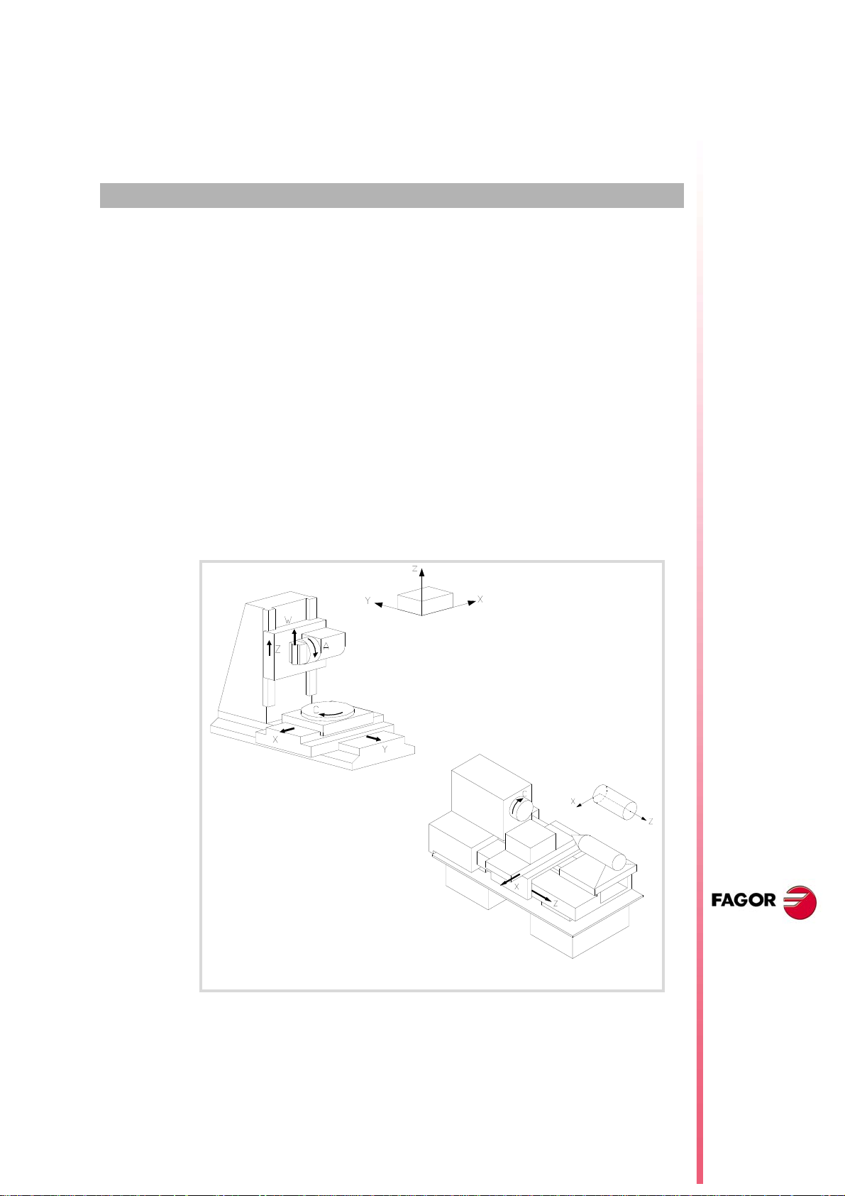
MACHINE OVERVIEW
2.1 Axis nomenclature
With this CNC, the manufacturer may select up to 28 axes (that must be properly defined
as linear, rotary, etc. by setting machine parameters), without no limitation as how to program
them and they may all be interpolated at the same time.
The DIN 66217 standard denomination for the axes is:
X-Y-Z Main axes of the machine. The X-Y axes form the main work plane whereas the
Z axis is parallel to the main axis of the machine and perpendicular to the XY
plane.
U-V-W Auxiliary axes, parallel to X-Y-Z respectively.
A-B-C Rotary axes, on X-Y-Z respectively.
However, the machine manufacturer may call the axes differently.
2
As an option, the name of the axes may be followed by a number between 1 and 9 (X1, X3,
Y5, A8...).
Axis nomenclature on different machines.
CNC 8070
(REF. 1309)
·57·
Page 58

2.
Programming manual
Right-hand rule
The direction of the X-Y-Z axes can easily be remembered using the right-hand rule (see
the drawing below).
On rotary axes, the positive turning direction is determined by the direction pointed by your
fingers when holding the rotary axis with your hand while your thumb points in the positive
direction of the linear axis.
Axis nomenclature
MACHINE OVERVIEW
CNC 8070
(REF. 1309)
·58·
Page 59

Programming manual
P (X,Y,Z)
(1,2,5)
(3,4,0)
(5,7,-2)
2.2 Coordinate system
Since one of the CNC's purposes is to control the movement and positioning of the axes,
a coordinate system is required that permits defining the position of the various target
(destination) points in the plane (2D) or in space (3D).
The main coordinate system is formed by the X-Y-Z axes. These axes are perpendicular to
each other and they meet at the origin point used as reference for the various points.
2.
Coordinate system
MACHINE OVERVIEW
The position of a point "P" in the plane or in space is defined by its coordinates on the various
axes.
Other types of axes such as auxiliary and rotary axes may also be part of the coordinate
system.
CNC 8070
(REF. 1309)
·59·
Page 60

2.
Example of the various coordinate systems on a milling machines.
XM YM ZM Machine reference system.
XF YF ZF Fixture reference system.
XW YW ZW Part reference system (datum point).
Programming manual
2.3 Reference systems
A machine may use the following reference systems.
• Machine reference system.
It is the coordinate system of the machine and it is set by the manufacturer of the machine.
• Fixture reference system.
It establishes a coordinate system associated with the fixtures being used. It is activated
by program and may be set by the operator in any position of the machine.
When the machine has several fixtures, each one may have its own reference system
associated with it.
• Part reference system (datum point).
It establishes a coordinate system associated with the part being machined. It is activated
by program and may be set by the operator anywhere on the part.
Reference systems
MACHINE OVERVIEW
CNC 8070
(REF. 1309)
·60·
Page 61

Programming manual
2.3.1 Origins of the reference systems
The position of the different reference systems is determined by their respective origin points.
O
M
Machine zero
It is the origin point of the machine reference system, set by the machine manufacturer.
O
F
Fixture zero
It is the origin point of the fixture reference system being used. Its position is defined by the
operator by using the "fixture offset" and is referred to machine zero.
The "fixture offset" may be set by program or from the CNC's front panel, as described in
the Operating Manual.
O
W
Part zero
It is the origin point of the reference system of the part (workpiece). Its position is set by the
operator using the "zero offset" and is referred:
• To the fixture offset, if the fixture reference system is active. When changing the fixture
reference system, the CNC updates the part zero position by referring to the new fixture
zero point.
• To the machine zero point (home), if the fixture reference system is NOT active. When
activating the fixture reference system, the CNC updates the part zero position by
referring it to the fixture zero point.
The "zero offset" may be set from the program or from the CNC front panel as described in
the Operating Manual.
2.
Reference systems
MACHINE OVERVIEW
Zero offset when:
(A)The fixture reference system is activated.
(B)The fixture reference system is deactivated.
CNC 8070
(REF. 1309)
·61·
Page 62

2.
Z
X
O
M
O
W
X
MH
X
MW
Z
MW
Z
MH
H
X
Z
H
O
M
O
W
Z
MH
Z
MW
X
MH
i
2.4 Home search
2.4.1 Definition of "Home search"
Home search
MACHINE OVERVIEW
Programming manual
It is the operation used to synchronize the system. This operation must be carried out when
the CNC loses the position of the origin point (e.g. by turning the machine off).
In order to perform the "Home search", the machine manufacturer has set particular points
of the machine; the machine zero and the machine reference point.
• Machine zero (home).
It is the origin point of the machine reference system.
• Machine reference point.
It is the physical point where the system is synchronized (except when the machine uses
distance-coded reference marks or absolute feedback). It may be located anywhere
I
0
on the machine.
When "searching home", the axes move to the machine reference point and the CNC
assumes the coordinate values assigned to that point by the machine manufacturer, referred
to machine zero. When using I
distance-coded reference marks or absolute feedback, the
0
axes will only move the distance necessary to verify their position.
CNC 8070
(REF. 1309)
O
M
O
W
H
X
MH YMH ZMH
XWH YWH Z
When programming a "Home search", neither the fixture offsets nor the zero offsets are canceled;
therefore, the coordinates are displayed in the active reference system.
On the other hand, if "Home search" is carried out one axis at a time in JOG mode (not in MDI), the
active offsets are canceled and the coordinates being displayed are referred to machine zero.
Machine zero (home).
Part zero.
Machine reference point.
Coordinates referred to machine reference system.
Coordinates referred to the part reference system.
WH
·62·
Page 63

Programming manual
G74 X1 Y2
G74 X2 Z1 A3
G74 Z1 Y2 X3 U2
G74 X1=1 X2=2
G74 X1=2 X2=1 A4 Z1=3
2.4.2 "Home search" programming
When programming a "Home search", the axes are homed sequentially in the order set by
the operator. All the axes need not be included in the "Home search", only those being
homed.
The "Home search" is programmed using the G74 function followed by the axes to be homed
and the number indicating their homing order. If the same order number is assigned to several
axes, those axes start homing at the same time and the CNC waits for all of them to end before
homing the next one.
When having numbered axes, they may be defined together with the other ones by assigning
them the order number as follows.
2.
Home search
MACHINE OVERVIEW
Spindle home search
The spindle home search is always carried out together with the first axis regardless of the
order in which it has been defined.
Home search and loop status.
Axes usually work in closed loop, although rotary axes can also work in open loop so they
can be controlled as if they were spindles.
The home search is carried out with the axes and spindles controlled in position; i.e. in closed
position loop. The CNC will close the position loop automatically on all axes and spindles
for which a home search has been programmed using function G74.
Using an associated subroutine
If the machine manufacturer has associated a home-search subroutine to the G74 function,
this function may be programmed alone in the block and the CNC will automatically execute
the associated subroutine [G.M.P. "REFPSUB (G74)"].
When using a subroutine, the "Home search" is carried out exactly as described earlier.
CNC 8070
(REF. 1309)
·63·
Page 64

2.
Programming manual
Home search
MACHINE OVERVIEW
CNC 8070
(REF. 1309)
·64·
Page 65

COORDINATE SYSTEM
3.1 Programming in millimeters (G71) or in inches (G70)
The displacements and feedrates of the axes may be defined in millimeters or in inches. The
unit system may be selected by program using the following functions:
G70 Programming in inches.
G71 Programming in millimeters.
Both functions may be programmed anywhere in the program; they do not have to go alone
in the block.
Operation
After executing one of these functions, the CNC assumes that unit system for the following
blocks. If none of these functions is programmed, the CNC uses the unit system set by
machine manufacturer [G.M.P. "INCHES"].
3
When changing the unit system, the CNC converts the currently active feedrate into the new
unit system.
...
G01 G71 X100 Y100 F508 (Programming in millimeters.)
(Feedrate: 508 mm/minute)
...
G70 (It changes the units.)
(Feedrate: 20 inches/minute)
...
Properties of the functions
Functions G70 and G71 are modal and incompatible with each other.
On power-up, after an M02 or M30 and after an EMERGENCY or a RESET, the CNC
assumes function G70 or G71 as set by the machine manufacturer [G.M.P. "INCHES"].
CNC 8070
(REF. 1309)
·65·
Page 66
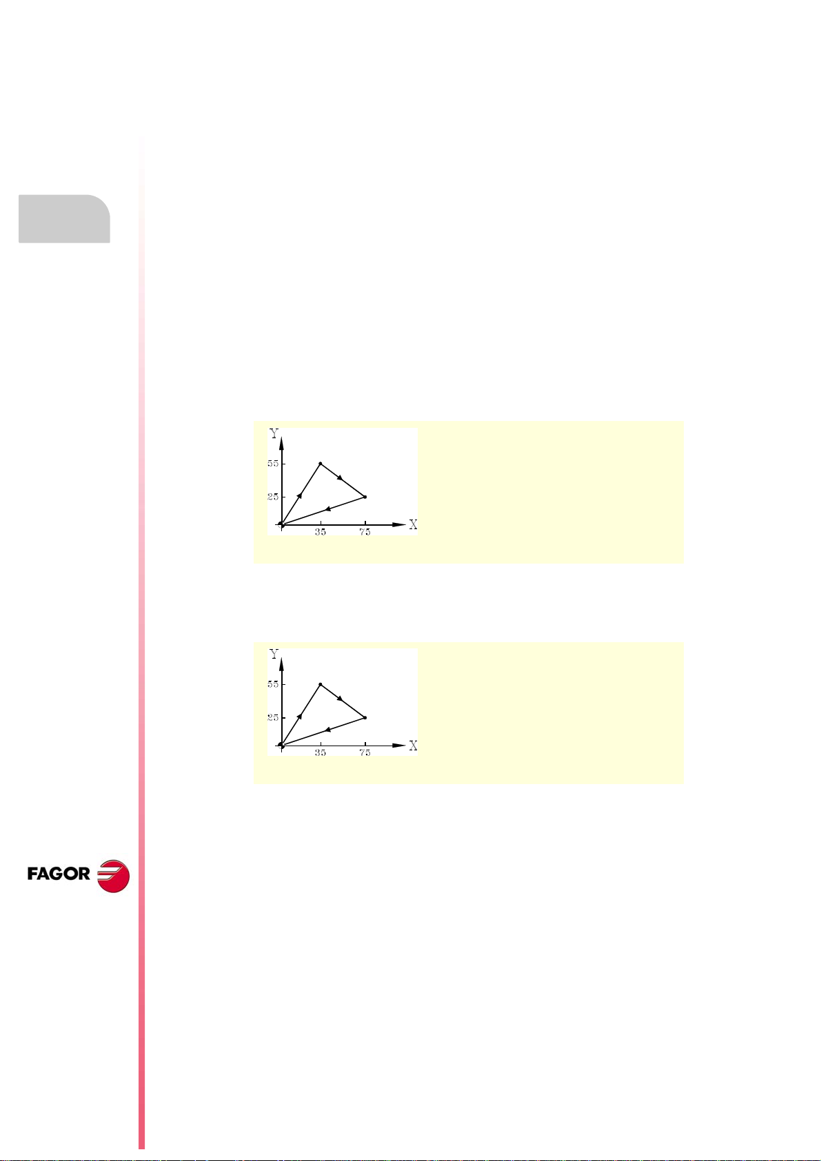
3.
3.2 Absolute (G90) or incremental (G91) coordinates
COORDINATE SYSTEM
Programming manual
The coordinates of the various points may be defined in absolute coordinates (referred to
the active origin point) or incremental coordinates (referred to the current position). The type
of coordinates may be selected by program using the following functions:
G90 Programming in absolute coordinates.
G91 Programming in incremental coordinates.
Both functions may be programmed anywhere in the program; they do not have to go alone
in the block.
Operation
After executing one of these functions, the CNC assumes that programming mode for the
following blocks. If none of these functions is programmed, the CNC uses the work mode
selected by machine manufacturer [G.M.P. "ISYSTEM"].
Depending on the active work mode (G90/G91), the coordinates of the points are defined
as follows:
• When programming in absolute coordinates (G90), the coordinates of the point are
referred to the current origin of the coordinate system, usually the part zero.
Absolute (G90) or incremental (G91) coordinates
N10 G00 G71 G90 X0 Y0
N20 G01 X35 Y55 F450
N30 X75 Y25
N40 X0 Y0
N50 M30
Programming in absolute coordinates.
• When programming in incremental coordinates (G91), the coordinates of the point are
referred to the current tool position. The preceding sign indicates the direction of the
movement.
N10 G00 G71 G90 X0 Y0
N20 G01 G91 X35 Y55 F450
N30 X40 Y-30
N40 X-75 Y-25
N50 M30
Programming in incremental coordinates.
Properties of the function
CNC 8070
(REF. 1309)
·66·
Functions G90 and G91 are modal and incompatible with each other.
On power-up, after an M02 or M30 and after an EMERGENCY or a RESET, the CNC
assumes function G90 or G91 as set by the machine manufacturer [G.M.P. "ISYSTEM"].
Page 67
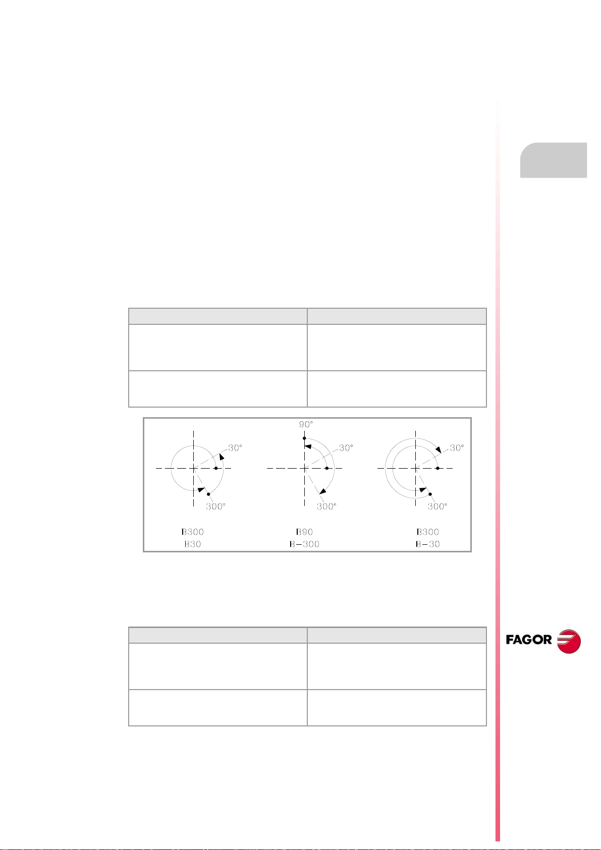
Programming manual
3.2.1 Rotary axes.
The CNC admits different ways to configure a rotary axis depending on how it is going to
move. Hence, the CNC can have rotary axes with travel limits, for example between 0º and
180º (linearlike rotary axis); axes that always move in the same direction (unidirectional
rotary axis); axes that choose the shortest path (positioning-only rotary axis).
All rotary axes must be programmed in degrees; therefore, they will not be affected by the
mm-inch conversion. The number of revolutions the axis will turn when programming a
distance greater than the module depends on the type of axis. The limits to display the
position values (coordinates) also depend on the type of axis.
Linearlike rotary axis.
The axis behaves like a linear axis, but it is programmed in degrees. The CNC displays the
position values between the travel limits.
Normal rotary axis.
This type of rotary axis can turn in both directions. The CNC displays the position values
between the limits of the module.
G90 movements. G91 movements.
The sign of the position value indicates the
moving direction; the absolute position value
indicates the target position.
Even if the programmed distance is greater than
the module, the axis never turns more than one
revolution.
Normal incremental movement. The sign of the
position value indicates the moving direction; the
absolute position value indicates the position
increment.
If the programmed distance is greater than the
module, the axis turns more than one revolution.
3.
COORDINATE SYSTEM
Absolute (G90) or incremental (G91) coordinates
Unidirectional rotary axis.
This type of rotary axis only moves in one direction, the one that has been preset for it. The
CNC displays the position values between the limits of the module.
G90 movements. G91 movements.
The axis moves in the preset direction up to the
programmed position.
Even if the programmed distance is greater than
the module, the axis never turns more than one
revolution.
The axis only admits movements in the preset
direction. The sign of the position value indicates
the moving direction; the absolute position value
indicates the position increment.
If the programmed distance is greater than the
module, the axis turns more than one revolution.
CNC 8070
(REF. 1309)
·67·
Page 68
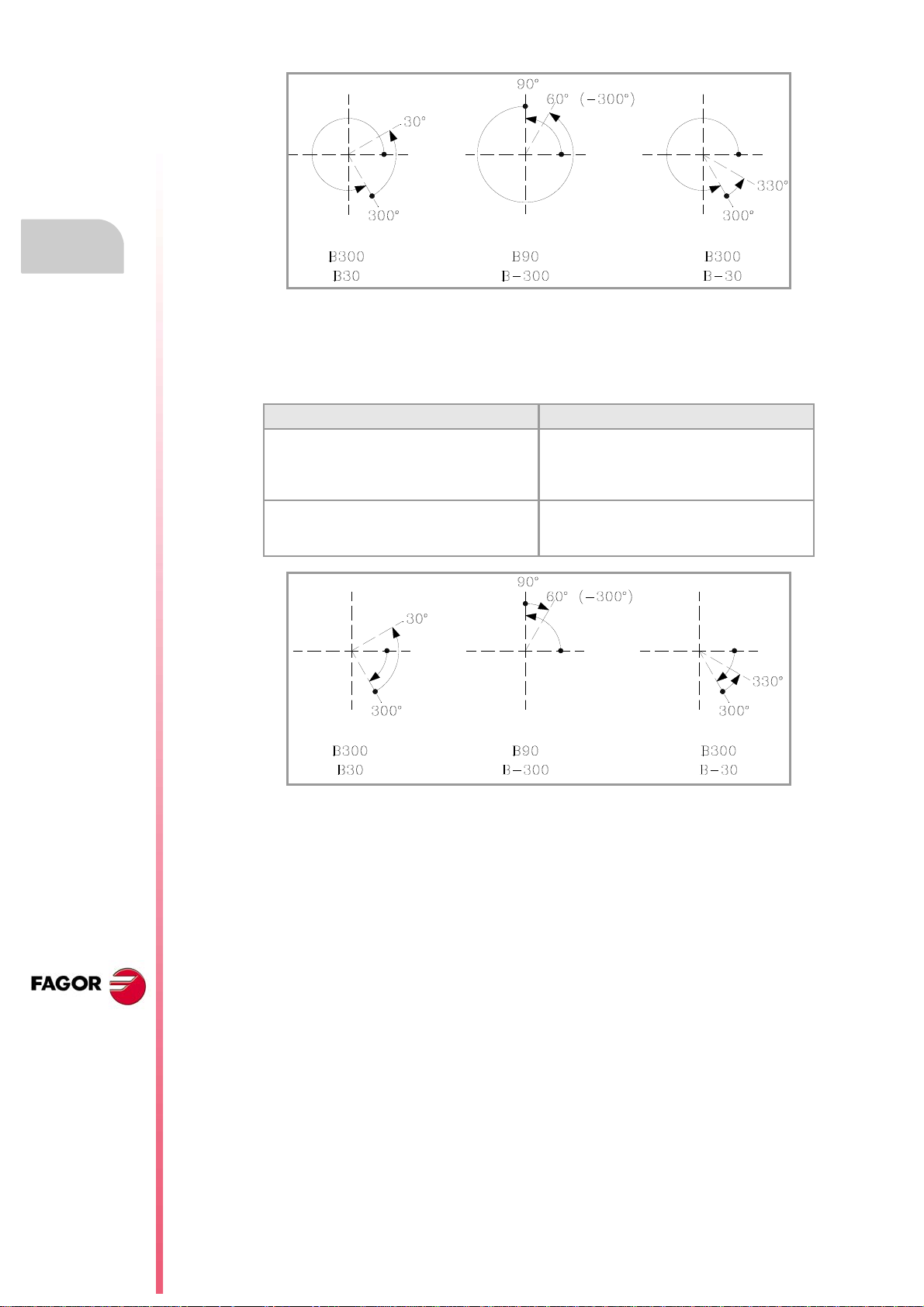
3.
COORDINATE SYSTEM
Programming manual
Positioning-only rotary axis.
This type of rotary axis can move in both directions; but in absolute movements, it only moves
via the shortest path. The CNC displays the position values between the limits of the module.
G90 movements. G91 movements.
The axis moves via the shortest path up to the
programmed position.
Even if the programmed distance is greater than
the module, the axis never turns more than one
revolution.
Normal incremental movement. The sign of the
position value indicates the moving direction; the
absolute position value indicates the position
increment.
If the programmed distance is greater than the
module, the axis turns more than one revolution.
Absolute (G90) or incremental (G91) coordinates
CNC 8070
(REF. 1309)
·68·
Page 69
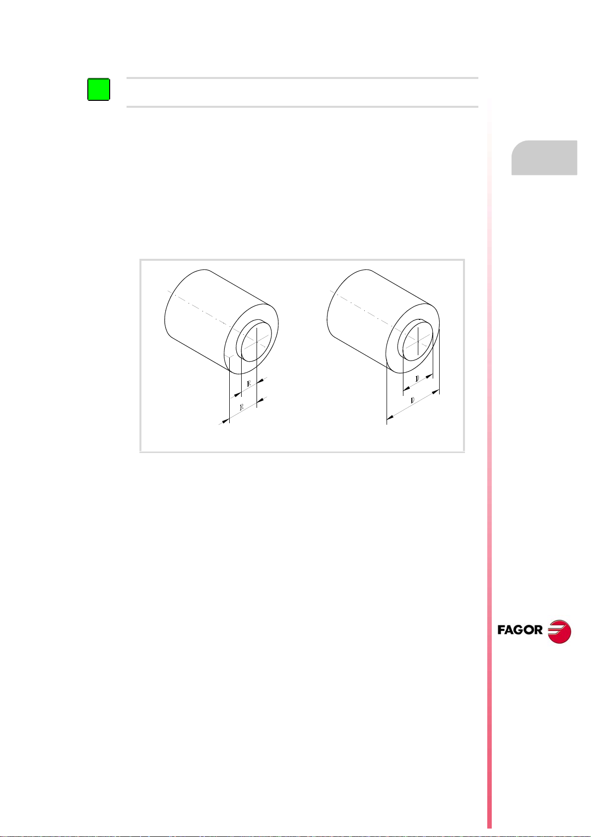
Programming manual
i
3.3 Programming in radius (G152) or in diameters (G151)
The following functions are oriented to lathe type machines. Programming in diameters is only available
on the axes allowed by the machine manufacturer (DIAMPROG=YES).
Programming in radius or diameters may be selected by program with these functions:
G151 Programming in diameters.
G152 Programming in radius.
These functions may be programmed anywhere in the program and they don't have to go
alone in the block.
Operation
After executing one of these functions, the CNC assumes that programming mode for the
following blocks.
3.
COORDINATE SYSTEM
Programming in radius. Programming in diameters.
When switching programming modes, the CNC changes the way it displays the coordinates
of the corresponding axes.
Properties of the function
Functions G151 and G152 are modal and incompatible with each other.
On power-up, after executing an M02 or M30, and after an EMERGENCY or RESET, the CNC
assumes function G151 if machine parameter DIAMPROG of any of the axes is set to YES.
Programming in radius (G152) or in diameters (G151)
CNC 8070
(REF. 1309)
·69·
Page 70
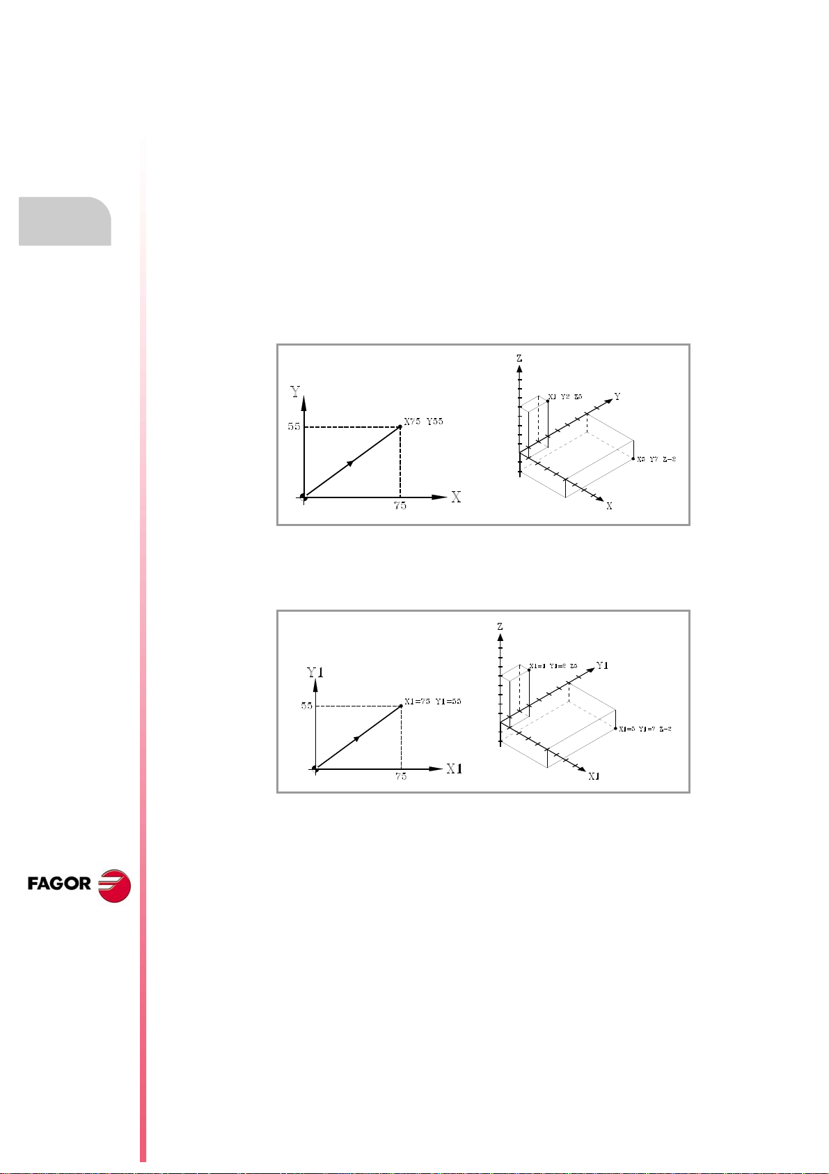
3.
3.4 Coordinate programming
3.4.1 Cartesian coordinates
Coordinate programming
COORDINATE SYSTEM
Programming manual
Coordinates are programmed according to a Cartesian coordinate system. This system
consists of two axes in the plane and three or more in space.
Definition of position values
The position of a point in this system is given by its coordinates in the different axes. The
coordinates are programmed in absolute or incremental coordinates and in millimeters or
inches.
Standard axes (X...C)
The coordinates are programmed with the axis name followed by the coordinate value.
CNC 8070
Numbered axes (X1...C9)
If the axis name is like X1, Y2... the "=" sign must be included between the axis name and
the coordinate.
(REF. 1309)
·70·
Page 71
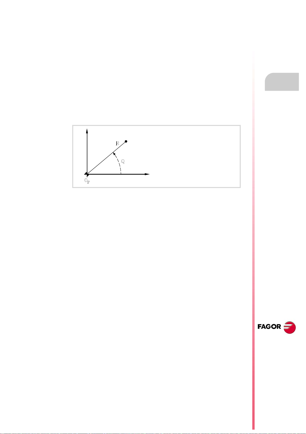
Programming manual
3.4.2 Polar coordinates
When having circular elements or angular dimensions, polar coordinates may be more
convenient to express the coordinates of the various points in the plane.
This type of coordinates requires a reference point referred to as "polar origin" that will be
the origin of the polar coordinate system.
Definition of position values
The position of the various points is given by defining the radius "R" and the angle "Q" as
follows:
Radius It will be the distance between the polar origin and the point.
Angle It will be the one formed by the abscissa axis and the line joining the polar
3.
origin with the point.
R Radius
Q Angle
OP Polar origin
The radius may be given in mm or in inches whereas the angle is given in degrees.
Both values may be given in either absolute (G90) or incremental (G91) coordinates.
• When working in G90, the "R" and "Q" values will be absolute. The value assigned to
the radius must always be positive or zero.
• When working in G91, the "R" and "Q" values will be incremental. Although negative "R"
values may be programmed, when programming in incremental coordinates, the
resulting value assigned to the radius must always be positive or zero.
When programming a "Q" value greater than 360º, the module will be assumed after dividing
it by 360. Thus, Q420 is the same as Q60 and Q-420 is the same as Q-60.
Polar origin preset
The "polar origin" may be selected from the program using function G30. If not selected, it
assumes as "polar origin" the origin of the active reference system (part zero). See chapter
"5 Origin selection".
Coordinate programming
COORDINATE SYSTEM
The selected "polar origin" is modified in the following instances:
• When changing the work plane, the CNC assumes the part zero as the new "polar origin".
• On power-up, after an M02 or M30 and after an EMERGENCY or a RESET, the CNC
assumes the part zero as the new polar origin.
CNC 8070
(REF. 1309)
·71·
Page 72
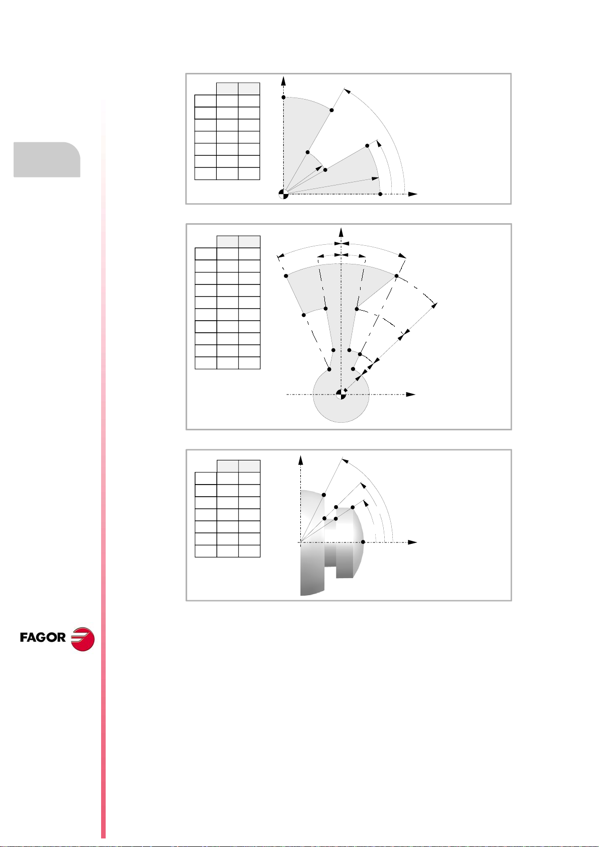
3.
P1
P2
P3
P4
P5
P6
50
30
o
60
o
P0
Y
X
RQ
P0 0
P1 10000
P2
P3
P4
100
50
50
30
30
60
P5 100 60
P6 100 90
10
6
10
10
25
25
15
15
P1
P2
P3
P4
P5
P6
P7
P8
P9
P10
Ow
R
P1 46
P2
P3
P4
31
16
16
P5 10
P6 10
P7 16
P8
P9
P10
31
31
46
Q
65
80
80
65
65
115
100
100
115
115
Y
X
P0
P1
P2
P3
P4
P5
P6
63.4
o
45
o
33.7
o
RQ
P0 430
P1 430033.7
P2
P3
P4
340
290
230
45
33.7
45
P5 360 63.4
P6 360 90
X
Z
Coordinate programming
COORDINATE SYSTEM
Programming manual
Examples. Point definition in polar coordinates.
CNC 8070
(REF. 1309)
·72·
Page 73

WORK PLANES.
The work planes determine which axes define the work plane/trihedron and which axis
corresponds to the longitudinal axis of the tool. Plane selection is required to execute
operations like:
• Circular and helical interpolations.
• Corner chamfering and rounding.
• Tangential entries and exits.
• Machining canned cycles.
• Tool radius and length compensation.
These operations, except tool length compensation, can only be executed in the active work
plane. Tool length compensation, on the other hand, can only be applied on the longitudinal
axis.
4
Commands for changing the work planes.
Mill model or lathe model with "trihedron" type axis configuration.
Function. Meaning.
G17 Main plane formed by the first axis (abscissa), second (ordinate) and third axis
(perpendicular) of the channel.
G18 Main plane formed by the third axis (abscissa), first axis (ordinate) and second axis
(perpendicular) of the channel.
G19 Main plane formed by the second axis (abscissa), third axis (ordinate) and first axis
(perpendicular) of the channel.
G20 Select any work plane formed by the first three axes of the channel.
Instruction. Meaning.
#TOOL AX Select the longitudinal axis of the tool.
Lathe model with "plane" type axis configuration.
Function. Meaning.
G18 Main plane formed by the second axis (abscissa) and first axis (ordinate) of the
channel.
G20 Select the longitudinal axis of the tool.
Instruction. Meaning.
#TOOL AX Select the longitudinal axis of the tool.
CNC 8070
(REF. 1309)
·73·
Page 74

4.
X+
Z+
X+
Z+
Y+
Programming manual
4.1 About work planes on lathe and mill models.
The operation of the work planes depends on the geometric configuration of the axes. At a
mill model, the geometric configuration of the axes is always of the "trihedron" type whereas
at a lathe model, the geometric configuration of the axes may be either a "trihedron" type
or a "plane" type (parameter GEOCONFIG).
WORK PLANES.
Configuration of "plane" type axes. Configuration of "Trihedron" type axes.
Configuration of "Trihedron" type axes (lathe or mill model).
About work planes on lathe and mill models.
This configuration has three axes forming a trihedron Cartesian XYZ type . There may be
more axes, besides those forming the trihedron; that may be part of the thihedron or be
auxiliary axes, rotary axes, etc.
The order of the axes in the channel sets the main work planes, those selected with functions
G17, G18 and G19. Function G20 may be used to form any work plane with the first three
axes of the channel. The work plane by default is set by the manufacturer (parameter
IPLANE), the usual plane being G17 at a mill model and G18 at a lathe model.
The CNC displays the ·G· functions associated with the work planes.
Configuration of "plane" type axes (lathe model).
This configuration has two axes forming the usual work plane on a lathe. There may be more
axes, but they cannot be part of the trihedron; there must be auxiliary, rotary, etc.
With this configuration, the work plane is always G18 and will be formed by the first two axes
defined in the channel, the second axis as abscissa and the first axis as ordinate. The ·G·
functions associated with the work planes have the following effects.
Function. Meaning.
G17 It does not change planes and shows a warning about it.
G18 It has no effect (except when function G20 is active).
G19 It does not change planes and shows a warning about it.
G20 It is permitted if it does not change the main plane; i.e. it can only be used to change
the longitudinal axis.
CNC 8070
(REF. 1309)
·74·
The CNC does not display the ·G· functions associated with the work planes because it is
always the same plane.
Page 75

Programming manual
4.2 Select the main new work planes.
4.2.1 Mill model or lathe model with "trihedron" type axis configuration.
The main planes may be selected by program using functions G17, G18 and G19 and are
formed by two of the first three axes of the channel. Ther third axis corresponds to the axis
perpendicular to the plane, which coincides with the longitudinal axis of the tool, the one on
which tool length compensation is applied.
G17 Main plane formed by the first axis (abscissa), second (ordinate) and third axis
(perpendicular) of the channel.
G18 Main plane formed by the third axis (abscissa), first axis (ordinate) and second
axis (perpendicular) of the channel.
G19 Main plane formed by the second axis (abscissa), third axis (ordinate) and first
axis (perpendicular) of the channel.
The OEM, can use machine parameter LCOMPTYP to change the behavior of the
longitudinal axis when changing planes so the CNC keeps the longitudinal axis that was
active before changing planes.
Function G20 may select any plane with the first three axes of the channel. Function G20
and the instruction #TOOL AX can change the longitudinal axis of the tool.
4.
WORK PLANES.
Programming.
These functions may be programmed anywhere in the program and they don't have to go
alone in the block.
Programming format.
The programming format is:
G17
G18
G19
G17
G18
G19
Properties of the function and Influence of the reset, turning the
CNC off and of the M30 function.
Functions G17, G18, G19 and G20 are modal and incompatible with each other. On powerup, after an M02 or M30 and after an emergency or a reset, the CNC assumes function G17
or G18 as set by the machine manufacturer (parameter "IPLANE").
Select the main new work planes.
CNC 8070
(REF. 1309)
·75·
Page 76

4.2.2 Lathe model with "plane" type axis configuration.
The work plane is always G18 and will be formed by the first two axes defined in the channel.
Functions G17 and G19 have no meaning for the CNC.
G18 Main plane formed by the second axis (abscissa) and first axis (ordinate) of the
channel.
In the case of lathe tools, tool length compensation is applied on all the axes where a tool
offset has been defined.
Programming manual
4.
WORK PLANES.
Select the main new work planes.
On milling tools, tool length compensation is applied on the second axis of the channel. If
the X (first axis of the channel) and Z (second axis of the channel) axes have been defined,
the work plane will be the ZX and Z will be the longitudinal axis. Function G20 and the
instruction #TOOL AX can change the longitudinal axis of the tool.
Programming.
These functions may be programmed anywhere in the program and they don't have to go
alone in the block.
Programming format.
The programming format is:
G18
G18
Properties of the function and Influence of the reset, turning the
CNC off and of the M30 function.
Functions G18 and G20 are modal and incompatible with each other. On power-up, after
executing an M02 or M30, and after an emergency or reset, the CNC assumes function G18.
CNC 8070
(REF. 1309)
·76·
Page 77

Programming manual
4.3 Select any work plane and longitudinal axis.
The meaning of function G20 depends on the type of configuration of the machines axes;
"plane" type for lathe or "trihedron" type for lathe or mill.
• When the axis configuration is of trihedron type, function G20 allows defining any work
plane formed by the first three axes of the channel. To build a plane with other axes, first
include them in the main trihedron (instruction #SET AX).
• When the axis configuration is of plane type, the work plane is always G18 and function
G20 allows changing the longitudinal axis of the tool.
Programming.
When programming this instruction, you must define the new abscissa and ordinate axes
of the plane and the longitudinal axis of the tool. If the longitudinal axis coincides with one
of the axes of the plane, you must also define which axis is perpendicular to the plane.
4.
Programming format.
The programming format is the following; the list of arguments appears between curly
brackets and the optional ones between angle brackets.
G20 X~C{axistype} X~C{axistype} X~C{axistype} <X~C{axistype}>
{axistype}
Values for setting the location of the axis in the plane.
The work plane is defined by selecting the abscissa and ordinate axes, the perpendicular
axis and the longitudinal axis of the tool. It is selected by assigning one of the following values
to the axes programmed with G20.
Val ue. Type of axis within the work plane.
1 Abscissa axis.
2 Ordinate axis.
±3 Longitudinal axis of the tool. The sign indicates tool orientation.
4 Reserved.
5 Axis perpendicular to the work plane, only required when the longitudinal axis of the tool
G20 X1 Z2 Y3
The X axis is the abscissa axis.
The Z axis is the ordinate axis.
The Y axis is the longitudinal axis of the tool and the axis
perpendicular to the plane.
Value that sets the location of the axis in the plane.
is the same as the abscissa or ordinate axis. Otherwise, the longitudinal axis of the tool
will be the perpendicular axis.
WORK PLANES.
Select any work plane and longitudinal axis.
G20 X1 Y2 X3 Z5
The X axis is the abscissa axis and the longitudinal axis of the
tool.
The Y axis is the ordinate axis.
The Z axis is the axis perpendicular to the plane.
CNC 8070
(REF. 1309)
·77·
Page 78

4.
Programming manual
Select the longitudinal axis of the tool.
When selecting the longitudinal axis with G20, tool orientation may be established according
to the programmed sign.
• If the parameter to select the longitudinal axis is positive, the tool is positioned in the
positive direction of the axis.
• If the parameter to select the longitudinal axis is negative, the tool is positioned in the
negative direction of the axis.
WORK PLANES.
Select any work plane and longitudinal axis.
G20 X1 Y2 Z3 G20 X1 Y2 Z-3 G20 X1 Y2 X-3 Z5
Properties of the function and Influence of the reset, turning the
CNC off and of the M30 function.
Function G20 is modal and incompatible with G17, G18 and G19. On power-up, after an M02
or M30 and after an emergency or a reset, the CNC assumes function G17 or G18 as set
by the machine manufacturer (parameter "IPLANE").
CNC 8070
(REF. 1309)
·78·
Page 79

Programming manual
4.4 Select the longitudinal axis of the tool.
The instruction #TOOL AX allows changing the longitudinal axis of the tool except on those
for turning. This instruction allows to select any machine axis as the new longitudinal axis.
Programming.
When programming this instruction, you must define the new axis and the orientation of the
tool.
Programming format.
The programming format is the following; the list of arguments appears between curly
brackets.
#TOOL AX [X~C{+|-}]
{+|-}
#TOOL AX [Z+]
#TOOL AX [V2-]
Define the orientation of the tool.
Tool orientation.
4.
WORK PLANES.
Tool orientation is set as follows.
+ sign
- sign
Positive tool orientation.
#TOOL AX [X+]
#TOOL AX [Y+]
#TOOL AX [Z+]
Negative tool orientation.
#TOOL AX [X-]
#TOOL AX [Y-]
#TOOL AX [Z-]
Positive tool orientation.
Negative tool orientation.
Select the longitudinal axis of the tool.
CNC 8070
(REF. 1309)
·79·
Page 80

4.
Programming manual
WORK PLANES.
Select the longitudinal axis of the tool.
CNC 8070
(REF. 1309)
·80·
Page 81
ORIGIN SELECTION
With this CNC, it is possible to program movements in the machine reference system or apply
offsets in order to use reference systems referred to the fixtures or the part without having
to change the coordinates of the different points of the part in the program.
There are three different offset types; fixture offset, zero offsets and PLC offsets. The CNC
may have several of these offsets active at the same time, in that case, the system coordinate
origin being used will be defined by the sum of the active offsets.
Type of offset. Description.
Fixture offset. Distance between the machine reference zero and the fixture's
Zero offset. Distance between the fixture's zero point and the part zero. If the
PLC offset. Special offset handled by the PLC that is used to correct the
5
zero point.
On machines using several fixtures, this offsets allows selecting
the particular fixture to be used.
fixture zero is not active (no fixture offset), the zero offset is
measured from machine zero.
The zero offset may be set by presetting a coordinate or a zero
offset.
deviations due to dilatations, etc.
The PLC always applies this offset, even when programming
with respect to machine zero.
CNC 8070
(REF. 1309)
·81·
Page 82

5.
ORIGIN SELECTION
Programming manual
5.1 Programming with respect to machine zero
Machine zero is the origin of the machine reference system. Movements referred to machine
zero are programmed using the instructions #MCS and #MCS ON/OFF.
Program a movement referred to machine zero.
This instruction may be added to any block containing a movement so it is executed in the
machine reference system.
G00 X30 Y30
G92 X0 Y0 (Coordinate preset)
G01 X20 Y20
#MCS X30 Y30 (Movement referred to machine zero. Offsets canceled)
G01 X40 Y40 (Offsets restored)
G01 X60 Y60
M30
Machine coordinate system.
The #MCS ON and #MCS OFF instructions activate and deactivate the machine reference
system; therefore, the movements programmed between them are executed in the machine
Programming with respect to machine zero
reference system. Both instructions must be programmed alone in the block.
G92 X0 Y0 (Coordinate preset)
G01 X50 Y50
#MCS ON (Beginning of programming referred to machine zero)
G01 ...
G02 ...
G00 ...
#MCS OFF (End of programming referred to machine zero. Offsets restored)
Considerations for movements referred to machine zero.
Zero offsets and coordinate transformations
When executing a movement referred to machine zero, the CNC ignores the active offsets
(except the PLC offset), the kinematics and cartesian transformations; therefore, the
movement is carried out in the machine reference system. Once the movement has ended,
the CNC restores the offsets, kinematics and cartesian transformations that were active.
The programmed movements do not admit polar coordinates, nor other kinds of
transformations such as mirror image, coordinate (pattern) rotation or scaling factor. While
the #MCS function is active, functions for setting a new origin such as G92, G54-G59, G158,
G30, etc. are not admitted either.
CNC 8070
(REF. 1309)
·82·
Tool radius and length compensation
Tool radius and length compensation is also canceled during the movements referred to
machine zero. The CNC assumes that the coordinates have been programmed with respect
to the tool base, not to the tool tip.
Page 83

Programming manual
System units; millimeters or inches
When moving with respect to machine reference zero, the G70 or G71 units
(inches/millimeters) selected by the user are ignored. It assumes the units predefined at the
CNC (INCHES parameter); assumed by the CNC on power-up. These units are assumed
for defining the coordinates, for the feedrate and for the speed.
5.
ORIGIN SELECTION
Programming with respect to machine zero
CNC 8070
(REF. 1309)
·83·
Page 84

5.2 Set the machine coordinate (G174).
i
Use this function with caution. Changing the machine coordinate can cause the axes to exceed the
travel limits during the movement.
Function G174 may be used to set the machine coordinate of an axis or spindle; in other
words, temporarily set a new machine zero. The new machine coordinate stays active until
the axis or spindle is homed; then, the CNC restores the original machine reference zero
(set in the machine parameters).
Programming manual
5.
ORIGIN SELECTION
Set the machine coordinate (G174).
After executing function G174, the CNC assumes that the programmed coordinate defines
the current position referred to machine reference zero (home). The zero offsets, movements
with respect to machine zero, etc. will be referred to the coordinate programmed in G174.
Programming the function.
Program function G174, and then the machine coordinate of a single axis or spindle. With
this function only the machine coordinate of an axis or spindle may be set; to set the machine
coordinates of several, program one G174 for each one of them.
When setting the machine coordinate, the CNC ignores the G70/G71 units
(inches/millimeters) selected by the user and uses the unit system pre-defined at the CNC
(parameter INCHES). The CNC also ignores all the other options, radius/diameter, mirror
image, scaling factor, etc.
Programming format.
The programming format is:
G174 X..C
G174 S
X..C Machine coordinate at the axes.
S Machine coordinate at the spindles.
G174 X100
G174 S180
CNC 8070
(REF. 1309)
Considerations and limitations.
Function G174, by itself, does not cause any axis or spindle movement. After executing
function G174, the CNC considers that the axis or sp indle is homed and verifies that it is within
the software travel limits.
The CNC does not allow setting the machine coordinate on slaved axes, grantry, tandem or
on axes that are part of the active kinematics or active transform. The CNC permits setting
the machine coordinate for tandem axes. Before setting the new machine coordinate, the
CNC checks that the axis or spindle is in position and it is not synchronized, if that's not the
case, it issues an error message.
On Sercos axes, function G174 also resets the coordinate of the drive. Setting the machine coordinates
on position-Sercos axes requires drive version V6.20 or newer.
Properties of the function and Influence of the reset, turning the
CNC off and of the M30 function.
Function G174 is modal. This function is neither affected by functions M02 and M30 nor by
a reset, by an emergency or by turning the CNC off. On power-up, the CNC assumes the
machine coordinates that were active when the CNC was turned off.
·84·
Page 85
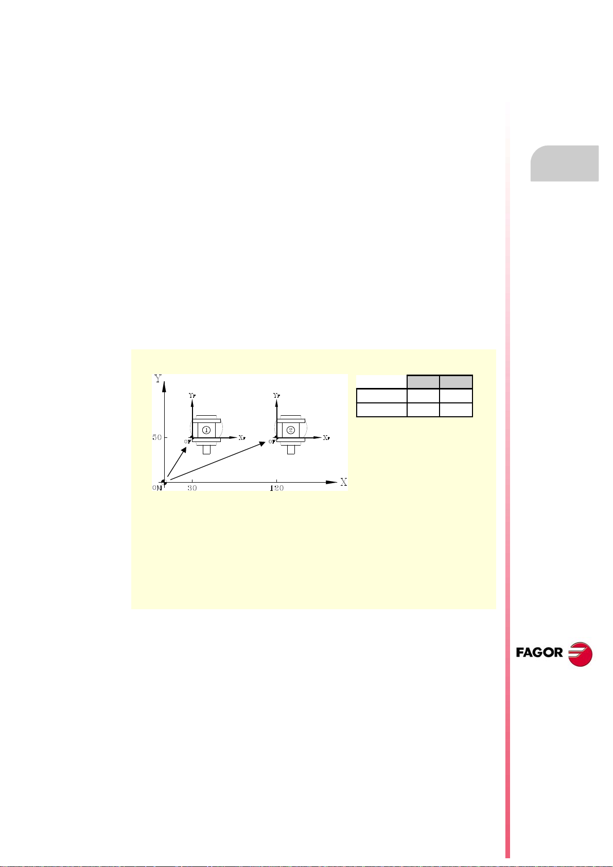
Programming manual
X Y
V.G.FIX=1
30 50
V.G.FIX=2
120 50
Fixture offset value on milling machine.
5.3 Fixture offset
With fixture offsets, it is possible to select the fixture system to be used (when having more
than one fixture). When applying a new fixture offset, the CNC assumes the point set by the
new selected fixture as the new fixture zero.
Defintion
In order to apply a fixture offset, it must have been previously set. To do that, the CNC has
a table where the operator may define up to 10 different fixture offsets. The table data may
be defined:
• Manually from the CNC's front panel (as described in the Operating Manual).
• By program, assigning the corresponding value (of the "n" offset and of the "Xn" axis)
to the "V.A.FIXT[n].Xn" variable.
5.
Fixture offset
Activation
Once the fixture offsets have been defined in the table, they may be activated via program
by assigning to the "V.G.FIX" variable, the offset number to be applied.
Only one fixture offset may be active at a time; therefore, when applying a fixture offset, it
will cancel the previous one. Assigning a value of "V.G.FIX=0" will cancel the active fixture
offset.
N100 V.A.FIXT[1].X=30 V.A.FIXT[1].Y=50
N110 V.A.FIXT[2].X=120 V.A.FIXT[2].Y=50
...
N200 V.G.FIX=1 (It applies the first fixture offset)
N210 ... (Programming at fixture 1)
N300 V.G.FIX=2 (It applies the first fixture offset)
N310 ... (Programming at fixture 2)
N400 V.G.FIX=0 (Cancel fixture offset. No fixture system is active)
ORIGIN SELECTION
Considerations
A fixture offset, by itself, does not cause any axis movement.
Properties
On power-up, the CNC assumes the fixture offset that was active when the CNC was turned
off. On the other hand, the fixture offset is neither affected by functions M02 and M30 nor
by RESETTING the CNC.
CNC 8070
(REF. 1309)
·85·
Page 86
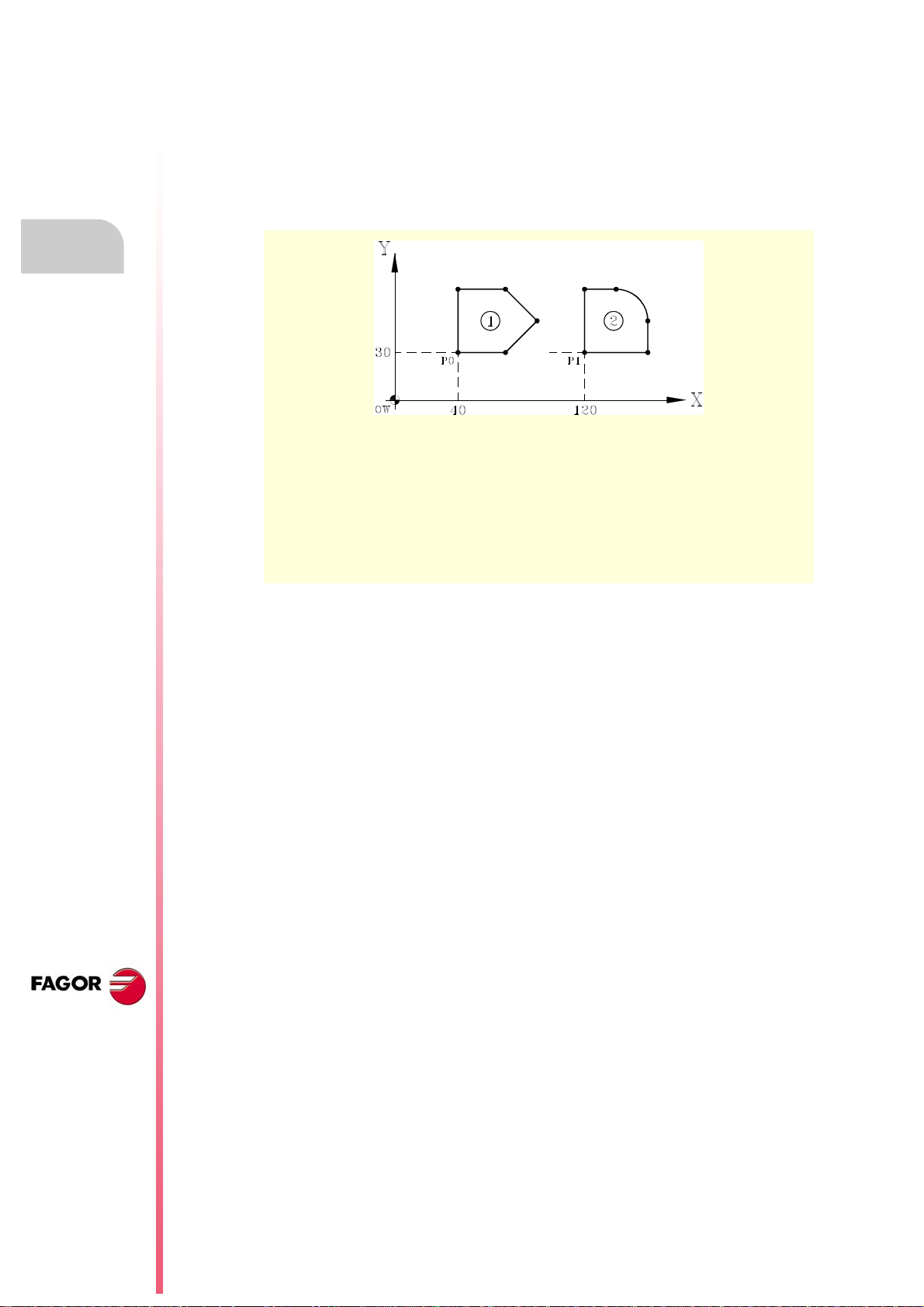
5.
Programming manual
5.4 Coordinate preset (G92)
Coordinate presetting is done with function G92 and it may be applied onto any axis of the
machine.
When presetting a coordinate, the CNC interprets that the axis coordinates programmed
after the G92 set the current position of the axes. The rest of the axes that have not been
defined with G92 are not affected by the preset.
ORIGIN SELECTION
Coordinate preset (G92)
N100 G90 G01 X40 Y30 (Positioning at P0)
N110 G92 X0 Y0 (Presetting P0 as part zero)
... (Machining of profile 1)
N200 G90 G01 X80 Y0 (Positioning at P1)
N210 G92 X0 Y0 (Presetting P1 as part zero)
... (Machining of profile 2)
N300 G92 X120 Y30 (Recovering OW as part zero)
CNC 8070
Considerations
A coordinate preset, by itself, does not cause any axis movement.
When homing an axis in JOG mode, the preset for that axis is canceled.
Properties of the function
G92 is modal, the preset values remain active until the preset is canceled (with another
preset, a zero offset or with G53).
On power-up, the CNC assumes the coordinate preset that was active when the CNC was
turned off. On the other hand, the coordinate preset is neither affected by functions M02 and
M30 nor by RESETTING the CNC.
(REF. 1309)
·86·
Page 87

Programming manual
Y
X
70
10
30
20
50
120
Ow
Ow
Ow
G54
G55
G56
P1
O
M
X Y
G54 (G159=1)
20 70
G55 (G159=2)
50 30
G56 (G159=3)
120 10
5.5 Zero offsets (G54-G59/G159)
Using zero offsets, it is possible to place the part zero in different positions of the machine.
When applying a zero offset, the CNC assumes as the new part zero the point defined by
the selected zero offset.
Defining zero offsets.
In order to apply a zero offset, it must have been previously defined. To do that, the CNC
has a table where the operator may define up to 99 different zero offsets. The table data may
be defined manually (as described in the operating manual) or via program (using variables).
The OEM may have configured the zero offset table in one of the following ways (machine
parameter FINEORG).
• Each zero offset has a single value. When executing function G159, the CNC assumes
this value as the new zero offset.
• Each zero offset has a coarse (or absolute) value and a fine (or incremental) value. When
executing function G159, the CNC assumes as new zero offset the sum of both parts.
5.
ORIGIN SELECTION
Activation
Once the zero offsets have been defined in the table, they may be activated via program by
programming function G59 followed by the offset number to be activated.
G159=2 The CNC applies the second zero offset.
G159=11 The CNC applies the 11th zero offset.
The first six zero offsets of the table can also be applied using functions G54 through G59;
G54 for the first one (same as G159=1), G55 for the second one (same as G159=2) and so on.
G54 The CNC applies the first zero offset (G159=1).
G59 The CNC applies the sixth zero offset (G159=6).
N100 V.A.ORGT[1].X=20 V.A.ORGT[1].Y=70
N110 V.A.ORGT[2].X=50 V.A.ORGT[2].Y=30
N100 V.A.ORGT[3].X=120 V.A.ORGT[3].Y=10
...
N100 G54
(It applies the first zero offset)
N200 G159=2
(It applies the second zero offset)
N300 G56 X20 Y30
(It applies the third zero offset)
(The axes move to point X20 Y30 (point P1) referred to the third origin)
Zero offsets (G54-G59/G159)
CNC 8070
(REF. 1309)
·87·
Page 88

5.
X Z
G54 (G159=1) 0 420
G55 (G159=2) 0 330
G56 (G159=3) 0 240
G57 (G159=4) 0 150
X
Z
90 9090
150 240 330
A2A3A4
90
A1
420
G54G55G56G57
Programming manual
ORIGIN SELECTION
Zero offsets (G54-G59/G159)
N100 V.A.ORGT[1].X=0 V.A.ORGT[1].Z=420
N110 V.A.ORGT[2].X=0 V.A.ORGT[2].Z=330
N100 V.A.ORGT[3].X=0 V.A.ORGT[3].Z=240
N100 V.A.ORGT[4].X=0 V.A.ORGT[3].Z=150
N100 G54 (It applies the first absolute zero offset)
··· (Machining of profile A1)
N200 G55 (It applies the second absolute zero offset)
··· (Machining of profile A2)
N300 G56 (It applies the third absolute zero offset)
··· (Machining of profile A3)
N200 G56 (It applies the fourth absolute zero offset)
··· (Machining of profile A4)
Only one zero offset may be active at a time; therefore, when applying a zero offset, the
previous one will be canceled. When programming G53, the zero offset currently active will
be canceled.
The function corresponding to the selected zero offset may be programmed in any block of
the program. When added to a block with path information, the zero offset will be applied
before executing the programmed movement.
Considerations
CNC 8070
(REF. 1309)
·88·
A zero offset, by itself, does not cause any axis movement.
When homing an axis in JOG mode, the absolute zero offset for that axis is canceled.
Properties of the functions
Functions G54, G55, G56, G57, G58, G59 and G159 are modal and incompatible with each
other and with G53 and G92.
On power-up, the CNC assumes the zero offset that was active when the CNC was turned
off. On the other hand, the zero offset is neither affected by functions M02 and M30 nor by
RESETTING the CNC.
Page 89
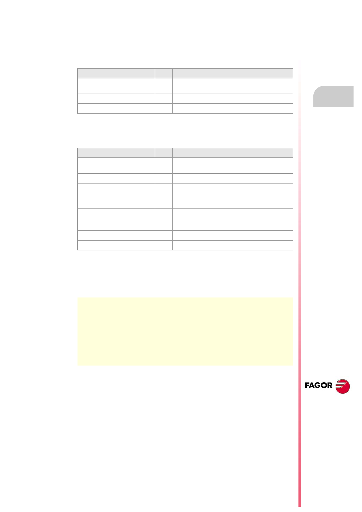
Programming manual
5.5.1 Variables for setting zero offsets
Zero offset table (without fine setting of the absolute zero offset).
The following variables may be accessed via part-program or via MDI/MDA mode. Each of
them indicates whether it may be read (R) or written (W).
Variable. R/W Meaning.
(V.)[ch].A.ORG.xn R Value of the active zero offset (absolute G159 +
(V.)[ch].A.ADDORG.xn R Value of the active incremental zero offset (G158).
(V.)[ch].A.ORGT[nb].xn R/W Offset set in the zero offset [nb].
Zero offset table (with fine setting of the absolute zero offset).
The following variables may be accessed via part-program or via MDI/MDA mode. Each of
them indicates whether it may be read (R) or written (W).
Variable. R/W Meaning.
(V.)[ch].A.ORG.xn R Value of the active zero offset (coarse absolute G159 +
(V.)[ch].A.ADDORG.xn R Value of the active incremental zero offset (G158).
(V.)[ch].A.COARSEORG.xn R Value of the active absolute zero offset (G159), coarse
(V.)[ch].A.FINEORG.xn R Value of the active absolute zero offset (G159), fine part.
(V.)[ch].A.ORGT[nb].xn R/W Offset set in the zero offset [nb]; coarse part plus fine
(V.)[ch].A.COARSEORGT[nb].xn R/W Offset set in the zero offset [nb]; coarse part.
(V.)[ch].A.COARSEORGT[nb].xn R/W Offset set in the zero offset [nb]; fine part.
incremental G158).
5.
ORIGIN SELECTION
fine absolute G159 + incremental G158).
Zero offsets (G54-G59/G159)
part.
part. When writing this variable, the value is assigned to
the coarse part deleting the fine part.
Syntax of the variables.
·ch· Channel number.
·nb· Zero offset number.
·xn· Name, logic number or index of the axis.
V.A.ORG.Z Z axis.
V.A.ADDORG.3 Axis with logic number ·3·.
V.[2].A.COARSEORG.3 Axis with index ·3· in the channel ·2·.
V.[2].A.FINEORG.3 Axis with index ·3· in the channel ·2·.
V.A.ORGT[1].Z Zero offset G54 (G159=1). Z axis.
V.A.ORGT[1].Z Zero offset G54 (G159=1). Z axis.
V.A.COARSEORGT[4].3 Zero offset G57 (G159=4). Axis with logic number ·3·.
V.[2].A.FINEORGT[9].3 Zero offset G159=9. Axis with index ·3· in the channel ·2·.
CNC 8070
(REF. 1309)
·89·
Page 90

5.
X Y
G54 (G159=1) 30 20
G55 (G159=2) 120 20
Y
X
65
W
WW
W
50
20
20 40 60 120
1
2 3
4
X Z
G54 (G159=1) 0 420
G55 (G159=2) 0 330
X
Z
90 9090
150 240 330
A2A3A4
90
A1
420
G54
G158
G158
G55
G158
Programming manual
5.5.2 Incremental zero offset (G158)
When applying an incremental zero offset, the CNC adds it to the absolute zero offset active
at a time.
Programming
Incremental zero offset are defined by program using function G158 followed by the values
of the zero offset to be applied on each axis. To cancel the incremental zero offset, program
function G158 without axes in the block. To only cancel the incremental zero offset on
particular axes, program an incremental offset of "0" on each of those axes.
ORIGIN SELECTION
Zero offsets (G54-G59/G159)
CNC 8070
N100 G54 (It applies the first zero offset)
··· (Machining of profile 1)
N200 G158 X20 Y45 (Apply incremental zero offset)
··· (Machining of profile 2)
N300 G55 (It applies the second zero offset. G158 stays active)
··· (Machining of profile 3)
N400 G158 (Cancel incremental zero offset. G55 stays active)
··· (Machining of profile 4)
(REF. 1309)
·90·
Page 91
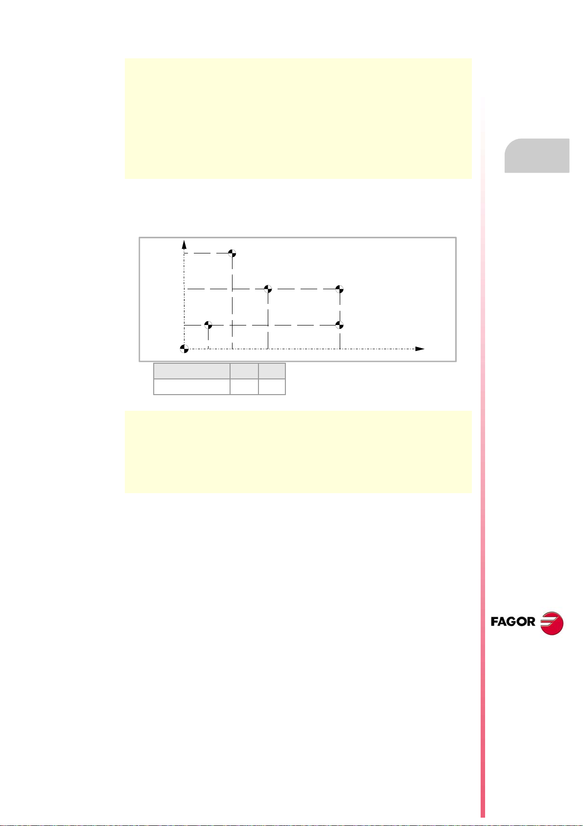
Programming manual
Y
X
80
W
50
20
20 40 70 120
W
W
W
W
M
X Y
G54 (G159=1) 20 20
N100 G54 (It applies the first absolute zero offset)
··· (Machining of profile A1)
N200 G158 Z-90 (Apply incremental zero offset)
··· (Machining of profile A2)
N300 G55 (It applies the second absolute zero offset)
··· (Machining of profile A3)
N200 G158 Z-180 (It applies the second incremental zero offset)
··· (Machining of profile A4)
Only one incremental zero may be active at a time for each axis; therefore, applying an
incremental zero offset on an axis cancels the one that was active on that axis. The offsets
on the rest of the axes are not affected.
(The incremental zero offset is still active)
5.
ORIGIN SELECTION
Zero offsets (G54-G59/G159)
N100 G54 (Apply absolute zero offset)
N200 G158 X20 Y60 (It applies the first incremental zero offset)
N300 G158 X50 Y30 (It applies the second incremental zero offset)
N400 G158 X100 (It applies the third incremental zero offset)
N500 G158 Y0 (It applies the fourth incremental zero offset)
N600 G158 X0 (Cancel incremental zero offset)
The incremental zero offset is not canceled after applying a new absolute zero offset (G54G59 or G159).
Considerations
An incremental zero offset, by itself, does not cause any axis movement.
When homing an axis in JOG mode, the incremental zero offset for that axis is canceled.
Properties of the function
Function G158 is modal.
On power-up, the CNC assumes the incremental zero offset that was active when the CNC
was turned off. On the other hand, the incremental zero offset is neither affected by functions
M02 and M30 nor by RESETTING the CNC.
CNC 8070
(REF. 1309)
·91·
Page 92

5.
ORIGIN SELECTION
Zero offsets (G54-G59/G159)
Programming manual
5.5.3 Excluding axes in the zero offset (G157)
Excluding axes allows to select on to which axes the next absolute zero offset will not be
applied. After applying the zero offset, the programmed axis exclusion is canceled and it has
to be programmed again in order to apply it again.
Activation
Axis exclusion must be programmed using function G157 followed by the axes and the value
indicating whether that axis is excluded (<axis>=1) or not (<axis>=0).
The exclusion may also be activated by programming only the axes affected by the exclusion
after function G157.
The exclusion and the zero offset may be programmed in the same block. In that case, the
exclusion will be activated before applying the zero offset.
G55
(It applies the second zero offset on all the axes)
G157 X Z
(Activation of the exclusion on the X-Z axes)
G57
(It applies the fourth zero offset, except on the X-Z axes. These axes keep the previous zero offset)
···
G159=8
(It applies the eighth zero offset on all the axes)
G59 G157 Y
(It applies the sixth zero offset, except on the Y axis. That axis keeps the previous zero offset)
···
G54
(It applies the first zero offset on all the axes)
Excluding axes does not affect the active zero offsets. If an axis is excluded, when applying
a new zero offset, the CNC maintains the one that was active for that axis.
Considerations
Excluding axes does not affect the coordinate preset or the incremental zero offsets which
are always applied on to all the axes. Likewise, neither fixture offsets nor PLC offsets are
affected.
Properties of the function
Function G157 is modal and it remains active until an absolute zero offset is applied.
On power-up or after an EMERGENCY, the CNC does not assume any axis exclusion.
CNC 8070
(REF. 1309)
·92·
Page 93

Programming manual
Y
X
Ow
O
M
O
F
Y
X
5.6 Zero offset cancellation (G53)
Executing function G53 cancels the active zero offset resulting either from a preset (G92)
or from a zero offset, including the incremental offset and the defined axis exclusion. It also
cancels the zero offset due to a probing operation.
Fixture offsets and PLC offsets are not affected by this function.
Contrary to the #MCS and #MCS ON/OFF instructions that always execute movements
referred to machine zero, function G53 allows to execute movements referred to the fixture
zero (if it is active).
N10 V.G.FIX=1 (Activate fixture offset. Program with respect to OF)
N20 G54 (Apply the zero offset. Program with respect to OW)
N30 #MCS X20 Y20 (Activate machine coordinate system. Program with respect to OM)
N40 G01 X60 Y0 (Program with respect to OW)
N50 G53 (Cancel zero offset G54. Program with respect to OF)
5.
ORIGIN SELECTION
Zero offset cancellation (G53)
Function G53 may be programmed in any block of the program. When added to a block with
path information, the offset or preset is canceled before executing the programmed
movement.
Considerations
Function G53, by itself, does not cause any axis movement.
Properties of the function
Function G53 is modal and incompatible with function G92, zero offsets and probing.
CNC 8070
(REF. 1309)
·93·
Page 94

5.
Y
X
30
35
P3
P1
P2
P0
ORIGIN SELECTION
Programming manual
5.7 Polar origin preset (G30)
Function G30 may be used to preset any point of the work plane as the new polar origin. If
not selected, it assumes as polar origin the origin of the active reference system (part zero).
Programming
The polar origin preset must be programmed alone in the block. The programming format
is "G30 I J", where:
They define the abscissa and ordinate of the new polar origin. They must be defined in absolute
I, J
coordinates referred to part zero.
When programmed, both parameters must be programmed.
If not programmed, it will assume the current tool position as the polar origin.
Therefore, function G30 may be programmed as follows:
G30 I J It assumes as the new polar origin the point whose abscissa is "I" and ordinate "J" referred
to part zero.
G30 The current tool position is assumed as the new polar origin.
Polar origin preset (G30)
CNC 8070
Assuming the initial point is X0 Y0:
G30 I35 J30 (Preset P3 as the polar origin)
G90 G01 R25 Q0 (Point P1)
G03 Q90 (Point P2)
G01 X0 Y0 (Point P0)
M30
(REF. 1309)
·94·
Page 95

Programming manual
X
Z
P0
50
80
90
130
170
P1
P2
P3
P5
P4P6
90
40
G18 G151 ; Main plane Z-X, and programming in diameters.
G90 X180 Z50 ; Point P0, programming in diameters.
G01 X160 ; Point P1, in a straight line (G01).
G30 I90 J160 ; Presets P5 as polar origin.
G03 Q270 ; Point P2, in arc (G03).
G01 Z130 ; Point P3, in a straight line (G01).
G30 I130 J0 ; Presets P6 as polar origin.
G02 Q0 ; Point P4, in arc (G02).
5.
ORIGIN SELECTION
Polar origin preset (G30)
Properties of the function
Function G30 is modal. The polar origin stays active until another value is preset or the work
plane is changed. When changing the work plane, it assumes the part zero of that plane as
the new polar origin.
On power-up, after an M02 or M30 and after an EMERGENCY or a RESET, the CNC
assumes the currently selected part zero as the new polar origin.
CNC 8070
(REF. 1309)
·95·
Page 96

5.
Programming manual
ORIGIN SELECTION
Polar origin preset (G30)
CNC 8070
(REF. 1309)
·96·
Page 97

TECHNOLOGICAL FUNCTIONS
6.1 Machining feedrate (F)
The machining feedrate may be selected by programmed using the "F" code which remains
active until another value is programmed. The programming units depend on the active work
mode (G93, G94 or G95) and the type of axis being moved (linear or rotary).
G94 - Feedrate in millimeters/minute (inches/minute).
G95 - Feedrate in millimeters/revolution (inches/revolution).
G93 - Machining time in seconds.
The programmed "F" is effective in linear (G01) or circular (G02, G03) interpolations.
Movements in G00 (rapid traverse) are executed in rapid regardless of the programmed "F"
value.
6
Movement without programmed feedrate.
In principle, the CNC will show the corresponding error when programming a movement in
G01/G02/G03 without having set a feedrate.
Optionally, the manufacturer may have configured the CNC to make the movements at the
maximum machining feedrate, set by machine parameter MAXFEED.
Feedrate limitation.
The manufacturer may have limited the maximum feedrate with machine parameter
MAXFEED. When trying to exceed the maximum feedrate via part-program, via PLC or from
the operator panel, the CNC limits the feedrate to the maximum value set without showing
any error message or warning.
If this parameter is set to zero, the machining feedrate is not limited and the CNC assumes
the one set for G00 as the maximum feedrate.
Variable to limit the feedrate via PLC.
(V.)[n].PLC.G00FEED is a variable that may be written from the PLC to set, at a particular
moment and in real time, the maximum feedrate of the channel for any type of movement.
Feedrate regulation.
The programmed feedrate "F" may be varied between 0% and 200% using the selector switch
on the CNC's operator panel or it may be selected by program or by PLC. However, the
maximum override is limited by the machine manufacturer [G.M.P. "MAXOVR"].
CNC 8070
When making movements in G00 (rapid traverse), the feedrate override percentage will be
fixed at 100% or it may be varied between 0% and 100% depending on how the machine
manufacturer has set [G.M.P. "RAPIDOVR"].
When carrying out threading operations, the feedrate percentage will be fixed at 100% of
the programmed feedrate.
(REF. 1309)
·97·
Page 98
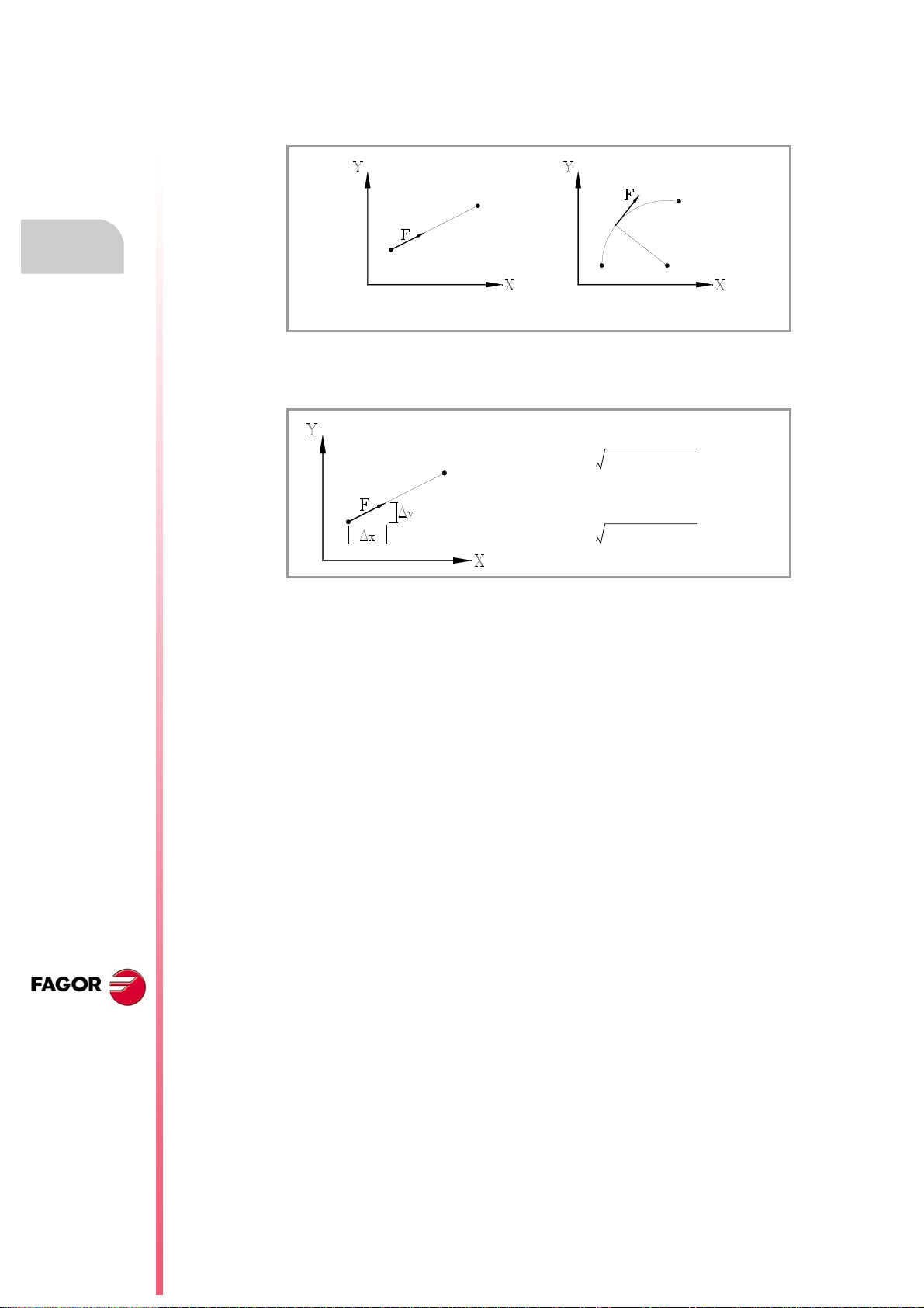
6.
Feedrate direction on linear and circular interpolations.
Fx
F Δx⋅
Δx()
2
Δy()
2
+()
------------------------------------------- -
=
Fy
F Δy⋅
Δx()
2
Δy()
2
+()
------------------------------------------- -
=
Programming manual
Understanding how the CNC calculates the feedrate.
The feedrate is measured along the tool path, either along the straight line (linear
interpolations) or along the tangent of the indicated arc (circular interpolations).
When only the main axes are involved in the interpolation, the relationship between the
components of the feedrate on each axis and the programmed "F" is the same as between
the displacement of each axis and the resulting programmed displacement.
Machining feedrate (F)
TECHNOLOGICAL FUNCTIONS
CNC 8070
When rotary axes are involved in the interpolations, the feedrate of these axes is calculated
so the beginning and the end of their movement coincides with the beginning and the end
of the main axes. If the feedrate calculated for the rotary axis is greater than the maximum
allowed, the CNC will adapt the programmed "F" so the rotary axis can turn at its maximum
speed.
(REF. 1309)
·98·
Page 99
Programming manual
6.2 Feedrate related functions
6.2.1 Feedrate programming units (G93/G94/G95)
The functions related to programming units permit selecting whether mm/minute
(inches/minute) or mm/revolution (inches/rev.) are programmed or, instead, the time the axes
will take to reach their target position.
Programming
The functions related to programming units are:
G94 Feedrate in millimeters/minute (inches/minute).
G95 Feedrate in millimeters/revolution (inches/revolution).
G93 Machining time in seconds.
These functions may be programmed anywhere in the program and they don't have to go
alone in the block. If the moving axis is rotary, the programming units will be in degrees
instead of millimeters or inches as follows:
Linear axes Rotary axes
G94 millimeters (inches)/minute degrees/minute
G95 millimeters (inches)/revolution degrees/revolution
G93 seconds seconds
G94
Feedrate in millimeters/minute (inches/minute).
After executing G94, the CNC interprets that the feedrates programmed with the "F" code
are in millimeters/minute (inches/minute). If the moving axis is rotary, the CNC interprets that
the programmed feedrate is in degrees/minute.
6.
Feedrate related functions
TECHNOLOGICAL FUNCTIONS
G95
Feedrate in millimeters/revolution (inches/revolution)
After executing G95, the CNC interprets that the feedrates programmed with the "F" code
are in mm/rev (inches/rev) of the master spindle of the channel. If the moving axis is rotary,
the CNC interprets that the programmed feedrate is in degrees/revolution.
If the spindle does not have an encoder, the CNC will use the programmed theoretical rpm
to calculate the feedrate. This function does not affect the movements in G00 which are
always executed in millimeters/minute (inches/minute).
G93
Machining time in seconds
After executing G93, the CNC interprets that the movements must be carried out in the time
period (seconds) indicated by the "F" code.
This function does not affect the movements in G00 which are always executed in
millimeters/minute (inches/minute).
Properties of the functions
Functions G93,G94 and G95 are modal and incompatible with each other.
On power-up, after an M02 or M30 and after an EMERGENCY or a RESET, the CNC
assumes function G94 or G95 as set by the machine manufacturer [G.M.P. "IFEED"].
CNC 8070
(REF. 1309)
·99·
Page 100
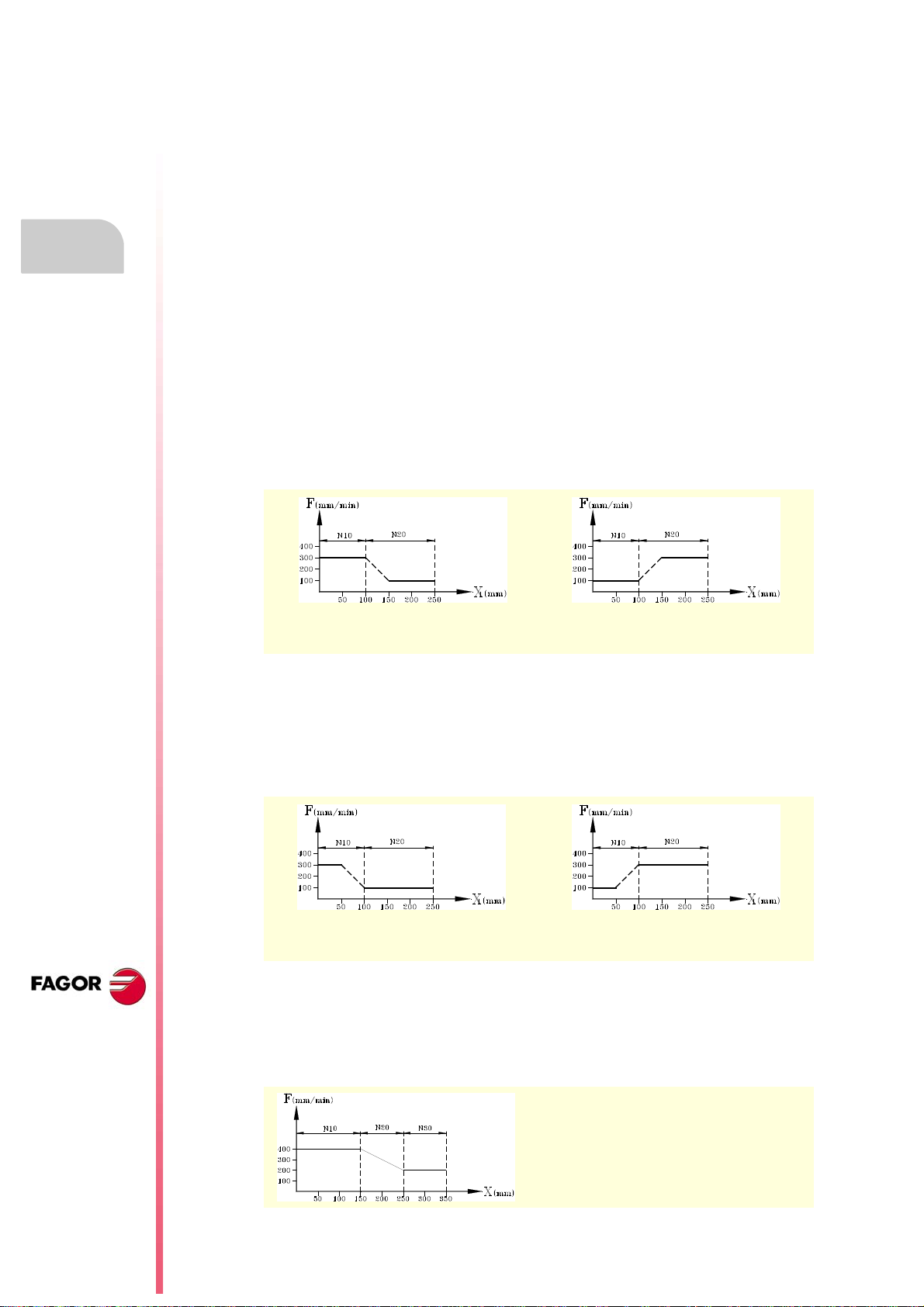
6.
Programming manual
6.2.2 Feedrate blend (G108/G109/G193)
With these functions, it is possible to blend the feedrate between consecutive blocks
programmed with different feedrates.
Programming
The functions related to feedrate blending are:
G108 Feedrate blending at the beginning of the block.
G109 Feedrate blending at the end of the block.
G193 Interpolating the feedrate.
These functions may be programmed anywhere in the program and they don't have to go
alone in the block.
G108
Feedrate blending at the beginning of the block
Feedrate related functions
TECHNOLOGICAL FUNCTIONS
When G108 is active, the adaptation to the new feedrate (by accelerating or decelerating)
takes place at the beginning of the next block and the current block ends at the programmed
feedrate "F".
N10 G01 G108 X100 F300 N10 G01 G108 X100 F100
N20 X250 F100 N20 X250 F300
G109
Feedrate blending at the end of the block
When programming G109 the adaptation to the new feedrate (by accelerating or
decelerating) takes place at the end of the current block so the next block starts executing
at its programmed feedrate "F".
CNC 8070
(REF. 1309)
·100·
N10 G01 G109 X100 F300 N10 G01 G109 X100 F100
N20 X250 F100 N20 X250 F300
G193
Interpolating the feedrate
When programming G193, the adaptation to the new feedrate is interpolated linearly during
the movement programmed in the block.
N10 G01 X150 F400
N20 G193 X250 F200
N30 X350
 Loading...