

Page 1

CNC
8070
Operating manual
(Ref: 1309)
Page 2

MACHINE SAFETY
It is up to the machine manufacturer to make sure that the safety of the machine
is enabled in order to prevent personal injury and damage to the CNC or to the
products connected to it. On start-up and while validating CNC parameters, it
checks the status of the following safety elements. If any of them is disabled, the
CNC shows a warning message.
• Feedback alarm for analog axes.
• Software limits for analog and sercos linear axes.
• Following error monitoring for analog and sercos axes (except the spindle)
both at the CNC and at the drives.
• Tendency test on analog axes.
FAGOR AUTOMATION shall not be held responsible for any personal injuries or
physical damage caused or suffered by the CNC resulting from any of the safety
elements being disabled.
HARDWARE EXPANSIONS
FAGOR AUTOMATION shall not be held responsible for any personal injuries or
physical damage caused or suffered by the CNC resulting from any hardware
manipulation by personnel unauthorized by Fagor Automation.
If the CNC hardware is modified by personnel unauthorized by Fagor Automation,
it will no longer be under warranty.
COMPUTER VIRUSES
FAGOR AUTOMATION guarantees that the software installed contains no
computer viruses. It is up to the user to keep the unit virus free in order to
guarantee its proper operation.
Computer viruses at the CNC may cause it to malfunction. An antivirus software
is highly recommended if the CNC is connected directly to another PC, it is part
of a computer network or floppy disks or other computer media is used to transmit
data.
FAGOR AUTOMATION shall not be held responsible for any personal injuries or
physical damage caused or suffered by the CNC due a computer virus in the
system.
If a computer virus is found in the system, the unit will no longer be under warranty.
All rights reserved. No part of this documentation may be transmitted,
transcribed, stored in a backup device or translated into another language
without Fagor Automation’s consent. Unauthorized copying or distributing of this
software is prohibited.
The information described in this manual may be changed due to technical
modifications. Fagor Automation reserves the right to make any changes to the
contents of this manual without prior notice.
All the trade marks appearing in the manual belong to the corresponding owners.
The use of these marks by third parties for their own purpose could violate the
rights of the owners.
It is possible that CNC can execute more functions than those described in its
associated documentation; however, Fagor Automation does not guarantee the
validity of those applications. Therefore, except under the express permission
from Fagor Automation, any CNC application that is not described in the
documentation must be considered as "impossible". In any case, Fagor
Automation shall not be held responsible for any personal injuries or physical
damage caused or suffered by the CNC if it is used in any way other than as
explained in the related documentation.
The content of this manual and its validity for the product described here has been
verified. Even so, involuntary errors are possible, thus no absolute match is
guaranteed. Anyway, the contents of the manual is periodically checked making
and including the necessary corrections in a future edition. We appreciate your
suggestions for improvement.
The examples described in this manual are for learning purposes. Before using
them in industrial applications, they must be properly adapted making sure that
the safety regulations are fully met.
Page 3

Operating manual
INDEX
About the product ......................................................................................................................... 9
Declaration of conformity............................................................................................................ 11
Version history............................................................................................................................ 13
Safety conditions ........................................................................................................................ 23
Warranty terms ........................................................................................................................... 27
Material returning terms.............................................................................................................. 29
CNC maintenance ...................................................................................................................... 31
CHAPTER 1 DESCRIPTION OF THE KEYS
1.1 Monitor LCD-15. ............................................................................................................ 33
1.2 Monitor LCD-10K. ......................................................................................................... 34
1.3 HORIZONTAL KEYB / HORIZONTAL KEYB + MOUSE. ........................................ 36
1.4 VERTICAL KEYB / VERTICAL KEYB + MOUSE. .................................................... 37
1.5 OP PANEL / OP PANEL + SPDL RATE. ................................................................. 38
1.6 Keyboard shortcuts........................................................................................................ 39
CHAPTER 2 GENERAL CONCEPTS
2.1 Turning the CNC on and off ........................................................................................... 41
2.1.1 Emergency shutdown with battery ............................................................................. 43
2.2 Work modes and software protection at the CNC.......................................................... 44
2.3 Network connection (Ethernet) ...................................................................................... 46
2.4 Directory structure..........................................................................................................47
2.4.1 MTB (Machine Tool Builder) directory........................................................................ 48
2.4.2 USERS directory........................................................................................................ 49
CHAPTER 3 HOW TO OPERATE THE CNC
3.1 General description of the interface. .............................................................................. 51
3.2 Detailed description of the CNC status bar.................................................................... 52
3.2.1 Channel synchronization window............................................................................... 53
3.2.2 PLC messages........................................................................................................... 54
3.3 Horizontal softkey menu ................................................................................................ 55
3.4 Operating modes ........................................................................................................... 56
3.4.1 Description of the various operating modes............................................................... 58
3.5 Task window ..................................................................................................................60
3.6 Windows for warnings and errors .................................................................................. 61
3.6.1 CNC warnings and errors........................................................................................... 61
3.6.2 PLC errors.................................................................................................................. 62
3.7 File selection window..................................................................................................... 63
3.8 Calculator....................................................................................................................... 65
3.8.1 Defining expressions.................................................................................................. 67
3.9 Dialog boxes .................................................................................................................. 69
CHAPTER 4 AUTOMATIC MODE
4.1 Interface description....................................................................................................... 71
4.1.1 Softkey menus. .......................................................................................................... 73
4.2 Display the status of the program or of the active subroutines. ..................................... 74
4.3 Program simulation and execution................................................................................. 75
4.3.1 Select program........................................................................................................... 75
4.3.2 Select the first and last blocks of the execution. ........................................................ 76
4.3.3 Execute a program..................................................................................................... 79
4.3.4 Resume the execution of a program from the block where it was canceled. ............. 80
4.3.5 Cancel the execution and resume from another block while keeping the history. ..... 81
4.3.6 Simulated execution of a program. ............................................................................ 82
4.3.7 Execute a program (retrace). ..................................................................................... 85
4.3.8 Executing a program in 8055 MC/TC language. ........................................................ 88
4.4 Executing program blocks separately. ........................................................................... 89
4.5 Tool inspection. ............................................................................................................. 90
4.5.1 Tool inspection (execution in retrace mode, independent interpolator or rigid tapping).
93
4.6 Block search. ................................................................................................................. 95
4.6.1 Treatment of functions M, H, F, S. ............................................................................. 97
CNC 8070
(REF: 1309)
·3·
Page 4

CHAPTER 5 MANUAL (JOG) MODE
5.1 Interface description. ..................................................................................................... 99
5.1.1 Softkey menus. ........................................................................................................ 101
5.2 Operations with the axes. ............................................................................................ 102
5.2.1 Home search............................................................................................................ 102
5.2.2 Jog ........................................................................................................................... 103
5.2.3 Jogging the axes with handwheels .......................................................................... 105
5.2.4 Moving an axis to a particular position (coordinate)................................................. 107
5.2.5 Coordinate preset .................................................................................................... 107
5.3 Spindle control ............................................................................................................. 108
5.4 Tool selection and tool change .................................................................................... 109
5.5 Setting the feedrate and spindle speed. ...................................................................... 110
5.6 Setting and activating the zero offsets and the fixture offsets. .................................... 111
CHAPTER 6 MANUAL (JOG) MODE. TOOL CALIBRATION
6.1 Manual calibration. Calibration without a probe........................................................... 115
6.2 Semi-automatic calibration. Calibration with a probe................................................... 119
6.3 Automatic calibration with a probe and a canned cycle............................................... 122
6.3.1 Mill or lathe model ("trihedron" geometrical configuration)....................................... 122
6.3.2 Lathe model ("plane" geometrical configuration) ..................................................... 125
CHAPTER 7 MANUAL (JOG) MODE. PART CENTERING (MILL MODEL)
7.1 How to define the data................................................................................................. 128
7.2 Data programming. ...................................................................................................... 129
7.3 Basic operation. ........................................................................................................... 132
Operating manual
CNC 8070
CHAPTER 8 EDISIMU MODE (EDITING AND SIMULATION)
8.1 Interface description. ................................................................................................... 135
8.1.1 Softkey menus. ........................................................................................................ 137
8.2 Program editing and simulation ................................................................................... 138
8.2.1 Program editing........................................................................................................ 138
8.2.2 Editing a program in the 8055 CNC language ......................................................... 139
8.2.3 Program simulation .................................................................................................. 141
8.2.4 Simulation errors...................................................................................................... 143
8.3 Editing window............................................................................................................. 144
8.3.1 Softkey and hotkey menus....................................................................................... 146
8.3.2 Contextual programming assistance........................................................................ 147
8.3.3 Help for programming subroutines........................................................................... 148
8.3.4 Syntax errors when editing ...................................................................................... 149
8.4 Working in the editing window. .................................................................................... 150
8.4.1 Select a program...................................................................................................... 150
8.4.2 Operations with blocks. Cut and paste. ................................................................... 150
8.4.3 Find a line or a text in the program. ......................................................................... 151
8.4.4 Undo and redo. ........................................................................................................ 152
8.4.5 Operations with files................................................................................................. 153
8.4.6 Customizing the editor. ............................................................................................ 154
8.4.7 TEACH-IN ................................................................................................................ 156
8.4.8 Import DXF files ....................................................................................................... 157
8.4.9 Profile editor............................................................................................................. 158
8.4.10 Canned cycle editor. ................................................................................................ 158
8.4.11 Inclined planes (·M· model)...................................................................................... 159
8.4.12 Geometric-help editor (·M· model) ........................................................................... 160
8.5 Graphics window ......................................................................................................... 161
8.6 Program window .......................................................................................................... 162
8.7 Working in the program window. ................................................................................. 163
8.7.1 Select the first and last blocks of the execution. ...................................................... 163
8.7.2 Simulate program blocks separately........................................................................ 164
8.7.3 Display the status of the program or of the active subroutines. ............................... 165
8.8 Statistics window ......................................................................................................... 166
8.8.1 Time estimates......................................................................................................... 167
(REF: 1309)
·4·
CHAPTER 9 PROFILE EDITOR
9.1 Interface description. ................................................................................................... 169
9.1.1 How to use the profile editor. ................................................................................... 171
Page 5

Operating manual
9.2 Define a new profile, enlarge an existing one or import one from a file. ...................... 172
9.2.1 Define any profile using straight and curved sections.............................................. 173
9.2.2 Define a circular profile. ........................................................................................... 175
9.2.3 Define a rectangular profile. ..................................................................................... 176
9.2.4 Enlarge a profile....................................................................................................... 176
9.2.5 Import a profile from a DXF file. ............................................................................... 177
9.3 Modify a profile and insert corners............................................................................... 179
9.4 Configuring the profile editor. Displayed area.............................................................. 181
9.5 Configuring the profile editor. Define the work plane. .................................................. 181
9.6 End the session at the editor. ...................................................................................... 181
9.7 Examples of how to define profiles. ............................................................................. 182
9.7.1 Profile editor. Example 1 (milling). ........................................................................... 182
9.7.2 Profile editor. Example 2 (milling). ........................................................................... 183
9.7.3 Profile editor. Example 3 (milling). ........................................................................... 185
9.7.4 Profile editor. Example 4 (lathe)............................................................................... 186
CHAPTER 10 GRAPHIC ENVIRONMENT (MILL MODEL)
10.1 Description of the graphic environment. ...................................................................... 187
10.1.1 Softkey menus. ........................................................................................................ 188
10.2 Type of graphics .......................................................................................................... 189
10.3 Zoom............................................................................................................................ 190
10.4 Dimensions .................................................................................................................. 191
10.5 Point of view................................................................................................................. 191
10.6 Measurement ............................................................................................................... 192
10.7 Clear screen................................................................................................................. 193
10.8 Colors........................................................................................................................... 193
10.9 Options......................................................................................................................... 194
10.10 Real coordinates .......................................................................................................... 195
10.11 Real coordinates with enlarged error ........................................................................... 195
10.12 Simulation speed ......................................................................................................... 195
CHAPTER 11 HD GRAPHIC ENVIRONMENT (MILL MODEL)
11.1 Description of the graphic environment. ...................................................................... 197
11.1.1 Softkey menus. ........................................................................................................ 198
11.2 Move, rotate and zoom in or out on the graphic. ......................................................... 199
11.3 Select the type of view................................................................................................. 200
11.4 Configure the graphics (number of windows, colors, etc.). .......................................... 201
11.5 Actions (move sections and print graphics). ................................................................ 204
11.6 Delete the graphic........................................................................................................ 205
11.7 Define the dimensions of the parts and the size of the graphic. .................................. 205
11.8 Measure the part.......................................................................................................... 206
11.9 Simulation speed. ........................................................................................................ 206
CHAPTER 12 GRAPHIC ENVIRONMENT (LATHE MODEL)
12.1 Description of the graphic environment. ...................................................................... 207
12.1.1 Softkey menus. ........................................................................................................ 208
12.2 Type of graphics .......................................................................................................... 209
12.3 Zoom............................................................................................................................ 210
12.4 Dimensions .................................................................................................................. 211
12.5 Measurement ............................................................................................................... 211
12.6 Clear screen................................................................................................................. 212
12.7 Colors........................................................................................................................... 212
12.8 Options......................................................................................................................... 213
12.9 Real coordinates .......................................................................................................... 214
12.10 Real coordinates with enlarged error ........................................................................... 214
12.11 Simulation speed ......................................................................................................... 214
CHAPTER 13 HD GRAPHIC ENVIRONMENT (LATHE MODEL)
13.1 Description of the graphic environment. ...................................................................... 215
13.1.1 Softkey menus. ........................................................................................................ 216
13.2 Move, rotate and zoom in or out on the graphic. ......................................................... 217
13.3 Select the type of view................................................................................................. 218
13.4 Configure the graphics (number of windows, colors, etc.). .......................................... 219
13.5 Actions (move sections and print graphics). ................................................................ 222
13.6 Delete the graphic........................................................................................................ 223
13.7 Define the dimensions of the parts and the size of the graphic. .................................. 223
13.8 Measure the part.......................................................................................................... 224
13.9 Simulation speed. ........................................................................................................ 224
CNC 8070
(REF: 1309)
·5·
Page 6

CHAPTER 14 MDI/MDA MODE
14.1 Interface description. ................................................................................................... 225
14.1.1 Softkey menus. ........................................................................................................ 226
14.2 Edit and execute individual blocks............................................................................... 227
14.3 Block history. ............................................................................................................... 228
CHAPTER 15 USER TABLES
15.1 User table presentation................................................................................................ 229
15.1.1 Softkey menus. ........................................................................................................ 230
15.2 Zero offset tables ......................................................................................................... 231
15.3 Fixture table ................................................................................................................. 233
15.4 Arithmetic parameter tables......................................................................................... 234
15.5 Operations with tables ................................................................................................. 235
15.5.1 Data editing.............................................................................................................. 235
15.5.2 Save and recall tables.............................................................................................. 235
15.5.3 Find text. ................................................................................................................. 237
CHAPTER 16 TOOL AND MAGAZINE TABLE
16.1 Presentation of the tool tables and magazine tables. ................................................. 239
16.1.1 Softkey menus. ........................................................................................................ 240
16.1.2 Search for a text in the tables .................................................................................. 241
16.1.3 Save and load the tables ......................................................................................... 242
16.1.4 Printing the tables .................................................................................................... 244
16.2 Tool table ..................................................................................................................... 245
16.2.1 Softkey menus. ........................................................................................................ 246
16.2.2 The tool list............................................................................................................... 247
16.2.3 Description of the tool data ...................................................................................... 248
16.3 Operations with the tool table ...................................................................................... 256
16.3.1 Editing the tool table ................................................................................................ 256
16.4 Active-tools table ......................................................................................................... 257
16.4.1 Softkey menus. ........................................................................................................ 258
16.4.2 Changing the tool of the spindle .............................................................................. 258
16.5 Table for the status of the tool change process........................................................... 259
16.6 Magazine table ............................................................................................................ 260
16.6.1 Softkey menus. ........................................................................................................ 261
16.6.2 List of magazine positions........................................................................................ 262
16.6.3 Magazine information............................................................................................... 263
16.7 Operations with the magazine table ............................................................................ 265
16.7.1 Loading / unloading tools to / from the magazine .................................................... 265
16.7.2 Load / unload a tool to / from the tool changer arm ................................................. 267
Operating manual
CNC 8070
(REF: 1309)
CHAPTER 17 UTILITIES MODE
17.1 Interface description. ................................................................................................... 269
17.1.1 Softkey menus. ........................................................................................................ 270
17.2 Set how to display the list of programs. ....................................................................... 271
17.3 Select files and create folders...................................................................................... 272
17.4 Search in files .............................................................................................................. 273
17.5 Protection passwords .................................................................................................. 274
17.6 Data safety backup. Backup - Restore ........................................................................ 276
17.7 Encrypting files ............................................................................................................ 278
CHAPTER 18 PLC
18.1 Appearance of the PLC mode ..................................................................................... 279
18.1.1 Icon description (vertical softkeys)........................................................................... 280
18.2 "Programs" service ...................................................................................................... 281
18.2.1 Softkey menus. PLC project. ................................................................................... 282
18.2.2 Softkey menus. Files of the PLC project.................................................................. 283
18.3 Program editing ........................................................................................................... 284
18.4 Editing in C language or mnemonic language. ............................................................ 286
18.4.1 Softkey "Analyze"..................................................................................................... 287
18.4.2 Softkey "File". .......................................................................................................... 287
18.4.3 Softkey "Undo"......................................................................................................... 287
18.4.4 Softkey "Operations with blocks". ............................................................................ 288
18.4.5 Softkey "Find/Replace". ........................................................................................... 289
18.4.6 Softkey "Customize". ............................................................................................... 290
·6·
Page 7

Operating manual
18.5 Editing in contact (ladder) language (softkeys)............................................................ 291
18.5.1 Softkey "Analyze"..................................................................................................... 292
18.5.2 Softkey "File". .......................................................................................................... 292
18.5.3 "Edit" softkey. .......................................................................................................... 293
18.5.4 Softkey "View". ........................................................................................................ 295
18.5.5 Softkey "Marks". ...................................................................................................... 295
18.5.6 Softkey "Find"........................................................................................................... 296
18.5.7 Softkey "Customize"................................................................................................. 296
18.6 Program monitoring ..................................................................................................... 297
18.6.1 Softkey menus. Monitoring in C language or mnemonic language. ........................ 298
18.6.2 Softkey menus. Monitoring in contact (ladder) language. ....................................... 299
18.7 "Commands" service.................................................................................................... 301
18.7.1 Softkey menus. Options of the "Commands" service............................................... 301
18.8 "Outputs" service ......................................................................................................... 302
18.8.1 Softkey menus. Options of the "Outputs" service. ................................................... 303
18.9 "Logic analyzer" service............................................................................................... 304
18.9.1 Editing logic analyzer data ....................................................................................... 305
18.9.2 Save, load and reset the analyzer configuration ...................................................... 307
18.9.3 Execute and analyze trace....................................................................................... 308
18.9.4 Customize the appearance of the logic analyzer ..................................................... 308
18.10 "Monitoring" service ..................................................................................................... 309
18.10.1 Description of resource tables.................................................................................. 310
18.10.2 Definition of the table resources............................................................................... 311
18.10.3 Options of the "Monitoring" service (softkeys). ........................................................ 312
18.11 "Cross references" service........................................................................................... 313
18.11.1 Softkey menus. Options of the "Cross reference" service. ...................................... 314
18.12 "Statistics" service........................................................................................................ 315
18.12.1 Softkey menus. Options of the "Statistics" service................................................... 316
18.13 "Messages" service...................................................................................................... 317
18.13.1 Softkey menus. Options of the "Messages" service................................................. 318
18.13.2 Editing the message and error table ........................................................................ 319
18.13.3 Displaying PLC messages ....................................................................................... 320
18.13.4 Displaying PLC errors .............................................................................................. 321
18.13.5 Grouping the additional information text files in a single file. ................................... 322
18.13.6 Save, load and print a message and error table ...................................................... 323
CHAPTER 19 MACHINE PARAMETERS
19.1 Appearance of the machine parameter tables ............................................................. 325
19.1.1 Softkey menus. ........................................................................................................ 326
19.2 Parameter table description ......................................................................................... 327
19.2.1 "M" function setting table.......................................................................................... 328
19.2.2 Compensation table ................................................................................................. 329
19.2.3 OEM parameters...................................................................................................... 330
19.3 Operations with tables ................................................................................................. 331
19.3.1 Data editing and validation....................................................................................... 331
19.3.2 Save and recall tables.............................................................................................. 332
19.3.3 Find text. ................................................................................................................. 333
19.3.4 Importing and exporting compensation tables. ........................................................ 334
CHAPTER 20 SETUP ASSISTANCE
20.1 Oscilloscope................................................................................................................. 336
20.1.1 Interface description................................................................................................. 337
20.1.2 Softkey menus. ........................................................................................................ 338
20.1.3 Configuration screen ................................................................................................ 341
20.1.4 Configure and execute the oscilloscope function..................................................... 342
20.1.5 Machine parameter editing. ..................................................................................... 343
20.2 The Bode diagram ....................................................................................................... 346
20.2.1 Interface description................................................................................................. 347
20.2.2 Softkey menus. ........................................................................................................ 348
20.2.3 Machine parameter editing. ..................................................................................... 351
20.2.4 Configuration screen ................................................................................................ 353
20.3 The circularity (roundness) test.................................................................................... 356
20.3.1 Interface description................................................................................................. 357
20.3.2 Softkey menus. ........................................................................................................ 359
20.3.3 Configuring and executing the circularity (roundness) test ...................................... 360
20.3.4 Configure the graphic environment .......................................................................... 361
20.3.5 Define and execute the movement subroutine......................................................... 362
20.3.6 Data capture for the graphic..................................................................................... 363
20.3.7 Adjustment of the machine parameters involved ..................................................... 364
20.3.8 Validate the changes and save the configuration used............................................ 366
20.3.9 Machine parameters that may be modified .............................................................. 367
CNC 8070
(REF: 1309)
·7·
Page 8

CHAPTER 21 DDSSETUP
21.1 Appearance of the DDSSetup mode ........................................................................... 369
21.1.1 Icon description (vertical softkeys)........................................................................... 370
21.2 List of devices connected to the bus............................................................................ 371
21.3 Drives accessing level (only Sercos). .......................................................................... 373
21.4 –Parameters and variables– service. .......................................................................... 374
21.5 –Error management– service. ..................................................................................... 376
21.6 –Monitoring– service.................................................................................................... 377
21.7 –Information– service .................................................................................................. 379
21.8 Command generator (only Sercos). ............................................................................ 381
21.9 Command line.............................................................................................................. 382
21.10 File for setting the parameters of Mechatrolink servos. ............................................... 384
CHAPTER 22 DIAGNOSIS
22.1 Appearance of the diagnosis mode. ............................................................................ 387
22.1.1 Softkey menus. ........................................................................................................ 388
22.2 Configuration diagnosis ............................................................................................... 389
22.2.1 System diagnosis..................................................................................................... 389
22.2.2 Software diagnosis................................................................................................... 390
22.2.3 Hardware diagnosis. Bus CAN, Sercos and Mechatrolink. ...................................... 391
22.3 Sercos diagnosis ......................................................................................................... 393
22.4 Save the CAN configuration for the start-up test. ........................................................ 394
22.5 Report generation ........................................................................................................ 395
22.6 View the history of errors and warnings issued by the CNC........................................ 396
22.7 Generating the Fagor file for error diagnosis. .............................................................. 396
Operating manual
CNC 8070
(REF: 1309)
·8·
Page 9

Operating manual
ABOUT THE PRODUCT
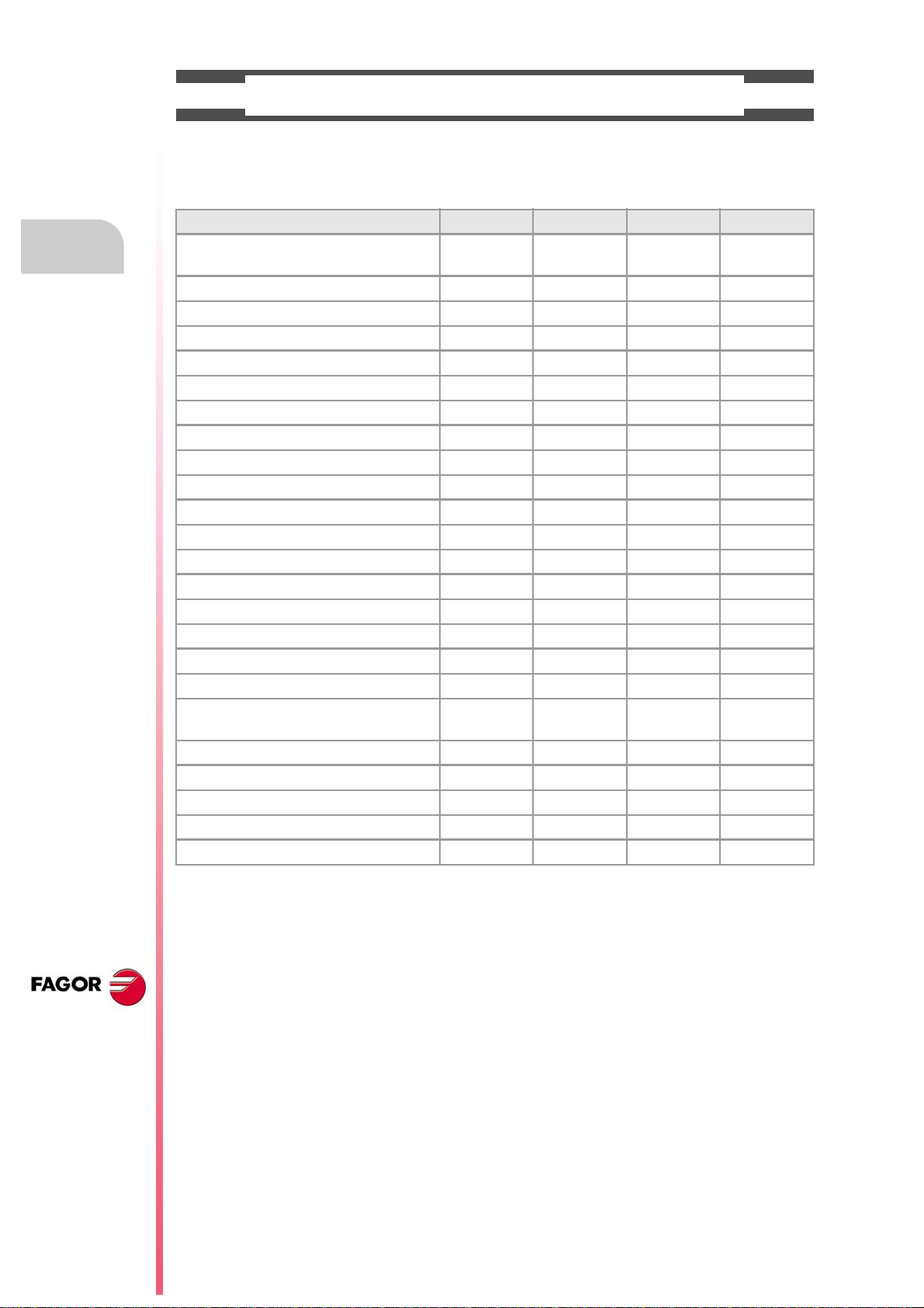
BASIC CHARACTERISTICS.
Basic characteristics. ·BL· ·OL· ·M· / ·T·
PC-based system. Closed system Open system
Operating system. Windows XP
Number of axes. 3 to 7 3 to 28
Number of spindles. 1 1 to 4
Number of tool magazines. 1 1 to 4
Number of execution channels. 1 1 to 4
Number of handwheels. 1 to 12
Type of servo system. Analog / Digital Sercos / Digital Mechatrolink
Communications. RS485 / RS422 / RS232
Ethernet
PCI expansion. No Option No
Integrated PLC.
PLC execution time.
Digital inputs / Digital outputs.
Marks / Registers.
Timers / Counters.
Symbols.
Block processing time. < 1 ms
< 1ms/K
1024 / 1024
8192 / 1024
512 / 256
Unlimited
Remote modules. RIOW RIO5 RIO70
Communication with the remote modules. CANopen CANopen CANfagor
Digital inputs per module. 8 16 or 32 16
Digital outputs per module. 8 24 or 48 16
Analog inputs per module. 4 4 8
Analog outputs per module. 4 4 4
Inputs for PT100 temperature sensors. 2 2 - - -
Feedback inputs. - - - - - - 4
Differential TTL
Sinusoidal 1 Vpp
Customizing.
PC-based open system, fully customizable.
INI configuration files.
FGUIM visual configuration tool.
Visual Basic®, Visual C++®, etc.
Internal databases in Microsoft® Access.
OPC compatible interface
CNC 8070
(REF: 1309)
·9·
Page 10
Operating manual
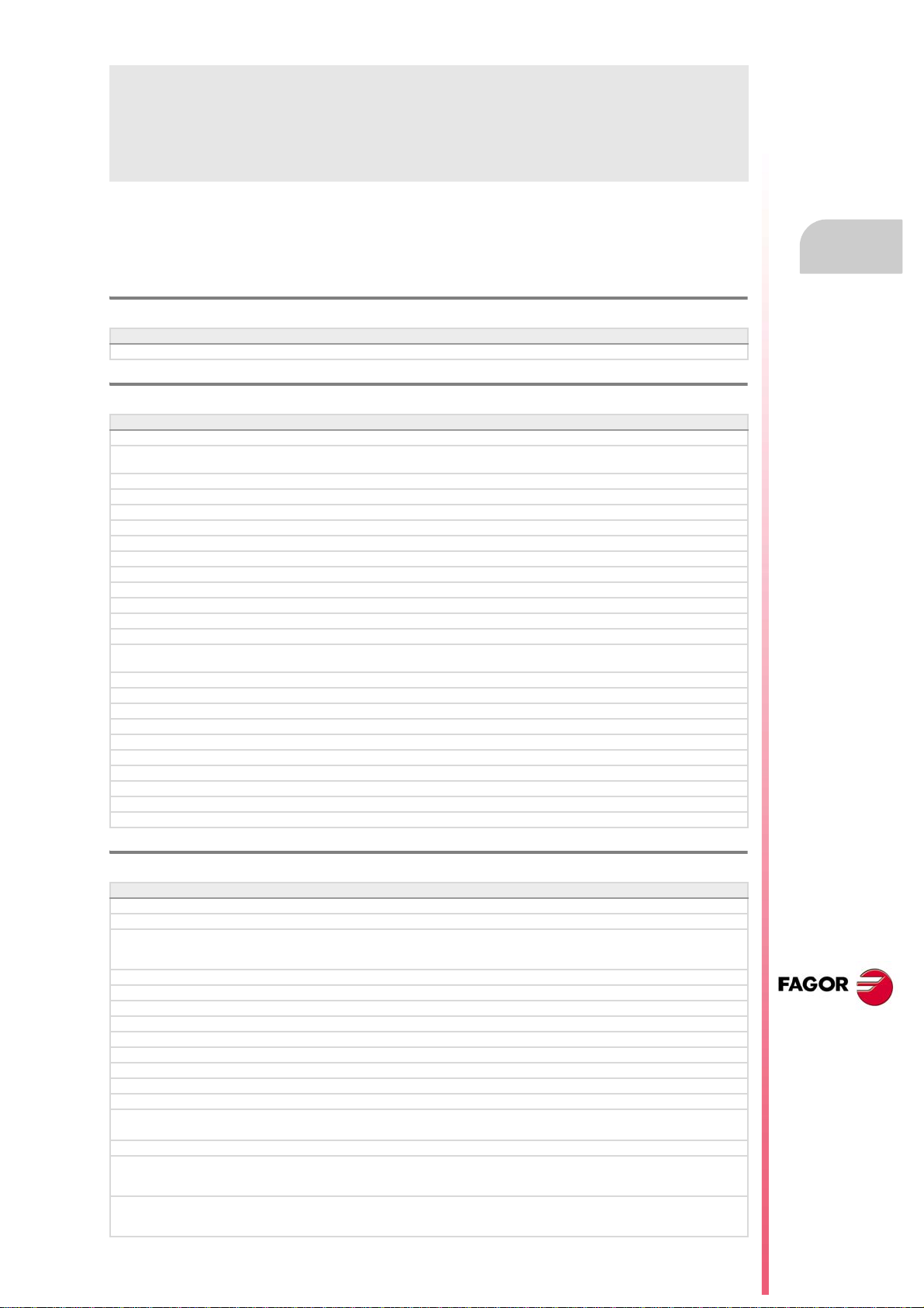
SOFTWARE OPTIONS.
Bear in mind that some of the features described in this manual depend on the software options that are
installed. The information of the following table is informative only; when purchasing the software options,
only the information provided in the ordering handbook is valid.
-BL- model -OL- model -M- model -T- model
Open system.
Access to the administrator mode.
Editing and simulation environment. - - - Standard Standard Standard
Number of execution channels 1 1 to 4 1 to 4 1 to 4
Number of axes 3 to 7 3 to 28 3 to 28 3 to 28
Number of spindles 1 1 to 4 1 to 4 1 to 4
Number of tool magazines 1 1 to 4 1 to 4 1 to 4
Number of interpolated axes (maximum) 4 28 - - - - - -
Limited to 4 interpolated axes Option Option Option Option
IEC 61131 language Option Option - - - - - -
HD graphics - - - Option Option Option
Conversational IIP - - - - - - Option Option
Non-Fagor digital drive Option Option - - - - - -
Tool radius compensation Option Option Standard Standard
"C" axis Option Option Standard Standard
Dynamic RTCP Option Option - - - Option
HSSA machining system. Option Option Standard Standard
Probing canned cycles - - - - - - Option Standard
Profile editor - - - - - - Standard Standard
Drilling ISO cycles for the OL model.
(G80, G81, G82, G83).
Tandem axes - - - Option - - - Option
Synchronism and cams Option Option - - - - - -
Tangential control Option Option - - - Standard
Volumetric compensation (up to 10 m³). Option Option Option Option
Volumetric compensation (more than 10 m³). Option Option Option Option
- - - Option - - - - - -
- - - Option - - - - - -
CNC 8070
(REF: 1309)
·10·
Page 11
Operating manual
DECLARATION OF CONFORMITY
The manufacturer:
Fagor Automation S. Coop.
Barrio de San Andrés Nº 19, C.P.20500, Mondragón -Guipúzcoa- (Spain).
Declares:
The manufacturer declares under their exclusive responsibility the conformity of the product:
8070 CNC
Consisting of the following modules and accessories:
8070-BL-ICU, 8070-OL-ICU
8070-BL-MCU, 8070-OL-MCU , 8070-OL-MCU-PCI
MONITOR-LCD-10K, MONITOR-LCD-15, MONITOR-SVGA-15
HORIZONTAL-KEYB, VERTICAL-KEYB, OP-PANEL
BATTERY, MOUSE UNIT
Remote Modules RIOW, RIO5, RIO70, RCS-S.
Note.Some additional characters may follow the model references indicated above. They all comply with the
directives listed here. However, compliance may be verified on the label of the unit itself.
Referred to by this declaration with following directives:
Low-voltage regulations.
IEC 60204-1:2005/A1:2008 Electrical equipment on machines. Part1. General requirements.
Regulation on electromagnetic compatibility.
EN 61131-2: 2007 PLC. Part 2. Equipment requirements and tests.
According to the European Community Directives 2006/95/EC on Low Voltage and 2004/108/EC
on Electromagnetic Compatibility and their updates.
In Mondragón, September 1st, 2013.
CNC 8070
(REF: 1309)
·11·
Page 12

Page 13
Operating manual
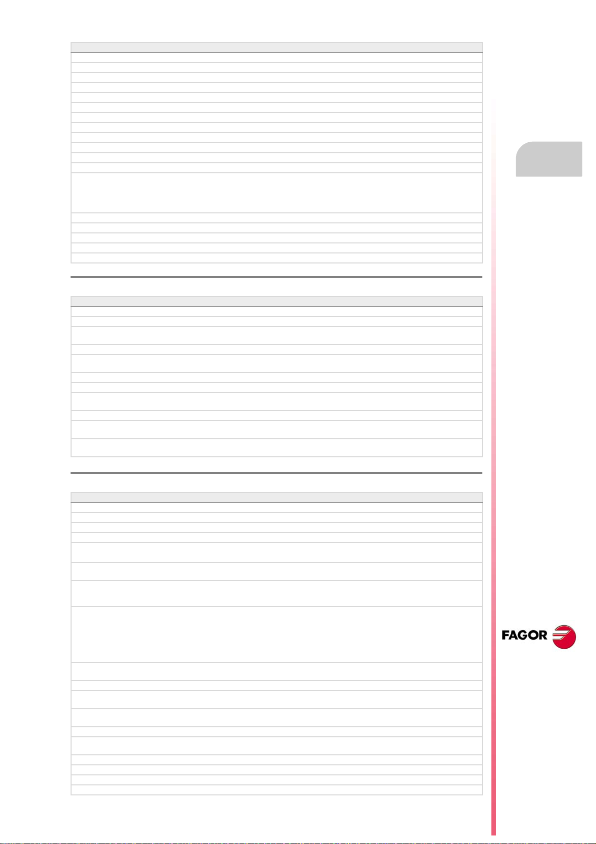
VERSION HISTORY
Here is a list of the features added to each manual reference. Each manual reference is valid for the indicated
software version and newer versions.
Ref. 0201
Software V01.00
First version. Milling model.
Ref. 0212
Software V01.10
New repositioning feedrate after tool inspection. • Machine parameter: REPOSFEED.
New treatment of the JOG keys. Different keys to select the axis and the
direction.
Know the dimensions of the kinematics on an axis. • Variable: (V.)A.HEADOF.xn
Keyboard simulation from the PLC. • Variable: (V.)G.KEY
Jog mode. Tool calibration with or without probe.
Jog mode. Automatic loading of zero offsets table.
Jog mode. Programming of feedrate "F" and spindle speed "S".
MDI mode. Block syntax check.
Utilities mode. Define protection passwords.
Block search. Define the first block.
Improved tool table.
Axis selection/deselection to move it with a handwheel.
Simulate the theoretical path.
Confirm the execution of a program pressing the [START] key in a mode other
than automatic.
General scaling factor. • New instruction, #SCALE.
Probe selection. • New instruction, #SELECT PROBE.
Probing canned cycles. • New instruction, #PROBE.
Programming of warnings. • New instruction, #WARNING.
Block repetition. • New instruction, #RPT.
Know the active general scaling factor. • Variable: (V.)G.SCALE
Knowing which is the active probe. • Variable: (V.)G.ACTIVPROBE
Improved programming of high speed machining. • #HSC instruction.
Improved programming of axis swapping. • Instructions #SET, #CALL, #FREE, #RENAME.
The number of macros in a program is now limited to 50. • Macros.
• Machine parameter: JOGKEYDEF.
Ref. 0501
Software V02.01
Windows XP operating system.
Emergency shutdown with battery (central unit PC104).
Multi-channel system, up to 4 channels. Swapping of axes and spindles,
communication and synchronization between channels, common arithmetic
parameters, access variables by channel, etc.
Multi-spindle system, up to 4 spindles.
Tool management with up to 4 magazines.
New languages (Basque and Portuguese). • Machine parameter: LANGUAGE.
Placing the vertical softkeys on the left or on the right. • Machine parameter: VMENU.
Tool radius compensation mode (G136/G137) by default • Machine parameter: IRCOMP.
OEM generic machine parameters. • Machine parameter: MTBPAR.
Reading Sercos variables from the CNC. • Machine parameter: DRIVEVAR.
Electronic-cam editor. • Machine parameter: CAM.
New behavior for rotary axes.
The "(V.).TM.MZWAIT " variable is not necessary in the subroutine associated
with M06.
Know the software version. • Variable: (V.)G.SOFTWARE
Variables related to loop adjustment. Gain setting via PLC. • Variables:
Variables related to loop adjustment. Position increment and sampling period. • Variables:
• Subroutine associated with M6.
• Variable: (V.).TM.MZWAIT
(V.)A.PLCFFGAIN.xn (V.)A.PLCACFGAIN.xn
(V.)A.PLCPROGAIN.xn
(V.)A.POSINC.xn (V.)A.TPOSINC.xn
(V.)A.PREVPOSINC.xn
CNC 8070
(REF: 1309)
·13·
Page 14

Operating manual
Software V02.01
Variables related to loop adjustment. Fine adjustment of feedrate, acceleration
and jerk.
Variables related to the feedback inputs. • Variables:
Optimize the reading and writing of variables from the PLC. Only the access
to the following variables will be asynchronous.
• The tool variables will be read asynchronously when the tool is neither the
active one nor in the magazine.
• The tool variables will be written asynchronously whether the tool is the
active one or not.
• The variables referred to local arithmetic parameters of the active levels
will be read and written asynchronously.
Spindle parking and unparking. • Instructions #PARK, #UNPARK.
Tool radius compensation.
• Behavior of the beginning and end of tool radius compensation when not
programming a movement.
• Changing the type of radius compensation while machining.
Via program, loading a tool in a specific magazine position.
Programming of modal subroutines. • New instruction, #MCALL.
Executing a block in a channel. • New instruction, #EXBLK.
Programming the number of repetitions in the block. • NR command.
Direct resolution of 2D and 3D pockets without requiring a softkey.
Simulating a canned cycle of the editor separately.
Importing DXF files from the program editor or from the profile editor.
Importing programs of the 8055/8055i CNC from the program editor.
Use a softkey to select the repositioning of the spindle after tool inspection.
Backup-restore utility.
Improved profile editor.
Assistance in the program editor. Contextual programming assistance.
• When programming "#", it shows the list of instructions.
• When programming "$", it shows the list of instructions.
• When programming "V.", it shows the list of variables.
Specific password for the machine parameters for kinematics.
Save the CAN configuration for testing it when starting up the system.
The diagnosis mode shows detailed information on the Sercos connection
(Type and version of the drive and motor connected to it).
It is possible to print all the information on the configuration from any section
of the diagnosis mode.
It is possible to simulate a cycle separately from the cycle editor.
Setup assistance. Oscilloscope, Bode diagram, circularity test.
• Variables:
(V.)A.FEED.xn (V.)A.TFEED.xn
(V.)A.ACCEL.xn (V.)A.TACCEL.xn
(V.)A.JERK.xn (V.)A.TJERK.xn
(V.)A.COUNTER.xn (V.)A.COUNTERST.xn
(V.)A.ASINUS.xn (V.)A.BSINUS.xn
• Reading and writing of variables from the PLC.
CNC 8070
(REF: 1309)
Ref. 0504
Software V02.03
New values of machine parameter SERPOWSE for the "Sercos II" board. • Machine parameters: SERPOWSE.
The simulated axes are ignored regarding the validation code.
Electronic cam programming (real coordinates). • New instruction, #CAM.
Synchronization of independent axis (real coordinates). • New instruction, #FOLLOW.
Movement of the independent axis. • New instruction, #MOVE.
DDSSetup mode.
G31. Temporary polar origin shift to the center of interpolation. • G31 function.
G112. Change the drive's parameter set. • G112 function.
Ref. 0509
Software V03.00
Lathe model. Machining canned cycles, lathe tool calibration, variables to
consult the geometry of lathe tools, etc.
Incline axis.
Permit using the G95 function in jog mode. • Machine parameter: FPRMAN.
Lathe model. Select graphics configuration. • Machine parameter: GRAPHTYPE.
Lathe model. Select axis configuration. • Machine parameter: GEOCONFIG.
Select the set of parameters for synchronization. • Machine parameter: SYNCSET.
"C" axis maintained. • Machine parameter: PERCAX.
Magazine-less system.
Ground tools for a turret magazine.
Variable to read the accumulated PLC offset. • Variable: (V.)[ch].A.ACTPLCOF.xn
Variable to obtain a linear estimation of the following error. • Variable: (V.)[ch].A.FLWEST.xn
Variables to read the instant value of feed-forward or AC-forward. • Variables:
Variable to know the line number of the file being executed. • Variable: (V.)[ch].G.LINEN
Variable to know what kind of cycle is active. • Variable: (V.)[ch].G.CYCLETYPEON
Variable to know the tool orientation. • Variable: (V.)[ch].G.TOOLDIR
(V.)[ch].A.ACTFFW.xn (V.)[ch].A.ACTACF.xn
·14·
Page 15
Operating manual
Software V03.00
Variable to know whether the HSC mode is active or not. • Variable: (V.)[ch].G.HSC
Variable to know the theoretical feedrate on 3D path. • Variable: (V.)[ch].G.F3D
Variable to know the number of the warning being displayed. • Variable: (V.)[ch].G.CNCWARNING
The variable (V.)G.CNCERR is now per channel. • Variable: (V.)G.CNCERR
Select the type of loop, open or closed, for the spindle. • New instruction, #SERVO.
Spindle synchronization. • New instruction, #SYNC.
Spindle synchronization. • New instruction, #TSYNC.
Spindle synchronization. • New instruction, #UNSYNC.
Select milling cycles at a lathe model. • New instruction, #MILLCY.
Select turning cycles at a milling model. • New instruction, #LATHECY.
Define a kinematics when activating the C axis. • #CYL instruction.
Define a kinematics when activating the C axis. • #FACE instruction.
Improved coordinate transformation (#CS/#ACS).
• Keep the part zero when deactivating the transformation.
• Working with 45º spindles. Select between the two choices.
• Keep the rotation of the plane axes with MODE 6.
G33. New parameter (Q1) to define the entry angle. • G33 function.
G63. Tool inspection is possible during rigid tapping. • G63 function.
Function G112 is not valid for the spindle. • G112 function.
New criteria when assuming a new master spindle in the channel.
Improved tool table.
• Instructions #CS, #ACS.
Ref. 0601
Software V03.01
Axis slaving. Configuring the default status of an axis slaving (coupling). • Machine parameters: LINKCANCEL.
Tool radius compensation. The way tool radius is canceled. • Machine parameters: COMPCANCEL.
Screen test on power-up, if any element is missing, it restores the relevant
backup.
Editing mode. Editing programs in the 8055 CNC language.
DDSSetup mode. Saving and loading the data of all the drives at the same
time.
Using the ":" character to program a comment in a part-program.
Variables. Geometry of the lathe tools.
Variables. Number of the tool in the claws of the changer arm. • Variables:
Automatic mode. It allows executing a program independently.
The instruction #EXEC does not issue an error if the channel is busy; the
instruction waits for the operation in progress to end.
The instruction #EXBLK does not issue an error if the channel is busy; the
instruction waits for the operation in progress to end.
(V.)TM.TOOLCH1[mz] (V.)TM.TOOLCH2[mz]
• #EXEC instruction.
• #EXBLK instruction.
Ref. 0606
Software V03.10
Feedrate. Maximum machining feedrate. • Machine parameter: MAXFEED.
Feedrate. Default machining feedrate when none has been programmed. • Machine parameter: DEFAULTFEED.
The user keys may be configured as jog keys. • Machine parameter: USERKEYDEF.
Disabling a keyboard or jog panel integrated into the CAN bus. • PLC mark: PANELOFF.
Handwheel with push-button. Selecting an axis sequentially for jogging it with
the handwheel.
New parameter to set whether or not the CNC sends the M, H, S functions to
the PLC during block search.
The CNC allows changing the spindle override during electronic threading
(G33) and in the threading canned cycles of the ·T· model (G86, G87 and their
equivalent of the cycle editor).
OEM machine parameters.
• Range of parameters that can be written from the part-program, from the
PLC or from the interface.
• Range of parameters affected by the change of units.
• Each parameter may have a different describing comment associated
with it.
Home search. New home searching method for spindles with home switch.
The spindle goes through the home switch twice.
The CNC displays the warnings generated at the drive.
M function table. New field to define whether the function is sent out to the PLC
or not during block search.
M function table. Each M function may have a different describing comment
associated with it.
General handwheel. The CNC may have several general handwheels.
General handwheel. A general handwheel can move several axes at the same
time.
Improvements in the looks of some softkeys of the editor.
Improvements in the looks of some softkeys of the graphics window.
Editing mode. Programming help files for OEM and global subroutines.
Editing mode. Help file with the list of available subroutines.
• PLC mark: NEXTMPGAXIS.
•
• Machine parameter: FUNPLC.
• Machine parameters:
THREADOVR, OVRFILTER.
• Field: MPLC.
• Field: COMMENT.
CNC 8070
(REF: 1309)
·15·
Page 16
Operating manual
Software V03.10
Editing mode. Improved contextual assistance.
Editing mode. New softkey for deactivating the contextual assistance.
Editing mode. Improvements in the looks of the softkeys.
The automatic mode offers a softkey for selecting the program that is being
edited.
In automatic and jog modes, the CNC shows the status of the _FEEDHOL
mark.
In automatic and jog modes, the CNC shows the status of the INHIBIT mark
of the axes and spindle.
Automatic mode. It shows information on all the spindles.
Jog mode. It shows information on all the spindles.
"Retrace" function.
Tangential control.
Tool table. New softkey for initializing the positions; T1 in position 1, T2 in
position 2, etc.
Tool table. New softkeys for copying and pasting the data of a tool offset.
The CNC checks whether the programmed turning direction (M3/M4) matches
the one preset in the tool table.
Generating the warranty registration report.
Hiding the window for errors and warnings.
M02/M30. There is no need to program M02 or M30 to end a part program. • Functions M02/M30.
Canceling the preset turning direction of a tool. • Variables: (V.)G.SPDLTURDIR
Change the maximum feedrate allowed in the channel from the PLC. • Variables: (V.)[ch].PLC.PLCG00FEED
Show the status of the emergency relay. • Variables: (V.)G.ERELAYST
HSC. New FAST mode. • #HSC instruction.
"C" axis. The #CYL instruction requires programming the radius. • #CYL instruction.
Improved block search.
Tool calibration.
• Manual calibration. When calibration is done, pressing [START] assumes
the new values.
• Semi-automatic calibration. Calibration of lathe tools.
• Semi-automatic calibration. When calibration is done, pressing [START]
assumes the new values.
• Automatic calibration. When calibration is done, the CNC assumes the
new values.
• PLC mark: _FEEDHOL.
• PLC mark: INHIBIT.
CNC 8070
(REF: 1309)
Ref. 0608
Software V03.11
Simulator Possibility to use the dongle (hardware key) in a network.
Line graphics. Improved resizing of the graphics on the screen.
"Retrace" function. Several improvements to the retrace function.
HSC. New command CORNER. • #HSC instruction.
The default value of some machine parameters is different for the CNC and
for the simulator installed on a PC.
G33. The override limitation is maintained while returning to the beginning of
the thread.
RTCP. Home search is now possible on the axes that are not involved in RTCP.
Abort the execution of the program and resume it somewhere else. • New instruction, #ABORT.
• G33 function.
Ref. 0704 / Ref. 0706
Software V03.13
Sign criteria for tool offsets (dimensions) and tool wear. • Machine parameters: TOOLOFSG.
Define the tool wear with incremental or absolute values. • Variables:
Variables V.TM.TOOLCH1[mz] / V.TM.TOOLCH2[mz] may be written from the
PLC.
MDI mode. Cancel the block being executed while keeping the machining
conditions.
Software V03.14
MCU and ICU central unit. battery powered RAM. Connecting handwheels to
the central unit. local I/O. Local feedback inputs. Loca probes.
Define whether the spindle is homed automatically with the first movement or
not.
The application may be restarted while turning the CNC off.
The task window may be accessed by clicking on the OEM icon (top left of the
status bar).
The channels may be accessed by clicking on the icons of the status bar).
The pages of an operating mode may be accessed by clicking on the mode
name (top right of the status bar).
The turning speed limitation (G192) is also applied when the spindle is working
at constant turning speed (G97)
(V.)TM.TOOLCH1[mz] (V.)TM.TOOLCH2[mz].
• G192 function.
·16·
Page 17
Operating manual
Ref. 0707
Software V03.15
Know the type of hardware. • Variable: (V.)G.HARDTYPE
Theoretical tool feedrate along the path. • Variable: (V.)[ch].G.PATHFEED
Every time the diagnosis mode is accessed, the CNC creates the files
SystemInfo.txt and SercosInfo.txt.
PLC errors may have an additional data file associated with them, same as
PLC messages.
User tables. The zero offset table shows the spindles that may be activated
as C axis.
Zero offsets for the C axis.
The CNC shows a warning when a channel is expecting a tool that is being
used in another channel.
Ref. 0709
Software V03.16
Tandem spindles.
Diagnosis mode. Monitoring of the temperature of the CPU, board and
enclosure.
The CNC uses the combined feedback to calculate the velocity command, but
it uses the direct feedback to calculate the compensations, circularity test, etc.
The CNC does not assume any kinematics on power-up. • Machine parameters: KINID
Machine parameters: KINID
The CNC allows modifying the override while threading if it detects that the
feed forward (parameter FFWTYPE) is not active in a gear or if the active feed
forward is lower than 90%
Ref. 0712
Software V03.17
C axis maintained after executing M02, M30 or after an emergency or reset. • Machine parameter: PERCAX.
Ref. 0801
Software V03.20
The CNC has a different MTB folder for each type of software installed; MTB_T
for lathe, MTB_M for mill and MTB_MC for motion control.
By default, the feedback alarms of the analog axes are activated.
Set change.
• For the CNC to assume the new parameter set, it must wait for the PLC
to receive the confirmation of one of the marks GEAR1 to GEAR4.
• The gear change concludes when the PLC receives the confirmation
signal AUXEND.
• Sercos spindle. The set change only affects the drive when it implies a
change of gear ratio.
• The CNC lets change the gear of the slave axis or spindle of a tandem.
Coordinate latching with the help of a probe or a digital input. • Variables:
PLC. The PLC program can have several mnemonic files (extension "plc").
PLC. When defining each PLC error, it is possible to select whether it opens
the emergency relay or not.
PLC. Grouping the additional information text files in a single file.
PLC. Contact (ladder) editor.
Status of the local probes. • Variables: (V.)G.PRBST1 (V.)G.PRBST2.
Axis synchronization. Managing a rotary axis as an infinite axis making it
possible to increase the feedback count of the axis indefinitely (wihout limits)
regardless of the value of the module.
Errors and warnings.
• From the errors and warnings, it is possible to access the errors solving
(troubleshooting) manual.
• CNC errors between 10000 and 20000 are reserved for the OEM so he
can create his own warning or error texts in different languages.
Show a warning and interrupt program execution. • New instruction, #WARNINGSTOP.
Electronic cam programming (theoretical coordinates). • New instruction, #TCAM.
Dynamic distribution of the machining operations between channels. • New instruction, #DINDIST.
The CNC can park the main axes.
The axes may be programmed using the "?" wild card that refers to the axis
position in the channel.
Functions G130 (percentage of acceleration) and G132 (percentage of jerk)
may be applied to the spindles.
Profile editor. Axes coordinated with auto-scale and name of the axes.
Profile editor. Zoom and movement of the graphics area via keyboard.
Profile editor. At the lathe model, the orientation of the axes is defined by
parameter GRAPHTYPE.
Edisimu mode. Inclined plane programming assistance.
(V.)[ch].A.LATCH1.xn (V.)[ch].A.LATCH2.xn
• Variables: (V.)[ch].A.ACCUDIST.xn
•Wild card "?".
• Functions G130 and G132.
• Machine parameter: GRAPHTYPE.
CNC 8070
(REF: 1309)
·17·
Page 18
CNC 8070
(REF: 1309)
Operating manual
Software V03.20
Edisimu mode. To simulate the program, when pressing the "START" softkey,
the CNC assumes the real configuration of the spindles of the channel and the
configuration of the machine parameters. The starting coordinates for
simulation will be the real coordinates that the CNC had on power-up.
Edisimu mode. New window for consulting the status of the subroutines,
canned cycles, block repetition and loops.
Edisimu mode. The "START" softkey saves the program being edited.
Automatic mode. New functions and instructions that cancel the retrace
function.
Automatic mode. New window for consulting the status of the subroutines,
canned cycles, block repetition and loops.
Automatic mode. The [START] key saves the program being edited.
Diagnosis mode. Generate the Fagor file for error diagnosis.
Tool table. When selecting an incremental wear, it is possible to define the
maximum increment possible; by default 0.5 mm (0.019685 inch).
Machine parameters tables. Import and export leadscrew compensation
tables.
Within a work mode, select the different pages in reverse order using the
[SHIFT] key.
Setup assistance. Bode.
Interface related variables.
Ref. 0809
Software V04.00 (it does not include the features of version V03.21)
Unicode.
New language (Chinese).
In the machine parameter table, an icon indicates which parameters are
involved in parameter matching.
Handwheels. There can now be up to 12 handwheels. • Machine parameter: NMPG.
The CNC applies module compensation throughout the entire revolution of the
axis.
Home search moving the axis to the reference point. • Machine parameter: POSINREF.
PLC. There can now be up to 1024 PLC messages. • PLC resources: MSG.
PLC. There can now be up to 1024 PLC errors. • PLC resources: ERR.
Handwheels. Inhibit the handwheels of the system. • PLC mark: INHIBITMPG1/INHIBITMPG12.
Cancel spindle synchronization after executing M02, M30 or after an error or
a reset.
Positioning a turret magazine whether there is a tool in the indicated position
or not.
A channel maintains its master spindle after executing M02, M30 or after an
emergency or a reset or restarting the CNC.
Force the change of gears and/or of the parameter set of a Sercos drive • Variable: (V.)A.SETGE.xn
Set a machine coordinate. • G174 function.
There can now be up to 99 zero offsets. • G159 function.
There can now be up to 100 synchronization marks. • Instructions #MEET, #WAIT and #SIGNAL.
Select a turret position. • #ROTATEMZ instructions.
Axis synchronization. Managing a rotary axis as an infinite axis making it
possible to increase the feedback count of the axis indefinitely (wihout limits)
regardless of the value of the module.
Variables. The variable (V.)[ch].E.PROGSELECT can be written via partprogram, PLC and interface. This variable can only be written with the value
of ·0·
Variables. The following variables are valid for the spindle. • Variables: (V.)[ch].A.MEAS.sn
Profile editor.
• Programming in Polar coordinates.
• Programming in incremental coordinates.
• Best zoom, display part zero and auto-zoom from the keyboard.
• Improved softkey menu.
Jog mode. New softkey to turn the CNC off.
Jog mode. In handwheel mode, next to each axis, the CNC indicates whether
that axis has an individual handwheel associated with it or not.
Jog mode. The screen shows the tool dimensions.
Automatic mode. The screen shows the tool dimensions.
Handwheels. The general handwheels can move axes with an associated
individual handwheel.
Handwheels. Number of pulses sent by the handwheel since the system was
started up.
Feed handwheel.
Diagnosis mode. View the error and warning history issued by the CNC.
• Machine parameter: MODCOMP.
• Instructions #SYNC and #TSYNC.
• #ROTATEMZ instructions.
• #MASTERinstruction.
• Variables: (V.)[ch].A.PREVACCUDIST.xn
• Variables: (V.)[ch].E.PROGSELECT
(V.)[ch].A.ATIPMEAS.sn
(V.)[ch].A.MEASOF.sn
(V.)[ch].A.MEASOK.sn
(V.)[ch].A.MEASIN.sn
• Variables: (V.)G.HANDP[hw]
·18·
Page 19
Operating manual
Software V04.00 (it does not include the features of version V03.21)
Edisimu mode and PLC mode.
• New hotkey to redo an operation.
• The editor shows the line number.
• The option "Find/replace" permits selecting the search direction, up or
down. New softkey to look for the text without replacing it.
• The editor adjusts the long blocks to the size of the window dividing the
block into several lines.
• The editor offers hotkeys [CTRL]+[+] and [CTRL]+[–] to increase or
decrease the size of the editor font. If the CNC has a mouse with a wheel,
the [CTRL] key combined with this wheel can also be used to increase
and decrease the size of the text font.
• In large files (more than 200 kB), the editor cancels the syntax coloring.
• In large files (more than 200 kB), the editor does not save the program
when changing blocks; the editor saves the program when the user has
not modified the program for about 5 seconds.
Edisimu mode.
• Comments having an asterisk (*) and programmed at the beginning of the
block allow to group blocks. Blocks programmed between these
comments will be grouped and may be expanded or shrunk the same way
as the cycles or profiles.
• Having the "Hide cycles/profiles" option active, when the cursor moves
over a hidden element, it expands automatically; when the cursor moves
out of the element, it shrinks again.
• The editor offers the [ALT]+[–] hotkey to expand y hide cycles, profiles and
grouped blocks. If the CNC has a mouse, click on the symbol located to
the right of the cycle, profile or group of blocks to expand them and hide
them.
• In large files (more than 200 kB), the editor does not hide the canned
cycles or the profiles.
PLC mode. New softkeys to sort the files that make up the PLC project.
Ref. 0811
Software V03.21 (features not included in version V04.00)
There can now be up to 1024 PLC messages. • PLC resources: MSG.
There can now be up to 1024 PLC errors. • PLC resources: ERR.
Ref. 0907
Software V04.01
The CNC turns the internal fan on and off as necessary. The CNC turns the
fan on when the temperature exceeds 50 ºC (122 ºF) and turns it off when it
gets under 45 ºC (113 ºF).
Communication with servos (axis and spindle) and inverters (spindle) through
the Mechatrolink bus, in Mlink-I (17 bytes) and Mlink-II (17 or 32 bytes) mode.
Define the maximum acceleration and jerk allowed on the tool path. • Machine parameters:
Variable to know the following error (lag) when feedback combination is active. • Variables:
Variable to know the position value of the first feedback when feedback
combination is active.
Diagnosis mode. Monitor battery voltage.
MAXACCEL, MAXJERK.
• Variables:
(V.)[ch].G.MAXACCEL (V.)[ch].G.MAXJERK
(V.)[ch].A.FLWE.xn (V.)[ch].A.FLWACT.xn
• Variable: (V.)[ch].A.POSMOTOR.xn
Ref. 1007
Software V04.10 (it does not include the features of version V04.02)
New languages (Russian and Czech). • Machine parameter: LANGUAGE.
Cancel the inclined plane on start-up. • Machine parameter: CSCANCEL.
Handwheels. Setting a negative resolution reverses the axis moving direction. • Machine parameter: MPGRESOL.
Activate the rapid traverse for the automatic mode while executing a program. • Machine parameters: RAPIDEN, FRAPIDEN.
• PLC mark: EXRAPID.
Maximum axis machining feedrate. • Machine parameter: MAXFEED.
Management of several keyboards. • Machine parameter: NKEYBD.
Configure the serial line as RS232, RS422 or RS485. • Machine parameter: RSTYPE.
Enable the HBLS handwheel. • Machine parameter: HBLS.
Selecting the type of PLC (IEC61131 or Fagor). • Machine parameter: PLCTYPE
RTCP. On tilting tables, rotate the part coordinate system when rotating the
table.
PLC. There are now 512 PLC timers. • PLC resources: Timers.
PLC. Management of spindle M functions (M3, M4 and M5) from the PLC. • PLC marks: PLCM3, PLCM4 and PLCM5.
New look for the interface.
MDI mode. The feedrate set in MDI/MDA mode will become the new feedrate
for the jog and automatic modes.
Jog mode. Set or activate a zero offset or fixture offset.
Jog mode. The screen shows an icon that represents the type of tool.
Automatic mode. The screen shows an icon that represents the type of tool.
• Kinematics TYPE9 through TYPE12.
CNC 8070
(REF: 1309)
·19·
Page 20
Operating manual
Software V04.10 (it does not include the features of version V04.02)
Editing mode. Use a template for part programs.
Utilities mode. Encrypt files.
The CNC allows eliminating certain errors by pressing the [ESC] key without
having to do a reset.
M functions with an associated subroutine.
The CNC admits function G174 for axes in DRO mode and spindles. • G174 function.
Detailed CNC status in jog mode. • Variable: (V.)[ch].G.CNCMANSTATUS
Detailed CNC status in automatic mode. • Variable: (V.)[ch].G.CNCAUTSTATUS
Know the axes selected for home search, repositioning, coordinate preset or
movement to a coordinate.
Know the current position of the main rotary axes of the kinematics (third
axis).
Know the target position of the main rotary axes of the kinematics (third axis). • Variable: (V.)[ch].G.TOOLORIT1
Cancel the name change for axes and spindles (#RENAME) after executing
M02 or M30, after a reset or at the beginning of a new part-program in the same
channel.
Graphic environment. Simulate the real path, but enlarging the error with
respect to the theoretical path.
• Variable: (V.)[ch].G.SELECTEDAXIS
• Variable: (V.)[ch].G.POSROTT
(V.)[ch].G.TOOLORIT2
• #RENAME instruction.
Ref. 1010
Software V04.02 (features not included in version V04.10)
New language (Russian). • Machine parameter: LANGUAGE.
Activate the rapid traverse for the automatic mode while executing a program. • Machine parameters: RAPIDEN, FRAPIDEN.
• PLC mark: EXRAPID.
Maximum axis machining feedrate. • Machine parameter: MAXFEED.
Management of several keyboards. • Machine parameter: NKEYBD.
Configure the serial line as RS232, RS422 or RS485. • Machine parameter: RSTYPE.
Synchronize spindles without forcing a set change. • Machine parameter: SYNCSET.
Mechatrolink. Activate the drive options. • Machine parameter: OPTION.
RTCP. On tilting tables, rotate the part coordinate system when rotating the
table.
MDI mode. The feedrate set in MDI/MDA mode will become the new feedrate
for the jog and automatic modes.
Jog mode. Set or activate a zero offset or fixture offset.
The CNC admits function G174 for axes in DRO mode and spindles. • G174 function.
Detailed CNC status in jog mode. • Variable: (V.)[ch].G.CNCMANSTATUS
Detailed CNC status in automatic mode. • Variable: (V.)[ch].G.CNCAUTSTATUS
Know the axes selected for home search, repositioning, coordinate preset or
movement to a coordinate.
Know the current position of the main rotary axes of the kinematics (third
axis).
Know the target position of the main rotary axes of the kinematics (third axis). • Variable: (V.)[ch].G.TOOLORIT1
Know the status of a cam. • Variable: (V.)G.CAMST[cam]
Modify the range of the slave axis when activating the cam. • Variable: (V.)G.CAM[cam][index]
Set 0% feedrate override via PLC. • Variable: (V.)[ch].PLC.FRO
Cancel the name change for axes and spindles (#RENAME) after executing
M02 or M30, after a reset or at the beginning of a new part-program in the same
channel.
Graphic environment. Simulate the real path, but enlarging the error with
respect to the theoretical path.
Edisimu mode. The simulation assumes the origins that are active for
execution.
• Kinematics TYPE9 through TYPE12.
• Variable: (V.)[ch].G.SELECTEDAXIS
• Variable: (V.)[ch].G.POSROTT
(V.)[ch].G.TOOLORIT2
• #RENAME instruction.
CNC 8070
(REF: 1309)
·20·
Ref. 1304
Software V04.20
Configure how to operate the CNC. Access work modes using hotkeys or from
the softkey menu.
Maximum safety limit for feedrate. • Machine parameter: FLIMIT.
Maximum safety speed limit. • Machine parameter: SLIMIT.
Interruption subroutines per channel. • Programming instructions: #REPOS.
There may be up to 30 OEM subroutines per channel now (G180-G189 /
G380-G399).
The OEM subroutines may be executed either in a non-modal (G180, G181,
etc) or in a modal way (MG180, MG181, etc).
Know the status of a cam. • Variable: (V.)G.CAMST[cam]
Modify the range of the slave axis when activating the cam. • Variable: (V.)G.CAM[cam][index]
Set 0% feedrate override via PLC. • Variable: (V.)[ch].PLC.FRO
Detailed CNC status in automatic mode. New values. • Variable: (V.)[ch].G.CNCAUTSTATUS
The CNC can execute programs of the 8055 MC and 8055 TC models made
up with conversational canned cycles including geometric assistance.
Tool table. Assign a name or text to any of the 4 "custom" parameters available
in each tool.
Operation with touch-screen model.
• Machine parameter: HMITYPE.
Page 21
Operating manual
Software V04.20
New tool inspection.
New HD graphics.
EDISIMU mode. Geometric help editor.
Jog mode. Tool calibration pages show the data of the tool to be calibrated.
MDI/MDA mode. The CNC can execute blocks when the execution of the
program is interrupted.
Automatic mode. Program simulation with the possibility to go into execution.
In this mode, it is possible to simulate a program, interrupt it at a point and start
execution from that point on.
Software V04.22
Automatic mode. Display the line number in execution.
Automatic mode. Display the line number where execution was interrupted.
Automatic mode. Resume the execution of a program from the block where it was canceled.
Automatic mode. While G95 active, the feedrate is shown in mm/turn.
Jog mode. While G95 active, the feedrate is shown in mm/turn.
User tables. Set the absolute zero offsets with a coarse part and a fine part.
User tables. Display the incremental zero offset (G158) in the zero offset table.
User tables. The zero offset table highlights in color the active offset, both absolute and incremental.
User tables. The clamp table highlights in color the active clamp.
User tables. Calculator assistance to set the data of the zero offset table.
User tables. Calculator assistance to set the data of the clamp offset table.
Tool tables. For the grooving and cut-off tool, the table assumes the values A=90, C=90 and Rp=0.
HD graphic environment. Select the simulation speed in the graphics window.
Software V04.24
Automatic mode. Cancel the execution and resume from another block while keeping the history.
Automatic mode. The CNC shows the percentage of the program that has been executed.
Software V04.25
Automatic mode. The "Main plane" simulation type does not send the M-H-S-T functions to the PLC.
Utilities mode. New backup-restore.
Ref. 1305
Software V04.26
Calculator. In jog or conversational mode, when calling the calculator with a field selected (F, S, etc), the calculator shows the value
of that field.
The CNC either shows or hides the softkey for toggling the display between mm and inches depending on the setting of machine
parameter MMINCHSOFTKEY.
Automatic mode. Programs with ".mod" extension may be modified when they are interrupted using "cancel and resume".
Ref. 1308
Software V04.26.10
Every time [START] is pressed, the CNC checks that the room temperature does not exceed 65 ºC (149 ºF) and, if it does, the CNC
does not let run the program and issues the corresponding error message.
Ref. 1309
Software V04.27
MDI/MDA mode. The [ENTER] key does not pop up block history.
Tool inspection allows accessing manual tool calibration.
CNC 8070
(REF: 1309)
·21·
Page 22

Page 23
Operating manual
SAFETY CONDITIONS
Read the following safety measures in order to prevent harming people or damage to this product and those
products connected to it. Fagor Automation shall not be held responsible of any physical damage or
defective unit resulting from not complying with these basic safety regulations.
Before start-up, verify that the machine that integrates this CNC meets the 89/392/CEE Directive.
PRECAUTIONS BEFORE CLEANING THE UNIT
If the CNC does not turn on when actuating the start-up switch, verify the connections.
Do not get into the inside of the unit. Only personnel authorized by Fagor Automation may manipulate the
Do not handle the connectors with the unit
connected to AC power.
inside of this unit.
Before manipulating the connectors (inputs/outputs, feedback, etc.)
make sure that the unit is not connected to AC power.
PRECAUTIONS DURING REPAIR
In case of a malfunction or failure, disconnect it and call the technical service.
Do not get into the inside of the unit. Only personnel authorized by Fagor Automation may manipulate the
inside of this unit.
Do not handle the connectors with the unit
connected to AC power.
Before manipulating the connectors (inputs/outputs, feedback, etc.)
make sure that the unit is not connected to AC power.
PRECAUTIONS AGAINST PERSONAL DAMAGE
Interconnection of modules. Use the connection cables provided with the unit.
Use proper cables. To prevent risks, use the proper cables for mains, Sercos and Bus
CAN recommended for this unit.
In order to avoid electrical shock at the central unit, use the proper
power (mains) cable. Use 3-wire power cables (one for ground
connection).
Avoid electrical overloads. In order to avoid electrical discharges and fire hazards, do not apply
electrical voltage outside the range selected on the rear panel of the
central unit.
Ground connection. In order to avoid electrical discharges, connect the ground terminals
of all the modules to the main ground terminal. Before connecting the
inputs and outputs of this unit, make sure that all the grounding
connections are properly made.
In order to avoid electrical shock, before turning the unit on verify that
the ground connection is properly made.
Do not work in humid environments. In order to avoid electrical discharges, always work under 90% of
relative humidity (non-condensing) and 45 ºC (113 ºF).
Do not work in explosive environments. In order to avoid risks or damages, do no work in explosive
environments.
CNC 8070
(REF: 1309)
·23·
Page 24
Operating manual
PRECAUTIONS AGAINST PRODUCT DAMAGE
Working environment. This unit is ready to be used in industr ial environments complying with
the directives and regulations effective in the European Community.
Fagor Automation shall not be held responsible for any damage
suffered or caused by the CNC when installed in other environments
(residential or homes).
Install the unit in the right place. It is recommended, whenever possible, to install the CNC away from
coolants, chemical product, blows, etc. that could damage it.
This unit complies with the European directives on electromagnetic
compatibility. Nevertheless, it is recommended to keep it away from
sources of electromagnetic disturbance such as:
Powerful loads connected to the same AC power line as this
equipment.
Nearby portable transmitters (Radio-telephones, Ham radio
transmitters).
Nearby radio/TV transmitters.
Nearby arc welding machines.
Nearby High Voltage power lines.
Enclosures. The manufacturer is responsible of assuring that the enclosure
involving the equipment meets all the currently effective directives of
the European Community.
Avoid disturbances coming from the
machine.
Use the proper power supply. Use an external regulated 24 Vdc power supply for the keyboard and
Grounding of the power supply. The zero volt point of the external power supply must be connected
Analog inputs and outputs connection. Use shielded cables connecting all their meshes to the corresponding
Ambient conditions. The storage temperature must be between +5 ºC and +45 ºC (41 ºF
Central unit enclosure. Make sure that the needed gap is kept between the central unit and
Main AC power switch. This switch must be easy to access and at a distance between 0.7 and
The machine must have all the interference generating elements
(relay coils, contactors, motors, etc.) uncoupled.
the remote modules.
to the main ground point of the machine.
pin.
and 113 ºF).
The storage temperature must be between -25 ºC and 70 ºC (-13 ºF
and 158 ºF).
each wall of the enclosure.
Use a DC fan to improve enclosure ventilation.
1.7 m (2.3 and 5.6 ft) off the floor.
CNC 8070
(REF: 1309)
·24·
PROTECTIONS OF THE UNIT ITSELF
Remote modules. All the digital inputs and outputs have galvanic isolation via
optocouplers between the CNC circuitry and the outside.
Page 25
Operating manual
i
SAFETY SYMBOLS
Symbols that may appear on the manual.
Danger or prohibition symbol.
It indicates actions or operations that may hurt people or damage products.
Warning symbol.
It indicates situations that certain operations could cause and the suggested actions to prevent them.
Obligation symbol.
It indicates actions and operations that must be carried out.
Information symbol.
It indicates notes, warnings and advises.
Symbols that the product may carry.
Ground protection symbol.
It indicates that that point must be under voltage.
CNC 8070
(REF: 1309)
·25·
Page 26

Page 27
Operating manual
WARRANTY TERMS
INITIAL WARRANTY
All products manufactured or marketed by FAGOR carry a 12-month warranty for the end user which could
be controlled by the our service network by means of the warranty control system established by FAGOR
for this purpose.
In order to prevent the possibility of having the time period from the time a product leaves our warehouse
until the end user actually receives it run against this 12-month warranty, FAGOR has set up a warranty
control system based on having the manufacturer or agent inform FAGOR of the destination, identification
and on-machine installation date, by filling out the document accompanying each FAGOR product in the
warranty envelope. This system, besides assuring a full year of warranty to the end user, enables our service
network to know about FAGOR equipment coming from other countries into their area of responsibility.
The warranty starting date will be the one appearing as the installation date on the above mentioned
document. FAGOR offers the manufacturer or agent 12 months to sell and install the product. This means
that the warranty starting date may be up to one year after the product has left our warehouse so long as
the warranty control sheet has been sent back to us. This translates into the extension of warranty period
to two years since the product left our warehouse. If this sheet has not been sent to us, the warranty period
ends 15 months from when the product left our warehouse.
This warranty covers all costs of material and labour involved in repairs at FAGOR carried out to correct
malfunctions in the equipment. FAGOR undertakes to repair or replace their products within the period from
the moment manufacture begins until 8 years after the date on which it disappears from the catalogue.
It is entirely up to FAGOR to determine whether the repair is or not under warranty.
EXCLUDING CLAUSES
Repairs will be carried out on our premises. Therefore, all expenses incurred as a result of trips made by
technical personnel to carry out equipment repairs, despite these being within the above-mentioned period
of warranty, are not covered by the warranty.
Said warranty will be applied whenever the equipment has been installed in accordance with instructions,
has not be mistreated, has not been damaged by accident or by negligence and has not been tampered
with by personnel not authorised by FAGOR. If, once servicing or repairs have been made, the cause of
the malfunction cannot be attributed to said elements, the customer is obliged to cover the expenses
incurred, in accordance with the tariffs in force.
Other warranties, implicit or explicit, are not covered and FAGOR AUTOMATION cannot be held responsible
for other damages which may occur.
CNC 8070
(REF: 1309)
·27·
Page 28
Operating manual
WARRANTY ON REPAIRS
In a similar way to the initial warranty, FAGOR offers a warranty on standard repairs according to the
following conditions:
PERIOD 12 months.
CONCEPT Covers parts and labor for repairs (or replacements) at the
network's own facilities.
EXCLUDING CLAUSES The same as those applied regarding the chapter on initial
warranty. If the repair is carried out within the warranty period, the
warranty extension has no effect.
When the customer does not choose the standard repair and just the faulty material has been replaced,
the warranty will cover just the replaced parts or components within 12 months.
For sold parts the warranty is 12 moths length.
SERVICE CONTRACTS
The SERVICE CONTRACT is available for the distributor or manufacturer who buys and installs our CNC
systems.
CNC 8070
(REF: 1309)
·28·
Page 29

Operating manual
MATERIAL RETURNING TERMS
When sending the central nit or the remote modules, pack them in its original package and packaging
material. If the original packaging material is not available, pack it as follows:
1 Get a cardboard box whose three inside dimensions are at least 15 cm (6 inches) larger than those
of the unit. The cardboard being used to make the box must have a resistance of 170 Kg (375 lb.).
2 Attach a label indicating the owner of the unit, person to contact, type of unit and serial number. In case
of malfunction also indicate symptom and a brief description of the problem.
3 Wrap the unit in a polyethylene roll or similar material to protect it. When sending a central unit with
monitor, protect especially the screen.
4 Pad the unit inside the cardboard box with poly-utherane foam on all sides.
5 Seal the cardboard box with packing tape or industrial staples.
CNC 8070
(REF: 1309)
·29·
Page 30

Page 31

Operating manual
CNC MAINTENANCE
CLEANING
The accumulated dirt inside the unit may act as a screen preventing the proper dissipation of the heat
generated by the internal circuitry which could result in a harmful overheating of the unit and, consequently,
possible malfunctions. Accumulated dirt can sometimes act as an electrical conductor and short-circuit the
internal circuitry, especially under high humidity conditions.
To clean the operator panel and the monitor, a smooth cloth should be used which has been dipped into
de-ionized water and /or non abrasive dish-washer soap (liquid, never powder) or 75º alcohol. Do not use
highly compressed air to clean the unit because it could generate electrostatic discharges.
The plastics used on the front panel are resistant to grease and mineral oils, bases and bleach, dissolved
detergents and alcohol. Avoid the action of solvents such as chlorine hydrocarbons, venzole, esters and
ether which can damage the plastics used to make the unit’s front panel.
PRECAUTIONS BEFORE CLEANING THE UNIT
Fagor Automation shall not be held responsible for any material or physical damage derived from the
violation of these basic safety requirements.
• Do not handle the connectors with the unit connected to AC power. Before handling these connectors
(I/O, feedback, etc.), make sure that the unit is not connected to main AC power.
• Do not get into the inside of the unit. Only personnel authorized by Fagor Automation may manipulate
the inside of this unit.
• If the CNC does not turn on when actuating the start-up switch, verify the connections.
CNC 8070
(REF: 1309)
·31·
Page 32

Page 33

DESCRIPTION OF THE KEYS
F1 F2 F3 F4 F5 F6 F7
F8
F9
F10
F11
F12
HELP
?
NEXT
FOCUS
BACK
F1
NEXT
FOCUS
BACK
HELP
?
1.1 Monitor LCD-15.
1
Function keys.
Softkeys.
Keys F1 through F12 select the options of the
softkey menus.
Browsing keys.
NEXT key.
Configurable key that can carry out one of the
following actions.
• Access the various screens of the active
work mode sequentially, pressing [SHIFT] at
the same time inverts the sequence. In the
PLC mode, it switches between the various
active services.
• Sequentially access the different channels.
• The horizontal softkey menu shows the
available screens and the vertical menu
shows the available channels.
FOCUS key.
It is used to switch between the different windows
of the screen.
Help key.
BACK key.
On the horizontal softkey menu, it lets you go up
from the softkey sub-menu to the previous level
from where that menu was accessed.
HELP key.
It accesses the CNC's system help.
CNC 8070
(REF: 1309)
·33·
Page 34

1.
F8
F9
F10
F11
F12
HELP
?
NEXT
ABCDEF
GH I JKL
MNÑOPQ
RSTUV
W
XYZ
INS
F1 F2 F3 F4 F5 F6 F7
MANUAL MDIAUTO EDIT TA BLES UTILITIESTOOLS
7 8 9
4 5 6
1 2 3
_
0
.
+
*
=
/
ENTER
RECALL
MAIN
MENU
CUSTOM
FOCUS
ZERO
SINGLE
RESET
_
+
X Y Z
4 5 6
_
+
ESC
CTRL
ALT
CAPS
#$
,
[]
;
HOME
END
SHIFT
CALC
DELETESPACE
BACK
SPACE
10000
1000
100
10
1
100
10
1
jog
200
190
180
170
160
150
140
130
120
110
1009080
70
60
50
40
30
20
10
4
2
0
FEED
F1
NEXT
FOCUS
HELP
?
MAIN
MENU
AUTO
MANUAL
EDIT
MDI
TABLES
TOOLS
UTILITIES
CUSTOM
Operating manual
1.2 Monitor LCD-10K.
Monitor LCD-10K.
DESCRIPTION OF THE KEYS
CNC 8070
(REF: 1309)
Function keys.
Softkeys.
Keys F1 through F12 select the options of the
softkey menus.
Browsing keys.
NEXT key.
Configurable key that can carry out one of the
following actions.
• Access the various screens of the active
work mode sequentially, pressing [SHIFT] at
the same time inverts the sequence. In the
PLC mode, it switches between the various
active services.
• Sequentially access the different channels.
• The horizontal softkey menu shows the
available screens and the vertical menu
shows the available channels.
FOCUS key.
It is used to switch between the different windows
of the screen.
Help key.
HELP key.
It accesses the CNC's system help.
Browsing keys.
Main menu.
Changing the state of an icon. In the MC/TC
mode, it toggles between the standard and the
auxiliary screens.
Work modes.
Automatic mode.
Manual (jog) mode.
EDISIMU mode.
MDI/MDA mode.
User tables (zero offsets, fixtures and arithmetic
parameters).
Tool and magazine table.
Utilities mode.
After accessing the work mode, these keys may be used
to access the various screens of the active work mode
sequentially, pressing [SHIFT] at the same time inverts the
sequence.
Configurable mode.
OEM-configurable key that can carry out one of
the following actions.
• Access a CNC work mode.
• Execute an application.
• Access the operating system.
• Carry out no function at all.
·34·
Page 35

Operating manual
ENDHOME
SHIFT
CAPS
ALT
BACK
SPACE
DELETE
INS
ESC
ENTER
RECALL
CALC
X+ 7+
X- 7-
X 7
_
+
10000
1000
100
10
1
100
10
1
jog
200
190
180
170
160
150
140
130
120
110
1009080
70
60
50
40
30
20
10
4
2
0
FEED
RESET
SINGLE
ZERO
_
+
Keys to move the cursor.
The arrow keys move the cursor one position
to the left, right, up or down.
The previous-page or next-page keys show
the previous or next page at the partprogram or PLC program editor.
The home and end keys move the cursor the
beginning or end of the line.
The tab key moves the cursor to the next field
of the active menu.
Editing keys.
Shift.
Hold this key down to write upper case
letters. When combining this key with a
cursor moving key, it selects the text the
cursor slides on.
Shift lock.
It toggles between uppercase and
lowercase letters.
ASCII characters.
Hold this key down and key in the
corresponding ASCII code.
Delete.
Delete.
Insert or overwrite.
Escape key, to cancel the current action
without assuming the changes.
Key to validate commands, data and
program blocks of the editor.
Recover data.
While the Teach-in mode is active, this key
enters the axes and their current position
into the block.
When selecting a profile or conversational
canned cycle in the part-program, the key
accesses either the profile editor or canned
cycle editor accordingly.
Calculator.
Feed selectors.
Execution keys.
Cycle start key (START).
Execute the selected program in automatic
mode, a block in MDI/MDA mode, etc.
Cycle stop key (STOP).
Interrupt the execution of the CNC.
Reset key.
It initializes the system setting the initial
conditions as defined by machine parameters.
Single-block execution mode.
When selecting the "single block" execution
mode, the program simulation will be interrupted
at the end of each block.
Home search.
Spindle control.
Start the spindle clockwise.
Stop the spindle.
Start the spindle counteclockwise.
To vary the spindle speed percentually.
Spindle orientation.
Sector for the type of jog;
continuous / incremental jog or
handwheels.
In handwheel mode, it selects the
multiplying factor for the
handwheel pulses (x1, x10 o
x100).
In incremental mode, it selects
the incremental value of the axis
movements.
Selector of percentage of
feedrate override, between 0%
and 200%, for jog and automatic
movements.
1.
Monitor LCD-10K.
DESCRIPTION OF THE KEYS
Jog keyboard for jogging the axes.
Keys to select axes and jog them in the
positive direction.
Keys to select axes and jog them in the
negative direction.
Keys to select the axes and keys to select the
jogging direction. Both keys (axis and
direction) must be pressed to jog the axis.
Rapid key. When pressing this key while
moving an axis, the CNC applies the rapid
feedrate.
CNC 8070
(REF: 1309)
·35·
Page 36

1.
Q W E R T Y U I O P
S D F G H J K L ÑA
ZXCVBNM
ALTGRALTCTRL
CAPS INS
DEL
MAIN
MENU
END
HOME
789
456
123
_
0
.
+
*
=
/
CUSTOM
RECALL ENTER
,.-
{}
^
ESC
SHIFTSHIFT
<
SPACE
UTILITIESTO OLSTABLESEDITMANUALAUTO
MDI
MAIN
MENU
AUTO
MANUAL
EDIT
MDI
TABLES
TOOLS
UTILITIES
CUSTOM
ENDHOME
SHIFT
CAPS
ALTGR
ALT
DEL
INS
ESC
ENTER
RECALL
Operating manual
1.3 HORIZONTAL KEYB / HORIZONTAL KEYB + MOUSE.
Browsing keys.
Main menu.
Changing the state of an icon. In the MC/TC
mode, it toggles between the standard and the
auxiliary screens.
DESCRIPTION OF THE KEYS
Work modes.
Automatic mode.
Manual (jog) mode.
EDISIMU mode.
MDI/MDA mode.
HORIZONTAL KEYB / HORIZONTAL KEYB + MOUSE.
After accessing the work mode, these keys may be used
to access the various screens of the active work mode
sequentially, pressing [SHIFT] at the same time inverts the
sequence.
User tables (zero offsets, fixtures and arithmetic
parameters).
Tool and magazine table.
Utilities mode.
Configurable mode.
OEM-configurable key that can carry out one of
the following actions.
• Access a CNC work mode.
• Execute an application.
• Access the operating system.
• Carry out no function at all.
Editing keys.
Shift.
Hold this key down to write upper case
letters. When combining this key with a
cursor moving key, it selects the text the
cursor slides on.
Shift lock.
It toggles between uppercase and
lowercase letters.
Alternate characters.
Hold this key down to access the alternate
character set of the keyboard.
ASCII characters.
Hold this key down and key in the
corresponding ASCII code.
Delete.
Delete.
Insert or overwrite.
Escape key, to cancel the current action
without assuming the changes.
Key to validate commands, data and
program blocks of the editor.
Recover data.
While the Teach-in mode is active, this key
enters the axes and their current position
into the block.
When selecting a profile or conversational
canned cycle in the part-program, the key
accesses either the profile editor or canned
cycle editor accordingly.
Keys to move the cursor.
The arrow keys move the cursor one position
to the left, right, up or down.
CNC 8070
The previous-page or next-page keys show
the previous or next page at the partprogram or PLC program editor.
The home and end keys move the cursor the
(REF: 1309)
·36·
beginning or end of the line.
The tab key moves the cursor to the next field
of the active menu.
Page 37

Operating manual
END
HOME
789
456
123
_
0
.
+
*
=
/
A B C D E F
G H I J K L
M N Ñ O P Q
R S T U V W
X Y Z
INS DEL
SPACE
ENTER
RECALL
ESC
ALT
CAPS
SHIFT
CTRL
MDI
EDITMANUALAUTO
MAIN
MENU
CUSTOM
TABLES TOOLS UTILITIES
MAIN
MENU
AUTO
MANUAL
EDIT
MDI
TABLES
TOOLS
UTILITIES
CUSTOM
ENDHOME
SHIFT
CAPS
ALT
DEL
INS
ESC
ENTER
RECALL
1.4 VERTICAL KEYB / VERTICAL KEYB + MOUSE.
Keys to move the cursor.
The arrow keys move the cursor one position
to the left, right, up or down.
The previous-page or next-page keys show
the previous or next page at the partprogram or PLC program editor.
The home and end keys move the cursor the
beginning or end of the line.
The tab key moves the cursor to the next field
of the active menu.
Editing keys.
Shift.
Hold this key down to write upper case
letters. When combining this key with a
cursor moving key, it selects the text the
cursor slides on.
Shift lock.
It toggles between uppercase and
lowercase letters.
ASCII characters.
Hold this key down and key in the
corresponding ASCII code.
Delete.
1.
DESCRIPTION OF THE KEYS
Browsing keys.
Work modes.
After accessing the work mode, these keys may be used
to access the various screens of the active work mode
sequentially, pressing [SHIFT] at the same time inverts the
sequence.
Main menu.
Changing the state of an icon. In the MC/TC
mode, it toggles between the standard and the
auxiliary screens.
Automatic mode.
Manual (jog) mode.
EDISIMU mode.
MDI/MDA mode.
User tables (zero offsets, fixtures and arithmetic
parameters).
Tool and magazine table.
Utilities mode.
Configurable mode.
OEM-configurable key that can carry out one of
the following actions.
• Access a CNC work mode.
• Execute an application.
• Access the operating system.
• Carry out no function at all.
Delete.
Insert or overwrite.
Escape key, to cancel the current action
without assuming the changes.
Key to validate commands, data and
program blocks of the editor.
Recover data.
While the Teach-in mode is active, this key
enters the axes and their current position
into the block.
When selecting a profile or conversational
canned cycle in the part-program, the key
accesses either the profile editor or canned
cycle editor accordingly.
VERTICAL KEYB / VERTICAL KEYB + MOUSE.
CNC 8070
(REF: 1309)
·37·
Page 38

1.
200
190
180
170
160
150
140
130
120
110
1009080
70
60
50
40
30
20
10
4
2
0
CNC
OFF
X+X-Y+ Z+
Y- Z-
4+ 5+ 6+
4- 5- 6-
7+ 7-
0
200
190
180
170
160
150
140
130
120
110
1009080
70
60
50
40
30
20
10
4
2
0
FEED
_
+
ZERO SING LE RESET
SPEED
10000
1000
100
10
1
100
10
1
jog
X+ 7+
X- 7-
X 7
_
+
10000
1000
100
10
1
100
10
1
jog
200
190
180
170
160
150
140
130
120
110
1009080
70
60
50
40
30
20
10
4
2
0
FEED
RESET
SINGLE
ZERO
_
+
200
190
180
170
160
150
140
130
120
110
1009080
70
60
50
40
30
20
10
4
2
0
SPEED
Operating manual
1.5 OP PANEL / OP PANEL + SPDL RATE.
Jog keyboard for jogging the axes.
Keys to select axes and jog them in the
positive direction.
Keys to select axes and jog them in the
negative direction.
DESCRIPTION OF THE KEYS
Keys to select the axes and keys to select the
jogging direction. Both keys (axis and
direction) must be pressed to jog the axis.
Rapid key. When pressing this key while
OP PANEL / OP PANEL + SPDL RATE.
moving an axis, the CNC applies the rapid
feedrate.
Feed selectors.
Sector for the type of jog;
continuous / incremental jog or
handwheels.
In handwheel mode, it selects the
multiplying factor for the
handwheel pulses (x1, x10 o
x100).
In incremental mode, it selects
the incremental value of the axis
movements.
Selector of percentage of
feedrate override, between 0%
and 200%, for jog and automatic
movements.
Spindle control.
Start the spindle clockwise.
Stop the spindle.
Start the spindle counteclockwise.
To vary the spindle speed percentually.
Spindle orientation.
Selector of percentage of spindle speed
override between 0% and 200%.
External devices.
The functions of these keys are defined by the machine
manufacturer and they allow controlling the various
devices of the machine (coolant, chip remover, etc.).
CNC 8070
(REF: 1309)
·38·
Execution keys.
Cycle start key (START).
Execute the selected program in automatic
mode, a block in MDI/MDA mode, etc.
Cycle stop key (STOP).
Interrupt the execution of the CNC.
Reset key.
It initializes the system setting the initial
conditions as defined by machine parameters.
Single-block execution mode.
When selecting the "single block" execution
mode, the program simulation will be interrupted
at the end of each block.
Home search.
Page 39

Operating manual
MAIN
MENU
AUTO
MANUAL
EDIT
MDI
TABLES
TOOLS
UTILITIES
BACK
FOCUS
FOCUS
RESET
SINGLE
RECALL
1.6 Keyboard shortcuts.
Operations at the interface.
[CTRL] + [W]
Minimize/Maximize the CNC.
[CTRL] + [J]
Show / hide the virtual operator panel.
[CTRL] + [M]
Show / hide the PLC message list.
[CTRL] + [O]
Show / hide the CNC message list.
[ALT] + [W]
Show / hide the window for errors and warnings.
[ALT] + [F4]
Turn the CNC off.
Work modes.
[CTRL] + [A]
To show the task window.
[CTRL] + [SHIFT] + [F1]
Main menu.
[CTRL] + [F6]
Automatic mode.
[CTRL] + [F7]
Manual (jog) mode.
[CTRL] + [F9]
EDISIMU mode.
[CTRL] + [F8]
MDI mode.
[CTRL] + [F10]
User tables.
[CTRL] + [F11]
Tool and magazine table.
[CTRL] + [F12]
Utilities mode.
[CTRL] + [K]
Calculator.
Browsing keys.
[CTRL]+[F1]
Previous menu.
[CTRL]+[F2]
Switch window.
[CTRL]+[F3]
Switch screens.
[ALT]+[B]
Two - co l or ke y.
Execution keys.
[CTRL]+[S]
Cycle start key (START).
[CTRL]+[P]
Cycle stop key (STOP).
[CTRL]+[R]
Reset key.
[CTRL]+[B]
Single-block execution mode.
The shortcuts for the [START] [STOP] and [RESET] keys
are only available when the CNC is installed as simulator
on a PC.
Program editor
[CTRL]+[C]
Copy the selected text.
[CTRL]+[X]
Cut the selected text.
[CTRL]+[V]
Paste the selected text.
[CTRL]+[Z]
Undo the last change.
[CTRL]+[Y]
Redo the selected text.
[CTRL]+[G]
Save the program / Recover the original program.
[CTRL]+[+]
Zoom in.
[CTRL]+[–]
Zoom out.
[ALT]+[–]
Hide or expand a cycle.
[CTRL]+[HOME]
Move the cursor to the beginning of the program.
[CTRL]+[END]
Move the program to the end of the program.
[CTRL]+[TAB]
Toggle between the editor and the error window.
[CTRL]+[F5]
[RECALL] key.
1.
Keyboard shortcuts.
DESCRIPTION OF THE KEYS
CNC 8070
(REF: 1309)
·39·
Page 40

1.
Operating manual
Keyboard shortcuts.
DESCRIPTION OF THE KEYS
CNC 8070
(REF: 1309)
·40·
Page 41

GENERAL CONCEPTS
2.1 Turning the CNC on and off
The way the CNC is turned on and off depends on the disk installed (read-only disk or not)
and on how it has been set by the machine manufacturer. However, the most common way
to do it is as follows.
Turning the CNC on
After powering up the unit, the operating system (Windows XP) will start up first. Then, and
depending on how the manufacturer has set it, the CNC application will either start up
automatically or will have to be initiated by clicking on the icon shown on the screen.
While starting up, it will display the initial standard CNC screen or the initial screen created
by the machine manufacturer for that purpose. Once the CNC is running, it will show the
screen for the work mode (automatic or jog) selected by the machine manufacturer.
2
Messages and options during the start-up.
When powering the CNC up, it informs on the contingencies that may be interesting.
Depending on what the CNC checks on power-up, the CNC shows, if necessary, the option
to "Restore backup copy and continue". This option shows the available backup copies and,
once it is selected, the CNC will rename the current MTB folder and will restore the one in
the selected backup copy. If the data bases are not valid, the CNC updates them.
When restoring a backup copy or the data bases while the CNC is in user mode, the CNC
shows a message indicating that the change is temporary. These two situations occur
because in both cases, the CNC modifies files that are write-protected in user mode. To make
these change permanent, start the CNC up in setup mode.
Keeping the [END] key pressed while starting the CNC up cancels that process and the CNC
shows the options to resume the start-up, cancel the start-up or restore a backup copy.
Peculiarities of a write-protected (read-only) disk.
The CNC application will only start up when the unit is in one of the following work modes;
the CNC application does not start up in administrator mode.
• Setup mode.
This mode must only be used to update the CNC software and to set up the machine.
The access to this mode is protected with the password "machine parameters", defined
in the utilities mode. On power-up, the CNC shows a warning indicating that the disk is
unprotected.
• User mode.
It is the usual work mode for the user, once the setup is completed. The manufacturer
must deliver this unit to the user set up to start up in this mode. The access to this mode
is not protected with the password.
CNC 8070
Turning the CNC off.
To turn the CNC off, press the key combination [ALT]+[F4]. The CNC must not be turned off
if there is any program in execution.
After closing the CNC application and depending on how the manufacturer has set it, the
unit will turn off automatically or it will be required to select Shut down the system option of
(REF: 1309)
·41·
Page 42

2.
Operating manual
the Start menu. Once the application is closed, the screen will show a message indicating
to the operator that the unit may then be turned off.
The unit must be turned off with the on/off switch after having closed the application using the key
combination mentioned earlier. Tur ning the unit off incorrectly may cause the loss of information about:
• Active offsets (zero offsets, part offset, etc.).
• Coordinates.
• Parts counter.
• Active axis sets.
• Information about the next tool.
If on power-up, it displays the error " 12 - Checksum error in CNC data", it means that the CNC has
been turned incorrectly (due to a power failure, etc.) and consequently that information has been lost:
When this error message is displayed, home (reference) the axes again and activate the offsets (part
zero included) and the sets of axes.
Make a backup copy at a CNC with a disk that is not write-protected (not read-only).
If when turning the CNC off or resetting it, it detects a configuration change, the CNC will
show the option to make a backup copy of the new configuration (MTB folder). The backup
copies are saved in the "\Backup" folder in a compressed format.
GENERAL CONCEPTS
Turning the CNC on and off
Make a backup copy at a CNC with a disk that is write-protected (read-only).
• Setup mode.
If the CNC is started up in setup mode, it offers the option to save a backup copy. Once
setup is completed, it is recommeded to make a backup copy of the configuration; if there
is none, the CNC will make one automatically.
Every time the CNC is turned off, it asks if the setup is completed.. If setup is not
completed. it will continue in setup mode the next time the system is restarted. If setup
is completed, the CNC makes a backup copy if necessary and it will work in user mode
the next time the system is restarted. The CNC makes a backup copy when there are
changes in the machine parameters, in the PLC program or in the OEM subroutines.
• User mode.
If the CNC is started up in user mode, it does not offer the option to save a backup copy.
The manufacturer must have saved the backup copy of the configuration during the setup.
The backup copies are saved in the "\Backup" folder in a compressed format.
CNC 8070
(REF: 1309)
·42·
Page 43

Operating manual
2.1.1 Emergency shutdown with battery
The central unit is powered by an external DC power supply (24 V DC). Optionally, an external
battery may be connected to ensure the detection of power supply voltage drops and that
the unit is turned off properly.
When a power supply failure occurs (drop at the 24 V DC) and there is a battery connected
to the central unit, the latter responds as follows:
• If the supply is interrupted for less than 2 seconds.
The screens shows the corresponding warning and the system recovers fine. CAN errors
may occur due to the lack of 24 V DC at the remote modules.
• If the supply is interrupted for more than 2 seconds.
After the 2 seconds, the screen shows the corresponding error and it initiates the
automatic turn-off sequence. First, it stops the machine if it is in execution. It closes the
CNC application, then the whole system and finally turns the battery off.
2.
GENERAL CONCEPTS
Turning the CNC on and off
CNC 8070
(REF: 1309)
·43·
Page 44

2.
i
Operating manual
2.2 Work modes and software protection at the CNC.
Fagor delivers the unit with a protected compact flash type disk that is write-protected except
for the folders or files that must be unprotected for the normal operation of the CNC. The
changes made to protected folders or files will be operative until the unit is turned off and
back on, the CNC will then restore the initial configuration. The changes made to unprotected
areas of the disk will remain.
The disk has been pre-configured with three access modes, each offers a different protection
level. The unit shows the active work mode with an icon on the task bar of the operating
system, next to the clock.
Icon. Work mode.
Administrator mode.
Setup mode.
User mode.
GENERAL CONCEPTS
These work modes will not be available when upgrading the software from a version where the unit
has a disk that is not write-protected (not read-only). Since it is not write-protected, the changes made
to it will remain.
CNC 8070
Work modes and software protection at the CNC.
Changing the work mode and that of the protected folders.
Pressing the icon that indicates the active work mode, the unit shows the next window to
switch from one work mode to another. This process implies restarting the unit and if the
manufacturer has set it up this way, it will also be necessary to enter the corresponding
password.
Protecting or unprotecting the folders.
When selecting the -i- at the top right hand side, the unit shows the list of folders and files
that are unprotected at the time. In administrator mode and the list of folders being visible,
pressing [CTRL]+[ALT]+[TAB]+[SHIFT] it is possible to protect or unprotect any folder or file
of the system that is not key for the proper operation of the CNC. Press the keystroke
sequence.
(REF: 1309)
·44·
Page 45

Operating manual
ADMINISTRATOR MODE
SETUP MODE
Administrator mode.
The access to the administrator mode is enabled with the validation code. If you don't have
this software option, you will not be able to access the administrator mode and, therefore,
you will not be able to install third-party software.
This mode must only be used to install non-Fagor software or to change the system
configuration. There is not protection level in administrator mode, the whole disk is
unprotected. The CNC application does not start up in this mode.
The access to this mode is protected with the password "administrator mode", defined in the
utilities mode.
When starting the unit up in this work mode, it will request the access password.
Setup mode.
This mode must only be used to update the CNC software and to set up the machine. The
setup mode has an intermediate protection level where everything that may be changed
while setting the machine up is unprotected.
.
The unit shows the following image on the desk, with red background,
indicating the active work mode and warning that it is not a safe mode.
2.
GENERAL CONCEPTS
The access to this mode is protected with the password "machine parameters", defined in
the utilities mode.
.
The unit shows the following image on the desk, with yellow
background, indicating the active work mode and warning that it is
not a safe mode.
User mode.
It is the usual work mode for the user, once the setup is completed. It has the maximum
protection level where only the folders and files that may be changed during the normal
operation of the machine are unprotected. Part-programs must be saved in the "..\USERS"
folder; the CNC considers the files saved in other folders as temporary files and will be
deleted when the CNC is turned off.
The access to this mode is not protected with the password.
Work modes and software protection at the CNC.
CNC 8070
(REF: 1309)
·45·
Page 46

2.
Operating manual
2.3 Network connection (Ethernet)
The CNC may be connected to a computer network through specific connectors. The CNC
must be configured as any node of the network as if it were a regular PC.
The following actions are possible when having a CNC configured as a node within the
computer network:
• Access from any PC to the part-program directory of the CNC.
• Access from the CNC to any PC, to execute, simulate or edit programs. The program to
be executed needs not be in the local disk.
• Copy programs and tables from the CNC to a PC and vice versa.
• Edit, modify, delete, rename, etc. the programs stored at the CNC.
• Perform a telediagnosis of the CNC.
GENERAL CONCEPTS
Network connection (Ethernet)
CNC 8070
(REF: 1309)
·46·
Page 47

Operating manual
2.4 Directory structure
The necessary files for the CNC are located in the folder C:\CNC8070 and its relevant
subfolders.
Folder. Contents.
BACKUP Backup copies.
CONFIGURATION MTB folders of the system.
DIAGNOSIS Information for the diagnosis.
FAGOR Version folder.
MTB OEM folder.
TMP Temporary files.
USERS User folder.
UNINST Uninstallation folder.
This folder contains the backup copies of the MTB folder, in compressed files.
This folder contains the various MTB folders of the system; MTB_T for lathe
and MTB_M for mill. On system startup and depending on the validation
code, the system will move the corresponding CONFIGURATION folder to
the CNC8070 and will rename it MTB.
This folder contains relevant information for proper error diagnosis, including
the reportfagor.zip file.
The ..\CAPTURAS subfolder contains the point captures.
This folder contains the software corresponding to the CNC version installed.
Software updates are carried out in this directory and they do not affect the
contents of directories MTB and USERS.
Do not change the contents of this directory. Only authorized personnel from
Fagor Automation may modify the contents of this directory. Fagor
Automation shall not be held responsible of the performance of this CNC if
the contents of this directory have been changed.
This folder is especially directed at machine manufacturers. This folder
contains the modifications made by the OEM at the CNC like, for example,
the PLC program, machine parameters, new screens, integrating external
applications, etc.
The CNC uses this folder to save the temporary files it generates while
operating. The CNC deletes the contents of this folder on power-up.
This folder is especially directed at users. The purpose of this folder is to
provide the user with a memory space for storing part-programs, profiles, etc.
as they are generated.
This folder contains the necessary files to uninstall the CNC software. To
uninstall, double-click on the fimain.exe file and follow the instructions
displayed on the screen.
2.
Directory structure
GENERAL CONCEPTS
CNC 8070
(REF: 1309)
·47·
Page 48

2.
Directory structure
GENERAL CONCEPTS
Operating manual
2.4.1 MTB (Machine Tool Builder) directory
This folder is especially directed at machine manufacturers. This folder contains the
modifications made by the OEM at the CNC like, for example, the PLC program, machine
parameters, new screens, integrating external applications, etc.
Folder. Contents.
DATA This folder contains the following files or subfolders.
• The databases for machine parameters, tables, etc. and the safety
backup (in ASCII) of those tables.
• The files related to the data of the editor cycles (dat files).
• The data the CNC must maintain after it has been turned off (coordinates,
zero offsets, etc.).
• Each language of the ..\LANG\ subfolder contains the file cncError.txt
that contains the OEM messages and errors in different languages. If an
error text is not in the folder of the language active at the CNC, it looks
for it in ..\LANG\ENGLISH\cncError.txt; if it is not there, the CNC will issue
the relevant error message.
DRIVE This folder contains the information regarding the DDSSETUP mode.
KINEMATIC This folder contains the information regarding the OEM kinematics.
MMC This folder contains the CNC custom setting made by the machine builder.
• The "...\CONFIG" subfolder contains the configuration files (ini files) and
the files that may be modified using the screen customizing tool (Fguim).
• The ..\IMAGES subfolder contains the images, icons, videos, etc. that
the OEM uses to customize the CNC.
• Each language of the ..\LANG subfolder contains the texts used by the
scripts. Each language of the ..\LANG subfolder contains the file with the
texts for the language active at the CNC. When changing the CNC
language, the CNC replaces this file with the one corresponding
language.
PLC This folder contains the information regarding the PLC.
• Each language of the ..\LANG\ subfolder contains the messages and
errors of the PLC in different languages.
• The ..\PROJECT subfolder contains the files that make up the PLC
project and the object file.
• The ..\WATCH contains the data saved from the monitoring and logic
analyzer services.
RELEASE This folder contains the components (ocx files) used by the OEM to create
his own application.
SUB This folder contains the following files or subfolders.
• The OEM subroutines (tool change, home search, etc.).
• Each language of the ..\HELP folder contains the help files associated
with OEM subroutines and the pcall.txt file that contains the list of OEM
subroutines. If these files are not in the folder of the language active at
the CNC, the editor will not provide them as help.
TUNING This folder contains the information regarding the setup assistance.
CNC 8070
(REF: 1309)
·48·
Page 49

Operating manual
2.4.2 USERS directory
This folder is especially directed at users. The purpose of this folder is to provide the user
with a memory space for storing part-programs, profiles, etc. as they are generated. We
recommend to save these programs in the folders created for this purpose in order to make
it easier and faster to find them and make safety backup copies.
In a system with a write-protected disk, the programs created by the user must be saved in
this folder; the only one that is not protected. Any program saved in a protected folder will
be temporary and will be deleted when the CNC is turned off.
Folder. Contents.
HELP Each language of the ..\HELP folder contains the help files associated with
user-defined global subroutines and the pcall.txt file that contains the list of
user subroutines.
POCKET This folder contains the profiles that have been created using the profile
editor and are related to the editor cycles.
PRG This folder contains the part-programs created by the user who may create
new subfolders and store the programs in a more orderly fashion.
The subfolder "...\PRG_8055_TO_8070" contains the programs translated
from the 8055 format. The CNC saves the converted (translated) program
with the same name but with the extension m55 (milling program) or t55 (lathe
program).
PROFILE This folder contains the profiles that have been created using the profile
editor.
REPORTS This folder contains the bmp files that the CNC generates when printing a
graphic to a file and the pm reports generated from the diagnosis mode.
2.
Directory structure
GENERAL CONCEPTS
CNC 8070
(REF: 1309)
·49·
Page 50

2.
Operating manual
Directory structure
GENERAL CONCEPTS
CNC 8070
(REF: 1309)
·50·
Page 51

HOW TO OPERATE THE CNC
A
B C
D
3.1 General description of the interface.
3
A General CNC-status bar.
This area shows the information on the program being executed, the active operating
mode, the PLC messages, etc. See "Detailed description of the CNC status bar" on page
52.
B Windows of the active work mode.
The information shown in this area depends on the active work mode (automatic, jog,
etc.). The information shown in each work mode is described in the relevant chapter.
C Vertical softkey menu.
D Horizontal softkey menu.
The menu options change depending on the active work mode. The different options are
selected using softkeys F8 through F12.
This menu may appear to the left or right of the interface depending on how the OEM
has configured the machine.
The menu options change depending on the active work mode. The different options are
selected using softkeys F1 through F7.
CNC 8070
(REF: 1309)
·51·
Page 52

3.
A B C D E F
G H
Operating manual
3.2 Detailed description of the CNC status bar
The status bar of the CNC (top of the screen) shows the following information.
A Icon (customizable) identifying the manufacturer.
Clicking with the mouse or pressing on a touch-screen, the CNC shows the task window
(same as pressing the keystroke sequence [CTRL]+[A]) that shows the list of the work
modes and hotkeys of the CNC.
B Icon showing the status of the program of the active channel: The background color will
be different depending on the status of the program.
Icon. Meaning.
Programmed stopped.
Background color: White.
Program in execution.
Background color: Green.
HOW TO OPERATE THE CNC
Program interrupted.
Background color: Dark green.
CNC 8070
(REF: 1309)
Detailed description of the CNC status bar
C Program selected in the active channel for execution.
D Number of the block in execution. The bottom icon indicates that the Single-block
execution mode is active.
E Information about the channels. Number of channels available and active channel
(indicated in blue). Icons show which operating mode each channel is in. The channel
synchronization window may be expanded using the [ALT]+[S] keys.
Clicking with the mouse or pressing a touch-screen to access the desired channel, doing
it on the icon of the active channel, has the same effect as the [ESC] key.
Icon. Meaning.
F Active work mode (automatic, manual, etc.) selected screen number and total number
of screens available. System clock.
By clicking on the active work mode, the CNC shows the list of available pages and which
ones are visible.
G Active CNC message.
For each channel, it shows the last message activated by the program that is running.
The window shows the last message of the active channel. If there are messages in other
channels, it will highlight the "+" sign next to the message window. To display the list of
active messages, press the key combination [CTRL]+[O] or click on the CNC message
line.
The list of messages shows, next to each message, the channel where it is active.
H PLC messages.
Program in error.
Background color: Red.
Execution mode.
Jog mode.
MDI/MDA mode.
·52·
Page 53

Operating manual
3.2.1 Channel synchronization window
The channel synchronization window is available in all work modes. This window may be
expanded using the key combination [ALT]+[S]. The synchronization is carried out using
marks in the programs. The window shows for each channel whether it is waiting for
synchronization marks or not and the status of those marks in the channel that originates
them.
The different color LED's of the window show the status of the synchronization marks of each
channel. On the left, the channels waiting for the marks and on top the channels that ori ginate
them.
LED. Meaning.
White The channel is not expecting any synchronism mark.
Green The channel is expecting a synchronism mark.
The mark is active (set to ·1·) in the channel that originates it.
Red The channel is expecting a synchronism mark.
The mark is not active (set to ·0·) in the channel that originates it.
Channel 1 (CH1) is expecting synchronism marks from
the rest of the channels. The marks of channels 2 and
4 are active. The mark of channel 3 is not active.
3.
Channel 2 is not expecting any synchronism mark.
(In the graphic, the white LED's are identified with the letter W-, the green ones with the letter -G- and the red ones with the
letter -R-).
HOW TO OPERATE THE CNC
Detailed description of the CNC status bar
CNC 8070
(REF: 1309)
·53·
Page 54

3.2.2 PLC messages.
ENDHOME
ENDHOME
SPACE
ENTER
When the PLC activates a message, the CNC shows on the general status bar (lower right)
the message number and its associated text. If the message has been defined so it shows
a file with additional information, it will be displayed at full screen (if the file does not exist,
a blue screen will be displayed).
Operating manual
3.
If there are several active messages, it will display the one with highest priority (the one with
lowest number). It will also show the "+" sign next to the PLC message window to indicate
that there are more messages activated by the PLC. To display the list of active messages,
press the key combination [CTRL]+[M] or click on the PLC message line.
List of active PLC messages.
On the message list and next to each message, a symbol will appear to indicate whether
the message has an additional information file associated with it or not. To display a message,
select it with the cursor and press [ENTER]. If the message has an additional information
file, it will be displayed on the screen. To close the additional information window, press
HOW TO OPERATE THE CNC
Detailed description of the CNC status bar
[ESC].
Icon. Meaning.
The message does not have a file with additional
information.
The message has a file with additional information.
File with additional information
The files with additional information, defined by the machine manufacturer, may be displayed
automatically when activating the message (if so defined in the table for messages and
errors) or when requested by the user (at the message window). The following keys are
available to move around in the additional information window depending on the type of file
displayed (TXT, BMP, JPG, HTM, HTML or AVI):
CNC 8070
(REF: 1309)
TXT, BMP, JPG, HTM, HTML file.
Key. Meaning.
Scroll the window line by line.
Scroll the window page by page.
Take the window to the beginning or to the end.
AVI file.
Key. Meaning.
Stop the video and move to next frame or previous frame.
Stop the video and move to the next 5 frames or to the
previous 5 frames.
Stop the video and move to the end or to the beginning.
Stop the video.
Play the video.
·54·
Page 55

Operating manual
BACK
3.3 Horizontal softkey menu
The machine manufacturer may have configured how to use the horizontal softkey menu
(parameter SFTYPE) in one of the following ways.
Standard softkey menu.
Softkey tree based on menus and submenus, i.e. there are different softkey levels within the
same work mode. To return to the main menu, press the [BACK] key (previous menu).
Key. Meaning.
Previous menu.
Pop-up softkey menu.
Softkey tree based on popup menus so there is only one softkey level. There are no softkey
submenu, which simplifies the operation.
The softkey menu expands and shrinks with keys [F1] through
[F7]. The softkey of the pop-up menu are selected with the
[ENTER] key or from the numeric keypad using the number that
comes with each softkey.
3.
Horizontal softkey menu
HOW TO OPERATE THE CNC
CNC 8070
(REF: 1309)
·55·
Page 56

3.
AUTO
MANUAL
EDIT
MDI
TABLES
TOOLS
UTILITIES
CUSTOM
NEXT
Operating manual
3.4 Operating modes
Access to the operating modes.
The CNC operating modes may be accessed from the keyboard or from the task window.
To open the task window, use the key combination [CTRL]+[A] or click (or press on a
touch-screen) on the OEM icon (left of the status bar).
From the task window, it is possible to access all the operating modes of the CNC, whereas
from the keyboard it is only possible to access the specific operating modes of the OEM (PLC,
machine parameters, etc.). When this operating mode is active, it will be indicated at the top
right side of the general status bar.
Operating modes
HOW TO OPERATE THE CNC
Operating modes accessible from the keyboard.
Key. Operation mode.
Automatic mode.
Jog mode.
EDISIMU mode (editing and simulation).
MDI/MDA mode.
User tables (zero offsets, fixtures and arithmetic parameters).
Tool and magazine table.
Utilities mode.
Configurable mode. OEM-configurable key that can can access to one of the
following operating modes.
• Machine parameters.
•PLC.
• Diagnosis mode.
• Setup assistance.
The [CUSTOM] key, depending on how the OEM has configured it, can also execute an
application (FGUIM), access the operating system or not carry any action out.
CNC 8070
(REF: 1309)
·56·
Screens or pages the make up the work modes.
Each operating mode may consist of several screens or pages. The current screen or page
and the total number of available screens are shown at the upper right hand side of the
general status bar.
The exchange between the different screens of an operating mode is done using the key to
access that operating mode or with the [NEXT] key (if the OEM has configured it that way).
When pressing one of these keys, the CNC will show the next screen and when pressing
them together with the [SHIFT] key, it will show the previous screen. The screen selection
is rotary in such a way that when pressing this key on the last screen, it shows the first one.
By clicking on the active work mode, the CNC shows the list of available pages and which
ones are visible.
Page 57

Operating manual
Work modes and channels.
A multi-channel CNC system may have up to four channels; each of which constitutes a
different work environment that may act upon part of the CNC system or on the whole CNC
system. Some operating modes are specific for each channel whereas others are common
to all the channels (unique for the whole CNC).
The specific operating modes for each channel act independently from the rest of the
channels; for example, the automatic mode can execute a different program in each channel.
The common operating modes act on the whole CNC, affect all the channels; for example,
the PLC is common to the whole CNC.
Operation mode. Relationship with the channel.
Automatic mode The automatic mode is specific for each channel.
Manual (jog) mode The jog mode is specific for each channel.
MDI/MDA mode The MDI mode is specific for each channel.
EDISIMU mode
(editing and simulation)
User tables These tables are common to all the channels.
Tool table
Magazine table
Utilities mode The utilities mode is common to all the channels.
PLC The PLC mode is common to all the channels.
Machine parameters The machine parameters are common to all the channels.
Tuning mode
(Setup assistance).
3.
The EDISIMU mode is specific for each channel.
Operating modes
These tables are common to all the channels.
HOW TO OPERATE THE CNC
The tuning mode is common to all the channels.
CNC 8070
(REF: 1309)
·57·
Page 58

3.
HOW TO OPERATE THE CNC
CNC 8070
Operating manual
3.4.1 Description of the various operating modes
The CNC offers the following operating modes.
Operation mode. Operations allowed.
Automatic mode • Display the data regarding axis position, "M" and "G" function history,
active tool, spindle speed, axis feedrate, etc.
• Execute a part-program in "single block" or "automatic" mode.
• Set the execution conditions (first and last blocks) before executing
the program.
• Searching a block. Recover the history of a program up to a particular
block, with the option to change the active F, S, M and H functions
and resume program execution from that block.
• Show a graphic representation of the program being executed.
• Perform a tool inspection while executing the program.
Manual (jog) mode • Display the data regarding axis position, "M" and "G" function history,
active tool, spindle speed, axis feedrate, etc.
Operating modes
MDI/MDA mode • Edit and execute individual program blocks.
EDISIMU mode
(editing and simulation)
User tables • Edit and modify the tables for zero offsets, fixtures and arithmetic
Tool table
Magazine table
• Home the axes (Machine reference zero search).
• Jog the axes with the handwheels or with the JOG keys.
• Move an axis to a position by previously selecting the target point.
• Preset a coordinate.
• Act upon the master spindle using the Jog keyboard.
• Change tools.
• Activate external devices of the machine using the keys of the upper
side of the operator panel. The external devices associated with
each key must be defined by the machine manufacturer.
• Calibrate a tool in jog mode (without probe), in semi-automatic mode
(when using a table-top probe) or using the tool calibration cycle
(also when using a table-top probe).
• Part centering (mill model).
• Turn the CNC off from the softkey menu.
• Save the set of blocks executed as an independent program.
• Edit, modify or view the contents of a part-program.
• Simulate the execution of a program displaying a graphic
representation of the program being simulated.
• Estimate the total program execution time and the machining time
for each tool.
• Syntax test of the program.
parameters.
• Save the content of a table.
• Recover the content of a table.
• Print the content of a table.
• Editing and modifying the tool table
• Editing and modifying the tool magazine table. Display and manage
the tool arrangement in the magazines and in the tool changing arms
(if any).
• Display the information about the tool change process; the operation
carried out when executing an M06, manager status, change status
(in execution or at rest), magazine involved in the change (if the
change is taking place) and whether the change process is or not
in an error state.
• Load and unload a tool from the magazines through the spindle,
using a maneuver.
• Saving the table contents.
• Recalling the table contents.
• Printing the table contents.
(REF: 1309)
·58·
Page 59

Operating manual
Operation mode. Operations allowed.
Utilities mode • See the files stored at the CNC, in a peripheral device or at another
PLC In this operating mode, the PLC may be accessed to check its operation
Machine parameters • Edit and modify the machine parameter tables.
Tuning mode(Setup
assistance)
DDSSetup mode • See the list of devices connected to the servo bus.
Diagnosis mode • Test the hardware and software of the PC that the CNC is based
CNC (or PC) connected via Ethernet.
• Create new folders to save files.
• Select a file group and carry out operations such as copy, rename
or delete files.
• Change file attributes.
• Do a file search based on a text already defined in them.
• Set a password to restrict the access to the customizing tool FGUIM,
to machine parameters and to the PLC.
• Make or restore a backup copy of the CNC data.
or the status of the different PLC variables. It is also possible to edit and
analyze the PLC program as well as the message and error files of the
PLC.
• Validate the machine parameter tables.
• Saving and restoring the table contents.
• Printing the table contents.
The machine parameter tables may be edited in this mode or be copied
from a floppy disk or other peripheral connected to the CNC via Ethernet.
The set of utilities of the setup assistance is meant to speed up and
simplify the machine setup procedure. The setup assistance offers the
following utilities.
• The oscilloscope.
• The circularity (roundness) test.
• The bode diagram.
It must be borne in mind that these utilities are assistance tools that only
show the system's response to the various adjustments; it is always up
to the technician to choose the best adjustment.
• Change the access level for the parameters of Sercos drives.
• Edit the parameters and variables of Sercos drives.
• Edit the parameters of Mechatrolink servos.
• Display the list of active errors at the drive.
• Monitor in real time the value of the drive variables.
• View the status of the operation being carried out at the drive and
the status of the digital inputs and outputs of the drives.
• Configure and start up the internal command generator of the
Sercos drives.
upon.
• Show system information.
• Show information about the modules that make up the CNC
software.
• Show information about the elements connected to the CNC through
the CAN bus, Sercos or Mechatrolink.
The diagnosis is a testing and displaying tool; it cannot be used to modify
the displayed values.
3.
Operating modes
HOW TO OPERATE THE CNC
CNC 8070
(REF: 1309)
·59·
Page 60

3.
Operating manual
3.5 Task window
The task window shows the list of all the operating modes of the CNC and the list of available
hotkeys. To open the task window, use the key combination [CTRL]+[A] or click (or press on
a touch-screen) on the OEM icon (top left of the screen). Press [ESC] to close the window
without making a selection.
Task window
HOW TO OPERATE THE CNC
CNC 8070
(REF: 1309)
Moving around in the task window
Besides the mouse, the following keys may be used.
[] [] Moves the cursor through the window.
[CTRL]+[TAB] Changes the panel.
[ENTER] It accesses the selected mode.
·60·
Page 61

Operating manual
3.6 Windows for warnings and errors
3.6.1 CNC warnings and errors
When an error occurs, the CNC displays a window with the error category, its number and
its associated text. There are three error categories, each one of them shows a window in
a different color.
WARNING Green window.
ERROR Red window.
FATAL ERROR Purple window.
When several warnings and/or errors occur simultaneously, they are displayed from the one
with the highest priority to the one with the lowest priority. A down arrow indicates that there
are errors or warnings with lower priority and an up arrow indicates that there are some with
higher priority. The order of priority appears next to the arrows. The operator can toggle the
different active errors or messages using the [][] keys.
The warning and error windows may be displayed or hidden with the keystroke combination
[ALT]+[W] or clicking on the windows and on the status bar. When these windows are hidden,
the status bar will show an indicator with the active error number. If several errors are active,
it will highlight the "+" sign next to the number.
3.
Help for the warnings and errors.
Some warning and errors, besides their description, can show additional
information on their causes and solutions. If the warning or error offers this option,
a help icon will appear to the right of its number. This additional information may
be displayed by pressing the [HELP] key or clicking on the help icon. To close the
window for warnings and errors, press [ESC].
WAR NING
The system warning mesages are just warnings, they do not interrupt the execution of the
part-program and may be eliminated by pressing the [ESC] key.
The warnings programmed with the instruction #WARNINGSTOP interrupt the execution of
the program at the point where this instruction has been programmed. In this type of
warnings, It's up to the user to either resume the execution at this point, [START] key, or abort
the program, [RESET] key.
ERROR
It may be a syntax error in a program, PLC generated errors, etc. These errors interrupt the
execution of the program and they must be corrected.
While the error window is active, no other action will be possible but removing it (it is not
possible to change operating modes in the channel). Some errors may be eliminated by
pressing the [ESC] key, whereas for others, the [ESC] key only closes the window that shows
it and the [RESET] key must be pressed to eliminate the error state. After pressing [RESET]
the CNC assumes the initial conditions set by the machine manufacturer with the machine
parameters.
HOW TO OPERATE THE CNC
Windows for warnings and errors
The [RESET] key is needed to eliminate the errors that open the emergency relay, errors
occurred in execution, loop errors, bus errors, PLC errors, hardware errors, etc.
FATAL ER RO R
They are errors that force the operator to turn the CNC off. If the error persists, contact the
Service Department at Fagor Automation.
CNC 8070
(REF: 1309)
·61·
Page 62

3.
ENDHOME
ENDHOME
SPACE
ENTER
HOW TO OPERATE THE CNC
Windows for warnings and errors
Operating manual
3.6.2 PLC errors.
When the PLC activates an error, the CNC interrupts the execution of the part-program and
the center of the screen displays a window with the error number and its associated text. If
the error has been defined so it shows a file with additional information, it will be displayed
at full screen. If the error has the "Emergen" field selected, the error will open the emergency
relay of the CNC.
Error window.
If the error has a file with additional information associated with it, an access icon will appear
to the right of the error number. If the error has the "Show" field selected, the CNC shows
the additional information file directly on the screen. If the "Show" field is not selected, the
additional information file will be displayed when pressing the [HELP] key or when clicking
on the icon mentioned earlier. To close the additional data window, press [ESC].
When there is an active error, no other action but eliminating the error state is allowed.
Although the window displaying the errors may be closed by pressing [ESC], it does not mean
that the error status has been taken care of. To do that, press [RESET]. Pressing the [RESET]
key assumes the initial conditions.
File with additional information
The files with additional information, defined by the machine manufacturer, may be displayed
automatically when activating the message (if so defined in the table for messages and
errors) or when requested by the user (at the message window). The following keys are
available to move around in the additional information window depending on the type of file
displayed (TXT, BMP, JPG, HTM, HTML or AVI):
TXT, BMP, JPG, HTM, HTML file.
Key. Meaning.
Scroll the window line by line.
Scroll the window page by page.
Take the window to the beginning or to the end.
AVI file.
Key. Meaning.
Stop the video and move to next frame or previous frame.
Stop the video and move to the next 5 frames or to the
previous 5 frames.
Stop the video and move to the end or to the beginning.
Stop the video.
Play the video.
CNC 8070
(REF: 1309)
·62·
Page 63

Operating manual
D
B C
A
ENDHOME
ENTER
ESC
3.7 File selection window
The file selection window is common to all operating modes. This window is displayed when,
from an operating mode, the operator selects the option to open, save or import a file, open
or load a table, etc.
From this window, it is possible to either select an existing file or create a new one. A new
file may be created only when it is a valid action. Depending on the operating mode it is
accessed from, the list will only show the proper files.
3.
File selection window
HOW TO OPERATE THE CNC
A Type of file and operation to carry out (open, save, etc.).
B Folder tree.
C Files contained in the selected folder.
D Area to define the name of the new files. A file can also be selected when knowing its
name.
Move around in the window
Besides the mouse, the following keys may be used.
Key. Meaning.
It switches the window focus.
With the focus on a folder, it closes and opens the submenu
of folders.
To move the focus through the elements of the window.
To move the focus page by page.
To move the focus to the beginning or end of the list.
Opens the selected file.
To cancel the selection and close the program listing.
Creating a new file
To create a new file:
1 Select the destination folder for the file.
2 Write the file name at the bottom window.
3 Press [ENTER] to confirm the action.
Pressing [ESC] cancels the operation at any time and closes the window.
CNC 8070
(REF: 1309)
·63·
Page 64

Operating manual
ENTER
ESC
To select a file from the list
A file may be selected from the list:
1 Select the folder that contains the program.
2 Select the file from the list or write its name in the bottom window.
3 Press [ENTER] to accept the selection.
Pressing [ESC] cancels the operation at any time and closes the window. To make searching
easier, the file list may be sorted according to different criteria.
3.
HOW TO OPERATE THE CNC
File selection window
How to search an element from the list
An element (folder or file) may be selected from the list by moving the cursor to the desired
element or using an alphanumeric keyboard. Pressing a key will select the first element from
the list starting with that letter or number. Pressing it again will select the second one and
so on.
The files can also be selected using the "Find file" softkey.
Sorting the list of files
The file list may be ordered alphabetically, by size or by date.
• When using a mouse, select the column header with the pointer. Every time the same
header is selected, it toggles the sorting criteria from ascending to descending and vice
versa.
• From the softkey menu. Every time the same softkey is selected, the CNC toggles the
sorting criteria from ascending to descending and vice versa.
Search a file
The option "file search" of the softkey menu may be used to look, in the selected folder, for
all the files whose name contain the indicated text. When selecting this option, the CNC
shows a dialog box requesting the text to be found. The programs are searched one by one.
It may be searched using either the softkey menu or the following keys. Depending on how
the search is carried out, the focus goes to the last file found, whose name also appears at
the top of the window. To end the search, press [ESC].
CNC 8070
(REF: 1309)
Key. Meaning.
Search for the next program (in descending order).
Search for the previous program (in ascending order).
End the search and close the dialog box.
When defining a search, the softkey menu shows the "Next" (up) and "Previous" (down)
options.
·64·
Page 65

Operating manual
C
A
B
3.8 Calculator
The calculator may be accessed from any task window or directly using the key combination
[CTRL]+[K]. Press [ESC] to close the calculator.
The calculator may be accessed from any operating mode. When accessing from an editable
element, the result displayed by the calculator may be inserted. An editable element is any
element that may have a focus or cursor, such as the program editor, tables, editable data,
etc.
To insert the result, press the [INS] key. It closes the calculator and inserts the result in the
position that the cursor had when accessing the calculator.
The calculator looks like this
The calculator looks like this.
3.
Calculator
HOW TO OPERATE THE CNC
A Results window. It shows the result of the expression after accepting it with the [ENTER]
key. This value may be recovered with the "Acc" button so it can be used in later
calculations.
B Editing window. It shows the expression being defined. The expression may consist of
one or several operations that may be defined directly from the keyboard or with the
softkey menu options. The editing window saves the list of the last operations.
C Explorer window. It shows, at all times, the result from evaluating the expression being
defined. When selecting a portion of the expression at the edit window, it will show the
result from evaluating that portion.
The result from evaluating the expression may be:
OK: ########### Numeric.
OK: 1.#INF Infinite.
Error: <> Syntax error.
Wrong expression Wrong expression.
Operations history
The expressions already accepted become part of the history and may be displayed using
the relevant keys [][]. After selecting an expression from the window, press the [ENTER]
key to recover it. The [ESC] key closes the history window.
CNC 8070
(REF: 1309)
·65·
Page 66

3.
Operating manual
Softkey menu
The softkey menu shows all the available operations. The expressions may be edited using
either the softkey menu or the mouse with the calculator keys.
Wor k units
The result of the operations may be given in various units. Use the following icons to change
the units. It highlights the units currently selected.
Hexadecimal ($), decimal (D) or binary (B) units.
Units in degrees or radians.
Calculator
HOW TO OPERATE THE CNC
CNC 8070
(REF: 1309)
·66·
Page 67

Operating manual
i
3.8.1 Defining expressions
An expression may consist of one or more operations. Each one of them may be defined
by any valid combination of variables, constants, functions and operations. Press [ENTER]
To accept the expression entered and calculate the value.
Quick parenthesis insertion
To place a portion of an expression between parenthesis, select the portion and press one
of the parenthesis keys "(" or ")". If while a portion of the expression is selected, an operation
key is pressed, the selection will appear between parenthesis and it will be preceded by the
operation just defined.
Example: Having the expression "1+1/X+1/(X+1)+1". When selecting the "1/(X+1)+1"
portion and pressing the "SIN" option, the expression will become
"1+1/X+Sin(1/(X+1)+1)".
Variables for the calculator
The calculator offers up to 26 variables (from "A" to "Z", except "Ñ",) may be used to store
numeric values and use them later.
Assigning a value to a variable: A = 34.234
Reference to a variable: Sin(A/2)
3.
Calculator
HOW TO OPERATE THE CNC
A single expression may contain both assignment and reference operations. Use the ":"
character as separator.
A=34.234:Sin(A/2) is the same as Sin((A=34.234)/2)
The values of the calculator variables "A" - "Z" are independent from the values of local parameters
"A" - "Z" (also called P0 through P25).
Constants
The following constants are available and they may be accessed from the softkey menu.
PI Value of pi (3.14159...)
MM -> INCHES mm/inch conversion factor.
INCHES ->MM inch/mm conversion factor.
Various operations
In the following examples, the "x" and "y" values indicate any valid combination of constants,
variables or expressions.
Arithmetic operations.
x + y Add
x - y Subtract
x *y Multiply
x / y Divide
x % y Percentage 10%50 = 5
x ^ y Power 2^3 = 2 ∗ 2 ∗ 2 = 8
x! Factor 3! = 3 ∗ 2 ∗ 1 = 6
CNC 8070
(REF: 1309)
·67·
Page 68

Trigonometric operations.
SIN(x) Sine SIN 30 = 0.5
COS(x) Cosine COS 60 = 0.5
TAN(x) Tangent TAN 45 = 1
INV SIN(x) Arc-sine InvSin 0.5 = 30
INV COS(x) Arc-cosine InvCos 0.5 = 60
INV TAN(x) Arc-tangent InvTan 1 = 45
Operating manual
3.
Conversion functions.
MM -> INCHES It converts from millimeters to inches.
INCHES ->MM It converts from inches to millimeters.
Calculator
ABS(x) Absolute value.
INT(x) Integer.
Binary operations.
AND Binary AND 1001 AND 1010 = 1000
HOW TO OPERATE THE CNC
OR Binary OR 1001 OR 1010 = 1011
XOR Exclusive OR 1001 XOR 1010 = 0011
NOT Inverse NOT 101 = 1···1010
Extended functions
SQRT x Square root SQRT 16
LN x Neperian log LN 100
LOG x Decimal log. LOG 100
e ^ x "e" function InvLn 3
10 ^ x Decimal exponent InvLog 50
INTEGRAL x It calculates the
integral
ZERO x Function zero N=100:E=1e-10:A=5:Zero(x^2)
N=100:A=1:B=5:Integral(x+2)
CNC 8070
(REF: 1309)
INTEGRAL function
It returns as result, the integral defined by the function between the limits defined by the "A"
and "B" variables.
The precision of the result depends on the "N" variable, that indicates the number of intervals
used to divide the function in order to calculate the integral. If "N" is less than or equal to
zero, it will be ignored and the number of intervals will be 100. If "N" is greater than 500000,
the intervals will be 500000.
ZERO function
It returns as result, the value that makes the function to be zero. Since there may be several
values satisfying this condition, the result will depend on the initial value of the exploration
defined with the "A" variable.
The precision of the result depends on the "N" variable that indicates the number of iterations
of the resolution algorithm. If "N" is less than or equal to zero, it will be ignored and the number
of iterations will be 100. If "N" is greater than 500000, the intervals will be 500000.
The "E" variable defines the error allowed so the result of the function with the calculated
value is smaller than "E". This variable is useful when not knowing what value to assign to
"N". In that case, it is recommended to assign to "N" a very large value and to "E" the error
allowed.
·68·
Page 69

Operating manual
3.9 Dialog boxes
The dialog boxes consist of the following elements. All the actions may be carried out with
the mouse or via keyboard.
• Selection panels.
It selects among the different option groups within the same dialog
box.
• Drop list.
It selects an option from a list. Clicking on the right icon, the list
expands.
• Selection box.
It activates an option.
• Option selection.
It selects an option from a group. Selecting one cancels the
previous one.
3.
Dialog boxes
• Color pallet.
Select a color.
• Selection buttons.
They access a group of options or close the dialog box.
After making the changes, the dialog boxes are closed using one
of the buttons that let you accept or reject the changes made.
Using the keyboard
The data of the dialog boxes are defined via keyboard as follows.
• Using the [CTRL]+[TAB] combination, it is possible to select different panels of the dialog
box.
• The [TAB] key moves the cursor through the elements of the box.
• The [SPACE] key activates the selection boxes, selects an options and selects a color
from the color pallet.
• The [ENTER] key presses the button that is selected.
• The [ESC] key closes the dialog box without accepting the changes.
• On the drop lists, the desired option may be selected using the keys on the keyboard.
• The arrow keys [][][][] move the cursor over the color pallet and over the options
of a list.
HOW TO OPERATE THE CNC
CNC 8070
(REF: 1309)
·69·
Page 70

3.
Operating manual
Dialog boxes
HOW TO OPERATE THE CNC
CNC 8070
(REF: 1309)
·70·
Page 71

AUTOMATIC MODE
A
B
C
D
E
F
G
H
I
4.1 Interface description.
The automatic mode may consists in one or more pages (screens) of data or graphics.
• The data screens may show information related to execution, axis position, "M" and "G"
function history, active tool and tool offset, spindle speed and axis feedrate. When this
screens shows a window with the program selected for execution, it will be possible to
select the execution starting and ending conditions as well as to recover the program
history up to a particular block.
• The graphic screen shows a graphic representation of the program during execution. It
also allows taking measurements on the graphics.
Description of a typical data screen.
A typical data screen of the automatic mode can show the following information:
4
A Program window. It shows data on the program selected for execution and lets selecting
the initial and final execution blocks.
When accessing the automatic mode and after finishing the execution of the program,
it shows the portion of the main program even if there are local subroutines defined in
the program. It shows the following data.
• Blocks of the program or subroutine being executed.
• Line of the program where the cursor is.
During execution, the window shows the following information.
• The cursor shows the block being executed.
• The bottom shows the line number being executed (Line) and, if necessary, the line
number where the execution was canceled (INT).
• If the program has been executed before, the bottom shows the percentage of the
program that has been executed already (Time). Once a program has been executed,
the CNC knows how long it took and in later executions it shows the percentage of
the program executed so far. This percentage will be reliable as long as the
CNC 8070
(REF: 1309)
·71·
Page 72

4.
AUTOMATIC MODE
Interface description.
Operating manual
percentage of feedrate is not changed with respect to when it was executed for the
first time.
B Information related to the position of the axes. In the screen configuration supplied by
Fagor, the data displayed will be different on each screen. Displaying the following
information is the most typical.
• The programmed coordinate, in other words, the target position.
• The current position of the axes referred to part zero or machine reference zero
(home) being this position referred to the tip of the tool or to its base.
• The following error (axis lag).
If the name of the axis appears in red, it means that the PLC is inhibiting the movement
of the axes (INHIBIT mark active).
C Active "M" functions.
D Active "G" functions and high-level commands.
E Tool related information. The information the CNC shows in this area depends on the
model, lathe or mill.
At a mill model, the screen shows the number of the active tool "T", the active tool offset
"D" for that tool and the number of the next tool "Nx Tool" and an icon representing the
type of tool. The CNC also shows the radius and length of the active tool.
At a lathe model, the screen shows the number of the active tool "T", the active tool offset
"D" for that tool and an icon representing the type of tool. The screen also shows the tool
offsets on each axis.
F Information related to the feedrate "F" of the axes:
"F real" Actual feedrate of the axes.
"F prog" Programmed feedrate. When setting a new feedrate in the MDI/MDA
mode, it will become the new feedrate for the automatic mode.
"F%" Percentage of feedrate override being applied on to the programmed
value.
If the text "F real" appears in red, it means that the PLC is inhibiting the movement of
the axes (_FEEDHOL mark active). The status of the mark is not displayed if the screen
does not show this text.
G Information related to the spindle speed "S".
"S real" Actual spindle speed.
"S prog" Programmed speed.
"S%" Percentage of speed override being applied on to the programmed value.
Depending on the active screen, it will also show the spindle position "S pos" and its
following error "S fwe".
The screen only shows the data on one spindle. If there are several spindles in the
channel, the data on the next spindle may be displayed by pressing the "S" key.
If the text "S real" appears in red, it means that the PLC is inhibiting the movement of
the spindle (INHIBIT mark active). The status of the mark is not displayed if the screen
does not show this text.
H Execution (cycle) time "Cy Time" of the program and number of parts made "Part Ct".
I CNC messages.
CNC 8070
(REF: 1309)
·72·
Page 73

Operating manual
4.1.1 Softkey menus.
Horizontal softkey menu.
When selecting the program screen, the horizontal softkey menu shows the following
options.
Softkey. Description.
Starting block Set the first block of the execution.
Stop condition. Set the condition to end the execution or the manual block search.
Block search Recover the program history up to a particular block and resume
Exblk. Execute only the block selected with the cursor.
Active subroutines. Toggle between the display of program blocks and the display of
Simulated execution. Show the available simulated execution modes.
Find text. Find a line or a text in the program.
execution from that block on.
information related to the status of the subroutines, canned cycles,
repetition blocks and loops.
4.
AUTOMATIC MODE
Interface description.
Vertical softkey menu.
The vertical softkey menu always shows all the options associated with this operating mode
regardless of the active screen.
Softkey. Description.
Select a program for execution.
Begin tool inspection. Tool inspection is only available when program execution is
interrupted.
End simulated execution and start executing the program
Select the program that is being edited.
CNC 8070
(REF: 1309)
·73·
Page 74

Operating manual
4.2 Display the status of the program or of the active subroutines.
From the horizontal softkey menu, it is possible to toggle between the display of program
blocks and the display of information related to the status of the subroutines, canned cycles,
repetition blocks and loops.
Having this option active and the program execution interrupted, the user can use the cursor
to select an information line and press [ENTER] to skip to the corresponding program block.
4.
AUTOMATIC MODE
Display the status of the program or of the active subroutines.
Description of the information displayed.
The information is laid out in a table with four columns and having the following meaning.
Column. Meaning.
S Nesting level of the subroutine.
P Nesting level of the local parameters used in the subroutine.
Sub Name of the program, subroutine or canned cycle.
Op Type of block being simulated. The loops are shown with a progress bar and a
text indicating the loop it is in.
The window shows the following information.
Type of block. Information displayed.
L Name of the subroutine
LL Name of the subroutine
#CALL Name of the subroutine
#PCALL Name of the subroutine
#MCALL Name of the subroutine
G180 through G189 Name of subroutine associated with the G function.
M function. Name of the subroutine associated with the M function.
T function. Name of the subroutine associated with the T function.
Canned cycle. G function associated with the canned cycle.
#EXEC Name of the subroutine
$RPT Number of current loop and total number of loops.
$FOR Number of current loop and total number of loops.
$WHILE Number of current loop.
$DO Number of current loop.
$IF Text "IF".
$SWITCH Text "SWITCH".
CNC 8070
(REF: 1309)
·74·
Page 75

Operating manual
4.3 Program simulation and execution.
4.3.1 Select program.
The CNC allows selecting and executing a different program in each channel. Each channel
executes the program selected in it. To select a program, press one of the following softkeys
of the vertical menu.
Softkey. Meaning.
This softkey shows the list of available programs. See
"3.7 File selection window" on page 63.
This softkey selects directly the program being edited in the
same channel.
Once a program has been selected, its name appears on the general status bar. For each
channel, it shows the name of the program selected in that channel.
4.
AUTOMATIC MODE
Program simulation and execution.
CNC 8070
(REF: 1309)
·75·
Page 76

4.
BACK
Operating manual
4.3.2 Select the first and last blocks of the execution.
The horizontal softkey menu shows the following options to set the first and last blocks of
execution.
Softkey. Description.
First block. Starting block for execution.
Stop condition. Set the condition for ending the execution.
Automatic block search. Searching a block.
Find text. Find text.
First block.
This option sets as starting block for execution the block selected with the cursor. When not
setting the starting block, the program will begin executing from the first block.
AUTOMATIC MODE
Program simulation and execution.
The first block may be selected using the cursor or the "Find text" option of the softkey menu.
The selected block stays active until canceled (selecting another block or selecting the same
one again) or executing the program.
Stop condition.
This option sets the block where the execution of the program or subroutine will be
interrupted. After executing that block, the execution may be resumed with the [START] key
or canceled with the [RESET] key. If the last block is not set, the program execution will end
executing one of the end-of-program functions "M02" or "M30".
When selecting this option, the softkey menu of the CNC shows the options available for
selecting the stop condition. To return to the main menu, press the [BACK] key.
Select subroutine.
This option selects the stop condition in a global subroutine which has been called upon from
the program. When selecting this option, the CNC shows a list of the available subroutines.
After selecting the desired subroutine, it will appear in the program window.
Last block.
This option sets as execution interruption block the block selected with the cursor. If the last
block is not set, the program execution will end executing one of the end-of-program functions
"M02" or "M30".
The last block may be selected using the cursor or the "Find text" option of the softkey menu.
The selected block stays active until canceled (selecting another block or selecting the same
one again) or executing the program.
CNC 8070
Number of times.
This option sets as stop condition, that the block selected as the last block has been executed
a specific number of times.
When selecting this option, the CNC requests the number of times that the block must be
executed before ending the execution of the program. After entering the number of times,
press [ENTER] to validate the value or [ESC] to cancel it.
(REF: 1309)
·76·
Page 77

Operating manual
BACK
Block search.
With this option, it is possible, in a program or subroutine, to set the last block in order to
recover the program history and resume program execution from that point on with the same
conditions as if it were executed from the beginning. See "4.6 Block search." on page 95.
When selecting one of these options, the softkey menu shows the options available for setting
the search. To return to the main menu, press the [BACK] key.
Automatic block search.
This option recovers the program history up to the block where the previous execution was
canceled. The CNC remembers the block where interruption was canceled, thus not being
necessary to set the stop block. If after the block search, the execution is resumed from that
point, it will do it in the same conditions as if it were executed from the beginning.
• Number of blocks. With this option, it is possible to set the block search so it ends
n blocks before the block where the execution was interrupted.
If the number of blocks is ·0· (zero), the block search in the block
where the execution was interrupted.
• Simplified for CAM. This option is oriented to CAM programs. With this option, not
all the motion blocks are simulated; the CNC removes from the
simulation the blocks between the last block that changes the
motion conditions and the n-th block before the interruption
block.
• Interruption point. When pressing this softkey, the CNC finds the block where
block search will end. The last block will be the one where the
execution was interrupted; the "block number " softkey may be
used to set the block search to end n blocks before the one
where the execution was interrupted.
• First block. This option sets as starting block for block search the block
selected with the cursor. If the first block is not defined, the block
search starts at the first block of the program.
Manual block search.
This option recovers the program history up to a particular block of the program or of the
subroutine, set by the operator. If after the block search, the execution is resumed from that
point, it will do it in the same conditions as if it were executed from the beginning.
• Select subroutine. This option selects the stop condition in a global subroutine
which has been called upon from the program.
• Last block. This option sets as block search interruption block the block
selected with the cursor.
• Number of times. This option sets as stop condition, that the block selected as
the last block has been executed a specific number of times.
4.
AUTOMATIC MODE
Program simulation and execution.
If a block containing a multiple machining cycle (·M· model) has
been selected as a stop block, the block search will end just
before the beginning of the nth modal cycle repeated in the
multiple machining.
• Interruption point. When pressing this softkey, the CNC finds the block where the
execution was interrupted and it selects it as stop block. This
block may be changed with the "Stop block" softkey.
• First block. This option sets as starting block for block search the block
selected with the cursor. If the first block is not defined, the block
search starts at the first block of the program.
Find text.
This option shows a dialog box for placing the cursor on a particular line of the program or
search for text or a character string in the program.
Go to line.
In this area of the dialog box, the CNC requests the line number to go to. Key in the desired
number and press [ENTER], the cursor will then go to that line.
CNC 8070
(REF: 1309)
·77·
Page 78

4.
Operating manual
Find text
In this area of the dialog box, the CNC requests the text to look for. It is also possible to select
whether the search must start at the beginning of the program or at cursor position.
To start the search, press [ENTER] and the cursor will position on the text found. Pressing
[ENTER] again, the CNC will look for the next match and so on. To end the search, press
[ESC]. The cursor will position on the block containing the text searched.
AUTOMATIC MODE
Program simulation and execution.
CNC 8070
(REF: 1309)
·78·
Page 79

Operating manual
i
i
4.3.3 Execute a program.
The name of the program selected in the channel for execution appears on the general status
bar. If not indicated otherwise, the program execution will begin from the first block of the
program to the execution of one of the end-of-program functions "M02" or "M30". As an
option, it is possible to define the first and last blocks of the execution. See "4.3.2 Select the
first and last blocks of the execution." on page 76.
Start executing
To start the execution of the program, press [START] on the Operator Panel.
When pressing [START], the CNC saves the program being edited, even if the programs being edited
and executed are different.
Every time [START] is pressed, the CNC checks that the room temperature does not exceed 65 ºC
(149 ºF) and, if it does, the CNC does not let run the program and issues the corresponding error
message.
The program may be executed in –single block– or –automatic– mode; the mode may be
selected even while executing the program. When –single block– is active, the screen will
display the relevant symbol on the general status bar.
If the –single block– mode is active, program execution will be interrupted at the end of each
block; the [START] key must be pressed again to execute the next block. If the –automatic–
mode is active, the program will be executed all the way to the end or up to the block selected
as end of execution.
4.
AUTOMATIC MODE
Program simulation and execution.
Interrupting the execution
The [STOP] key interrupts the execution of the program. Press [START] again to resume
execution from where it was interrupted.
The execution may be interrupted at any time, except when threading. In that case, it will be
interrupted at the end of the threading operation.
Stop the execution
The [RESET] key cancels the execution of the program and resets the CNC to its initial
conditions.
The program selected for execution may be executed in any operating mode by pressing [START] on
the Operator Panel. The CNC will request confirmation before starting to execute the program.
Activate rapid traverse while executing a program.
If the OEM has set it this way (parameter RAPIDEN), while executing the program it will be
possible to apply rapid traverse to programmed movements (except to G00 movements and
to threading operations). Depending on how this option has been configured, rapid traverse
may be applied from the PLC (for example using user keys) or with the "rapid" key of the jog
panel or, on the other hand, it may be necessary to use both.
When only one of the two options is necessary to activate rapid traverse and the CNC has several
channels, activating rapid traverse from the PLC only affects the corresponding channel. The rapid key,
on the other hand, affects simultaneously all the channels that may be affected at the time. If the active
channel is in jog mode and another channel is executing a program, when pressing the rapid key in
the active channel (jog mode), the rapid traverse will also be applied in the channel that is executing
the program.
CNC 8070
The feedrate for these movements is set by the FRAPIDEN parameters of the axes and of
the channel. If these parameters are set to zero, the CNC does not limit the feedrate and
assumes the one set for G00. The feedrate cannot exceed the maximum feedrate set by PLC
(variable (V.)PLC.G00FEED), but it can exceed the maximum machining feedrate
(parameter MAXFEED of the axes and of the channel) and the active feedrate set by PLC
(variable (V.)PLC.F).
(REF: 1309)
·79·
Page 80

4.
i
4.3.4 Resume the execution of a program from the block where it was canceled.
AUTOMATIC MODE
Operating manual
After cancelling the execution of a program (error, reset, etc.) we usually want to resume the
execution from a particular block, usually a few blocks ahead the interruption block. To do
that, when cancelling the execution, the CNC saves and shows on the screen the block
number where the execution was cancelled (INT=####).
The way to proceed, once the execution is cancelled, is as follows.
1 In automatic mode, using the "EXBLK" softkey, execute the header blocks of the program
that set the machining conditions. See "4.4 Executing program blocks separately." on
page 89. The MDI/MDA mode allows changing the machining conditions at any time.
2 Once the machining conditions have been set, cancel the independent execution of
blocks ("EXBLK" softkey) and press the block selecting softkey to find and set the starting
block.
3 Select the text or line searching option. When the execution hs been cancelled with reset
or some error, the “Line” section of this window shows the line number where the
interruption took place. Press OK to place the cursor on that program line.
4 If necessary, move the cursor to select another line. The “Set beginning” option sets as
starting block for execution the block selected with the cursor.
5 Press [START] to begin executing from the selected block maintaining the history active
at the time.
Program simulation and execution.
Through block search, the CNC offers, , the most complete way to resume program execution after
interrupting (cancelling) the execution. Block search may be used to restore the program history up
to a particular block, reposition axes, go into tool inspection, etc. See "4.6 Block search." on page 95.
CNC 8070
(REF: 1309)
·80·
Page 81

Operating manual
4.3.5 Cancel the execution and resume from another block while keeping the history.
The CNC allows canceling the execution of an interrupted program ([STOP] key) keeping
the program history (machining conditions) and resume execution at another previous or
later block of the same program. Before resuming execution, it is possible to access the
MDI/MDA mode and execute blocks. The CNC resumes the program at the selected block
with the history active up to the interrupted block plus the changes executed via MDI/MDA.
This option to cancel and resume may be useful when combined with tool inspection, after
canceling or finishing the repositioning of the axes. At that moment, it will be possible to select
a program block, previous or after the interruption block, and resume program execution from
that point on. When linking this option with the end of tool inspection, the repositioning of
the axes always corresponds to the starting point of tool inspection and this repositioning
is done before selecting the block to resume.
It acts as follows:
1 After interrupting the execution ([STOP] key), the vertical softkey menu of the
automatic mode will show the following softkey. Pressing this softkey, the CNC
interrupts the execution of the program keeping the history (machining
conditions) active at the interruption point. The message bar indicates that a
program block may be selected to resume execution.
2 If necessary, access the MDI/MDA mode to execute the necessary blocks to adapt to the
new starting point (position the axes, change the machining conditions, etc.).
3 Select the new starting block to resume execution, it may be a block before or after the
interruption block. The block is selected by moving the cursor throughout the program
or through the search options for text or program line.
4 Once the stating block has been selected, press the [START] key to resume execution
at that block. Resuming the program does not initialize or change the program history,
nor does it take into consideration the possible changes programmed in the blocks that
are not executed between the interruption block and the resuming block of the program.
The CNC resumes execution with the history active up to the interrupted block plus the
changes executed via MDI/MDA.
4.
AUTOMATIC MODE
Program simulation and execution.
The CNC offers no automatic repositioning of axes. For positioning for example, at the
starting point of the block where the execution is to be resumed, it must be done via MDI/MDA
(if the exact point is known) or select as starting point the motion block right before the desired
one.
Considerations before resuming the execution of the program.
It is up to the user to use this feature properly and in the right context, using the MDI/MDA
mode to adapt the new starting point to the conditions of the interruption point if necessary.
For example:
• When selecting an arc as the starting point, use the MDI/MDA mode to place the axes
in their starting point; otherwise the CC will issue programming error messages or it will
execute arcs different from the original one. This situation may also be solved by selecting
as starting point a previous linear block that positions the axes in the starting point of the
right arc.
• If G91 is active in the history of the program, position at the starting point of the original
block; otherwise, the resulting path will be different because it will always be incremental
with respect to the starting point.
• The execution cannot be canceled inside a canned cycle, both ISO and that of the cycle
editor.
• Inside a loop ($IF, $GOTO, etc), the execution can only be resumed if the resuming block
is at the same level as the block where it was canceled.
Modify the interrupted program.
If the interrupted program has a ".mod" extension, it may be modified from the editor while
it is interrupted. It is up to the user to check that the changes he makes are coherent.
For the CNC to assume the changes, the modified block must be after the block where it
resumes execution.
CNC 8070
(REF: 1309)
·81·
Page 82

4.3.6 Simulated execution of a program.
With simulated execution, it is possible to simulate a program, interrupt it at a point and start
execution from that point on. Depending on the type of simulation selected, it can involve
movement of axes, spindle, etc. After interrupting the simulation and before starting the
execution, the CNC allows changing the conditions of the program via MDI/MDA, moving the
axes and acting upon the spindle from the jog keyboard and it also offers the possibility to
reposition the axes and the spindles.
Operating manual
4.
AUTOMATIC MODE
Program simulation and execution.
General operation.
Start the simulation of the program
1 On the horizontal softkey menu, select the desired type of simulation.
• Theoretical travel.
• G functions.
2 If necessary, set the desired simulation conditions (first and last block) See "4.3.2 Select
the first and last blocks of the execution." on page 76.
3 Press the [START] key to start the simulation. The program may be simulated in "single
block" or "continuous" mode; the mode may be selected even while simulating the
program.
End simulation and start executing the program.
1 Press the [STOP] of the operator panel to interrupt the simulation. Once the program is
interrupted, simulation may be resumed with the [START] key or switch to execution mode
from the vertical softkey menu.
Softkey. Description.
End simulated execution and start executing the program
2 When switching to execution mode (after pressing the softkey), the CNC goes into tool
inspection mode. In this mode, it is possible to reposition the axes, access the MDI/MDA
mode to change the conditions of the program, etc. See "4.5 Tool inspection." on page
90.
3 To complete the tool inspection and before starting the execution of the program, the
spindle turning direction must be restored and the axes repositioned. The vertical softkey
menu offers two options.
• G M S T functions.
• Main plane.
•Rapid.
• Rapid [S=0].
CNC 8070
(REF: 1309)
·82·
Softkey. Reposition point.
Repositioning the axes at the interruption point.
Repositioning the axes at the starting point of the interrupted
block.
4 Press the [START] key to start the execution.
Page 83

Operating manual
Types of simulation.
The simulation options are available on the horizontal softkey menu. By default, the menu
only offers two of the options. To enable all the options, it is necessary to expand the softkey
and access the configurator (last softkey).
Graphic
representation
Theoretical travel. Programmed No No No
G functions. Tool center No No No
G M S T functions. Tool center No No Yes
Main plane. Tool center Yes Yes No
Rapid. Tool center Yes Yes Yes
Rapid [S=0]. Tool center Yes No Yes
Theoretical travel.
• The simulation ignores tool radius compensation (functions G41 and G42), hence
drawing the programmed tool path.
• The simulation does not send M H S T functions to the PLC.
• The simulation does not move the axes of the machine nor starts the spindle.
• The simulation takes into account the dwells programmed with G4.
• The simulation takes into account the program stops programmed with M00 and M01.
G functions.
• The simulation ignores tool radius compensation (functions G41 and G42), hence
drawing the tool center path.
• The simulation does not send M H S T functions to the PLC.
• The simulation does not move the axes of the machine nor starts the spindle.
• The simulation takes into account the dwells programmed with G4.
• The simulation takes into account the program stops programmed with M00 and M01.
Movement of
the axes
Spindle
control
Sends M-H-ST to the PLC
4.
AUTOMATIC MODE
Program simulation and execution.
G M S T functions.
• The simulation ignores tool radius compensation (functions G41 and G42), hence
drawing the tool center path.
• The simulation sends M H S T functions to the PLC.
• The simulation does not move the axes of the machine nor starts the spindle.
• The simulation takes into account the dwells programmed with G4.
• The simulation takes into account the program stops programmed with M00 and M01.
Main plane.
• The simulation ignores tool radius compensation (functions G41 and G42), hence
drawing the tool center path.
• The simulation does not send M H S T functions to the PLC.
• The simulation only executes the movement of the axes that make up the main plane.
The axes move at the maximum feedrate allowedregardless of the programmed "F"
value. It is possible to change that feedrate with the feedrate override switch.
• The simulation starts the spindle if it has been programmed.
• The simulation ignores the dwells programmed with G4.
• The simulation takes into account the program stops programmed with M00 and M01.
Rapid.
• The simulation ignores tool radius compensation (functions G41 and G42), hence
drawing the tool center path.
• The simulation sends M H S T functions to the PLC.
CNC 8070
(REF: 1309)
·83·
Page 84

4.
AUTOMATIC MODE
Operating manual
• The simulation moves the axes of the machine. The axes move at the maximum feedrate
allowedregardless of the programmed "F" value. It is possible to change that feedrate
with the feedrate override switch.
• The simulation starts the spindle if it has been programmed.
• The simulation ignores the dwells programmed with G4.
• The simulation takes into account the program stops programmed with M00 and M01.
Rapid [S=0].
• The simulation ignores tool radius compensation (functions G41 and G42), hence
drawing the tool center path.
• The simulation sends M H S T functions to the PLC.
• The simulation moves the axes of the machine. The axes move at the maximum feedrate
allowedregardless of the programmed "F" value. It is possible to change that feedrate
with the feedrate override switch.
• The simulation does not start the spindle, except when the spindle works in closed loop
M19.
• The simulation ignores the dwells programmed with G4.
• The simulation takes into account the program stops programmed with M00 and M01.
Program simulation and execution.
CNC 8070
(REF: 1309)
·84·
Page 85

Operating manual
4.3.7 Execute a program (retrace).
The retrace function stops the execution of the program and starts executing backwards the
path traveled so far at the current block plus the last n blocks executed. The number of blocks
to retrace has been preset by the OEM; a typical value being 75 blocks.
When the retrace function is canceled, the CNC resumes the normal execution of the
program. During the retrace function, the program history is not updated; the CNC maintains
the history of the point where the retrace function was activated.
Turn the retrace function on.
This feature is handled by the PLC. Usually, this feature is turned on and off using an external
push button or key configured for that purpose.
The retrace function may be interrupted with the [STOP] key. Pressing [START] while the
retrace function is interrupted resumes the execution in retrace mode. The retrace function
can also be executed block by block (single block mode). The single block mode may be
activated at any time, even when the retrace function is active.
The retrace function may be activated during an interpolation, in the middle of a block and
also at the end of the block, whether the execution was interrupted by M0 or by the single
block mode.
The retrace function cannot be activated while executing G33, G63, G100 or G04 type blocks.
The CNC first finishes the execution of these blocks and then activates the execution in
retrace mode. In the case of G33, G63 and G100, the retrace function is canceled; with
function G04, the execution in retrace mode continues.
When is the retrace function canceled.
The CNC channel cancels the retrace function in the following cases.
• The user cancels the retrace function.
Since this feature is handled from the PLC, the user may cancel it from the operator panel
if the manufacturer has put a button or key for that.
• The CNC channel has executed all the blocks stored for the retrace function.
• The CNC channel has reached the beginning of the program.
• The CNC channel has reached a block that cannot be executed with the retrace function.
4.
AUTOMATIC MODE
Program simulation and execution.
The retrace function is also canceled after a reset or an M30.
Resume the execution after the retrace function has been
canceled.
How does the CNC resume the execution, once the retrace function has ended, depends
on the setting of the PLC. If once the retrace function has ended, the CNC does not restore
the normal execution of the program, it will show a warning indicating that the retrace function
must be deactivated (e.g. from the outside operator panel if the manufacturer has provided
a button or key to that effect). The same occurs when trying to execute a new program after
executing the retrace function.
Influence of certain functions while executing in retrace mode.
Machining conditions.
Being retrace active, the movements are carried out backwards keeping the feedrate and
the spindle used to execute them originally.
Activating, canceling and changing Constant Surface Speed (G96 G97) cancel the retrace
function. However, if constant surface speed is on, it respects the change of spindle speed
depending on the coordinate of the diameter axis.
CNC 8070
(REF: 1309)
·85·
Page 86

4.
Operating manual
Tool and offset.
Blocks with T and D programming (next tool and offset) are ignored during the retrace
function. Blocks with D programming (change of active tool offset) cancel the retrace
function.
·M· functions.
The behavior of the retrace function when executing M functions depends on how the
machine manufacturer has set it up. When the CNC finds an M function, it can either ignore
it and keep executing blocks in retrace or cancel the "retrace" function. In any case, the
following M functions behave as follows.
• Functions M00 and M01 are always executed; they are sent to the PLC and [CYCLE
START] must be pressed to resume execution in retrace.
• Functions M03 and M04 are always ignored; the CNC does not start the spindle nor does
it change its turning direction.
• While the spindle is running, function M05 cancels the "retrace" function; the CNC does
not stop the spindle. If the spindle was stopped, this function is ignored.
• Functions M19, M41, M42, M43 y M44 cancel the retrace function.
AUTOMATIC MODE
Functions that cancel the retrace function.
CNC 8070
(REF: 1309)
Program simulation and execution.
Definition. Functions and instructions.
Gear change. M41 M42 M43 M44
Spindle orientation. M19
Effective spindle stop. If the spindle was stopped, this
function does not cancel the retrace function.
Change of work plane. G17 G18 G19 G20
Changing zero offset and fixture offsets, etc.
Functions G53-G59, G159 only cancel the retrace function
if they cancel an active zero offset.
Probing. G100 G101 G102
Activate, cancel or modify constant surface speed. G96 G97
"C" axis.
The instruction #CAX OFF only cancels the retrace function
if it cancels an active #CAX.
Tapping. G33 G63.
Changes in feed-forward or in AC-forward. G134 G135
Home search. G74
Changing the parameter set. G112
Changing the software limits. G198 G199
Synchronizing. #SYNC
High speed machining. #HSC ON #HSC OFF
Incline axis.
Freezing (suspending) an incline axis does not cancel the
retrace function.
Slaving axes. #LINK #UNLINK
Axis parking. #PARK #UNPARK
Tangential control. G45 G145
Axis swapping. #SET AX #CALL AX #PUT AX
M5
G92 G158 G53-G59 G159
#SELECT PROBE.
#CAX ON #CAS OFF
#FACE ON #FACE OFF
#CYL ON #CYL OFF
#ANGAX ON #ANGAX OFF
#TANGCTRL ON
#TANGCTRL OFF
#TANGCTRL SUSP
#TANGCTRL RESUME
#RENAME AX
·86·
Page 87

Operating manual
Definition. Functions and instructions.
Changing tool length due to tool change. #TOOL AX
Programming in the machine coordinate system. #MCS ON #MCS OFF
Coordinate transformation.
Instructions #ACS DEF, #ACS ACT, #CS DEF and #CS ACT
do not cancel the retrace function.
Kinematics change. #KIN ID
Independent axis. #MOVE #MOVE ABS
Electronic cam. #CAM ON #CAM OFF
#TLC OFF
#ACS ON #ACS OFF #ACS NEW
#CS ON #CS OFF #CS NEW
#RTCP OFF
4.
#MOVE ADS #MOVE INF
#FOLLOW ON #FOLLOW OFF
AUTOMATIC MODE
Program simulation and execution.
CNC 8070
(REF: 1309)
·87·
Page 88

4.
4.3.8 Executing a program in 8055 MC/TC language.
AUTOMATIC MODE
Program simulation and execution.
Operating manual
A program edited in 8055 MC/TC language may be executed at the CNCin two ways.
• Keep the program extension (.pim or .pit) and enable at the editor the compatibility with
8055 programs. Before executing or simulation the program, the CNC translates
(converts) it. The CNC always simulates and executes the converted program, which is
also the one shown on the screen during the execution.
• Change the program extension (.pim or .pit) or disable at the editor the compatibility with
8055 programs. In either case, the CNC tries to execute the program as if it were in its
own language. The CNC will interpret the programmed canned cycles (PCALL
instructions), but it will issue an error message if there is any instruction in 8055 language.
The conversion of the part-program.
The CNC translates the program is only converted one; the first time it simulates the program
or the first time that it selects the program in automatic mode. The CNC keeps both programs;
the one written in 8055 format (the one edited) and its equivalent translated. If when selecting
the program, a file with extension .pit or .pim is selected, the CNC opens the converted file
and displays it on the screen. The converted (translated) program is saved in the following
folder with the same name but with the extension m55 (milling program) or t55 (lathe
program).
C:\Cnc8070\Users\Prg\PRG_8055_TO_8070
When modifying the program edited in the 8055 CNC language, the CNC converts it again.
When modifying the converted program, the CNC does not update the one written in 8055
CNC language.
If any error occurs during execution, the CNC will display the block that caused it. The block
will be in the language of the CNC, but it will be easily identified due to the translation format.
Considerations for program execution.
• The tool offsets programmed in 8055 language are always interpreted as D1 at the CNC.
• At the 8055 MC, 3D pockets are defined in several files (plane profile and depth profiles).
Only import into the CNC the file generated by the cycle editor which already contains
the geometry of all the profiles. The name of the filel will be 995###.pim, where ### is
the value of the CAJ.3D field on the editing page of the cycle.
• Some cycles of the 8055 TC are not available at the CNC, such as the Y-axis cycles
(profiles, rectangular pockets, circular pockets and 2D pockets in the YZ and XY planes)
and the rectangular, circular and 2D pockets in the ZC and XC planes. The CNC will also
execute these cycles even if they are not available at the cycle editor.
• If the 8055 program contains work zones, when executing the original program (.pim or
.pit) without translating, the CNC will issue an error message because they are missing
at the CNC. When executing the translated program (.m55 or .t55), the CNC will ignore
the work zones and will not issue any error message.
• To change a program in 8055 language by adding blocks in the CNC's own language,
you need to change the extension of the file (.pim or .pit) to prevent the translator
(converter) from issuing an error.
• The CNC accepts numerical block labels (N9999) in 8055 format, programmed in RPT
and GOTO instructions, but it can only find them if there are in blocks after the calling
instruction. If the block is in a previous line, it must have the format of the CNC label adding
the ":" character.
CNC 8070
(REF: 1309)
·88·
Page 89

Operating manual
4.4 Executing program blocks separately.
From the automatic mode, it is possible to execute blocks of a program separately; i.e. it is
possible to select a block of the program and execute only that block. Blocks executed like
this change the history of the M and G functions.
Press the "EXBLK" softkey of the horizontal menu to enable this function. Being this option
active, every time the [START] key is pressed, it only executes the block selected in the active
program. Once that block is executed, another block may be executed by selecting it with
the cursor and pressing [START] again and so on. The blocks may be selected with the []
[] keys.
4.
AUTOMATIC MODE
Executing program blocks separately.
CNC 8070
(REF: 1309)
·89·
Page 90

4.
i
4.5 Tool inspection.
Tool inspection.
AUTOMATIC MODE
Operating manual
There are some exceptions or particular cases where this tool inspection cannot be accessed. In these
cases, the CNC enables a particular tool inspection as explained in the next section.
• The CNC is executing the program in retrace mode.
• The independent interpolator is involved in the movement of an axis (#MOVE, #FOLLOW, #CAM,
etc).
• A rigid tapping is active (the rest of the threading do not admit any type of inspection.).
When the execution is interrupted, tool inspection allows jogging the axes, start and stop the
spindle, execute blocks in MDI/MDA mode, etc. When tool inspection is done, it allows
repositioning the axes to the interruption point or to the starting point of the interrupted block
and resume program execution.
If an error occurs in tool inspection mode and it may be eliminated by pressing [ESC], it will
not affect the inspection process. If eliminating the error requires a reset, the CNC will request
confirmation because a reset cancels the inspection.
The way to operate in tool inspection may be summarized in the following steps.
1 Interrupt the execution of the program and start tool inspection.
2 Run the operations of tool inspection, such as jogging the axes, start and stop the spindle,
execute blocks in MDI/MDA mode, etc.
3 Reposition the axes and restore the spindle turning direction.
4 Resume the execution of the program.
CNC 8070
(REF: 1309)
Begin tool inspection.
Tool inspection may be accessed from the vertical softkey menu only when the execution
of the program has been interrupted ([STOP] key). Activating tool inspection makes the
following operations possible:
• Jog the axes with the JOG keys.
• Act upon the master spindle of the channel from the operator panel.
• Execute blocks in MDI/MDA mode.
Once tool inspection is completed and before resuming the execution of the program, the
spindle turning direction must be restored and the axes repositioned.
Execute blocks in MDI/MDA mode.
Any program block may be executed in MDI/MDA mode. The conditions when entering the
MDI/MDA mode will be those of the interruption point; i.e. the CNC maintains the history of
active G and M functions, feedrate, spindle speed, tool and other commands that were
programmed. However, the CNC treats the following functions and commands in a special
way.
• The CNC assumes function G1 when resuming execution after tool inspection, restores
the function that was active at the interruption point.
• The CNC activates the suspended angular transformation (#ANGAX); it restores them
when resuming execution after tool inspection.
• The CNC cancels tangential control (#TANGCTRL); it restores it when resuming
execution after tool inspection.
• The CNC assumes function G40 when resuming execution after tool inspection, restores
the function that was active at the interruption point. If either G40, G41 or G42 is
programmed in MDI, the CNC stores it without making it effective; it applies it when
resuming execution after tool inspection.
• If at the time of the interruption, there is a #TOOL ORI movement in execution or pending,
it is not made effective in blocks programmed in MDI; the movement is executed when
resuming execution after tool inspection.
• The CNC does not execute cycles or modal subroutines that are active in the interrupted
program, nor calls to other subroutines.
• If the active mirror functions are changed in MDI mode, the changes will affect the
following blocks edited in MDI; but not the movements in jog, or repositioning or the end
·90·
Page 91

Operating manual
i
point of the interrupted block. The interrupted program assumes the changes from the
next block on.
• The CNC cancels functions G200 and G201 (manual intervention); it restores them when
resuming execution after tool inspection.
In general, all the changes made in MDI/MDA mode are kept active when resuming the
program after tool inspection except the following functions that are restored at the time of
interruption.
• The CNC restores the type of interpolation G00, G01, G02, G03, G33 or G63 that was
active at the time of the interruption.
• The CNC restores function G90 or G91 that was active at the time of the interruption.
• The CNC restores the status of function #MCS that was active at the time of the
interruption.
Repositioning the axes and the spindle.
To complete the tool inspection and before resuming the execution of the program, the
spindle turning direction must be restored and the axes repositioned. The vertical softkey
menu offers two options.
Softkey. Reposition point.
4.
Tool inspection.
AUTOMATIC MODE
Repositioning the axes at the interruption point.
Repositioning the axes at the starting point of the interrupted
block.
After selecting one of these two options, the vertical softkey menu shows a list of axes that
are out of position. If the status of the master spindle has changed during the inspection,
the softkeys will show the M3, M4, M5 or M19 function to restore.
If the execution is interrupted during a polynomial interpolation (#POLY), the axes must be repositioned
to the beginning of the interrupted block in order to be able to redo the same path.
Repositioning the axes.
The CNC allows repositioning the axes either one by one or in groups. Use the vertical
softkeys to select the axes to be repositioned and press [START]. The CNC will reposition
the axes at the selected point (according to the softkey selected earlier) at the feedrate set
by the machine manufacturer. Once one axis has reached its position, it will no longer be
available.
The movement of the axes may be interrupted with the [STOP] key, after which it is possible
to jog the axes using the jog keyboard. After interrupting a movement, it is necessary to select
again the axes to be repositioned.
Repositioning the master spindle.
The spindle turning status may be restored either together with the repositioning of the axes
or separately. The same vertical softkeys will show the M3, M4, M5 or M19 to be restored.
If the spindle was interrupted in a positioning with M19, repositioning will complete that
positioning. Once the spindle has recovered its status, it will no longer be available.
Canceling repositioning.
CNC 8070
The CNC admits the possibility to end tool inspection before it is completed; i.e. without
having repositioned all the axes. The vertical softkey menu, next to the list of axes, shows
the following softkey to cancel repositioning.
Softkey. Meaning.
Canceling repositioning.
(REF: 1309)
·91·
Page 92

4.
Operating manual
Manual tool calibration.
Tool inspection also allows accessing manual tool calibration. Once the tool has been
calibrated, exit tool inspection, the CNC requests repositioning the axes before resuming
program execution. The softkey to access tool calibration will be different depending on the
software installed (lathe model or mill model). See "6.1 Manual calibration. Calibration
without a probe" on page 115.
Softkey. Type of calibration.
Tool calibration in a mill model.
Tool calibration in a lathe model.
Tool inspection.
AUTOMATIC MODE
Resuming the execution of the program.
Once all the axes are repositioned or after canceling repositioning, press [START] to resume
program execution.
• If tool inspection has ended by repositioning all the axes, when pressing [START], the
CNC completes the interrupted path and goes on with the rest of the program.
• If tool inspection has ended after canceling the repositioning of the axes, when pressing
[START], the axes move from their current position to the end point of the interrupted path
and then the CNC goes on with the rest of the program.
CNC 8070
(REF: 1309)
·92·
Page 93

Operating manual
4.5.1 Tool inspection (execution in retrace mode, independent interpolator or rigid tapping).
In the following cases, the CNC uses a particular case of tool inspection that also allows
moving the axes, acting upon the spindle and changing the feedrate, spindle speed,
executing M functions, etc. using the MHFS mode.
• The CNC is executing the program in retrace mode.
• The independent interpol ator is involved in the movement of an axis (#MOVE, #FOLLOW,
#CAM, etc).
• A rigid tapping is active (the rest of the threading do not admit any type of inspection.).
When in one of the previous cases, the execution is interrupted, this tool inspection allows
the following operations:
• Jogging the axes using the JOG keys of the operator panel or handwheels.
• Stop and start the spindle using the keys on the operator panel.
• Access the CNC tables (tools, tool offsets, etc.) and modify their data.
• Changing the machining conditions executing any M, F, H, S function through the MHSF
softkey.
Once tool inspection is completed and before resuming the execution of the program, the
spindle must be started and the axes repositioned to the point where tool inspection began.
Once the axes are repositioned, press [START] to resume program execution.
4.
Tool inspection.
AUTOMATIC MODE
Rigid tapping and tool inspection mode
When interrupting the rigid tapping and accessing the tool inspection mode, it is possible
to jog the axes (only in jog mode) that are involved in threading. When moving the axis, the
interpolated spindle will also move; the spindle used to make the thread. If rigid tapping
involves several axes, when moving one of them, all the other ones involved in the thread
will also move.
This allows moving the axis into or out of the thread as often as desired until pressing the
repositioning softkey. The axes move at the programmed F except when an axis or spindle
exceeds its maximum feedrate allowed (parameter MAXMANFEED), in which case, the
feedrate will be limited to that value.
The spindle jogging keys are disabled during tool inspection. It is only possible to get out
of the thread by jogging one of the axes involved in rigid tapping. Functions M3, M4, M5 and
M9 cannot be programmed at the spindle; they are ignored.
While repositioning, when selecting one of the axes of the thread on the softkey menu, it will
move all the axes and spindle involved in the thread.
Repositioning the axes and the spindle.
To end tool inspection and reposition the spindle and the axes at the point where tool
inspection began, press the relevant icon. The axes and the spindle may be repositioned
simultaneously.
After pressing this icon, the CNC will show a list of the axes that are out of position. If the
spindle was stopped during tool inspection, next to the list of axes, it will also show the status
that the spindle had before the inspection.
Repositioning the axes.
The axes may be repositioned one by one or all at the same time. To reposition them, select
the axes with the relevant softkey and press [START]. The axes reposition at the feedrate
defined by the OEM.
The axes may be repositioned using the JOG keys or handwheels. On the other hand,
repositioning may be interrupted (using the [STOP] key) to select other axes. Once one axis
has reached its position, it will no longer be available.
CNC 8070
(REF: 1309)
·93·
Page 94

4.
Operating manual
Restoring the spindle turning direction.
The spindle turning direction may be restored together with the axes or separately. To do this,
it shows, next to the axes to be repositioned, the previous status of the spindle (M3, M4 or
M19). To restore the turning direction, select the softkey and press [START].
Changing the machining conditions.
When entering into tool inspection mode and also after repositioning the axes, it is possible
to change the machining conditions using the "MHSF" softkey. Pressing this softkey allows
editing the feedrate and speed values, as well as activating M and H functions. Press [START]
to assume the new values. The CNC keeps the new values when resuming the execution.
Use the [TAB] key to move through the various data. Press [ESC] or the "MHSF" softkey to
return to the standard screen of the automatic mode.
Tool inspection.
AUTOMATIC MODE
CNC 8070
(REF: 1309)
·94·
Page 95

Operating manual
4.6 Block search.
With block search, it is possible to recover the program history up to a particular block in such
way that if program execution is resumed at that block, it will do so with the same conditions
as if it were executed from the beginning.
When recovering the program history, the CNC reads it up to the indicated block activating
the "G" functions it reads along the way. Likewise, it sets the feedrate and spindle speed
conditions of the program and calculates the position where the axes should be. The M
functions are sent depending on how the machine is configured; they may be sent while
reading the program or at the end of the program.
Block search and canned cycles.
If a canned cycle is not selected as stop block, the block search only simulates the T, F, S
changes and the movement to the last point. The surface milling, grooving and profile
machining cycle, instead of simulating the movement to the last point, simulate a movement
to the point defined by the safety Z and the reference corner or profile entry point.
If a block containing a multiple machining cycle has been defined as a stop block, it is possible
to define the number of times that the machining operation is repeated. The block search
will end just before the beginning of the n-th modal cycle repeated in the multiple machining
operation.
4.
Block search.
AUTOMATIC MODE
Types of block search.
The CNC has two search modes, automatic and manual. See "4.3.2 Select the first and last
blocks of the execution." on page 76.
Automatic block search.
The automatic block search may be used to recover the program history up to the block where
the previous execution was canceled. The CNC remembers the block where interruption was
canceled, thus not being necessary to set the stop block.
Manual block search.
The manual block search may be used to recover the program history up to a particular block
of the program or of the subroutine, set by the operator. In this search, it is possible to set
as an ending condition to repeat the stop block a particular number of times, for example
multiple machining cycles, loops, etc.
Executing block search.
To recover the program history, proceed as follows:
1 Selecting the type of search: automatic or manual.
2 Selecting the stop block.
In the automatic block search, there is no need to select the stop block; by default, the
CNC runs the search up to the block where the program was interrupted.
The manual block search requires defining the point where the search will end. The stop
block may be in a subroutine. When selecting as stop block a block with repetition,
multiple machining, etc. it is possible to define the number of times that this block must
be repeated in order to end the search.
3 Selecting the star ting block for the search. If the first block is not selected, the block search
starts at the beginning of the program.
4 Press the [CYCLE START] key to start the block search.
The CNC reads the program up to the stop block, activates the "G" functions that it reads,
sets the feedrate and spindle speed conditions and calculates the position where the
axes should be. The M functions are sent depending on how the machine is configured;
they may be sent while reading the program or at the end of the program.
5 Depending on how the treatment of functions M, H, F, S is configured, it may be necessary
to decide which ones are sent out to the PLC.
6 Reposition the axes to the point to resume execution.
7 Tool inspection may be accessed to change the machining conditions.
CNC 8070
(REF: 1309)
·95·
Page 96

4.
Block search.
AUTOMATIC MODE
Operating manual
8 Press [START] to execute the program.
Repositioning the axes.
Once the block search is finished, the CNC will show the axes that are out of position. The
axes may be repositioned individually or several at the same time in one of the following ways:
• Manually. Jog the axes with the handwheels or with the JOG keys. The movement is
limited by the repositioning end point and the corresponding software limit.
• Automatically. Select the axes with the relevant softkey and press [START]. Repositioning
may be interrupted (using the [STOP] key) to select other axes.
When an axis reaches the repositioning end point, it is no longer available; however, this axis
may be moved with the handwheel or the JOG keys under the same conditions as before.
Once all the axes have been repositioned, none of them may be moved.
Changing the machining conditions.
After positioning the axes and before resuming execution, tool inspection may be accessed
to change the machining conditions. In tool inspection, it is possible to change the feedrate
and the spindle speed, execute blocks in MDI/MDA mode as well as activate M and H
functions.
CNC 8070
(REF: 1309)
·96·
Page 97

Operating manual
4.6.1 Treatment of functions M, H, F, S.
Whether the functions M, H, F, S will be sent to the PLC or not during the block search
depends on the setting of machine parameter FUNPLC. For the M function, it must also be
borne in mind the how they have been set in the M function table.
The subroutine associated with the M functions is executed when the M is sent out to the PLC.
Machine parameters. M function table.
The M function table has an MPLC field to define whether the function is to be sent out to
the PLC or not. All M functions set in the table will be sent out to the PLC or not depending
on the setting of this field; the rest of M functions will be sent or not depending on the setting
of machine parameter FUNPLC.
Machine parameter FUNPLC = Yes. The functions are sent out to the PLC.
4.
In this case, the functions are sent out to the PLC during block search as they are being read.
Once block search is finished and after positioning the axes, tool inspection may be accessed
to change the machining conditions.
Machine parameter FUNPLC = No. The functions are not sent out to the PLC.
In this case, the functions are not sent out to the PLC during block search. After the search,
the CNC screen shows the history of those functions so the user can enable them in the
desired order.
• Mandatory "M" functions. List of M functions active up to the block reached and that must
be executed in order to resume execution. These functions have a special meaning for
the PLC.
This window will only show one of the functions are M03/M04/M05/M19 on one hand,
M08/M09 on the other hand and M41/M42/M43/M44. The rest of the M functions such
as M00, M01, M02, M6, M30 are not shown because they are not modal.
• Other M functions. List of "M" functions active up to the block reached. These functions
do not have a special meaning for the PLC and need not be executed. These functions
may be executed in any order, in groups or one by one, repeated, etc.
• H functions. List of "H" functions active up to the block reached. These functions may be
executed in any order, in groups or one by one, repeated, etc.
• "F" and "S" functions. The programmed "F" and "S" values may be modified. The changes
stay valid until they are modified by the program being executed.
Use the [TAB] key to move through the various windows. The [] [] keys may be used to
move the cursor through the M and H functions of a window, the [ENTER] key selects them
or deselects them and the [START] key executes them Press the "MHSF" softkey to return
to the standard screen of the automatic mode.
Block search.
AUTOMATIC MODE
The CNC shows the M and H functions sent out to the PLC in green and the ones selected
to be sent to PLC in red.
CNC 8070
(REF: 1309)
·97·
Page 98

4.
Operating manual
Block search.
AUTOMATIC MODE
CNC 8070
(REF: 1309)
·98·
Page 99

MANUAL (JOG) MODE
A
B
C
D
E
F
G H
When accessing the jog mode from the automatic mode, the CNC keeps the machining
conditions selected in the last mode.
The channel does not allow accessing its manual mode if a program is being executed in
the same channel or a block is being executed in MDI/MDA mode. If the execution of the
program has been interrupted, the CNC will cancel the execution of the program and will go
into jog mode. A program is interrupted when the [STOP] has been pressed or is waiting in
single-block mode.
5.1 Interface description.
Description of a typical screen of this work mode.
5
A typical screen of the jog mode can show the following information:
A Information related to the position of the axes. In the screen configuration supplied by
Fagor, the data displayed will be different on each screen.
The most common thing is to show the current position of the axes referred to part zero
in large characters, and the amount of following error (axis lag) in small characters.
Another more detailed option shows the coordinates of the tool tip and those of the tool
base, being both referred to part zero and machine zero.
In handwheel mode, this symbol next to an axis indicates that the axis has an
individual handwheel associated with it.
If the name of the axis appears in red, it means that the PLC is inhibiting the movement
of the axes (INHIBIT mark active).
B Active "M" functions.
C Active "G" functions and high-level commands.
CNC 8070
(REF: 1309)
·99·
Page 100

5.
Interface description.
MANUAL (JOG) MODE
Operating manual
D Tool related information. The information the CNC shows in this area depends on the
model, lathe or mill.
At a mill model, the screen shows the number of the active tool "T", the active tool offset
"D" for that tool and the number of the next tool "Nx Tool" and an icon representing the
type of tool. The CNC also shows the radius and length of the active tool.
At a lathe model, the screen shows the number of the active tool "T", the active tool offset
"D" for that tool and an icon representing the type of tool. The screen also shows the tool
offsets on each axis.
E Information related to the feedrate "F" of the axes:
"F real" Actual feedrate of the axes.
"F prog" Programmed feedrate.
"F%" Percentage of feedrate override being applied on to the programmed
value.
If the text "F real" appears in red, it means that the PLC is inhibiting the movement of
the axes (_FEEDHOL mark active). The status of the mark is not displayed if the screen
does not show this text.
F Information related to the spindle speed "S".
"S real" Actual spindle speed.
"S prog" Programmed speed.
"S%" Percentage of speed override being applied on to the programmed value.
Depending on the active screen, it will also show the spindle position "S pos" and its
following error "S fwe".
The screen only shows the data on one spindle. If there are several spindles in the
channel, the data on the next spindle may be displayed by pressing the "S" key twice (the
first time to program a turning speed).
If the text "S real" appears in red, it means that the PLC is inhibiting the movement of
the spindle (INHIBIT mark active). The status of the mark is not displayed if the screen
does not show this text.
G Moving mode selected at the jog selector switch on the operator panel.
H Reserved.
CNC 8070
(REF: 1309)
·100·
 Loading...