

Page 1
UK
INSTRUCTIONS FOR USE AND MAINTENANCE
FR
RU
MANUEL D'INSTRUCTIONS
ИНCTPУКЦИЯ ПO OБCЛУЖИBAHИЮ
И ЭКCПЛУATAЦИИ
6FI-4GLS X
6FI-4GLST X
6FID-4GL X
6FID-4GL B
6FID-4GLS X
6FID-31ML X
6FID-31MLS X
Page 2

ATTENTION !
1. Read this instruction manual thoroughly before installing or using the hob.
2. This hob must be installed according to the relevant regulations and used only in well
ventilated rooms.
3. Before installing this appliance, check whether local gas supply terms (gas type and
pressure) and settings match. Hob’s settings can be found on the rating plate.
4. This hob must be connected to the internal gas network or to the liquid gas bottle and be
calibrated only by an authorised gas fitter or service engineer, which should be confirmed in
the warranty certificate. Otherwise, the warranty will be null and void.
5. The manufacturer shall be not held liable for any injuries or damages resulting from incorrect
installation or misuse of this hob.
6. This hob should only be repaired by an authorised service personnel. Repairs carried out
improperly pose a serious risk. Never use a damaged hob until it is fixed.
7. Do not carry out any repairs yourself or your warranty will be terminated.
8. This hob is a Safety Class I device and must be connected to the electrical system with an
operative external protective circuit.
9. Before installation, leave this device for 8 hours in the room where it will be installed.
10. This hob is not connected to exhaust pipes. This hob should be installed and connected
according to the valid regulations. Special attention must be paid to ventilation requirements.
Ensure that air vents are constantly opened or a forced ventilation system (cooker hood) is
installed.
11. When using this hob for a long period of time, extra ventilation may be required. This can be
done by opening windows or increasing the extractor speed (if applicable).
12. Keep packaging items away from children as they may be dangerous for them.
13. The manufacturer reserves the right to make improvements to modernize and raise the quality
of this product without prior notice. These changes will not affect operating of this hob.
14. This appliance is not intended for use by people (including children) whose physical,
sensory, or mental capacities are reduced or who lack experience or knowledge, except under
supervision or after receiving instruction regarding use of the appliance from a person
responsible for their safety. Use by children should be supervised to prevent them playing
with the appliance.
These appliances comply with following EEC Directives:
1. 73/23/EEC – Low Voltage Directive
2. 89/336/EEC – Electromagnetic Compatibility Directive
3. 90/396/EEC – Gas Appliances Directive [GAD]
UK
1
Page 3

TABLE OF CONTENTS
1
OVERVIEW................................................................................................................ 3
1.1 HOB APPLICATION....................................................................................................................................3
1.2 TECHNICAL DATA......................................................................................................................................3
1.3 HOB MODELS.............................................................................................................................................3
1.4 SAFETY GUIDELINES................................................................................................................................4
1.5 PREPARATION...........................................................................................................................................5
2 INSTALLATION......................................................................................................... 5
2.1 GENERAL NOTES......................................................................................................................................5
2.2 GAS HOB INSTALLATION .........................................................................................................................6
2.3 CONNECTING THE HOB TO THE NATURAL GAS SUPPLY...................................................................7
2.4 CONNECTING THE HOB TO THE LIQUID GAS BOTTLE........................................................................7
2.5 NOZZLE REPLACEMENT..........................................................................................................................8
2.6 ADJUSTING CONTROL KNOBS................................................................................................................8
2.7 CONNECTING THE HOB TO THE MAINS ................................................................................................9
3 OPERATION.............................................................................................................. 9
3.1 GAS BURNERS ..........................................................................................................................................9
3.1.1 Flame adjusting.....................................................................................................................................10
3.1.2 Igniting burners ............................................................................................................... ......................10
3.1.3 Turning off burnerS...............................................................................................................................11
3.1.4 Operating the hob supplied with liquid gas from bottle.........................................................................11
3.1.5 Vessel selection....................................................................................................................................11
3.2 OPERATING THE HOT PLATE................................................................................................................12
3.2.1 Operating hints......................................................................................................................................12
3.2.2 Control knob of the electric plate ..........................................................................................................12
3.2.3 Vessel selection....................................................................................................................................13
4 CLEANING AND MAINTENANCE ............................................................................ 14
4.1 GENERAL RECOMMENDATIONS...........................................................................................................14
4.2 CLEANING THE HOB AND BURNERS....................................................................................................14
5 ABNORMAL HOB OPERATION ............................................................................... 15
2
UK
Page 4
OVERVIEW
1 OVERVIEW
1.1 HOB APPLICATION
This gas-electric hob is intended for domestic cooking only. It must not be used for any other purpose.
1.2 TECHNICAL DATA
Table 1
Overall
dimensions
[mm]
6FI-4GLSX
6FID-4GLSX
6FID-31MLSX
Total height 90
Width 590
Depth 523
6FID-31MLX
6FI-4GLSTX
6FID-4GLX
6FID-4GLB
Rated supply voltage 230V ~ 50Hz
AUX burner 1,0 kW
Gas
burners
SR burner 1.75 kW
R burner 3,0 kW
TC burner 3.8 kW
Electric hot plate 145mm / 1,5 kW
Burners’ igniters
Flame failure protection
Plates HOBS are made in different colours. The following letter symbols are used for different colours: X – inox;
B – white; A – anthracite.
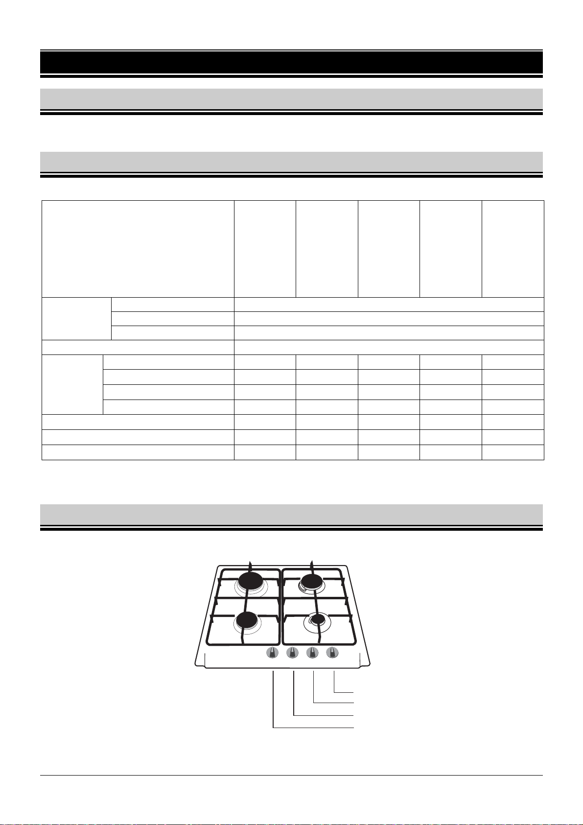
1.3 HOB MODELS
6FI-4GLSX; 6FID-4GLSX; 6FID-4GLX; 6FID-4GLB;
UK
Rapid burner R
3,0 kW
Semi-rapid burner SR
1,75 kW
Semi-rapid burner SR
1,75 kW
Auxiliary burner AUX
1,0 kW
Control knob for SR burner
Control knob for AUX burner
Control knob for SR burner
Control knob for R burner
Fig. 1
3
Page 5
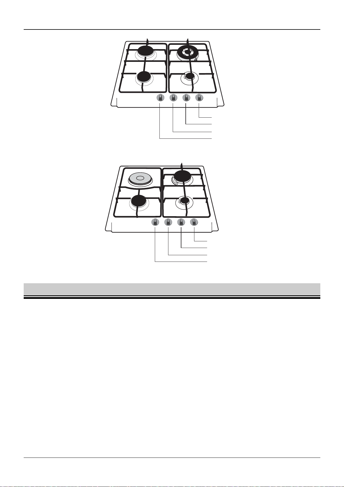
6FI-4GLSTX;
OVERVIEW
Rapid burner R
3,0 kW
Semi-rapid burner SR
1,75 kW
6FID-31MLX;6FID-31MLSX
Electric plate
1,5 kW
Semi-rapid burner SR
1,75 kW
Triple-crown burner TC
3,8 kW
Auxiliary burner AUX
1,0 kW
Control knob for TC burner
Control knob for AUX burner
Control knob for R burner
Control knob for SR burner
Fig. 2
Great burner R
3,0 kW
Auxiliary burner AUX
1,0 kW
Control knob for R burner
Control knob for AUX burner
Control knob for SR burner
Control knob for the electric plate
Fig. 3
1.4 SAFETY GUIDELINES
The gas burners, electric plate HOT PLATE, grates, pots and pans become hot when hob is in use.
Handle with care to avoid burns. Pay special attention to children.
When using the drawer under the hob, do not keep flammable or hot-sensitive objects in it.
All electric cords of domestic appliances near the operating hob should be kept away from the hot
burners and electric plate.
Use protective gloves when removing hot pots and pans from the hob.
Keep flammable objects away from burners.
Do not put deformed or unstable pots and pans on grates as they can overturn and flood burners.
Do not put empty pots and pans on the operating burner or electric plate.
Reduce or turn off the flame before removing pots and pans from burners.
While in use, the hob must not be left unattended. Never leave the operating device unattended
especially when frying as overheated oil or fat may ignite.
When in use, the hob will produce heat and moisture in the room in which it has been installed.
Ensure that the room is properly ventilated. Natural ventilation openings should be opened or a
mechanical ventilation device (cooker hood with extractor) should be installed.
Never use the hob to heat a room.
It is strictly forbidden to modify the hob so that it can use another type of gas or to make changes in
the electrical or gas system of the appliance
4
UK
Page 6
INSTALLATION
In case of a gas leakage:
immediately close the valve of the gas system or gas bottle
ventilate the room thoroughly
call gas service
During this time do not:
light matches or smoke
turn on or turn off electrical devices (radio, door bell, light) or mechanical devices that
spark.
If the gas coming out of a leaky valve of the gas bottle will ignite, put a wet blanket on the
bottle to cool it and then close the valve.
DO NOT USE A DAMAGED GAS BOTTLE!
Never use the hob if its supply wire or plug is broken.
Warning !
Should you find any crack on the electric plate, immediately disconnect the hob
from the electric system and call an authorised service personnel.
1.5 PREPARATION
1. Remove all packaging items, including protective layers, from chromed elements and stainless steel
parts.
2. Wipe enamelled surfaces with a soft, damped cloth.
3. Make sure that all parts of burners are positioned correctly.
4. Before the first use, turn the electric plate ON for approx. 5 minutes by turning the knob to position
"6", exceptionally without any pot or pan. During this time the protective layer on the plate will burn
out. When the plate has cooled down, wipe the plate with a dry cloth.
2 INSTALLATION
2.1 GENERAL NOTES
Attention !
1. This hob must be installed and repaired only by an authorised fitter according to
the manufacturer’s instructions.
2. Before installation, disconnect the hob from the electric supply.
After unpacking, make sure that the hob has no visible damage and the power cord is in good
condition. If there is a damage, please contact our Customer Service.
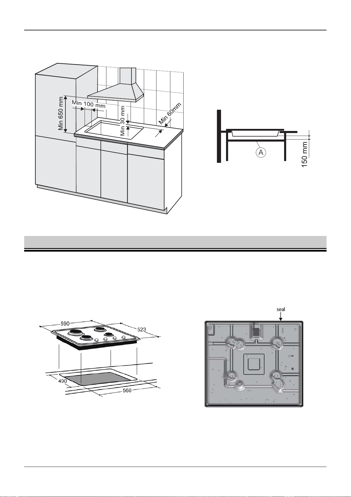
This hob may be installed on a worktop that is at least 30mm thick (Fig. 5). The worktop must be
heat-resistant.
The wall next to the rear side of the hob should be made of incombustible material.
A minimum distance of 100mm must be maintained between the side edges of the hob and any
adjacent furniture.
To reduce negative impact of draught on burner operation, do not install this hob on the window-door
line.
There should be a free space left over the hob for discharging fumes. The best solution is to install a
cooker hood which will absorb and discharge these fumes. The minimum distance between the hob
and cooker hood is 650mm.
UK
5
Page 7
INSTALLATION
There must not be any cabinet fitted right above the hob.
In case of mounting a horizontal partition "A" under the hob, leave the distance at least 150mm
between the hob and the partition (Fig. 6).
Fig. 5 Fig. 6
2.2 GAS HOB INSTALLATION
1. Make the 490 x 560 [mm] rectangular cut-out in the worktop. The dimensions of the cut-out can be
found in Fig. 7.
2. The hob is equipped with a seal with tape-protected adhesive surface. Remove the tape from the
seal.
3. Turn the hob upside down and stick the seal around the internal edge (Fig. 8).
Fig. 7 Fig. 8
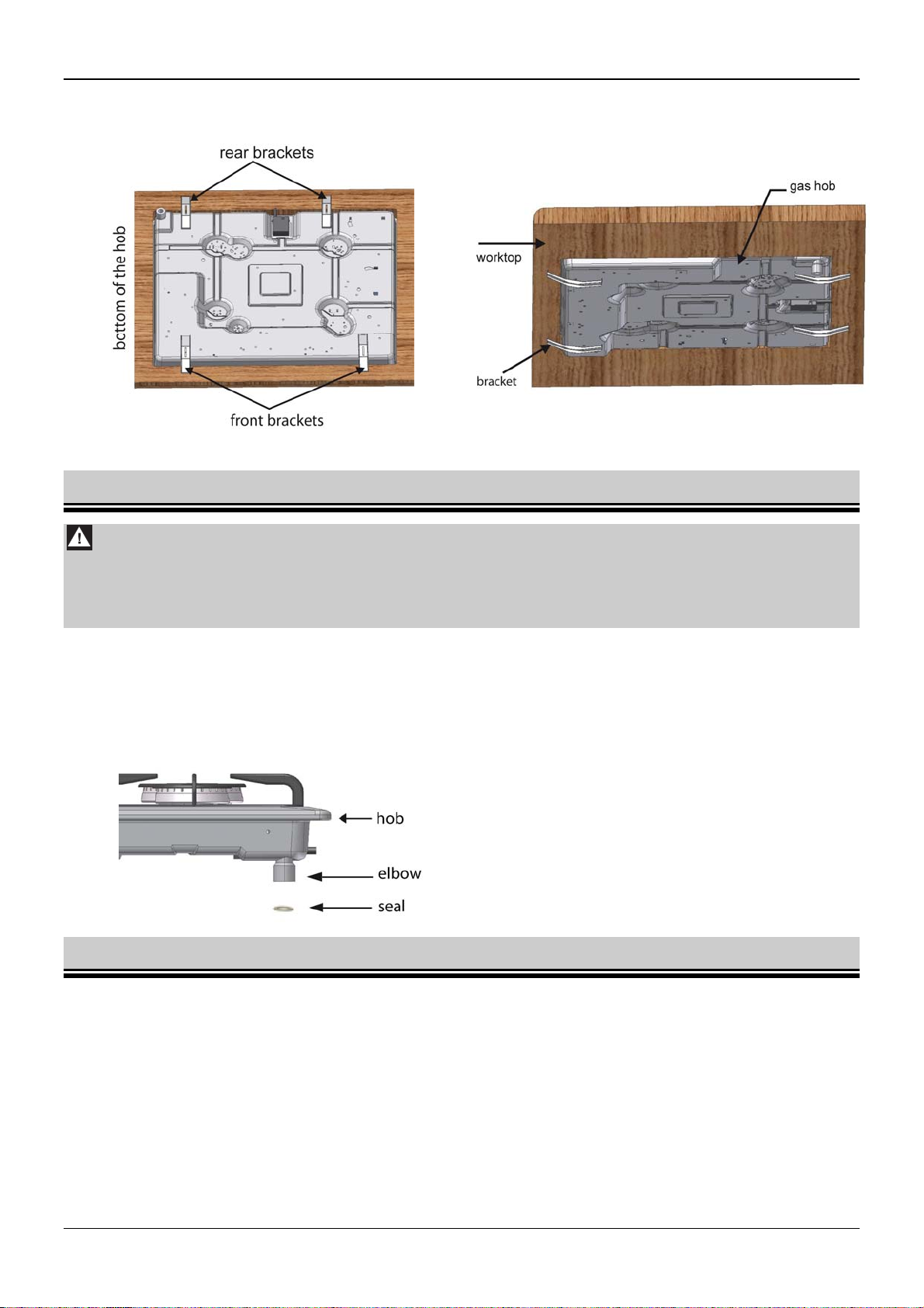
4. Place the hob in the middle of the cut-out and push it so that the seal adheres tight to the worktop.
5. Fix the hob with the four brackets which are included together with other connecting parts (Fig. 9 and
10).
6
UK
Page 8
INSTALLATION
6. After installing the hob, the horizontal partition "A" may be placed under the worktop which will
protect the user against accidental touching of a hot hob from the bottom.
Fig. 9 Fig. 10
2.3 CONNECTING THE HOB TO THE NATURAL GAS SUPPLY
Attention !
1. The hob must be connected to the gas system according to relevant regulations
and by an authorised gas fitter.
2. Before installation, make sure that the shut-off cock is closed.
This hob is designed for gas and pressure indicated on the rating plate. The hob is equipped with an
elbow and seal (Fig. 11).
Connection to the internal gas system should be either rigid or with a flexible metal pipe.
Gas supply is ended with a shut-off cock. The shut-off cock should be easily accessible after
installing the hob in the worktop.
Fig. 11
2.4 CONNECTING THE HOB TO THE LIQUID GAS BOTTLE
The hob may be converted for use with liquid gas. For this purpose nozzles in burners have to be
replaced and knobs have to be adjusted.
If this hob is intended for use with gas bottles, it should not be installed in a cellar or any other
compartment with a floor below ground level as the liquid gas is heavier than air and accumulates at
the floor level.
When connecting the hob to the gas bottle, use a certified rubber hose.
Each time the gas bottle is connected, check the tightness of the valve on the gas bottle and the
connection and operation of the reducer.
UK
7
Page 9
ATTENTION !
1. Checking the leakage with an open flame (e.g. with a match or a candle) is
unacceptable. It may lead to an explosion !
2. Check condition of the hose and connection tightness regularly, accord ing to the
valid regulations.
2.5 NOZZLE REPLACEMENT
ATTENTION !
Before nozzle replacement and adjustments, disconnect the hob from the mains.
Nozzle diameters for particular gas type are shown in Table 2.
Table 2
AUX burner SR burner R burner TC burner
INSTALLATION
G 20 20 mbar
X072 Z097 Y118 K1,35
G 30/31 29/37 mbar
050 065 085 098
The hob is adjusted to the type of gas and pressure stated on the appliance's rating plate.
In the event of a change of the type of gas replace the nozzles and adjust the taps.
Before beginning these activities you must:
– shut down the cock shutting off the gas supply system or cylinder from the hob,-shut
down all the taps in the hob,
–
disconnect the hob from the mains.
Then:
– remove the burners' lids and rings,
–
remove the nozzles with socket wrench no. 7 and replace them with new ones in
accordance with table2,
–
put burners' rings and lids back,-
adjust the taps and check the connections for soundness
Fig. 12
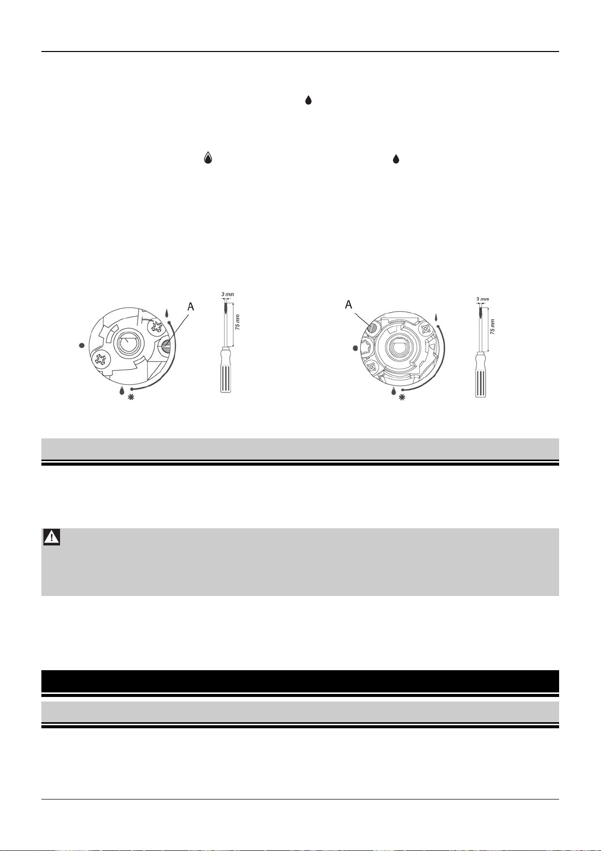
2.6 ADJUSTING CONTROL KNOBS
ADJUSTING THE TAPS
The adjustment of a gas tap consists in setting the burner flame in the simmering position. To
adjust the taps remove all the knobs and control panel.
8
UK
Page 10
OPERATION
Then:
– open the gas flow with a knob and light the adjusted burner,
– set the knob in the simmering position . and then, without changing that position,
remove it from the tap's mandrel
turn the adjusting screw "A" (Fig. 13) and observe the flame; set such a height of a flame
so as it will not be extinguished by a small draught and while quickly turning the knob
from full flame position to the economical flame position and vice versa
a knob is properly adjusted when the flame cone is green-blue and its height is about 2-
4mm;
if there are significant pressure changes in the gas supply system (flame height changes
in a full flow setting), the economical flame should be set with the low gas pressure in
such a way that it will not be extinguished during normal operation
after adjustment, put on the knob and turn off the flame.
Knob without protection Knob with protection
Fig.13
2.7 CONNECTING THE HOB TO THE MAINS
The hob is equipped with a cord without a plug. Before connecting the hob to the mains make sure that:
mains voltage complies with data found on the rating plate,
power of the electric system is sufficient when compared with the power consumption of the
hob.
Attention !
1. The plug should be installed by a qualified authorised fitter.
2. The hob socket must be easily accessible for the user.
3. Ensure that the supply cord does not come into contact with hot parts of the hob.
The hob should be connected to the socket with a properly connected protecting terminal. Connecting
the hob to the socket without a protecting contact creates a risk of electric shock in case of a failure of
the electric system.
If the supply cord is damaged, it must be replaced. Contact the manufacturer, a service workshop or a
qualified person to avoid danger.
3 OPERATION
3.1 GAS BURNERS
Never take off the grates or place pots and pans directly on burners.
Prevent pots and pans boiling over and flooding burners.
Before opening a gas system or gas bottle valve make sure that all control knobs are closed.
UK
9
Page 11
OPERATION
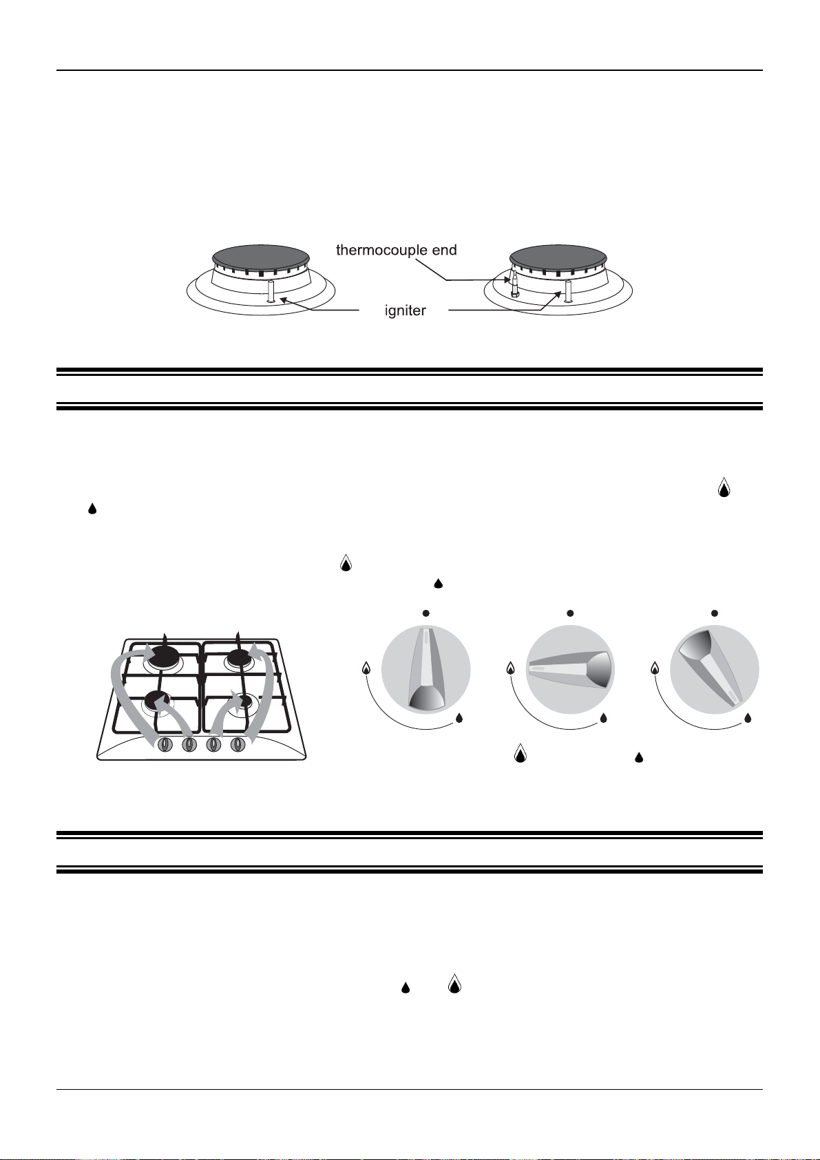
For the proper operation ensure that burners and igniters are clean and dry.
If the hob is equipped with a flame failure protection after igniting the burner keep the control
knob fully pushed for a while to activate the protection.
Do not overload the grates.
Never touch hot burners, graters, pots and pans.
To obtain proper and economical burners operation make sure that:
flame height is adequate,
pots and pans are properly selected.
Burner without
flame failure
protection
Burner with
flame failure
protection
Fig. 14
3.1.1 FLAME ADJUSTING
Gas flow in individual burners is opened and closed using control knobs.
Before igniting the burner make sure that the corresponding control knob is to be operated.
Corresponding burners and control knobs are shown in Fig. 15.
Flame height depends on the control knob position (Fig. 16). Adjust the flame only between and
.
Flame should not spread beyond the bottom of the vessel but spread on 2/3 of the vessel’s bottom.
This will ensure gas efficiency and the flame will not singe pots and pans.
When the control knob is in position the flame is high. High flame should be used until a liquid
starts boiling and then turn down the flame to small
(economical) for further cooking.
0 – burner turned off;
– high flame; – small flame
(economical)
Fig. 15 Fig. 16
3.1.2 IGNITING BURNERS
Hobs: 6FID-31MLX; 6FID-4GLX; 6FID-4GLB
push the knob of a burner until it stops, then turn it anticlockwise and push down until the burner
ignites
after ignition release the knob
adjust to the desired flame height between
Hobs: 6FI-4GLSX; 6FID-4GLSX; 6FI-4GLSTX;6FID-31MLSX
push the knob of a burner until it stops, then turn it anticlockwise and push down until the burner
ignites, do not release the knob for another 5 seconds in order to activate flame failure
protection
and
10
UK
Page 12
OPERATION
if the flame goes out, repeat these steps keeping the knob pushed for 5 seconds longer
adjust to the desired flame height between
and
3.1.3 TURNING OFF BURNERS
Turn the control knob clockwise to the zero position marked "".
3.1.4 OPERATING THE HOB SUPPLIED WITH LIQUID GAS FROM BOTTLE
Before igniting the first burner, open the gas bottle valve and then ignite burners as described above.
When closing gas supply before turning off the last burner:
close the gas bottle valve
after the flame is extinguished close the relevant control knob
The gas bottle valve should be closed when the hob is not used.
3.1.5 VESSEL SELECTION
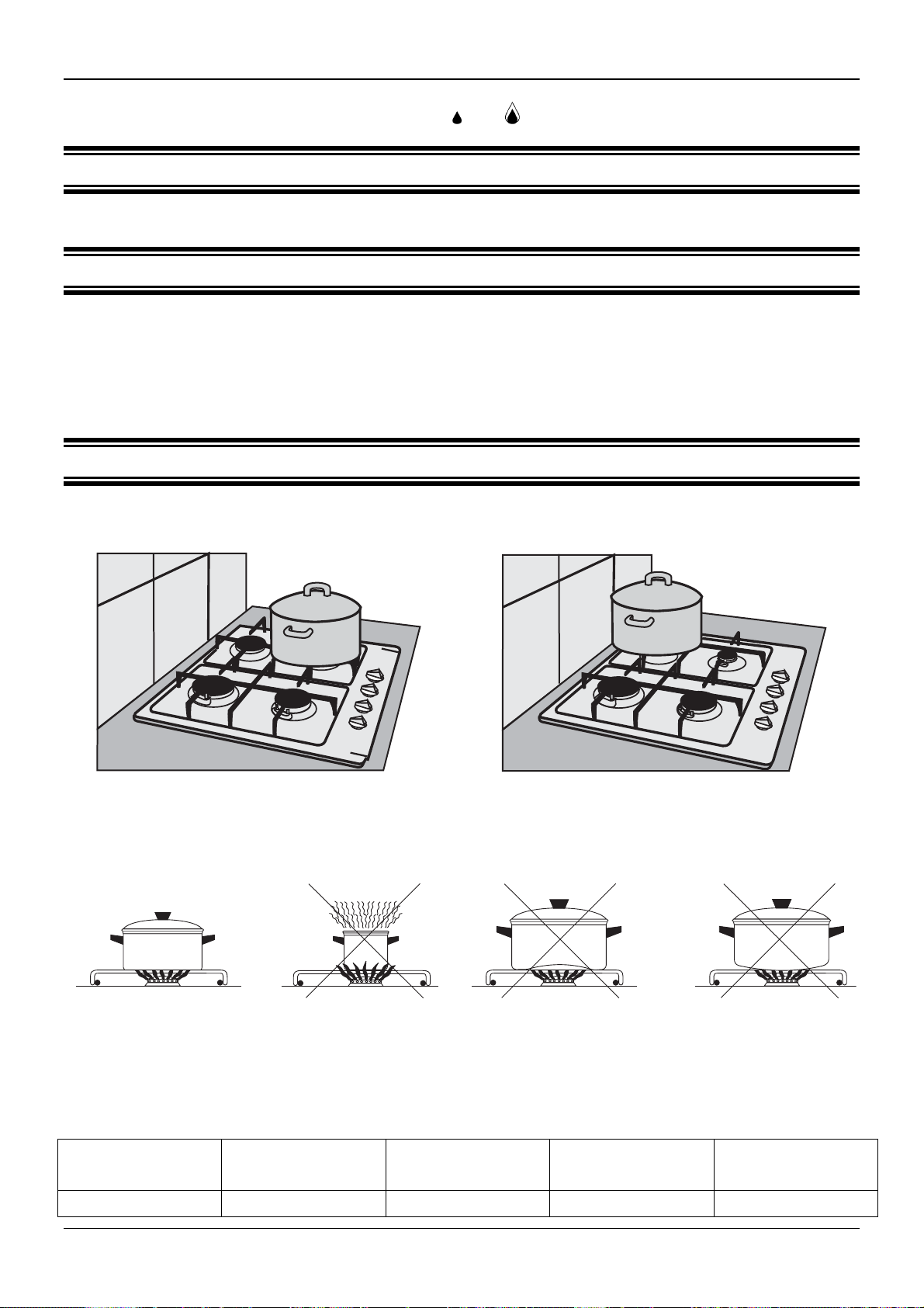
Pots should not be too high. It is recommended to use vessels whose height is about 2/3 of their
bottom diameter.
Fig. 17 Fig. 18
Do not place large pots in the front part of the
hob as the burner flame may overheat knobs.
Do not place large pots in the rear part of the
hob as the flame may overheat the wall.
Adequate vessel
Recommended vessels diameters for particular burners:
Triple-crown
Burner TC
23 – 30 cm 18 – 28 cm 16 – 26 cm 14 – 22 cm 12 – 16 cm
Vessel too small in
relation to burner
size
Great
Burner GR
Fig. 19
Rapid
Burner R
Concave bottom Convex bottom
Semi-rapid
Burner SR
Auxiliary
Burner AUX
UK
11
Page 13
OPERATION
3.2 OPERATING THE HOT PLATE
3.2.1 OPERATING HINTS
Keep the plate clean. Dirty plate does not transfer all power.
Except first use, turn on the plate only after putting a pot on it.
Never put wet vessels on the plate as moisture causes corrosion.
Never sprinkle a hot plate with cold water.
Switch the plate off a few minutes before finishing the cooking as the plate accumulates heat and
remains hot for some time after switching it off.
Do not use the plate to prepare food wrapped in aluminium foil or in plastic containers. Do not put
plastic plates or other objects on the plate.
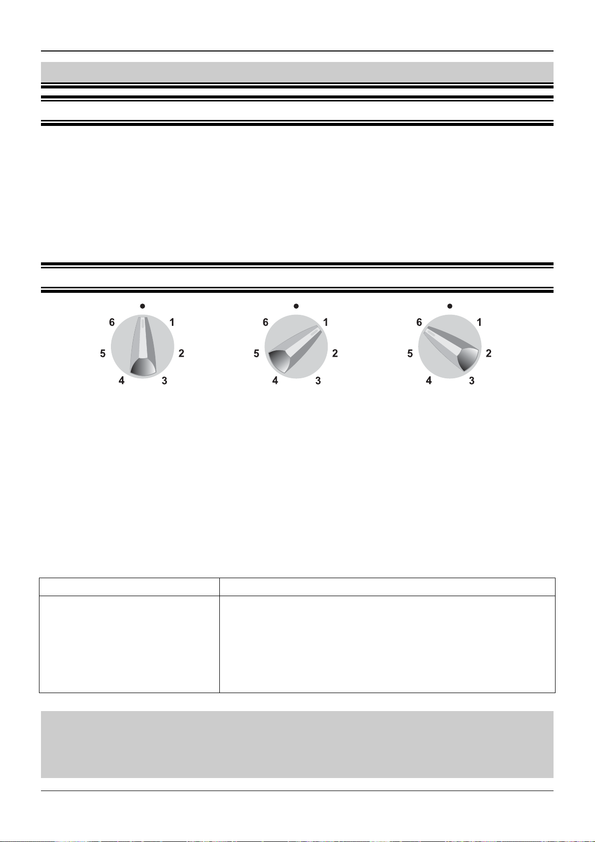
3.2.2 CONTROL KNOB OF THE ELECTRIC PLATE
Heating power is adjusted using the 7-position control knob. Power changes in steps. Such controls
ensure proper and economical adjustment of the plate heating power.
A control knob may be turned in both directions. Digits 1 to 6 indicate control knob positions (Fig.
20). These positions correspond to certain heating power.
Plate turned off Minimum heating power Maximum heating power
Fig. 20
Using the 7-positon control knob
Knob setting Suitable for
6
5
4
3
2
1
0
rapid cooking or intensive frying
intensive roasting of meat, fish
mild roasting
further cooking huge volumes of dish, thick soups
cooking potatoes, soups
simmering vegetables, fish in its own juice
plate turned off
Important !
1. Except the first use, do not turn on the hot plate before putting a pot on it.
2. Put a thin layer of protective agent on the plate, if it will not be used for a longer
time.
12
UK
Page 14
OPERATION
Cooking Roasting
Turn the knob to position 6 and wait till the
liquid starts boiling and turn to position 2 for
further cooking. Adjust heating power
accordingly.
Turn the knob to position 6 and heat the oil.
Then put ingredients into vessel and turn the
knob to position 4. Adjust heating power
accordingly.
ATTENTION !
After switching off the plate remains hot for some time. Do not touch the plate or
place any vessels or objects on it. Pay special attention to children.
It is recommended to switch the electric plate off for 5 to 10 minutes before finishing boiling to make
full use of its final power.
Do not put unused vessels on the electrical plate.
3.2.3 VESSEL SELECTION
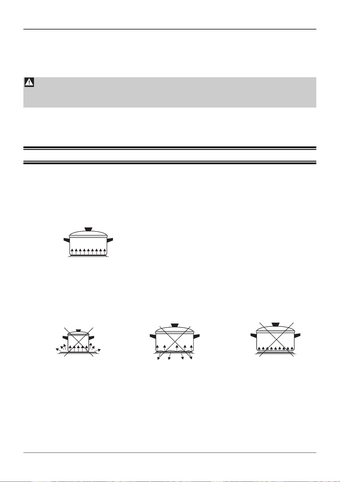
Pots and pans put on the electrical plate should have thick flat and dry bottoms with a diameter equal
or slightly larger than the plate diameter. Large amount of heat is wasted if the vessel bottom has a
smaller diameter.
Uneven bottoms extend boiling time and raise power consumption.
Vessel should be covered to prevent accumulating too much fumes in the kitchen.
Correct !
Fig. 21
Low power consumption
Good heat conducting
even bottom of the vessel
bottom diameter is the same as plate diameter
cover tightly adheres to the vessel
Incorrect !
High power consumption
Poor heat conducting
Long cooking time
Vessel too small Uneven vessel bottom Dirty plate surface
Fig. 22
UK
13
Page 15
CLEANING AND MAINTENANCE
4 CLEANING AND MAINTENANCE
Attention !
Before cleaning, you must disconnect the hob’s plug from the socket and turn off all
burners.
4.1 GENERAL RECOMMENDATIONS
Appliance must be regularly cleaned in order to maintain proper technical condition and good
appearance.
Never clean the hob with coarse agents which scratch surfaces, sharp tools, wire sponges or
aggressive chemical agents.
Clean the control panel and knobs with mild cleaning fluids without abrasives to prevent damaging
overprints.
For the proper hob operation, ensure that burner elements and igniters are clean and dry.
Soak dirty grates in warm water with detergent, then wash and dry the grates.
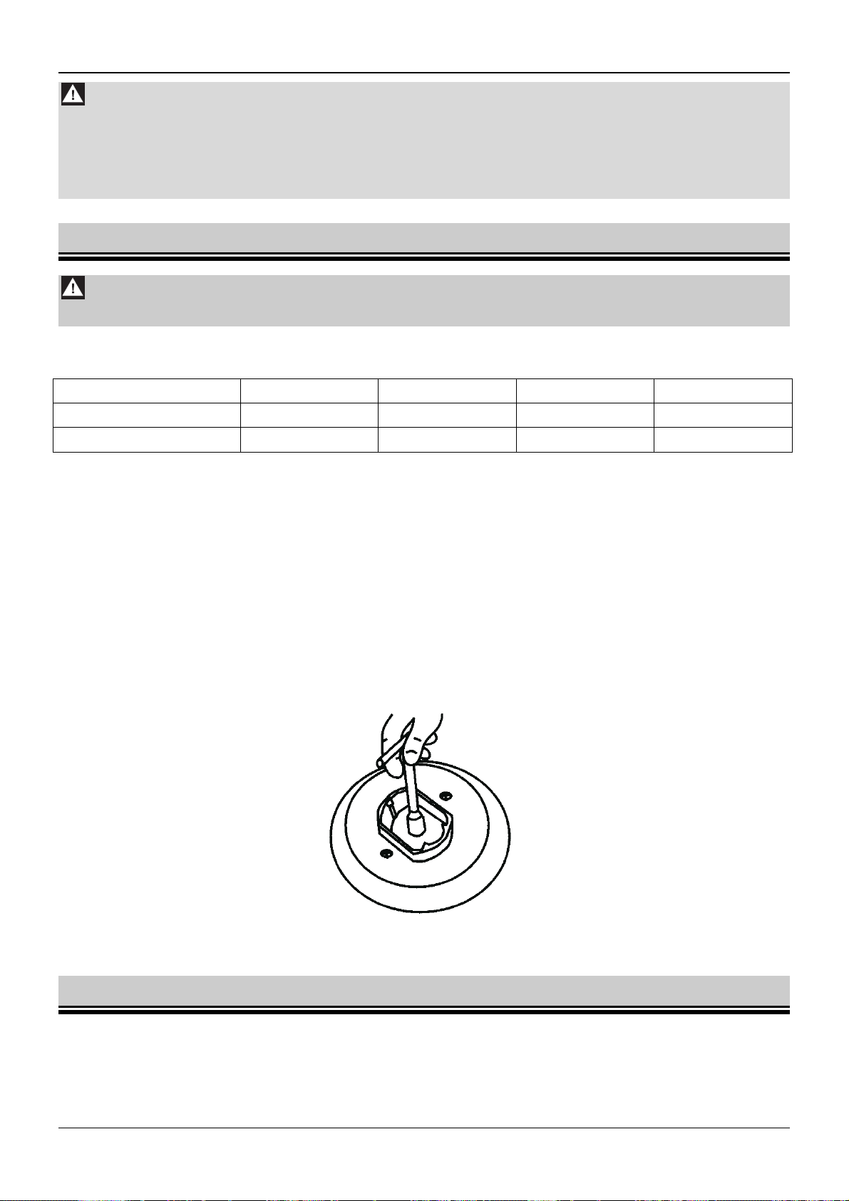
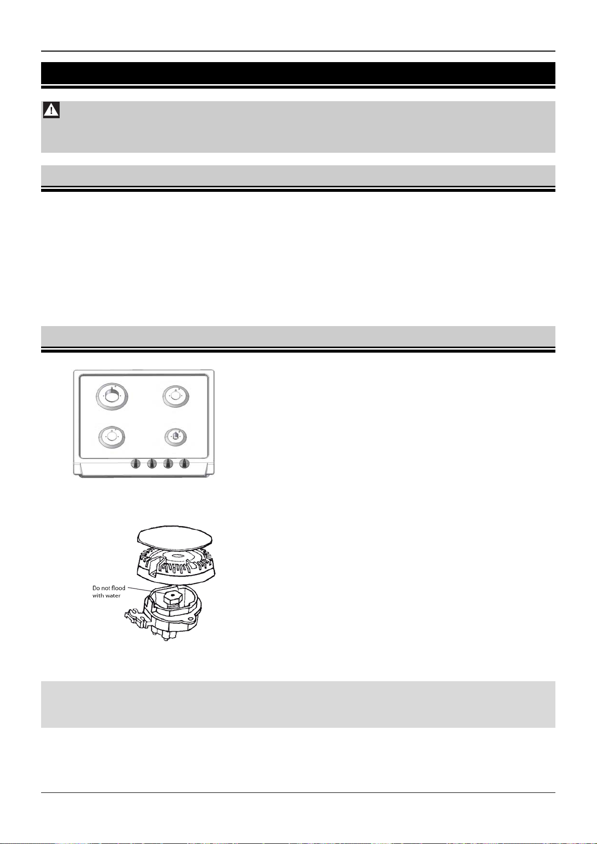
4.2 CLEANING THE HOB AND BURNERS
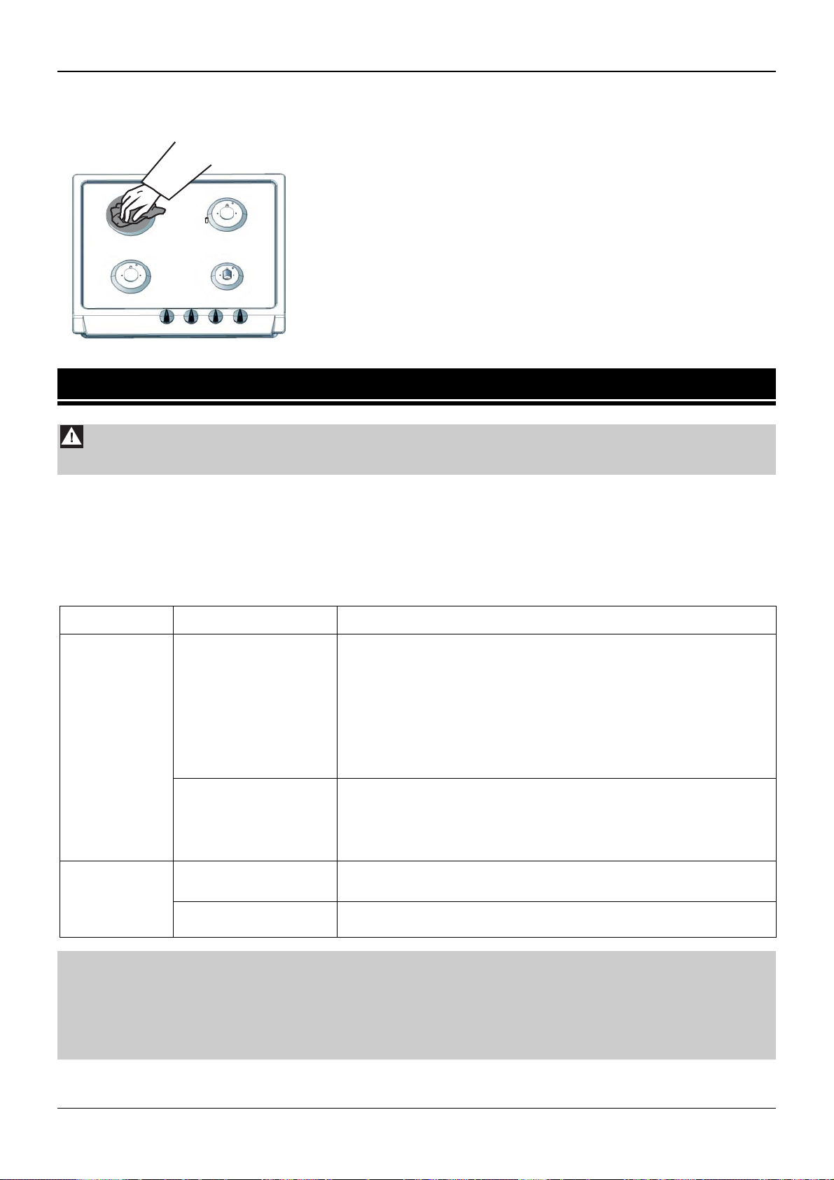
Before cleaning the hob remove the grates and burner
caps and crowns.
Wipe the enamelled surface of the hot plate using a soft
cloth or sponge moistened with a solution of hot water
and mild detergent.
The hob surface around burners should be always kept
clean. It is very important because during normal hob
operation contaminations accumulating in the gap
Fig. 23
between burner crown and the hob impair the gas
mixture burning.
During cleaning the hob, avoid excess water to prevent
it from getting into the hob recess and flooding the
nozzles (Fig. 24). If the nozzle is flooded, the burner will
not ignite.
The nozzle should always be clean. A dirty nozzle may
clog and the flame will be low or the burner will not ignite
at all. Clean the nozzle with a brush moistened with
solvent.
Fig. 24
ATTENTION !
Burners, igniters and thermocouple ends should be cleaned after each flooding.
Blooms and contaminations must be removed regularly.
To clean the burner, remove its cap and crown (Fig. 12), soak them in warm water with detergent
and wash each part separately.
Use a sponge or a brush to wash burner parts and a steel wire to unblock flame openings. After
cleaning, make sure that the flame openings are not clogged.
14
UK
Page 16
ABNORMAL HOB OPERATION
Cleaned burner parts should be thoroughly dried because if they are wet the gas will not burn or will
burn improperly. After drying, re-install the burner elements in the order reverse to that used during
their removal and do not damage igniters and thermocouple ends.Cleaning the electric plate
Clean the plate with a soft cloth or a sponge. Nickel
plated finishing rings should be washed with mild
cleaning agents. After cleaning preserve the plate
with white mineral or silicone oil. Do not use
vegetable or animal oils for preserving the plate.
Fig. 25
5 ABNORMAL HOB OPERATION
Attention !
Before troubleshooting disconnect the hob plug from the electric socket.
Failures can occur during the hob operation. Some minor faults may be remedied by the user
according to directions in Table 3.
During the warranty period, all repairs except those specified below should be carried out by an
authorised service workshop.
After the warranty period, a user should have the appliance inspected by a service shop regularly.
Table 3
Symptoms
Burner will not
ignite
The igniter
will not ignite
gas (no
spark)
Attention !
1. If after following the steps above the hob does not operate normally, contact the
nearest authorised service workshop. Never use a faulty hob before it is repaired.
2. If the hob is not going to be used for a longer period of time, clean it thorou ghly,
close the shut-off valve and unplug the hob from mains.
Causes Troubleshooting
Close all control knobs
Close shut-off cock
Clogged flame
openings in the
burner.
Ventilate the room
Remove and clean burner parts making sure that flame
openings are not clogged
Install all burner parts properly and try to ignite the burner
again
Remove all burner parts
Clogged (flooded)
nozzle
Clean and dry the hob recess of the relevant nozzle
Clean the nozzle and unblock it with thin copper wire if
necessary (never use the steel wire or enlarge the opening)
Open circuit in
electric system
Contaminated
burners or igniters
Check the fuse in a house electric system and replace if
burnt out
Clean and thoroughly dry burners and igniters
UK
15
Page 17

ATTENTION !
1. Lisez entièrement ce manuel d'instructions avant d'installer ou d'utiliser la table de cuisson.
2. Cette table de cuisson doit être installée conformément aux réglementations en vigueur et
utilisée uniquement dans des pièces correctement ventilées.
3. Avant d'installer cet appareil, assurez-vous que les conditions locales en termes
d'alimentation en gaz (type de gaz et pression) correspondent aux paramètres de la table de
cuisson. Les paramètres de la table de cuisson se trouvent sur la plaque signalétique.
4. Cette table de cuisson doit être connectée au réseau de gaz interne ou à une bouteille de gaz
liquide et doit être réglée par un monteur d'installations au gaz ou un dépanneur agréé, le
certificat de garantie faisant preuve. Le cas contraire entraînerait l'annulation de la garantie.
5. Le fabricant ne saurait être tenu pour responsable d'aucun dommage corporel ou matériel
dus à une installation ou une utilisation incorrectes de cette table de cuisson.
6. Cette table de cuisson ne doit être réparée que par un personnel de maintenance agréé. Des
réparations effectuées de manière incorrecte peuvent entraîner des risques importants.
N'utilisez jamais une table de cuisson endommagée avant qu'elle ne soit réparée.
7. N'effectuez jamais les réparations par vous-même, sans quoi la garantie serait définitivement
annulée.
8. Cette table de cuisson est un appareil de classe de sécurité I ; elle doit être connectée au
système électrique à l'aide d'un circuit de protection externe opérationnel.
9. Avant de procéder à l'installation, laissez cet appareil reposer pendant 8 heures dans la pièce
où il sera installé.
10. Cette table de cuisson n'est connectée à aucune conduite d'évacuation. Cette table de
cuisson doit être installée et connectée conformément aux réglementations en vigueur. Une
attention toute particulière doit être portée aux conditions de ventilation. Assurez-vous de
l'ouverture permanente de grilles d'aération ou de la présence d'un système de ventilation
(hotte d'aspiration).
11. Lorsque vous utilisez cette table de cuisson pendant une durée prolongée, une ventilation
supplémentaire peut s'avérer nécessaire. Vous pouvez à cette fin ouvrir une fenêtre ou
accroître la vitesse de l'extracteur (le cas échéant).
12. Conservez les éléments d'emballage hors de portée des enfants afin de ne pas les exposer au
moindre danger.
13. Le fabricant se réserve le droit d'apporter des modifications à ce produit afin d'en améliorer la
qualité ou de le moderniser, sans préavis. Ces modifications n'altéreront pas le
fonctionnement de cette table de cuisson.
Ces appareils sont conformes aux directives CEE suivantes :
73/23/CEE – Directive Basse tension
89/336/CEE – Directive Compatibilité électromagnétique
90/396/CEE – Directive relative aux appareils à gaz
1
FR
Page 18

SOMMAIRE
1
PRESENTATION ....................................................................................................... 3
1.1 CHAMP D'APPLICATION DE LA TABLE DE CUISSON............................................................................3
1.2 DONNEES TECHNIQUES..........................................................................................................................3
1.3 MODELES DE TABLES DE CUISSON ......................................................................................................3
1.4 DIRECTIVES DE SECURITE......................................................................................................................4
1.5 PREPARATION...........................................................................................................................................5
2 INSTALLATION......................................................................................................... 5
2.1 REMARQUES D'ORDRE GENERAL..........................................................................................................5
2.2 INSTALLATION DE LA TABLE DE CUISSON AU GAZ.............................................................................6
2.3 RACCORDEMENT DE LA TABLE DE CUISSON AU GAZ NATUREL......................................................7
2.4 RACCORDEMENT DE LA TABLE DE CUISSON A UNE BONBONNE DE GAZ LIQUIDE ......................8
2.5 REMPLACEMENT DES BUSES.................................................................................................................8
2.6 REGLAGE DES BOUTONS DE COMMANDE...........................................................................................9
2.7 RACCORDEMENT DE LA TABLE DE CUISSON AU RESEAU ELECTRIQUE........................................9
3 UTILISATION.......................................................................................................... 10
3.1 BRULEURS A GAZ...................................................................................................................................10
3.1.1 Réglage de la flamme...........................................................................................................................10
3.1.2 Allumage des brûleurs ..........................................................................................................................11
3.1.3 Extinction des brûleurs..........................................................................................................................11
3.1.4 Utilisation de la table de cuisson alimentée par une bonbonne de gaz liquide....................................11
3.1.5 Sélection des récipients........................................................................................................................12
3.2 UTILISATION DE LA PLAQUE CHAUFFANTE........................................................................................12
3.2.1 Conseils d'utilisation..............................................................................................................................12
3.2.2 Bouton de commande de la plaque électrique .....................................................................................13
3.2.3 Sélection des récipients........................................................................................................................14
4 NETTOYAGE ET ENTRETIEN ................................................................................. 14
4.1 RECOMMANDATIONS D'ORDRE GENERAL .........................................................................................14
4.2 NETTOYAGE DE LA TABLE DE CUISSON ET DES BRULEURS..........................................................15
4.3 NETTOYAGE DE LA PLAQUE ELECTRIQUE.........................................................................................16
5 FONCTIONNEMENT ANORMAL DE LA TABLE DE CUISSON ................................. 16
FR
2
Page 19

PRESENTATION
1 PRESENTATION
1.1 CHAMP D'APPLICATION DE LA TABLE DE CUISSON
Cette table de cuisson au gaz et à l'électricité est destinée à un usage domestique uniquement. Elle ne
doit être utilisée à aucune autre fin.
1.2 DONNEES TECHNIQUES
Tableau 1
6FI-4GLSX
6FID-4GLSX
6FID-31MLSX
6FID-31MLX
6FI-4GLSTX
6FID-4GLX
6FID-4GLB
Hauteur totale 90
Dimensions
générales
Largeur 590
[mm]
Profondeur 523
Tension d'alimentation 230 V ~ 50 Hz
Brûleur AUX 1,0 kW
Brûleurs à
gaz
Brûleur SR 1,75 kW
Brûleur R 3,0 kW
Brûleur TC 3,8 kW
Plaque chauffante électrique 145 mm / 1,5kW
Allumeurs des brûleurs
Dispositif de protection de flamme
Les couleurs des TABLES DE CUISSONS varient. Les lettres suivantes symbolisent les différentes couleurs :
X – inox ; B – blanc ; A – anthracite.
1.3 MODELES DE TABLES DE CUISSON
6FI-4GLSX ; 5FID-4GLSX ; 6FID-4GLX ; 6FID-4GLB
Brűleur rapide R
3,0 kW
Brűleur semi-rapide SR
1,75 kW
Brűleur semi-rapide SR
1,75 kW
Brűleur auxiliaire AUX
1,0 kW
Bouton de commande du brűleur SR
Bouton de commande du brűleur AUX
Bouton de commande du brűleur SR
Bouton de commande du brűleur R
3
FR
Page 20

6FI-4GLSTX
PRESENTATION
Fig. 1
Brűleur rapide R
3,0 kW
Brűleur semi-rapide SR
1,75 kW
6FID-31MLX ;6FID-31MLSX
Plaque électrique
1,5 kW
Brűleur semi-rapide SR
1,75 kW
Brűleur triple couronne TC
3,8 kW
Brűleur auxiliaire AUX
1,0 kW
Bouton de commande du brűleur TC
Bouton de commande du brűleur AUX
Bouton de commande du brűleur SR
Bouton de commande du brűleur R
Fig. 2
Brűleur rapide R
3,0 kW
Brűleur auxiliaire AUX
1,0 kW
Bouton de commande du brűleur R
Bouton de commande du brűleur AUX
Bouton de commande du brűleur SR
Bouton de commande de la plaque
électrique
Fig. 3
1.4 DIRECTIVES DE SECURITE
Les brûleurs à gaz, la plaque chauffante électrique, les grilles, les casseroles et les poêles
deviennent chauds lorsque la table de cuisson est en cours d'utilisation. Manipulez ces éléments
avec précaution pour éviter tout risque de brûlure. Soyez particulièrement vigilant avec les enfants.
Lorsque vous utilisez un tiroir sous la table de cuisson, n'y rangez aucun objet inflammable ou
sensible à la chaleur.
Lorsque vous utilisez la table de cuisson, tous les cordons électriques de vos appareils ménagers à
proximité doivent être éloignés des brûleurs et de la plaque électrique.
Utilisez des gants de protection lorsque vous retirez les casseroles et les poêles de la table de
cuisson.
Maintenez les objets inflammables hors de portée des brûleurs.
Ne posez pas de casseroles ou de poêles déformées sur les grilles ; elles risqueraient de se
renverser et de noyer les brûleurs.
Ne posez pas de casseroles ou de poêles vides sur les brûleurs ou sur la plaque électrique lorsque
ces derniers sont actifs.
Réduisez ou éteignez la flamme avant de retirer les casseroles ou les poêles des brûleurs.
Lorsqu'elle est active, la table de cuisson ne doit pas rester sans surveillance. Ne laissez jamais
l'appareil actif sans surveillance, tout particulièrement lors des fritures car l'huile ou les matières
grasses surchauffées risquent de s'enflammer.
FR
4
Page 21

UTILISATION
Lorsqu'elle est active, la table de cuisson produit de la chaleur et de l'humidité dans la pièce où elle
est installée. Assurez-vous que cette pièce est correctement ventilée. Des trous d'aération naturels
doivent être ouverts ; autrement, un mécanisme de ventilation (hotte d'aspiration avec extracteur)
doit être installé.
N'utilisez jamais la table de cuisson dans le but de chauffer une pièce.
Il est strictement interdit de modifier la table de cuisson pour qu'elle puisse utiliser un autre type de
gaz ou d'apporter des modifications au système à gaz ou électrique de l'appareil.
En cas de fuite de gaz :
Fermez immédiatement le robinet du système à gaz ou de la bonbonne de gaz
Aérez largement la pièce
Appelez un monteur d'installations au gaz
Pendant ce temps :
N'allumez ni allumettes, ni cigarettes
N'allumez et n'éteignez aucun appareil électrique (radio, sonnette de porte, lumière) et
aucun appareil mécanique pouvant produire des étincelles.
Si le gaz qui fuit par un robinet défectueux de la bonbonne de gaz s'enflamme, placez une
couverture humide sur la bonbonne pour la refroidir, puis fermez le robinet incriminé.
N'UTILISEZ JAMAIS DE BONBONNE DE GAZ ENDOMMAGEE !
N'utilisez jamais la table de cuisson lorsque sa prise ou son cordon électrique est
endommagé.
Avertissement !
Si la plaque électrique présente la moindre fêlure, débranchez immédiatement la
table de cuisson du système électrique et faites appel à un personnel de
maintenance agréé.
1.5 PREPARATION
1. Retirez tous les matériaux d'emballage des éléments chromés et des pièces en acier inoxydable,
notamment les revêtements de protection.
2. Essuyez les surfaces émaillées à l'aide d'un linge humide non abrasif.
3. Assurez-vous que toutes les parties des brûleurs sont correctement mises en place.
4. Avant la première utilisation, allumez la plaque électrique pendant environ 5 minutes en tournant le
bouton de contrôle correspondant sur la position 6 ; exceptionnellement, n'y posez aucune casserole
ni aucune poêle. Au cours de cette période, le revêtement de protection sur la plaque va se
consumer. Une fois que la plaque est refroidie, essuyez-la à l'aide d'un linge sec.
2 INSTALLATION
2.1 REMARQUES D'ORDRE GENERAL
Attention !
1. L'installation et les réparations de cette table de cuisson doivent être confiées
uniquement à un monteur agréé, en conformité avec les instructions du fabricant.
2. Avant l'installation, débranchez la table de cuisson de l'alimentation électrique.
Après avoir déballé la table de cuisson, assurez-vous qu'elle ne présente aucun dommage visible et
que le cordon d'alimentation est en bon état. En cas de dommage, contactez notre Service clientèle.
Cette table de cuisson peut être installée sur un plan de travail d'une épaisseur d'au moins 30 mm
(Fig. 5). Ce plan de travail doit être résistant à la chaleur.
5
FR
Page 22

UTILISATION
Le mur à proximité du côté arrière de la table de cuisson doit être construit dans un matériau non
combustible.
Une distance de 100 mm au minimum doit être maintenue entre les bords des côtés de la table de
cuisson et tout meuble adjacent.
Pour réduire l'effet négatif des courants d'air sur le fonctionnement des brûleurs, n'installez pas cette
table de cuisson sur la trajectoire porte-fenêtre.
Laissez un espace libre à gauche de la table de cuisson pour l'évacuation des émanations. La
meilleure solution consiste à installer une hotte d'aspiration afin d'absorber et évacuer ces
émanations. La distance minimale à respecter entre la table de cuisson et la hotte d'aspiration est de
650 mm.
Aucun meuble ou placard ne doit se trouver juste au-dessus de la table de cuisson.
Si vous montez une cloison horizontale « A » sous la table de cuisson, laissez une distance d'au
moins 150 mm entre la table de cuisson et cette cloison (Fig. 6).
Fig. 5 Fig. 6
2.2 INSTALLATION DE LA TABLE DE CUISSON AU GAZ
1. Procédez à la découpe rectangulaire de 490 x 560 [mm] dans le plan de travail. Les dimensions de
la découpe sont indiquées dans la Fig. 7.
2. La table de cuisson est équipée d'un joint adhésif recouvert d'un ruban de protection. Retirez le
ruban du joint.
3. Retournez la table de cuisson à l'envers et collez le joint en suivant le bord interne (Fig. 8).
Fig. 7 Fig. 8
FR
6
Page 23

UTILISATION
4. Placez la table de cuisson au milieu de la découpe et exercez une pression de sorte à faire adhérer
le joint adhésif sur le plan de travail.
5. Fixez la table de cuisson à l'aide des quatre supports inclus avec les autres pièces de montage
(Fig. 9 et 10).
6. Après avoir installé la table de cuisson, vous pouvez mettre en place la cloison horizontale « A »
sous le plan de travail, ce qui permettra d'éviter à l'utilisateur de se brûler en touchant la partie
inférieure de la table de cuisson lorsque cette dernière est chaude.
Fig. 9
Fig. 10
2.3 RACCORDEMENT DE LA TABLE DE CUISSON AU GAZ
NATUREL
Attention !
1. La table de cuisson doit être raccordée au système de gaz par un monteur
d'installations au gaz agréé, en conformité avec les réglementations en vigueur.
2. Avant de procéder à l'installation, assurez-vous que le robinet de fermeture est
fermé.
Cette table de cuisson est conçue pour fonctionner avec le type de gaz et la pression indiqués sur la
plaque signalétique. Cette table de cuisson est équipée d'un coude et d'une rondelle de protection
(Fig. 11).
Le raccordement au système de gaz interne doit être rigide ou effectué à l'aide d'un tuyau métallique
flexible.
Le raccordement au gaz se termine par un robinet de fermeture. Ce robinet de fermeture doit être
aisément accessible une fois la table de cuisson installée dans le plan de travail.
Fig. 11
7
FR
Page 24

UTILISATION
2.4 RACCORDEMENT DE LA TABLE DE CUISSON A UNE
BONBONNE DE GAZ LIQUIDE
Cette table de cuisson doit être adaptée pour une utilisation avec du gaz liquide. A cette fin, les
buses des brûleurs doivent être remplacées et les boutons de commande doivent être réglés.
Si cette table de cuisson est destinée à être utilisée avec des bonbonnes de gaz, elle ne doit pas
être installée dans une cave ou tout autre compartiment dont le plancher se trouve au-dessous du
niveau du sol ; en effet, le gaz liquide étant plus lourd que l'air, il risquerait de s'accumuler au niveau
du sol.
Lorsque vous raccordez la table de cuisson à une bonbonne de gaz, utilisez un flexible en
caoutchouc certifié.
Chaque fois qu'une bonbonne de gaz est raccordée, vérifiez l'épaisseur de son robinet, ainsi que le
raccord et le fonctionnement du réducteur.
ATTENTION !
1. Ne vérifiez surtout jamais la présence de fuites à l'aide d'une flamme (par ex. à
l'aide d'une allumette ou d'une bougie). Vous risqueriez de provoquer une
explosion !
2. Vérifiez régulièrement l'état du flexible en caoutchouc et le serrage des
raccords, conformément aux réglementations en vigueur.
2.5 REMPLACEMENT DES BUSES
ATTENTION !
Avant de procéder au remplacement et au réglage des buses, débranchez la table
de cuisson du réseau électrique.
Les diamètres des buses en fonction des types de gaz spécifiques sont indiqués dans le Tableau 2.
Tableau 2
Brûleur AUX Brûleur SR Brûleur R Brûleur TC
G 20 20 mbar
G 30/31 29/37 mbar
La table est préréglée pour le gaz et pour la pression indiqués sur la plaque signalétiquede
l’appareil. En cas de changement de gaz il faut changer les injecteurs et faire le réglage des
robinets.
Avant d’exécuter ces opérations il est obligatoire de :
– fermer le robinet pour couperl’installation de gaz ou la bouteillede la table.
– Fermer tous les robinets de latable-Déconnecter la table du réseauélectriqueEnsuite :
– Retirer les chapeaux et les têtes desbrûleurs,
– dévisser les injecteurs qui sont enplace avec la clé à l’œil numéro 7 etmettre les neuves selon
le tableau2,
– remonter les têtes et les chapeaux
faire le réglage des robinets etvérifier l’étanchéité des connexions.
X072 Z097 Y118 K1,35
050 065 085 098
FR
8
Page 25

UTILISATION
Fig. 12
2.6 REGLAGE DES BOUTONS DE COMMANDE
REGLAGE DES ROBINETS
Le réglage du robinet gaz consiste à la mise en position de la flamme minimum du robinetdu
brûleur.
Pour le faire il faut :
– ouvrir le débit de gaz en tournant la manette et allumer le brûleur concerné,-
– mettre la manette en position -la flamme minimum et ensuite restant dans lamême
position
– Tournez la vis de réglage « A » (Fig. 13) et observez la flamme ; réglez la hauteur de la flamme
de manière à ce qu'elle ne puisse pas être éteinte par un léger courant d'air ou par un passage
rapide de la position grande flamme
– Pour qu'un bouton de commande soit correctement réglé, le dard de la flamme doit avoir une
couleur vert-bleu et une hauteur d'environ 2 à 4 mm.
– Si le système d'alimentation en gaz présente de fortes variations de pression (la hauteur de la
flamme subit des variations lorsque l'arrivée de gaz est à plein débit), la petite flamme doit être
réglée lorsque l'arrivée de gaz est sur faible pression, de manière à ce qu'elle ne s'éteigne pas
lors d'une utilisation normale dans ces conditions.
– Une fois le réglage terminé, remettez le bouton de commande en place et éteignez la flamme.
Bouton de commande sans protection Bouton de commande avec protection
à la position petite flamme , et inversemen.t
Fig.13
2.7 RACCORDEMENT DE LA TABLE DE CUISSON AU RESEAU
ELECTRIQUE
La table de cuisson est équipée d'un cordon sans fiche. Avant de brancher la table de cuisson au réseau
électrique, assurez-vous que :
La tension du réseau électrique est conforme aux données indiquées sur la plaque
signalétique
9
FR
Page 26

UTILISATION
La puissance du réseau électrique est suffisante pour assurer la consommation de la table de
cuisson.
Attention !
1. La fiche doit être installée par un monteur agréé qualifié.
2. La prise de courant de la table de cuisson doit être aisément accessible par
l'utilisateur.
3. Assurez-vous que le cordon d'alimentation n'entre pas en contact avec les
parties chaudes de la table de cuisson.
La table de cuisson doit être branchée sur la prise de courant à l'aide d'une borne de protection
correctement connectée. Si la table de cuisson est branchée sur la prise de courant sans contact de
protection, une défaillance du réseau électrique risquerait de provoquer un choc électrique.
SI le cordon d'alimentation est endommagé, il doit être remplacé. Pour plus de sécurité, contactez le
fabricant, un atelier de réparation ou toute autre personne qualifiée.
3 UTILISATION
3.1 BRULEURS A GAZ
Ne retirez jamais les grilles et ne posez jamais les casseroles ou les poêles directement sur les
brûleurs.
Assurez-vous que le contenu en ébullition des casseroles ou des poêles ne déborde pas afin d'éviter
que les brûleurs ne soient inondés.
Avant d'ouvrir l'arrivée de l'alimentation en gaz ou le robinet de la bonbonne de gaz, assurez-vous
que tous les boutons de commande sont en position fermée.
Pour garantir un fonctionnement correct, assurez-vous que les brûleurs et les allumeurs sont propres
et secs.
Si la table de cuisson est équipée d'un dispositif de protection de flamme, après avoir allumé
le brûleur, maintenez le bouton de commande entièrement enfoncé afin d'activer cette
protection.
Ne surchargez pas les grilles.
Ne touchez jamais les brûleurs, les grilles, les casseroles ou les poêles lorsqu'ils sont chauds.
Pour un fonctionnement optimal et économique des brûleurs, assurez-vous que :
La hauteur de la flamme est appropriée
Les casseroles et les poêles sont adaptées
Brûleur sans
dispositif de
protection de
flamme
Brûleur avec
dispositif de
protection de
flamme protection
Fig. 14
3.1.1 REGLAGE DE LA FLAMME
Les boutons de commande permettent d'ouvrir ou de couper l'arrivée de gaz dans les brûleurs
individuels.
Avant d'allumer le brûleur, assurez-vous que le bouton de commande correspondant est
opérationnel.
Les brûleurs et leurs boutons de commande correspondants sont illustrés dans la Fig. 15.
FR
10
Page 27

UTILISATION
La hauteur de la flamme dépend de la position du bouton de commande (Fig. 16). Réglez la flamme
uniquement entre
et .
La flamme ne doit pas s'étendre au-delà du fond du récipient, mais uniquement sur les 2/3 de sa
surface. De cette manière, le gaz aura une efficacité optimale et la flamme ne roussira pas les
casseroles et les poêles.
La position du bouton de commande produit une grande flamme. Cette flamme doit être utilisée
jusqu'à ce que le liquide entre en ébullition ; une fois l'ébullition atteinte, tournez le bouton dans la
position
(économique) pour produire une petite flamme afin de poursuivre la cuisson.
0 – brûleur éteint ;
– grande flamme ; – petite flamme
Fig. 15 Fig. 16
3.1.2 ALLUMAGE DES BRULEURS
Tables de cuisson : 6FID-31MLX ; 6FID-4GLX ; 6FID-4GLB
Appuyez sur le bouton de commande d'un brûleur jusqu'à ce qu'il soit entièrement enfoncé,
tournez-le ensuite dans le sens inverse des aiguilles d'une montre et effectuez une pression vers
le bas jusqu'à ce que le brûleur s'allume
Une fois l'allumage effectué, relâchez le bouton de commande
Réglez la hauteur de flamme souhaitée entre
et
Tables de cuisson : 6FI-4GLSX ; 6FID-4GLSX ; 6FI-4GLSTX ;6FID-31MLSX
Appuyez sur le bouton de commande d'un brûleur jusqu'à ce qu'il soit entièrement enfoncé,
tournez-le ensuite dans le sens inverse des aiguilles d'une montre et effectuez une pression vers
le bas jusqu'à ce que le brûleur s'allume ; maintenez le bouton de commande enfoncé
pendant 5 secondes afin d'activer le dispositif de protection de flamme
Si la flamme s'éteint, répétez ces opérations en maintenant le bouton de commande enfoncé
pendant 5 secondes supplémentaires
Réglez la hauteur de flamme souhaitée entre
et
3.1.3 EXTINCTION DES BRULEURS
Tournez le bouton de commande dans le sens des aiguilles d'une montre pour le placer sur la position
zéro « ».
3.1.4 UTILISATION DE LA TABLE DE CUISSON ALIMENTEE PAR UNE
BONBONNE DE GAZ LIQUIDE
Avant d'allumer le premier brûleur, ouvrez le robinet de la bonbonne de gaz, puis allumez les brûleurs tel
que décrit ci-dessus.
Lorsque vous coupez l'arrivée de gaz avant de fermer le dernier brûleur :
11
FR
Page 28

UTILISATION
Fermez le robinet de la bonbonne de gaz
Une fois la flamme éteinte, fermez le bouton de commande correspondant
Le robinet de la bonbonne de gaz doit être fermé lorsque vous n'utilisez pas la table de cuisson.
3.1.5 SELECTION DES RECIPIENTS
Fig. 17 Fig. 18
Ne placez pas de grandes casseroles sur la
partie avant de la table de cuisson ; la flamme
du brûleur risquerait de surchauffer les boutons
de commande.
Ne placez pas de grandes casseroles sur la
partie arrière de la table de cuisson ; la flamme
du brûleur risquerait de surchauffer le mur.
Diamètres de récipients recommandés en fonction des brûleurs spécifiques :
Brûleur
triple couronne
TC
Grand
brûleur
G
Brûleur
rapide
R
Brûleur
semi-rapide
SR
Brûleur
auxiliaire
23 – 30 cm 18 – 28 cm 16 – 26 cm 14 – 22 cm 12 – 16 cm
Récipient adéquat
Récipient trop petit
par rapport à la taille
du brûleur
Fond concave Fond convexe
Fig. 19
AUX
3.2 UTILISATION DE LA PLAQUE CHAUFFANTE
3.2.1 CONSEILS D'UTILISATION
Veillez à ce que la plaque soit toujours propre. Une plaque sale entrave la distribution de toute la
puissance.
Mis à part lors de la première utilisation, n'allumez la plaque qu'après avoir posé un récipient dessus.
L'humidité provoquant de la corrosion, ne posez jamais de récipients humides sur la plaque.
FR
12
Page 29

UTILISATION
N'aspergez jamais une plaque chaude avec de l'eau froide.
Eteignez la plaque quelques minutes avant la fin de la cuisson ; la plaque accumulant la chaleur, elle
reste chaude quelques temps après sa désactivation.
N'utilisez pas la plaque pour préparer de la nourriture emballée dans de l'aluminium ou dans des
conteneurs en plastique. Ne posez aucun objet en plastique sur la plaque.
3.2.2 BOUTON DE COMMANDE DE LA PLAQUE ELECTRIQUE
Plaque désactivée
Puissance de chauffe
minimale
Puissance de chauffe
maximale
La puissance de chauffe se règle à l'aide du bouton de commande à 7 positions. La puissance
change par niveaux. De telles commandes permettent un réglage adéquat et économique de la
puissance de chauffe de la plaque électrique.
Un bouton de commande peut être tourné dans les deux sens. Les chiffres 1 à 6 indiquent les
positions du bouton de commande (Fig. 20). Ces positions correspondent à une puissance de
chauffe spécifique.
Fig. 20
Important !
1. Mis à part lors de la première utilisation, n'allumez pas la plaque chauffante
avant d'avoir posé un récipient dessus.
2. Si vous ne comptez pas utiliser la plaque pendant une période prolongée, posez
une fine couche d'agent de protection dessus.
Utilisation du bouton de commande à 7 positions
Position du bouton de
commande
6
5
4
3
2
1
0
Cuisson rapide ou friture intensive
Rôtissage intensif de viande, de poisson
Rôtissage moyen
Préparation de plats de grand volume, de soupes épaisses
Cuisson de pommes de terre, de soupes
Cuisson à feu doux de légumes, de poisson dans son jus
Plaque désactivée
Convient pour
Cuisson Rôtissage
Tournez le bouton pour le placer à la
position 6 et attendez que le liquide
commence à bouillir avant de le placer en
position 2 pour poursuivre la cuisson. Réglez
la puissance de chauffe en fonction.
Tournez le bouton pour le placer à la
position 6 et chauffez l'huile. Placez ensuite
les ingrédients dans le récipient et tournez le
bouton pour le placer à la position 4. Réglez
la puissance de chauffe en fonction.
13
FR
Page 30

NETTOYAGE ET ENTRETIEN
ATTENTION !
La plaque reste chaude quelques temps après sa désactivation. Ne la touchez p as
et n'y posez aucun récipient. Soyez particulièrement vigilant avec les enfants.
Il est recommandé d'éteindre la plaque 5 à 10 minutes avant la fin de la cuisson afin de tirer profit de
toute la puissance accumulée restante.
Ne posez pas de récipients non utilisés sur la plaque électrique.
3.2.3 SELECTION DES RECIPIENTS
Fig. 21
Correct !
Faible consommation électrique
Bonne conductivité de la chaleur
Fond du récipient régulier
Taille du fond du récipient identique au diamètre de la plaque
Bonne adhérence du couvercle au récipient
Incorrect !
Forte consommation électrique
Faible conductivité de la chaleur
Temps de cuisson prolongé
Récipient trop petit Fond du récipient irrégulier Surface de la plaque sale
Fig. 22
Les casseroles et les poêles posées sur la plaque électrique doivent comporter un fond plat, épais et
sec, d'un diamètre égal ou légèrement supérieur à celui de la plaque. Un fond de récipient plus petit
que le diamètre de la plaque entraîne la perte d'une grande quantité de chaleur.
Les fonds irréguliers prolongent le temps de cuisson et augmentent la consommation électrique.
Les récipients doivent être couverts afin d'éviter une accumulation excessive d'émanations dans la
cuisine.
4 NETTOYAGE ET ENTRETIEN
Attention !
Avant de nettoyer la table de cuisson, vous devez débrancher sa fiche de la prise
murale et éteindre tous les brûleurs.
4.1 RECOMMANDATIONS D'ORDRE GENERAL
Cet appareil doit être régulièrement nettoyé afin de le maintenir en bon état technique et de soigner son
apparence.
Ne nettoyez jamais la table de cuisson avec des agents rudes comportant des surfaces abrasives,
des outils pointus, des éponges en métal ou des agents chimiques agressifs.
FR
14
Page 31

NETTOYAGE ET ENTRETIEN
Afin d'éviter d'endommager les surimpressions, utilisez des liquides nettoyants doux et ne
comportant pas d'agents abrasifs pour nettoyer le panneau et les boutons de commande.
Pour garantir le bon fonctionnement de la table de cuisson, assurez-vous que les éléments des
brûleurs et les allumeurs sont propres et secs.
Faites tremper les grilles sales dans de l'eau chaude contenant du détergent, puis lavez-les et
essuyez-les.
4.2 NETTOYAGE DE LA TABLE DE CUISSON ET DES BRULEURS
Avant de nettoyer la table de cuisson, retirez les grilles, ainsi
que les couvercles et les couronnes des brûleurs.
Nettoyez les surfaces émaillées de la plaque chauffante à
l'aide d'un linge doux ou d'une éponge non abrasive et
humidifiés à l'aide d'une solution d'eau chaude et de
Fig. 23
détergent non corrosif.
La surface de la table de cuisson autour des brûleurs doit
toujours être maintenue aussi propre que possible. Cet état
de propreté est essentiel car, lors du fonctionnement normal
de la table de cuisson, les contaminations qui s'accumulent
dans l'espace entre la couronne du brûleur et la table de
cuisson altèrent la combustion du mélange de gaz.
Lors du nettoyage de la table de cuisson, évitez d'utiliser une
quantité d'eau trop abondante afin qu'elle ne s'accumule pas
dans les renfoncements de la table de cuisson et inonde les
buses (Fig. 24). Si la buse est inondée, le brûleur ne s'allume
pas.
La buse doit toujours être propre. Une buse sale risque de se
boucher, ce qui peut provoquer une réduction de l'intensité de
la flamme, voire une impossibilité d'allumer le brûleur.
Nettoyez la buse à l'aide d'une brosse et d'un solvant.
Fig. 24
ATTENTION !
Les brûleurs, les allumeurs et les extrémités du thermocouple doivent être nettoyés
à chaque fois que de l'eau les inonde. Les dépôts d'eau et les contaminations
doivent être régulièrement retirés.
Pour nettoyer le brûleur, retirez son couvercle et sa couronne (Fig. 12), faites-les tremper dans de
l'eau chaude et du détergent et nettoyez chaque pièce séparément.
Utilisez une éponge ou une brosse pour nettoyer les parties du brûleur et un fil d'acier pour
déboucher les ouvertures de flamme. Une fois le nettoyage terminé, assurez-vous que les
ouvertures de flamme ne sont pas obstruées.
L'humidité empêchant le gaz de brûler ou altérant sa combustion, les parties nettoyées du brûleur
doivent être entièrement séchées. Après les avoir séchées, réinstallez-les dans l'ordre inverse de
leur retrait et veillez à ne pas endommager les allumeurs et les extrémités du thermocouple.
15
FR
Page 32

FONCTIONNEMENT ANORMAL DE LA TABLE DE CUISSON
4.3 NETTOYAGE DE LA PLAQUE ELECTRIQUE
Nettoyez la plaque à l'aide d'un linge doux ou d'une
éponge non abrasive. Les bagues de finition
plaquées en nickel doivent être nettoyées à l'aide
d'agents non corrosifs. Une fois le nettoyage effectué,
protégez la plaque à l'aide d'huile de paraffine ou
d'huile de silicone. N'utilisez jamais d'huile végétale
ou animale pour entretenir la plaque.
Fig. 25
5 FONCTIONNEMENT ANORMAL DE LA TABLE DE CUISSON
Attention !
Avant de procéder au dépannage, débranchez la fiche d e la table de cuisson de la
prise de courant.
Des défaillances peuvent survenir au cours de l'utilisation de la table de cuisson. Certaines pannes
mineures peuvent être résolues par l'utilisateur en suivant les instructions du Tableau 3.
Au cours de la période de garantie, toutes les réparations, à l'exception de celles répertoriées ci-
dessous, doivent être effectuées par un atelier de réparation agréé.
Une fois la période de garantie expirée, l'utilisateur doit faire régulièrement inspecter son appareil par
une atelier de réparation.
Tableau 3
Symptômes
Le brûleur ne
s'allume pas
L'allumeur ne
déclenche pas
le gaz (aucune
étincelle)
Causes Dépannage
Fermez tous les boutons de commande
Obstruction des
ouvertures de
flamme dans le
brûleur.
Verrouillez le robinet de fermeture
Aérez la pièce
Retirez et nettoyez les pièces du brûleur et assurez-vous
que les ouvertures de flamme ne sont pas bouchées
Installez correctement toutes les paries du brûleur et
essayez de l'allumer à nouveau
Retirez toutes les pièces du brûleur
Nettoyez et séchez le renfoncement de la table de cuisson
Buse obstruée
(inondée)
correspondant à la buse problématique
Nettoyez la buse et, le cas échéant, débouchez-la à l'aide
d'un fin fil de cuivre (n'utilisez jamais de fil d'acier et veillez
à ne pas agrandir l'ouverture)
Circuit ouvert dans
le système
électrique
Brûleurs ou
allumeurs
contaminés
Vérifiez le fusible du système électrique domestique et
remplacez-le s'il est grillé
Nettoyez les brûleurs et les allumeurs et séchez-les
complètement
FR
16
Page 33

FONCTIONNEMENT ANORMAL DE LA TABLE DE CUISSON
Attention !
1. Si après avoir suivi les instructions ci -dessus, la table de cuisson ne fonctionne
toujours pas normalement, adressez-vous à l'atelier de réparation agréé le plus
proche. N'utilisez jamais une table de cuisson défaillante avant qu'elle ne soit
réparée.
2. Si vous ne comptez pas utiliser la table de cuisson pendant une période
prolongée, nettoyez-la complètement, verrouillez le robinet de fermeture et
débranchez la table du réseau électrique.
17
FR
Page 34

ТАЛОН НА УСТАНОВКУ
Газовая варочная поверхность №___________________
Установлена в г.___________________по ул._________________в д. № ____________к.___________кв._____________
и подключена механиком _______________________________________________________________________________
Механик__________________________________________Владелец ___________________________________________
подпись подпись
“____” _______________________г.
наименование организации
ГАРАНТИЙНЫЕ ОБЯЗАТЕЛЬСТВА И ТЕХНИЧЕСКОЕ ОБСЛУЖИВАНИЕ
1. Претензии по комплектности и механическим повреждениям после продажи варочной
поверхности изготовитель не принимает.
2. Техническое обслуживание и ремонт в течение всего срока службы варочной поверхности
должен проводить механик сервисной службы, имеющий специальное разрешение на
проведение этих работ.
КОМПЛЕКТНОСТЬ
В комплект поставки варочной поверхности входят:
Газовая варочная поверхность.............................................................................................1 шт.
комплект горелки рабочего стола (колпак, корпус, крышка)...............................................4 шт.
решетка рабочего стола........................................................................................................2 шт.
набор сопел (для эксплуатации на сжиженном газе)................................................1 комплект
руководство по эксплуатации................................................................................................1 шт.
упаковка........................................................................................................................1 комплект
ХРАНЕНИЕ И ТРАНСПОРТИРОВАНИЕ
1. Варочную поверхность следует хранить упакованной в закрытых отапливаемых помещениях с
естественной вентиляцией при температуре воздуха от плюс 5 до плюс 40
влажности не более 80% и отсутствии в окружающей среде кислотных и других паров, вредно
действующих на компоненты варочной поверхности.
2. Транспортирование варочной поверхности производится в заводской упаковке любым видом
крытого транспорта в вертикальном положении с предохранением от механических
повреждений.
3. ЗАПРЕЩАЕТСЯ подвергать варочную поверхность ударным нагрузкам при погрузочно-
разгрузочных работах.
4.
Гарантийный срок хранения варочной поверхности — 6 месяцев.
0
С, относительной
RU
1
Page 35

ВНИМАНИЕ!
1. Перед монтажом и эксплуатацией варочной поверхности следует внимательно
прочитать инструкцию по обслуживанию.
2. Варочная поверхность должна быть установлена с соблюдением действующих норм и
эксплуатироваться только в помещении, оснащенном соответствующей вентиляцией.
3. Перед монтажом варочной поверхности следует убедиться, что тип и давление газа в
местной газораспределительной сети соответствуют указанным в технической
характеристике
щитке устройства.
4. Подключение варочной поверхности к газовой сети или баллону со сжиженным газом, а
также регулирование поверхности должен проводить только квалифицированный
специалист по монтажу газового оборудования или техникспециализированного
сервисного центра, что должно быть отмечено в гарантийном талоне изделия. При
отсутствии такой отметки
5. Производитель не несет ответственности за травмы или повреждения, вызванные
неправильной установкой варочной поверхности или ее неправильным
использованием.
6. Ремонтировать варочную поверхность должны только сотрудники
специализированного сервисного центра. Неправильное выполнение ремонта может
создать серьезную угрозу вашей безопасности. Поврежденную варочную поверхность
нельзя эксплуатировать, пока она не будет отремонтирована.
7. Запрещается самостоятельно
случае гарантия аннулируется.
8. Варочная поверхность соответствует требованиям I класса электробезопасности и
должна подключаться к розетке с исправным заземлением.
9. Перед установкой варочной поверхности нужно 8 часов выдержать в кухонном
помещении.
10. Варочная поверхность не подключена к дымоходам. Ее следует устанавливать и
подключать согласно действующим инструкциям по установке
следует уделить соответствующим требованиям, касающимся вентиляции. Необходимо
следить за тем, чтобы вентиляционные решетки всегда были открыты, или установить
систему принудительной вентиляции (вытяжку над устройством).
11. Продолжительное интенсивное использование варочной поверхности может
потребовать дополнительной вентиляции, например открытия окон, или увеличения
эффективности вентиляции, например путем переключения вытяжки в режим
интенсивной
12. Элементы упаковки могут быть опасны для детей, поэтому их следует держать в
недоступном для детей месте.
13. Производитель оставляет за собой право вносить изменения в целях
усовершенствования изделия и постоянного улучшения качества без предварительного
уведомления пользователей. Эти изменения не будут создавать трудностей в
обслуживании варочной поверхности.
устройства. Номинльные данные варочной поверхности указаны на
гарантия недействительна.
производить ремонт варочной поверхности, в противном
. Особое внимание
работы, если таковой имеется.
Варочная поверхность соответствует следующим требованиям :
1) 73/23/EEC — Низковольтные электроприборы;
2) 89/336/EEC — Электромагнитная совместимость;
3) 90/396/EEC — Основополагающие требования по газорасходному оборудованию [GAD].
2
RU
Page 36

СОДЕРЖАНИЕ
ОБЩИЕ СВЕДЕНИЯ ................................................................................................. 4
1
1.1 НАЗНАЧЕНИЕ ИЗДЕЛИЯ..........................................................................................................................4
1.2 ТЕХНИЧЕСКАЯ ХАРАКТЕРИСТИКА .......................................................................................................4
1.3 МОДЕЛИ УСТРОЙСТВА ...........................................................................................................................4
1.4 УКАЗАНИЕ МЕР БЕЗОПАСНОСТИ .........................................................................................................5
1.5 ПОДГОТОВКА ............................................................................................................................................6
2 УСТАНОВКА ............................................................................................................. 7
2.1 ОБЩИЕ УКАЗАНИЯ...................................................................................................................................7
2.2 МОНТАЖ ВАРОЧНОЙ ПОВЕРХНОСТИ..................................................................................................7
2.3 ПОДКЛЮЧЕНИЕ ВАРОЧНОЙ ПОВЕРХНОСТИ К ГАЗОВОЙ СЕТИ......................................................8
2.4 ПОДКЛЮЧЕНИЕ ВАРОЧНОЙ ПОВЕРХНОСТИ К БАЛЛОНУ СО СЖИЖЕННЫМ ГАЗОМ..................9
2.5 ЗАМЕНА СОПЕЛ........................................................................................................................................9
2.6 РЕГУЛИРОВКА КРАНОВ.........................................................................................................................10
2.7 ПОДКЛЮЧЕНИЕ ВАРОЧНОЙ ПОВЕРХНОСТИ К ЭЛЕКТРОСЕТИ.....................................................11
3 ЭКСПЛУАТАЦИЯ УСТРОЙСТВА............................................................................ 11
3.1 ГАЗОВЫЕ ГОРЕЛКИ................................................................................................................................11
3.2 РЕГУЛИРОВКА ПЛАМЕНИ .....................................................................................................................12
3.3 ЗАЖИГАНИЕ ГОРЕЛОК ..........................................................................................................................12
3.4 ГАШЕНИЕ ГОРЕЛОК...............................................................................................................................12
3.5 ОБСЛУЖИВАНИЕ УСТРОЙСТВА, РАБОТАЮЩЕГО ОТ БАЛЛО-НА СО СЖИЖЕННЫМ ГАЗОМ ...13
3.6 ВЫБОР ПОСУДЫ ....................................................................................................................................13
3.7 НАГРЕВАТЕЛЬНАЯ КОНФОРКА............................................................................................................14
3.7.1 РЕКОМЕНДАЦИИ ПО ЭКСПЛУАТАЦИИ...........................................................................................14
3.7.2 РУЧКА ЭЛЕКТРИЧЕСКОЙ КОНФОРКИ.............................................................................................14
3.7.3 ОТБОР ПОСУДЫ.................................................................................................................................15
4 ЧИСТКА И УХОД .................................................................................................... 16
4.1 ОБЩИЕ РЕКОМЕНДАЦИИ......................................................................................................................16
4.2 ЧИСТКА ВАРОЧНОЙ ПОВЕРХНОСТИ И ГОРЕЛОК ............................................................................16
4.3 ЧИСТКА ЭЛЕКТРИЧЕСКОЙ КОНФОРКИ ..............................................................................................17
5 НАРУШЕНИЯ РАБОТЫ .......................................................................................... 17
RU
3
Page 37

ОБЩИЕ СВЕДЕНИЯ
1 ОБЩИЕ СВЕДЕНИЯ
1.1 НАЗНАЧЕНИЕ ИЗДЕЛИЯ
Газовая варочная поверхность предназначена для приготовления пищи исключительно в
домашних условиях. Использование ее в других целях не допускается.
1.2 ТЕХНИЧЕСКАЯ ХАРАКТЕРИСТИКА
Таблица 1
6ID-31MLX
Габаритные размеры
варочной
поверхности (мм)
6FI-4GLSX
6FID-4GLSX
6ID-31MLSX
Высота 90
Ширина 590
Глубина 523
Номинальное напряжение электропитания ~ 230 В, 50 Гц
Горелка AUX 1,0 кВт 1 шт.
Газовые
горелки
Горелка SR 1,75 кВт 1 шт.
Горелка R 3,0 кВт 1 шт.
Горелка TC 3,8 кВт 1 шт.
Электроконфорка 145мм / 1500Вт
Запальники для горелок
Защита от утечки
1.3 МОДЕЛИ УСТРОЙСТВА
6FI-4GLSX; 6FID-4GLSX; 6FID-4GLX; 6FID-4GLB
Бы т я г лкc pa ope a R
3,0 кВт
Cpe ope aдняя г лк
кВт
1,75
6FID-4GLX
6FI-4GLSTX
6FID-4GLB
SR
Cpe ope aдняя г лк
кВт
1,75
SR
Рис. 1
4
Ma a ope a AUX
ляг лк
1,0
кВт
Py aчк г лкope a SR
Py aчк г лкope a AUX
Py aчк г лкope a SR
Py aчк г лкope a R
RU
Page 38

6FI-4GLSTX
ОБЩИЕ СВЕДЕНИЯ
Бы т я г лкc pa ope a R
3,0 кВт
Cpe ope aдняя г лк
кВт
1,75
SR
6FID-31MLX;6FID-31MLSX
Эл кт к нф кe po o op a
1,5 кВт
Cpe ope aдняя г лк
кВт
1,75
SR
Б льш яoaглкope a-TC
3,8 kW
Ma a ope a AUX
ляг лк
1,0
кВт
Py aчк г лкope a TC
Py aчк г лкope a AUX
Py aчк г лкope a SR
Py aчк г лкope a R
Бы т я г лкc pa ope a R
3,0 кВт
Ma a ope a AUX
ляг лк
1,0
кВт
Рис. 2
Py aчк г лкope a R
Py aчк г лкope a AUX
Py aчк г лкope a SR
Py aчк эл кт к нф к иe po o op a
Рис. 3
1.4 УКАЗАНИЕ МЕР БЕЗОПАСНОСТИ
В процессе эксплуатации варочной поверхности нагреваются горелки, электрическая
конфорка, решетки и посуда с приготавливаемой пищей Во избежание ожогов следует
соблюдать осторожность. Особенно важно следить за детьми.
Если Вы пользуетесь выдвижным ящиком, находящимся под панелью, не следует хранить в
нем легковоспламеняющиеся предметы, а также предметы, чувствительные к воздействию
высоких температур
Соединительные провода бытовых приборов, используемых вблизи включенной варочной
поверхности, должны находиться на расстоянии от его горячих горелок и электрической
конфорки.
Снимая посуду с газовой варочной поверхности, следует пользоваться защитными
рукавицами.
Легковоспламеняющиеся предметы следует хранить подальше от горелок.
Не ставить на решетки деформированную или неустойчивую посуду, которая
опрокинуться и залить горелки.
Не ставить пустую посуду на включенную горелку или на электрическую конфорку.
Прежде чем снять с конфорки посуду, следует уменьшить пламя или погасить его.
Необходимо следить за работающей варочной поверхностью. Нельзя оставлять её без
присмотра, особенно во время жарки, поскольку перегретый жир может воспламениться
RU
.
может
.
5
Page 39

ОБЩИЕ СВЕДЕНИЯ
При использовании варочной поверхности для приготовления пищи выделяется тепло и влага.
Следует убедиться, что помещение хорошо проветривается. Отверстия естественной
вентиляции должны быть открыты, или же нужно установить принудительную вентиляцию
(механическую вытяжку).
Не использовать варочную поверхность для обогрева помещений.
Запрещается самостоятельно переделывать варочную поверхность для работы на другом
типе газа, вносить изменения в газовую и электрическую системы варочной поверхности, а
также переносить её в другое место.
В случае утечки газа следует:
немедленно закрыть кран на газовой трубе или вентиль на газовом баллоне;
тщательно проверить помещение;
вызвать аварийную службу.
В это время запрещается:
зажигать спички и курить;
включать или выключать электроприборы (радио, звонок, выключатели освещения)
и механические приборы, дающие искру.
В случае возгорания газа, выходящего из негерметичного вентиля газового баллона,
следует набросить на баллон мокрое одеяло, чтобы охладить баллон, и завинтить
вентиль на баллоне.
ЗАПРЕЩАЕТСЯ ИСПОЛЬЗОВАТЬ ПОВРЕЖДЕННЫЙ БАЛЛОН!
Запрещается использовать варочную поверхность с поврежденным кабелем
питания или вилкой.
Предупреждение !
При появлении какой-либо трещины на электрической конфорке следует
немедленно отключить варочную поверхность от электрической сети и вызвать
лицо, имеющее полномочия на проведение ремонта.
1.5 ПОДГОТОВКА
1. Из варочной поверхности следует вынуть упаковочные элементы, включая защитный слой,
которым покрыты хромированные детали и детали из нержавеющей стали.
2. Эмалированные поверхности протереть мягкой влажной тряпкой.
3. Проверить правильность расположения отдельных элементов горелок. .
4. Перед первым пуском включить электрическую конфорку примерно на 5 минут, установив
ручку на позицию «6», в виде исключения без
покрывающий конфорку. После охлаждения вытереть конфорку сухой тряпкой.
посуды. За это время выгорит защитный слой,
6
RU
Page 40

УСТАНОВКА
2 УСТАНОВКА
2.1 ОБЩИЕ УКАЗАНИЯ
Внимание!
1. Операции, связанные с установкой и ремонтом варочной поверхности, должны
выполняться только квалифицированным специалистом в соответствии с указаниями
производителя.
2. До начала монтажа варочная поверхность должна быть отключено от сети.
После распаковки варочной поверхности проверить, нет ли на нем видимых повреждений и не
поврежден ли кабель электропитания. В случае обнаружения повреждений следует
обратиться по месту приобретения поверхности.
Варочная поверхность может быть смонтирована в столешнице толщиной не менее 30 мм
(рис. 4), устойчивой к действию высоких температур.
Стена помещения, прилегающая
выполнена из огнеупорных материалов.
Расстояние от боковых стенок варочной поверхности до прилегающей мебели или стены
помещения должно быть не менее 100 мм.
Чтобы ограничить влияние сквозняков на работу горелок, не следует устанавливать варочную
поверхность на линии окно-дверь.
Над панелью должно быть
свободное пространство для оттока кухонных испарений. Лучше
всего установить вытяжку, которая будет поглощать эти испарения или выводить их наружу.
Расстояние между вытяжкой и поверхностью газовой панели должно быть не менее 650 мм.
Запрещается вешать кухонные шкафчики непосредственно над варочной поверхностью.
Если под газовой варочной поверхностью будет установлена горизонтальная перегородка
«А», то расстояние между панелью и перегородкой должно быть не менее 150 мм (рис. 5).
к задней стенке варочной поверхности, должна быть
Мин. 60 мм
Мин. 650 мм
Мин. 30 мм
150 мм
Рис. 4 Рис. 5
2.2 МОНТАЖ ВАРОЧНОЙ ПОВЕРХНОСТИ
1. Выпилить в столешнице отверстие размерами 490 х 560 мм. Размеры отверстия показаны на
рис. 6.
2. В комплект поставки варочной поверхности входит прокладка, клейкая сторона которой
защищена лентой. Удалить ленту с прокладки.
RU
7
Page 41

УСТАНОВКА
3. Положить панель нижней стороной вверх и приклеить прокладку по пери периметру панели
(рис. 5).
Рис. 6 Рис. 7
4. После приклеивания прокладки аккуратно вставить варочную поверхность в приготовленное
отверстие и сильно прижать, обеспечивая плотное прилегание прокладки к столешнице.
5. Варочную поверхность закрепить в столешнице четырьмя прижимными скобами (рис. 8 и 9),
входящими в комплект поставки.
6. После установкиварочной поверхности можно установить под столешницей горизонтальную
перегородку «А» (рис. 3), которая предохранит
горячей нижней поверхностью панели.
пользователя от случайного соприкосновения с
винт
газовая плита
Рис. 8 Рис. 9
2.3 ПОДКЛЮЧЕНИЕ ВАРОЧНОЙ ПОВЕРХНОСТИ К ГАЗОВОЙ
СЕТИ
Внимание!
1. Подключение варочной поверхности к газовой сети должно выполняться в
соответствии с действующими правилами, квалифицированным специалистом,
имеющим соответствующий допуск.
2. Подключение должно выполняться при закрытом кране газовой сети.
Рис. 10
8
RU
Page 42

УСТАНОВКА
Варочная поверхность на заводе отрегулирована на работу с газом и давлением, которые
указаны на щитке устройства. В комплект поставки входит колено с уплотняющей прокладкой
(рис. 10).
Варочную поверхность следует подсоединить к внутренней газовой сети жестко или с
помощью гибкого металлического шланга.
Выходное отверстие газовой трубы заканчивается запорным краном
. Монтаж варочной
поверхности в столешнице производится таким образом, чтобы обеспечить удобный доступ к
запорному крану.
2.4 ПОДКЛЮЧЕНИЕ ВАРОЧНОЙ ПОВЕРХНОСТИ К БАЛЛОНУ СО
СЖИЖЕННЫМ ГАЗОМ
Варочная поверхность может быть приспособлена к работе на сжиженном газе. Для этого
следует заменить сопла в горелках и отрегулировать краны.
Если варочная поверхность будет работать от баллона со сжиженным газом, её нельзя
устанавливать в подвале или в другом помещении, пол которого расположен ниже уровня
земли, поскольку сжиженный газ тяжелее
При подключении варочной поверхности к баллону со сжиженным газом следует использовать
резиновый шланг, имеющий соответствующий сертификат.
После каждого подключения варочной панели к баллону с газом необходимо проверить
герметичность вентиля на баллоне и соединение редуктора с баллоном, а также его работу.
воздуха и скапливается на уровне пола.
ВНИМАНИЕ!
1. Запрещается проверять герметичность с помощью открытого огня (напр., с помощью
спички или свечи). Это может привести к взрыву!
2. Следует периодически проверять состояние шланга и герметичность соединения
согласно действующим инструкциям.
2.5 ЗАМЕНА СОПЕЛ
ВНИМАНИЕ!
Перед заменой сопел и проведением регулировки варочной поверхности следует вынуть
штепсельную вилку из розетки сети питания.
Диаметры сопел для отдельных типов газа приведены в таблице 2.
Таблица 2
Горелка AUX Горелка SR Горелка R Горелка TC
G 20 20 миллибар
G 30 29 миллибар
Рабочая поверхность приспособлена к газу и давлению, указанному на щитке прибора.
В случае изменения газа следует заменить сопла и провести регулировку горелки. Прежде чем
приступить к этим действиям, следует обязательно:
– закрыть клапан, отключающий газовую сеть или баллон от рабочей поверхности,
закрыть все конфорки рабочей поверхности
– отключить рабочую поверхность
Затем следует:
– снять крышки и колпаки конфорок,
– выкрутить прежние сопла торцовым ключом № 7 и заменить их новыми согласно
таблице 2,
– наложить колпаки и крышки,
– провести регулировку горелки
и проверить герметичность соединений.
X072 Z097 Y118 K1,35
050 065 085 098
от электросети
RU
9
Page 43

УСТАНОВКА
Рис. 11
2.6 РЕГУЛИРОВКА КРАНОВ
ВНИМАНИЕ!
При регулировке кранов не следует вывинчивать регулировочный винт «А» до конца.
Регулировка газовых кранов заключается в настройке минимального уровня пламени горелок.
кран без
предохранителя
предохранителем
кран с
Рис. 12
Регулировка кранов:
Регулировка газовой горелки состоит в установке экономичного пламени горелки. Для этого
следует:
– поворотной ручкой открыть приток газа и зажечь регулируемую горелку,
– установить ручку в позиции
- экономичное пламя, а затем, не изменяя этой позиции –
снять ее со стержня,
поворачивать регулировочный винт «А» (рис. 15) и наблюдать за пламенем горелки; пламя
установить такой высоты, чтобы оно не гасло от легкого сквозняка или при быстрой
перестановке ручки из положения большое пламя
в положение малое пламя и
наоборот;
регулировку можно считать правильной, если ядро пламени имеет форму конуса зелено-
голубого цвета высотой около 2 - 4 мм;
если в газопроводе наблюдаются заметные изменения давления газа (изменение
величины пламени при полной подаче газа), то малое пламя нужно отрегулировать при
низком давлении в газопроводе так, чтобы горелка не гасла
во время ее обычного
использования;
отрегулировав краны, установить ручку на место и погасить пламя.
10
RU
Page 44

ЭКСПЛУАТАЦИЯ УСТРОЙСТВА
2.7 ПОДКЛЮЧЕНИЕ ВАРОЧНОЙ ПОВЕРХНОСТИ К
ЭЛЕКТРОСЕТИ
Варочная поверхность укомплектована кабелем питания без вилки. Перед подключением
варочной поверхности к электрической сети следует проверить:
соответствует ли напряжение в сети напряжению, указанному на щитке варочной
поверхности;
достаточна ли мощность сети, к которой будет подключена варочная поверхность, по
сравнению с мощностью, потребляемой устройством.
Внимание!
1. Вилку должен установить квалифицированный пусконаладчик, имеющий соответству-
ющий допуск.
2. Розетка, в которую будет включено устройство, должна находиться в легко доступном
месте.
3. Необходимо следить за тем, чтобы кабель электропитания не касался горячих
элементов устройства.
Устройство должно быть включено в розетку, имеющую исправный заземляющий контакт. При
подключении устройства к розетке без заземляющего контакта существует опасность поражения
электрическим током в случае повреждения электропроводки устройства.
Во избежание опасности в случае повреждения кабеля электропитания его должен заменить
изготовитель, специализированная ремонтная мастерская или квалифицированной специалист.
3 ЭКСПЛУАТАЦИЯ УСТРОЙСТВА
3.1 ГАЗОВЫЕ ГОРЕЛКИ
Нельзя снимать решетки и ставить посуду прямо на горелки.
Нельзя допускать выкипания готовящихся блюд и заливания горелок.
Перед открытием крана газовой сети или вентиля газового баллона следует проверить, все ли
краны устройства закрыты.
Следить за тем, чтобы горелки, запальники и наконечники термопар всегда были чистыми и
сухими
В случае варочной поверхности, оборудованной системой защиты от утечки,
необходимо помнить, что после зажигания газа следует некоторое время удерживать
ручку вдавленной до упора с целью включения защиты.
Нельзя перегружать решетки.
Не касаться горелок, решеток и горячей посуды.
Для правильного и экономного
правильно устанавливать величину пламени;
правильно выбирать посуду.
Горелка без
предохранителя
, что обеспечит их правильную работу.
использования горелок необходимо:
наконечник
термопары
разрядникк
Горелка
с предохранителем
газ-контроля
RU
Рис. 13
11
Page 45

ЭКСПЛУАТАЦИЯ УСТРОЙСТВА
3.2 РЕГУЛИРОВКА ПЛАМЕНИ
0 — горелка погашена,
Рис. 14 Рис. 15
Подача газа в отдельных горелках открывается и закрывается ручками газовых кранов.
Перед включением той или иной горелки следует убедиться, соответствует ли ей ручка,
которую Вы собираетесь повернуть.
— малое (экономное) пламя
— большое пламя,
Соответствие ручек горелкам показано на рис. 14.
Величина пламени зависит от положения ручки (рис. 15). Пламя следует регулировать только
в диапазоне между положениями ручки
и .
Пламя не должно выходить за края дна посуды, оно должно охватывать 2/3 его площади. При
таком использовании газ расходуется более экономно, а на посуде не оседает копоть.
Поворот ручки в положение обеспечивает большое пламя. Это пламя следует использовать
до момента закипания приготавливаемого блюда, а для дальнейшего кипячения лучше
использовать малое (экономное) пламя
.
3.3 ЗАЖИГАНИЕ ГОРЕЛОК
Варочная поверхность оборудована электроподжигом, встроенным в ручки.
6FID-31MLX; 6FID-4GLX; 6FID-4GLB
Ручку выбранной горелки нажать до ощутимого сопротивления, повернуть против часовой
стрелки и придержать некоторое время, пока не зажжется газ.
После загорания газа снять нажатие на ручку.
Поворачивая ручку в диапазоне между
и , установить нужную величину пламени.
6FI-4GLSX; 6FID-4GLSX; 6FI-4GLSTX;6FID-31MLSX
Нажать до упора ручку выбранной горелки, повернуть ее против часовой стрелки и
удерживать в нажатом положении, пока не зажжется газ; после чего удерживать ручку
нажатой до упора еще около 10 сек., чтобы нагрелась термопара газ-контроля.
Если пламя погаснет, повторить вышеуказанные операции, удерживая ручку нажатой
примерно на 5 сек. дольше.
Поворачивая ручку в диапазоне между и , установить нужную величину пламени.
Погасив пламя, установить ручку горелки в нулевое положение «».
Когда варочная поверхность не используется, вентиль газового баллона должен быть закрыт.
3.4 ГАШЕНИЕ ГОРЕЛОК
Ручку соответствующей горелки повернуть по часовой стрелке и установить ее в нулевом
положении, обозначенном символом «».
12
RU
Page 46

ЭКСПЛУАТАЦИЯ УСТРОЙСТВА
3.5 ОБСЛУЖИВАНИЕ УСТРОЙСТВА, РАБОТАЮЩЕГО ОТ БАЛЛО-
НА СО СЖИЖЕННЫМ ГАЗОМ
Перед зажиганием первой горелки открыть вентиль на газовом баллоне, затем зажечь горелки,
как указано выше.
При перекрытии подачи газа до погашения последней горелки следует:
завинтить вентиль на газовом баллоне;
когда пламя погаснет, закрыть кран соответствующей горелки.
Когда варочная поверхность не используется, вентиль газового баллона должен быть закрыт.
3.6 ВЫБОР ПОСУДЫ
Посуда не должна быть слишком высокой, предпочтительнее всего, если ее высота
составляет 2/3 диаметра дна.
Посуда всегда должна быть чистой и сухой, поскольку она в этом случае хорошо проводит и
удерживает тепло.
Во время приготовления пищи посуда должна быть накрыта крышкой, что позволит избежать
накопления испарений в помещении кухни
Диаметр дна посуды, рекомендуемой для отдельных горелок:
.
Горелка с тремя
рассекателями
TC
Большая
Горелка
GR
Быстрая
горелка
R
Средняя
горелка
SR
горелка
23 — 30 см 18 — 28 см 16 — 26 см 14 — 22 см 12 — 16 см
Правильно
выбранная посуда
Посуда слишком мала
для выбранной горелки
Рис. 16
Вогнутое дно Выпуклое дно
Малая
AUX
Рис. 17
Рис. 18
Не ставить очень большие кастрюли на
передние конфорки, поскольку в этом случае
пламя горелки может слишком сильно
нагревать ручки.
Большие кастрюли не следует ставить также
и на задние конфорки, поскольку пламя
горелки может слишком сильно нагревать
стену.
13
RU
Page 47

ЭКСПЛУАТАЦИЯ УСТРОЙСТВА
3.7 НАГРЕВАТЕЛЬНАЯ КОНФОРКА
3.7.1 РЕКОМЕНДАЦИИ ПО ЭКСПЛУАТАЦИИ
Конфорки следует содержать в чистоте. Грязная конфорка не передает полностью свою
мощность.
Нагревательную конфорку следует включать только после установки на ней посуды с
приготавливаемой пищей, за исключением случая ее первого использования.
На конфорку не ставить мокрую посуду, поскольку влага вызывает коррозию.
Не поливать конфорку холодной водой.
Выключить конфорку на несколько минут до окончания варки, поскольку она аккумулирует
тепло и некоторое время после выключения еще остается горячей.
Не готовить на конфорке продукты в алюминиевой фольге или в посуде из
материалов. Не ставить на конфорку пластиковые тарелки или другие предметы из пластика.
3.7.2 РУЧКА ЭЛЕКТРИЧЕСКОЙ КОНФОРКИ
.
синтетических
Конфорка выключена
Минимальная мощность
конфорки
Максимальная мощность
конфорки
Рис. 19
Мощность электрической конфорки регулируется 7-позиционной ручкой. Мощность меняется
шагами. Такое управление позволяет осуществлять правильную и экономную регулировку
мощности конфорки.
Ручку можно поворачивать в обоих направлениях. На ручке цифрами от 1 до 6 обозначены
позиции ручки (рис. 19). Каждая позиция соответствует определенной мощности конфорки.
Диапазон использования 7-позиционной ручки
Установка
ручки Используется для
6
5
4
3
2
1
0
Быстрого кипячения или сильного прожаривания пищи
Интенсивного печения мяса, рыбы
Спокойного печения
Продолжительной варки больших количеств пищи, густых
супов
Варки картофеля, супа
Тушения овощей, рыбы в собственном соку
Конфорка включена
Важно ! !
1. Не включать конфорку, если на нее еще не поставлена посуда с
приготавливаемой пищей, за исключением использования конфорки в
первый раз.
2. Если конфорка не будет использоваться долгое время, лакированную
поверхность следует покрыть слоем консервирующего средства.
14
RU
Page 48

ЭКСПЛУАТАЦИЯ УСТРОЙСТВА
Варка Печение
Для кипячения установить ручку в позицию
6, а для продолжительной варки установить
ее в позицию 2. В случае необходимости
выбрать бóльшую или меньшую мощность.
Установить ручку ручку в позицию 6 и разогреть жир. Затем уложить приготавливаемую
пищу в посуду и повернуть ручку в позицию
4. В случае
необходимости выбрать
бóльшую или меньшую мощность.
ВНИМАНИЕ ! После выключения нагревательные конфорки некоторое время
остаются горячими. Не следует к ним прикасаться или ставить на них какуюлибо посуду или другие предметы. Особенно важно следить за детьми.
Рекомендуется от 5 до 10 минут до окончания варки выключить электрическую конфорку, что
позволит использовать ее конечную мощность.
Электрическая конфорка не может служить местом, на которое можно отставить посуду.
3.7.3 ОТБОР ПОСУДЫ
Посуда для варки на электрической конфорке должна иметь толстое, плоское и сухое дно
диаметром равным или немного бóльшим диаметра электрической конфорки. Если диаметр
посуды меньше диаметра электрической конфорки, то большое количество тепла не
используется.
Неровное дно посуды увеличивает время варки и является причиной чрезмерного расхода
электроэнергии.
Посуда
ство пара в кухонном помещении.
должна быть прикрыта крышкой, что предотвращает скопление чрезмерного количе-
Fig. 20
Правильно ! !
Небольшое потребление тока
Хорошая теплопроводность
гладкое дно посуды
дно посуды равно диаметру конфорки
Неправильно !
крышка плотно прилегает к посуде
Большое потребление тока
Плохая теплопроводность
Большая затрата времени на приготовление пищи
Посуда
слишком мала
Неровное дно
посуды
Грязная поверхность
конфорки
Fig. 21
15
RU
Page 49

ЧИСТКА И УХОД
4 ЧИСТКА И УХОД
Внимание!
Прежде чем приступить к чистке варочной поверхности, следует отключить её от
электрической сети и выключить все горелки.
4.1 ОБЩИЕ РЕКОМЕНДАЦИИ
Чтобы сохранить надлежащее техническое состояние и эстетичный вид варочной
поверхности, ее следует систематически чистить.
Не следует использовать для чистки абразивные средства, царапающие поверхность, острые
предметы, проволочные мочалки, порошки, агрессивные химические средства.
Во избежание повреждения надписей панель управления и ручки чистить моющими
жидкостями, не содержащими абразивных компонентов.
Следить
за тем, чтобы детали горелок и разрядники электроподжига всегда были чистыми и
сухими, что обеспечит их правильную работу.
Грязные решетки замочить в теплой воде с моющим средством, а затем вымыть и насухо
вытереть.
4.2 ЧИСТКА ВАРОЧНОЙ ПОВЕРХНОСТИ И ГОРЕЛОК
ВНИМАНИЕ!
Горелки, запальники и наконечники термопар следует чистить каждый раз после
попадания на них пищи, а также периодически, удаляя с них налет и загрязнения.
Перед чисткой варочной паверхности с нее нужно
снять решетки, крышки и рассекатели горелок (рис.
22).
Эмалированные варочные поверхности чистить
мягкой тряпочкой или губкой, смоченной теплой
водой с добавлением мягкого моющего средства.
Варочная поверхность вокруг горелок должна всегда
быть чистой. Это важно, поскольку при нормальной
Рис. 22
работе устройства загрязнения, накапливающиеся в
щелях между рассекателями горелок и поверхностью
панели ухудшают условия сжигания газовой смеси.
При чистке
варочной поверхности избегать избытка
воды, чтобы не допустить ее попадания в смеситель
горелки, поскольку при этом может оказаться
залитым сопло (рис. 23). Горелка с залитым соплом
не может загореться .
Сопло всегда должно быть чистым. Грязное сопло
может закупориться, в результате чего горелка будет
Рис. 23
гореть слабо или вообще не будет гореть.
прочистить сопло, его нужно протереть кисточкой,
смоченной растворителем.
Чтобы
Для чистки горелок нужно снять с них крышки и рассекатели (рис. 11), замочить их в теплой
воде с моющим средством, а затем вымыть каждую часть отдельно.
Элементы горелок мыть губкой или щеточкой; а для прочистки отверстий для пламени можно
использовать стальную проволоку. Вымыв элементы, следует проверить проходимость
отверстий для пламени
.
16
RU
Page 50

НАРУШЕНИЯ РАБОТЫ
Тщательно вытереть вымытые элементы горелок, так как влага может помешать
воспламенению газа или вызвать неправильное горение. Высушенные элементы горелок
установить на место в обратной последовательности, чем при снятии. При этом следить за
тем, чтобы не повредить разрядники электроподжига и наконечники термопар.
4.3 ЧИСТКА ЭЛЕКТРИЧЕСКОЙ КОНФОРКИ
Электрическую конфорку чистить мягкой тряпкой
или губкой. Никелированные декоративные
кольца вымыть мягким чистящим средством. По
окончании мытья поверхность конфорки можно
для сохранности протереть вазелиновым или
силиконовым маслом. Для сохранности конфорки
нельзя использовать растительные или животные
жиры.
Рис. 24
5 НАРУШЕНИЯ РАБОТЫ
Внимание!
Перед устранением неполадок необходимо отключить варочную поверхность от
электрической сети.
Во время эксплуатации варочной поверхности возможны неполадки в его работе. Пользуясь
указаниями в таблице 3, пользователь может самостоятельно устранить некоторые мелкие
неполадки.
В течение гарантийного срока любые ремонтные работы, помимо нижеупомянутых, должны
выполняться специальным сервисным центром.
По окончании гарантийного периода пользователь должен поручать сервисному центру
выполнение
Описание
периодического контроля состояния варочной поверхности.
Возможные
причины
Способ устранения
Таблица 3
Закрыть краны горелок.
Закрыть кран, перекрывающий поступление газа
в варочную панель.
Засорились отверстия
для пламени.
Проветрить помещение.
Снять элементы горелки и вычистить их,
обращая особое внимание на проходимость
отверстий для пламени.
Горелка не
зажигается
Правильно установить на место все части
горелки и еще раз попробовать ее зажечь.
Снять все части горелки.
Вычистить и высушить раструб, в котором
Засорилось (залито)
сопло горелки.
находится сопло.
Вычистить сопло, в случае необходимости
прочистить его тонкой медной проволокой
запрещается использовать стальную проволоку и
Электроподжиг
не зажигает газ
(нет искры)
Нет напряжения в
электрической сети.
Грязные горелки или
запальники.
рассверливать отверстие).
Проверить предохранитель домашней
электропроводки если он перегорел, то
заменить.
Тщательно очистить и высушить горелки и
запальники.
17
RU
Page 51

НАРУШЕНИЯ РАБОТЫ
Внимание!
1. Если описанные выше операции не помогли, следует обратиться в авторизованный
сервисный центр.
2. Не рекомендуется пользоваться неисправной варочной поверхностью до тех пор, пока
она не будет отремонтировано квалифицированным специалистом .
3. В случае длительных перерывов в работе варочной поверхности её следует тщательно
вычистить, закрыть кран подачи газа и отключить от электрической сети.
18
RU
Page 52

D
ES
UK
When the appliance reaches the end of its service life, you should not dispose of it with the
general domestic waste.
It can be taken free of charge to the local administrations' specific selective collection centres, or to
distributors who provide this service.
Separating a domestic appliance before disposing of it means you will prevent possible negative
consequences for the environment and health which may be given rise to by incorrect disposal, and
it means the materials making it up can be treated and recycled, obtaining important savings on
energy and resources.
PT
FR
INFORMATION FOR THE CORRECT DISPOSAL OF ELECTRICAL AND
To remind you that you must collaborate with a selective collection scheme, there is
a symbol on the product warning you not to dispose of it in traditional refuse
containers.
For further information, contact your local authority or the shop where you bought
the product.
INFORMATION POUR LA CORRECTE GESTION DES DÉCHETS D'APPAREILS
ÉLECTRIQUES ET ÉLECTRONIQUES
PT
A la fin de la vie utile de l'appareil, ce dernier ne doit pas être éliminé mélangé aux ordures
ménagères brutes.
Il peut être porté, sans coût additionnel, aux centres spécifiques de collecte, agréés par les
administrations locales, ou aux prestataires qui facilitent ce service.
L'élimination séparée d'un déchet d'électroménager permet d'éviter d'éventuelles conséquences
négatives pour l'environnement et la santé, dérivées d'une élimination inadéquate, tout en facilitant
le traitement et le recyclage des matériaux qu'il contient, avec la considérable économie d'énergie
et de ressources que cela implique.
Afin de souligner l'obligation de collaborer à la collecte sélective, le marquage cidessus apposé sur le produit vise à rappeler la non-utilisation des conteneurs
traditionnels pour son élimination.
Pour davantage d'information, contacter les autorités locales ou votre revendeur.
01.2009
C600721I9
C600970I6 05.2010
 Loading...