

Page 1
EN
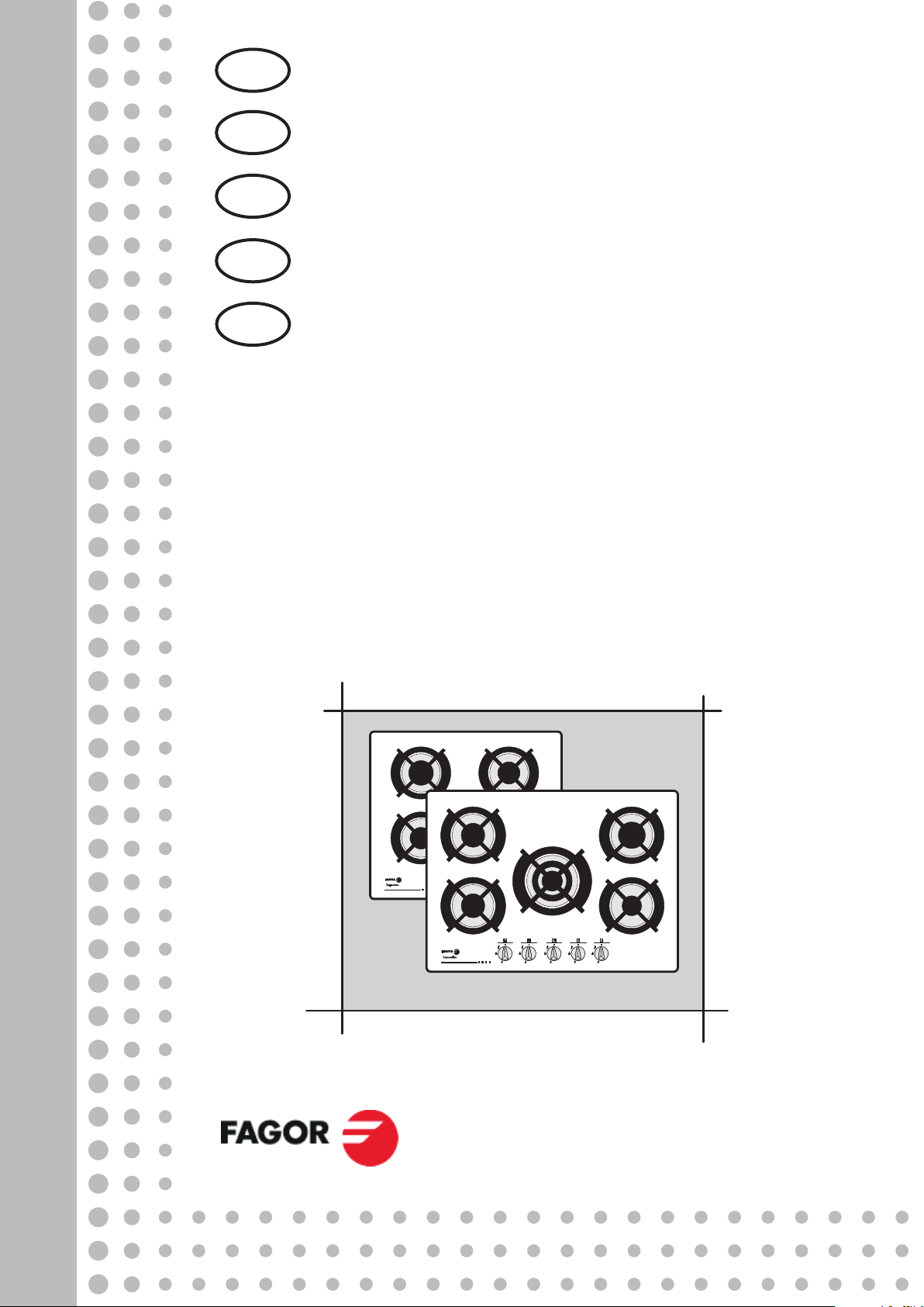
BUILT-IN HOBS
SP
PT
FR
DE
PLACAS DE ENCASTRE
CHAPAS DE FOG
TABLES ENCASTRABLES
EINBAU-GASKOCHPLATTE
AO
6CFI-5GL
6CFI-5GLST
6CFI-4GLS
6CFI-4GLSB
6CFIE-4GLS
Page 2

Dear Sirs and Madams,
You have purchased a gas hob designed to be fitted in a kitchen worktop.
Thanks to its state-of-the art technological and aesthetic solutions the gas hob
perfectly matches any interior allowing the user to arrange the kitchen room
according to his or her needs and preferences.
This hob is not equipped with controls. It is designed to work together with an
appropriate control panel or oven manufactured by our company.
The hob features gas burners and ignitors switched on by gas tap knobs.
The burners ensure complete stability of the flame, which prevents it from going
out even when it is small.
The hob is also equipped with taps with flame failure device which cuts off gas
supply to each burner when the flame has gone out eg as a result of accidental
spillage or draught.
The glass surface of the hob is very attractive and easy to maintain.
Before the first use please read this instruction manual carefully as it includes tips
and guidelines concerning the correct use of the appliance.
We hope you will be satisfied with our product.
FAGOR
EN 1
Page 3

1 GENERAL INFORMATION..............................................................................3
1.1 PURPOSE OF THE APPLIANCE..............................................................3
1.2 TECHNICAL DATA....................................................................................3
1.3 MODELS OF GAS HOBS..........................................................................4
1.4 SAFETY GUIDELINES..............................................................................4
2 INSTALATION ................................................................................................. 5
2.1 GENERAL TIPS.........................................................................................5
2.2 INSTALLATION OF THE GAS HOB.........................................................6
2.3 CONNECTING THE HOB TO GAS SUPPLY............................................7
3 THE USE OF THE BURNERS....................................................................... 11
3.1 OPERATION PRINCIPLES .....................................................................11
3.2 CHOICE OF UTENSILS........................................................................... 12
4 CLEANING AND MAINTENANCE ................................................................13
4.1 GENERAL INSTRUCTIONS....................................................................13
4.2 CLEANING THE BURNERS.................................................................... 14
5 WHAT TO DO IF THE HOB MALFUNCTIONS .............................................15
6 ENVIRONMENT PROTECTION ....................................................................17
Note:
Before using the appliance, please read this instruction manual carefully.
The appliance should be installed after 8 hours of seasoning in the kitchen
room.
The gas hob is manufactured in class I of the security against electric shock
and must be connected to the installation with working external earth circuit.
The hob should be connected to the gas system only by a properly certified
fitter of gas appliances, which should be confirmed on the product’s
warranty card. The lack of such confirmation will render the warranty null
and void!
Prior to installation, ensure that the type of gas your are supplied with is
compatible with the type of gas the hob is adjusted to. Information about the
required type of gas is stated on the rating plate of the appliance.
The appliance should be installed and used in a well-ventilated room. Keep
ventilation grates always open or install a forced ventilation system (a
cooker hood).
No amateur repairs of the appliance are permitted on pain of losing the
warranty rights.
In case of any problems with the appliance contact an authorised servicing
company idicated by the appliance manufacturer.
EN 2
Page 4
1 GENERAL INFORMATION
1.1 PURPOSE OF THE APPLIANCE
Gas hobs are equipped with an integrated control system and are designed to be fitted in a
kitchen worktop. They are designed for the preparation of meals only in a household. They must
not be used for other purposes!
1.2 TECHNICAL DATA
Table 1
Type
Characteristics
6CFI-
5GL BUT
6CFI-
5GLST
BUT
6CFI-
5GLST
NAT
6CFI4GLS
BUT
width 700 700 700 594 594 594 594
Hob's
overall
depth 575 575 575 520 520 520 520
dimensions
[ mm ]
height 48 48 48 41 41 41 41
Supply voltage 1N ~ 230V 50Hz
small∅ 45 mm /1,0
1 1 1 1 1 1 1
kW
Number
of
gasburne
rs [units]
medium∅ 65 mm /
1,75 kW
large∅ 91 mm / 3,0
kW
2 2 2 2 2 2 2
1 1 1 1 1 1 1
triple crown burner
1 1 1 — — — —
∅125 mm / 3,6 kW
Knob-controlled spark ignitors
Flame failure device
• • • • • • •
—
• • • • • •
6CFI4GLS
NAT
6CFI-
4GLSB
NAT
6CFIE-
4GLS
NAT
Hob surface
Glass
black
Glass
black
Glass
black
Glass
black
The hobs can be supplied with the following types of gas:
– natural gas 2H – (G20 20 mbar)
– LPG G30 29/37 mbar
Type of gas Small burner Medium burner Large burner
2H–(G20 20 mbar)
LPG G30 29/37
mbar
EN 3
X072 Z097 Y118 T135
050 065 085 095
Glass
black
Glass
white
Glass
black
Table 2
Three crown
burner
Page 5
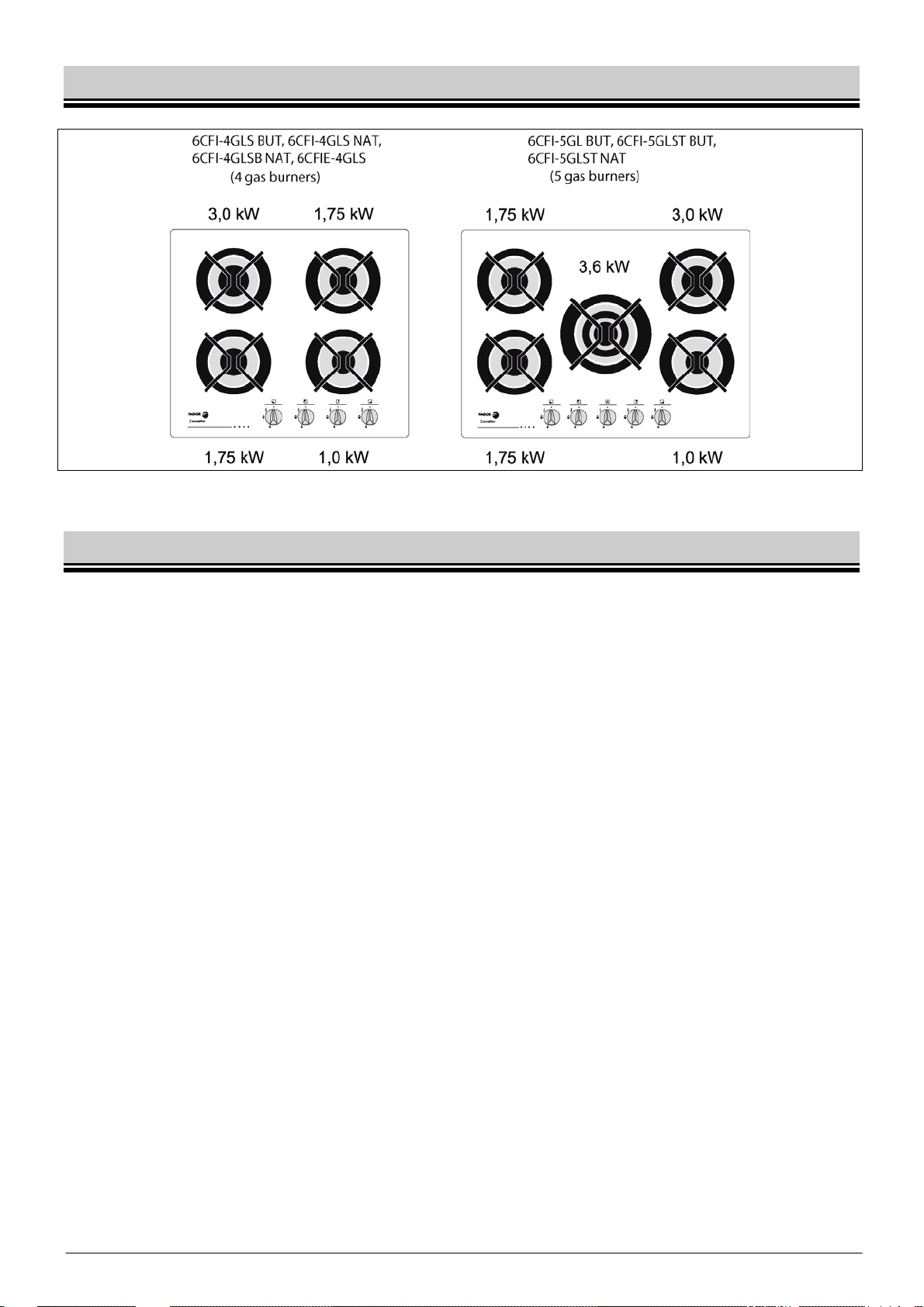
1.3 MODELS OF GAS HOBS
Fig.1
1.4 SAFETY GUIDELINES
The appliance should be operated by adults only; do not allow children to play nearor
fiddle with the hob.
The appliance should be installed in compliance with the relevant laws in force and with
the instructions contained in this manual. Do not install the appliance near flammable
materials such as curtains, towels etc.
After the appliance is switched off, the ovens, electric plate, pan supports and pans with
food remain hot for quite some time. Please pay special attention to children and do not
allow them to come near the hob or touch the pans placed on it.
Ensure that the cables of other household appliances used near the working appliance
are far from hot burners and electric plate.
Always use protective gloves when removing items from the hob.
Do not plac e dented or unstable pans on pan supports as they may topple over and flood
the burners or plate.
Never leave the appliance with lit burners unattended, particularly when frying, as
overheated fat may catch fire
Before removing the pans from the burners reduce the flame or switch it off completely.
Never use the appliance as a room heater.
In the event of the escape of gas:
– immediately close the valve on the gas supply system or cylinder,
– ventilate the room thoroughly,
– call gas emergency service.
In the meantime DO NOT!
– light matches, smoke cigarettes,
– turn on or off electric appliances (radio, doorbell, light switch) or mechanic
appliances generating sparks
If the gas escaping from a leaky gas cylinder valve catches fire
– place a wet blanket on the cylinder to cool the cylinder down,
– close the cylinder valve.
EN 4
Page 6
DAMAGED CYLINDER MUST NOT BE USED !!
The failure should be reported to an authorised servicing company
DO NOT:
– place a large pan on two burners,
– use the hob in a room without effective ventilation,
– make any unauthorised adjustments of the hob to a different type of gas
orchanges in the appliance’s gas and electric system; any modifications of the
appliance cause danger to the user,
– make any unauthorised repairs;
– use the appliance with a damaged cable or plug,
– allow young children and people who have not read this manual to use the hob.
The manufacturer disclaims all liability for any injury or damage resulting from the
improper operation of the appliance or its improper use or actions violat-ing the
instructions of this manual.
2 INSTALATION
2.1 GENERAL TIPS
The manufacturer is not liable for damages resulting from non-compliance with
standards and regulations in force and from the installation of the hob by an
unauthorised person.
1. The appliance should be installed in a kitchen room that meets the following requirements:
– appropriate size ensuring that the maximum heat output from the installed gas
appliances does not exceed 930 W/m3,
– a minimum height of 2.2 m,–ventilation system in good working order (ensuring
that the air is exchanged at least 1.5 times per hour),
– ensured supply of air (if there is no window) through holes made in external walls
with the area of at least 0.016 m2,
– ensured removal of fumes eg through a working chimney duct with a minimum
side of 0.14 m.
2. In order to limit the negative influence of draughts on the operation of burners, do not
install the hob on a window-door axis.
3. The appliance should be installed in a kitchen worktop not higher than 850 mm. The
room wall adjacent to the hob should be made of non-flammable materials (fig. 2).
EN 5
Page 7
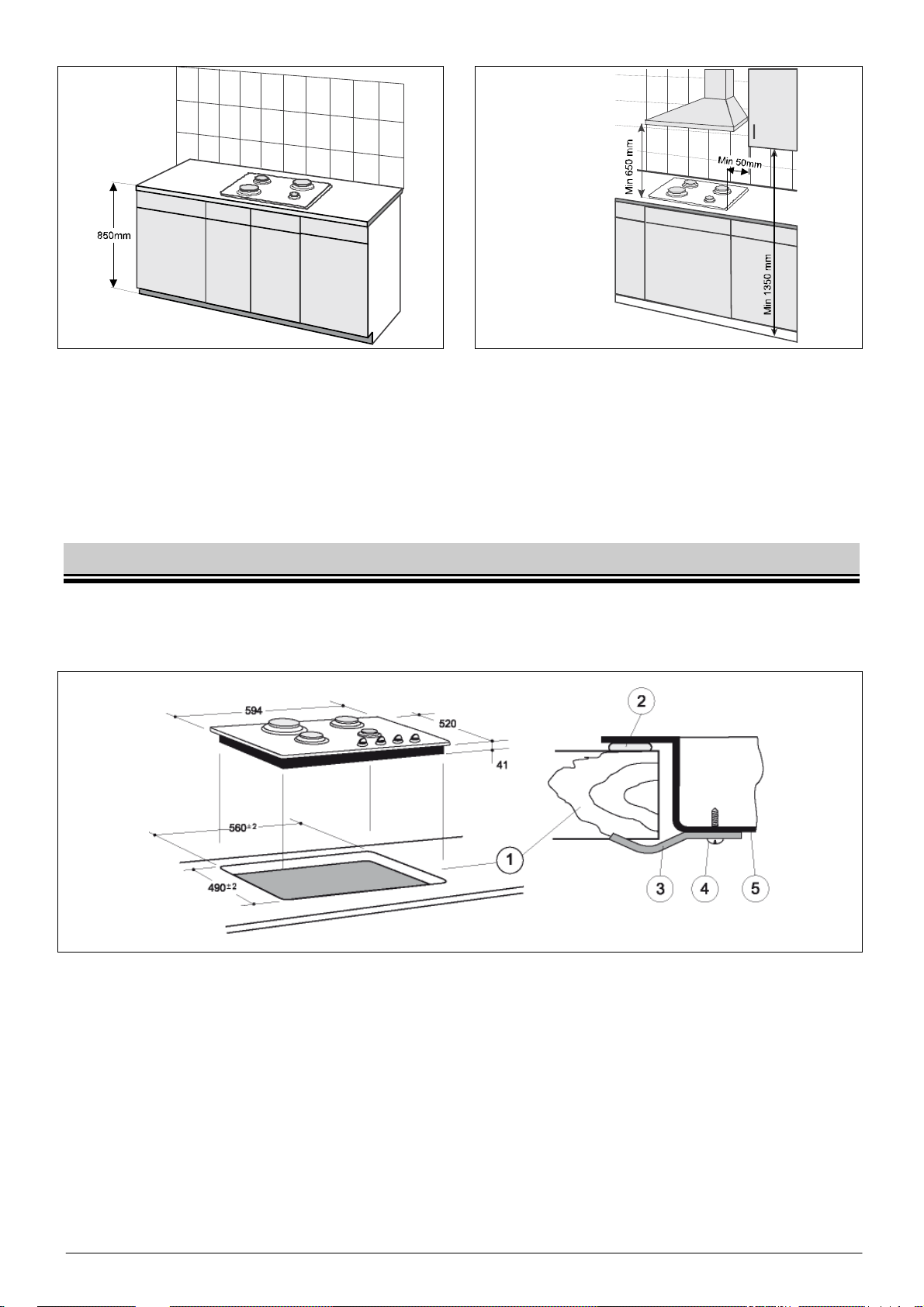
Fig.2 Fig.3
4. There should be an open space above the hob to allow kitchen odours to disperse.
Installation of a cooker hood is recommended to either absorb or extract the odours.The
distance between the hob and the hood should not be shorter than 650 mm (fig.3).
5. .Do not fit kitchen cabinets directly over the hob. The distance between the hob's side
edges and the side edges of hanging cabinets should not be shorter than 50 mm (fig.3)
2.2 INSTALLATION OF THE GAS HOB
1. Before the installation, please check the measures of the hob and the opening in the
worktop where the hob is going to be installed.
Fig.4
2. Cut out a rectangular 490 x 560 mm hole in the worktop 1 (fig. 4).
3. Remove the backing paper from the provided sealing gasket.
4. Place the hob face down and affix the sealing gasket 2 all around the hob (fig. 4 and 5)
5. After affixing the gasket place the hob in the cavity in the worktop 1 and press down
tightly so that sealing joint is perfectly closed
6. Fix the hob underneath to the worktop 1 with clamps 3 and screws 4 supplied in the
accessory bag
7. Shelf "A" (fig. 6) should be installed under the worktop to protect the user from
accidentally touching the hot hob from beneath. The shelf should be fitted after installing
the hob in the worktop.
EN 6
Page 8
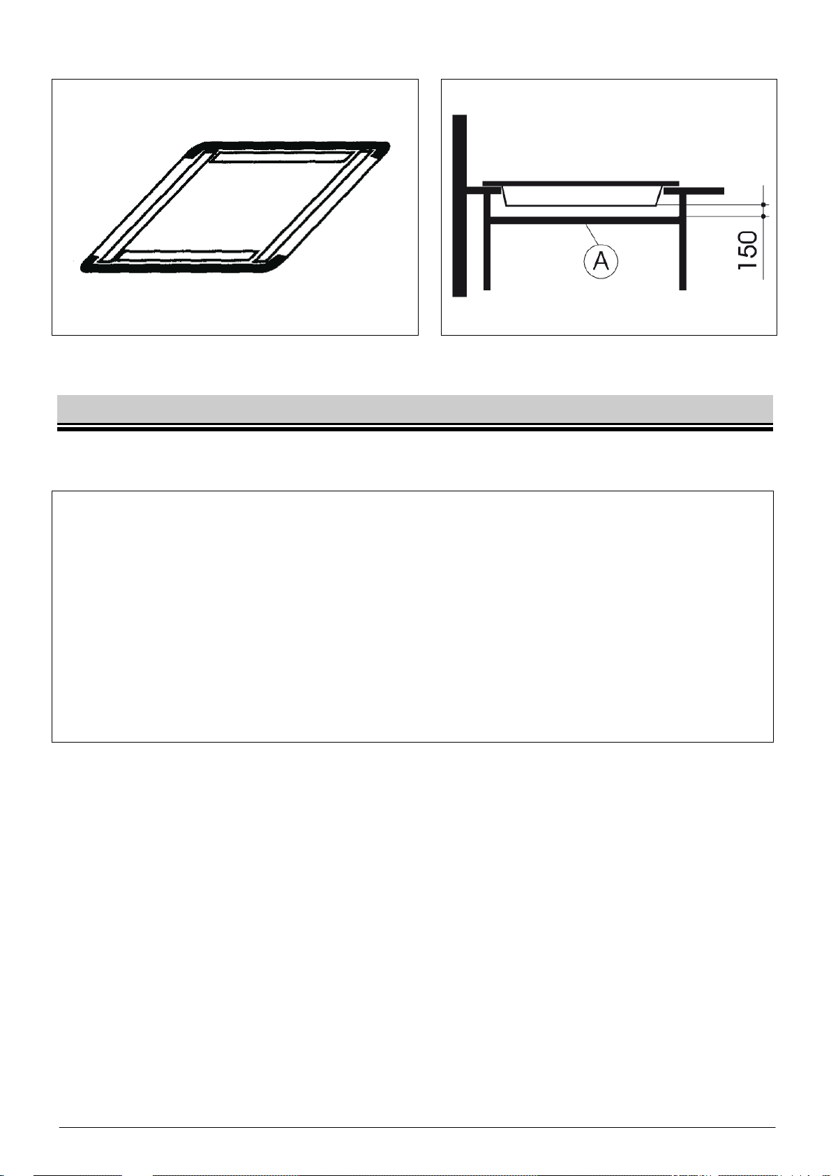
Fig.5 Fig.6
2.3 CONNECTING THE HOB TO GAS SUPPLY
Having installed the hob in the worktop, connect the appliance to internal gas supply system.
Note:
1. The connection of the hob to the gas supply system should be made in
accordance with the regulations in force.
2. All activities involved in connecting the hob to the gas supply system, adjusting
the taps and replacing nozzles should only be performed by a properly certified
person
3. Before beginning the connection operation make sure that the gas valve is
closed!
4. Incorrect connection and tension of the system may cause malfunction or even
damage of the hob or gas supply system.
5. The manufacturer disclaims all liability for any
The gas hob is equipped with 1/2" connector pipe. Gas supply sy stem should be connected to
the pipe with appropriate fittings.
CONNECTING THE HOB TO NATURAL GAS SUPPLY
When connecting the hob to natural gas supply use an elbow with gasket and seal the taper
thread (at the outlet) with Teflon band. The hob may be connected to the internal supply system
with a rigid connection or a flexible metal tube. The connection method is shown in fig. 7.
EN 7
Page 9
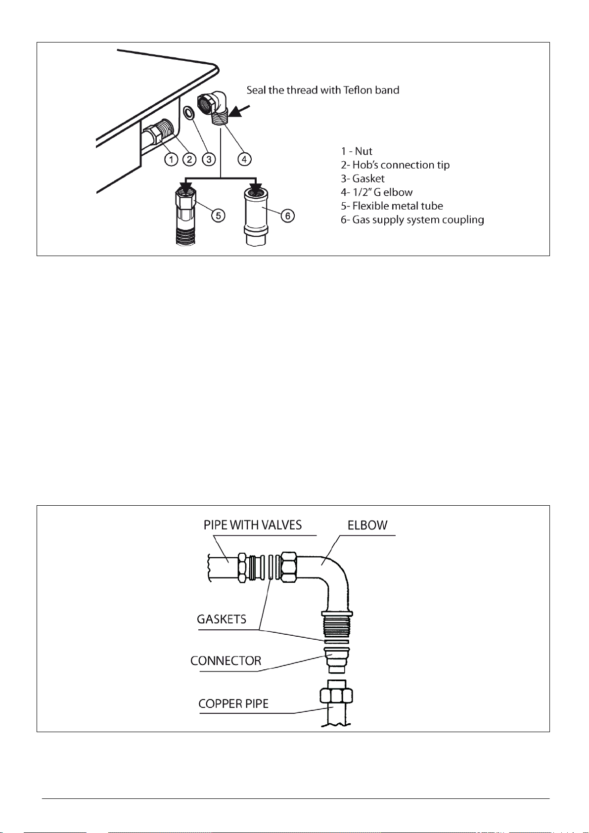
Fig. 7
CONNECTING THE HOB TO AN LPG CYLINDER
Do not install the appliance in the basement or in any other room whose floor is below
the ground level as LPG is heavier than air and accumulates at the floor level.
The cylinder should be located in an easily accessible place, positioned vertically and
secured against falling over.
When connecting the appliance to the cylinder use a flexible tube.
To connect the appliance use the LPG tip with a gasket as shown in fig. 8.
Each time after connecting the hob to LPG cylinder check the soundness on high
pressure side, check the cylinder valve for soundness and the connection of regulator
with the cylinder and its operation.
The soundness of all connections and the cylinder valve maybe pre-checked by apply ing
soap solution on the said points with the normal working pres-sure. Appearing bubbles
signal the escape of gas.
Fig.8
EN 8
Page 10
Note:
1. Under no circumstances can the gas soundness be checked by means of a naked
flame (e.g. with a match or candle). Danger of explosion!
2. Regularly, every six months, check the condition of the tube and soundness of its
connection to the end elements.
REPLACING THE NOZZLES
Note:
1. Before replacing the nozzles and adjusting gas taps remove the cable plugfrom
the mains supply .
2. When adjusting the taps do not unscrew the needle completely.
The hob is adjusted to the type of gas and pressure stated on the appliance's rating plate.
In the event of a change of the type of gas replace the nozzles and adjust the taps.
Before beginning these activities you must:
– shut down the cock shutting off the gas
supply system or cylinder from the
hob,-shut down all the taps in the hob,
disconnect the hob from the mains.
–
Then:
– remove the burners' lids and rings,
remove the nozzles with socket wrench
–
no. 7 and replace them with new ones
in accordance with table2,
put burners' rings and lids back,-
–
adjust the taps and check the
–
connections for soundness
Fig.8
ADJUSTING THE TAPS
The adjustment of a gas tap consists in setting the burner flame in the simmering position. To
adjust the taps remove all the knobs and control panel.
Then:
– open the gas flow with a knob and light the adjusted burner,
– set the knob in the simmering position . and then, without changing that position,
remove it from the tap's mandrel
– put a screwdriver in opening 'A" or mandrel opening "B" (depending on the type of the tap
fig. 10) and turn it, observing the flame, to achieve such a size of the flame that will
prevent it from being extinguished in a slight draught or during the operation of quick
switching from the full to the simmering position . of the flame and back; the
adjustment is correct when the core of the flame is cone-shaped in green and blue colour
and is ca. 2 - 4mm tall,
EN 9
Page 11
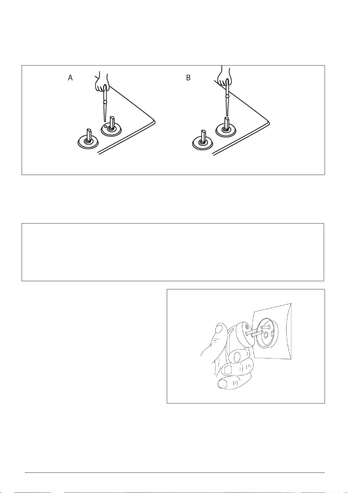
– if there are perceptible changes of gas pressure in the gas supply system, the simmering
flame should be set at the low pressure in the system to prevent the burner from
extinguishing during normal use.
– after adjusting the taps put the knob back in its position and turn off the flame.
Fig. 10
CONNECTING THE HOB TO THE MAINS
The appliance is supplied with the mains cable without a plug.
Note:
1. The plug should be connected to the mains cable only by a properly certified
installer- electrician.
2. The mains socket should be easily accessible to the user.
3. Please make sure that feed cable does not touch hot burners when the hob is
working.
The hob is adjusted to alternating cur-rent
230V, 50Hz, and should be connected to the
mains socket equipped with properly
connected ground contact.
Connecting the hob to a socket without the
ground contact causes a danger of electric
shock in the even of a failure of the hob's
electric system
Fig.11
EN 10
Page 12

3 THE USE OF THE BURNERS
Before switching on a burner make sure that
the knob you are going to use corresponds to
the burner you wish to switch on
3.1 OPERATION PRINCIPLES
THE USE OF THE BURNERS
Do not remove pan supports and place pans directly on burners.
Do not open the gas supply system valve or cylinder valve without making sure that all
taps are closed.
The tips of ignitors and thermocouples should always be kept clean and dry to ensure
their correct functioning.
Do not touch hot burners or hotplate, pan supports or pans placed on them.
Do not hit the taps, burners, hotplate, ignitors or thermocouple tips.
Prevent spillage and the flooding of burners and hotplate.
In the case of hobs with flame failure device please remember to keep the knob pressed
ca. 10s longer after lighting the burner for the device to become activated.
Do not overload the pan supports.
Correct and power-efficient use of burners can be ensured by
– setting a proper size of the flame
– correct choice of utensils.
Fig. 12
SELECTING THE FLAME
The flow of gas in individual burners is opened by means of gas taps' knobs.
The flame should not lick around from the bottom of a pan but cover only 2/3 of its
surface. This will reduce the gas consumption and prevent the flame from soiling the
utensils.
EN 11
Page 13

The size of the flame depends on the position of the knob (fig. 13). The full flame should be
used until the dish begins to boil, then it is better to use the simmering flame. The size of the
flame should be regulated only within the range between
Fig.13
TURNING THE BURNERS ON AND OFF
Turning the burners on
– push in the knob of selected burner to the maximum, turn it in the counter-clockwise
direction, set it in position and keep it pressed until the flame appears;
– after the burner lights release the press on the knob; the burner should remain lit,
– when the burner has lit keep the knob pressed for ca. 10s more for the flame failure
device to become activated,
– if the flame goes out r epeat the activities described above but keep the knob pressed for
ca. 5s longer
– set the required size of the flame.
Turning the burners off
– to turn off the burners, turn the knobs clockwise to zero position.
Hobs supplied from a LPG cylinder
Before lighting the first burner, open the valve on the LPG cylinder. Then light the burner using
the method described above.
When closing the flow of gas before turning off the last burner:
– close the valve on the LPG cylinder,
– when the flame has gone out, close the tap of that burner.
When the hob is not used the valve of the LPG cylinder should be closed
and . .
3.2 CHOICE OF UTENSILS
Pots used for cooking on the hob should not be too tall, ideally their height should equal
2/3 of the diameter of their bottom.
Utensils should be always clean and dry as they will then conduct and retain heat well.
During cooking, pan lids should be used, which will prevent the excess of odours from
accumulating in the kitchen.
EN 12
Page 14

Minimum diameters of pans for each type of burner:
– for a small burner∅ 90 mm
– for a medium burner∅ 120 mm
– for a large burner∅ 140 mm
– for a double burner∅ 180 mm
4 CLEANING AND MAINTENANCE
Note:
Before cleaning the appliance switch off the hob at the mains supply.
4.1 GENERAL INSTRUCTIONS
Clean the hob regularly to ensure its proper technical condition and aesthetic appearance.
When cleaning the hob and knobs do not use harsh abrasives, sharp objects, wire pads,
powders and caustic cleaners
Before cleaning the hob remove pan supports and top elements of burners.
Clean the enamelled surface of burner housing with a cloth or sponge wetted with warm
water with delicate detergent, avoiding any excess of water. Remove persistent stains
with special cooker cleaners.
When cleaning the hob do not allow water to get beneath the hob. Ensure that the hob
surface, particularly the housing around the burners, is always clean. It is important as
during normal use dirt accumulating in the clearance between the burners' rings and the
burner's housing deteriorates the combustion of gas.
Put dirty pan supports in warm soapy water for some time, then wash and dry them.
Cleaning glass hobs:
– To remove remnants of food from the hob use a wooden spatula or a special tool (fig.16),
taking care not to scratch the glass surface of the hob.
– Materials that can melt, such as aluminium foil or plastics should be kept away from the
burners. However, if such materials happen to melt on the hob, they should be removed
EN 13
Page 15

from the hob immediately (when they are still hot). Act similarly if any liquid including a lot
of sugar spills; on the hot hob surface sugar melts very quickly, which may result in
permanent stains. Discolouring of the hob does not affect its proper functioning
– After cleaning, the hob may be covered with a protection agent, eg CERA FIX
Fig.15
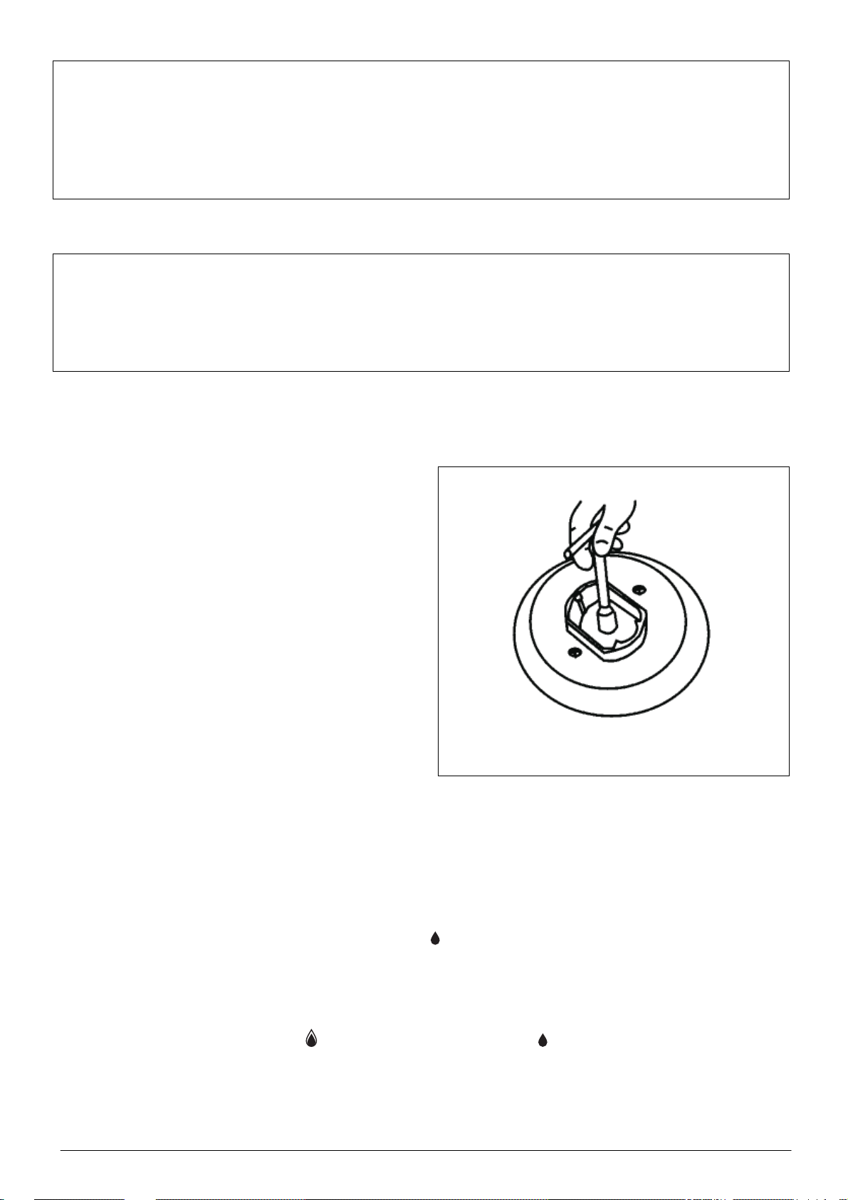
4.2 CLEANING THE BURNERS
Gas burners, ignitors and thermocouple tips should be cleaned after each spillageand
regularly to remove cooking residuals and dirt.
To clean burners remove the lids 1 and
rings 2 (Fig. 16), put them in warm water
with detergent for some time and then
wash each part of the burner separately.
Clean the lid with a sponge or brush and
the ring - with a plastic brush or a soft wire
brush. Remove dirt from burner ports with
a steel wire. After cleaning check if the
burner ports are clear.
1
2
4
3
Fig.16
EN 14
Page 16

Ensure that the burner body, particularly
near the nozzle, is always clean. Dirt
accumulating around the nozzles 3 (fig.16)
may clog it, as a result of which the burner
will not light or will light only with a faint
flame. To clean the nozzles use a brush
soaked in solvent (fig. 17).
Fig.17
Dry the cleaned burners carefully as wet
elements may not light or cause the gas to
combust improperly. Assemble dry burners
carrying out the disassembling steps in the
reverse order, taking care not to damage
the ignitors and thermo-couples' tips.
Fig.18
5 WHAT TO DO IF THE HOB MALFUNCTIONS
During use some malfunctions of the hob may occur. The user can make small repairs
without calling a qualified technician, following the guidelines stated in table3.
In the warranty period all repairs except for the ones specified below should be carried out
by the authorised Servicing Point.
After the warranty period ends the user should request the servicing point to conduct
periodical inspections of the appliance.
EN 15
Page 17

Symptoms Cause What to do
- Close burners’ taps
- Close the shut-off valve on the system, before the hob
Not clear burner ports
The burner
does not light
Blocked (flooded )
nozzle
- Air the room
- Remove the elements of the burner, clean them and
clear the burner ports
- Assembly the burner correctly and try to light it again
- Remove all the elements of the burner
- Clean the nozzle and, if necessary, use a thin copper
wire (do not use steel wire or drill the hole )
Table 3
The igniter does
not light the
burner (no
spark)
A break in the electric
system
Dirty burners and/or
ignitors
- check the fuses- if any fuse is burnt, replace it
- clean and dry the burners and ignitors thoroughly
Note:
1. If after the above-specified steps have been taken the appliance still does not
work properly, contact the nearest authorised servicing company.
2. A faulty gas hob should not be used until it is repaired by qualified servicing
personnel.
3. If the appliance is not going to be used for a longer time period, clean it
thoroughly, close the valve before the hob and pull the feed cable plug from the
mains socket.
EN 16
Page 18

6 ENVIRONMENT PROTECTION
This appliance is marked with a symbol of a crossed out wheeled bin in compliance with the
European Directive 2002/96/EC.
This symbol means that the appliance, when its economic life is over, must not be stored
together with other house hold waste. The user is obliged to deliver it to appropriate
organizations collecting electrical and electronic waste. Correct handling of electrical and
electronic waste helps to avoid harmful consequences for people and natural environment
resulting from incorrect
EN 17
Page 19

Estimados Clientes!
Acaban de adquirir una placa de cocción de gas destinada a serencastrada en la
mesa de trabajo de cocina.
Gracias a las modernas soluciones técnicas y a sus valores estéticosla placa de
gas se integra con armonía en el interior de cualquier cocina,permitiendo disenar
dicho interior en función de las necesidades y gustosdel usuario.
La placa no dispone de control. Está adaptada a trabajar con un panelde control
adecuado o un horno de nuestra empresa.
La placa está provista de quemadores de gas con encendido integradoen los
mandos de los grifos de gas.
Los quemadores garantizan estabilidad total de la llama, por lo que lallama no se
apaga incluso cuando es pequena.
La placa está también provista de grifos con seguridad corte de gas,que corta la
alimentación de gas a todos los quemadores en caso deextinción de la llama,
causada por ejemplo por un desbordamientoaccidental o una corriente de aire.
La superficie en vidrio tiene altos valores estéticos y es fácil mantenerla limpia.
Antes de empezar a utilizar este aparato le rogamos leacuidadosamente las
presentes instrucciones, que incluyen lasrecomendaciones e indicaciones para el
uso correcta de la placa.
Les damos gracias por la compra de nuestro producto y les deseamos mucha
satisfacción de su uso.
FAGOR
SP 18
Page 20

1 DESCRIPCION GENERAL............................................................................ 20
1.1 DESTINACION DEL PRODUCTO........................................................... 20
1.2 DATOS TECNICOS.................................................................................20
1.3 MODELOS DE PLACAS DE GAS........................................................... 21
1.4 INSTRUCCIONES DE SEGURIDAD.......................................................21
2 INSTALACION...............................................................................................23
2.1 INSTRUCCIONES GENERALES ............................................................23
2.2 MONTAJE DE PLACA DE GAS.............................................................. 24
2.3 CONEXION DE LA PLACA A LA INSTALACION DE GAS ...................25
3 UTILIZACION DE LOS QUEMADORES .......................................................28
3.1 NORMAS DE UTILIZACION.................................................................... 28
3.2 SELECCION DE RECIPIENTES .............................................................30
4 LIMPIEZA Y MANTENIMIENTO.................................................................... 31
4.1 INSTRUCCIONES GENERALES ............................................................31
4.2 LIMPIEZA DE QUEMADORES ...............................................................32
5 ANOMALIAS EN EL TRABAJO DE LA PLACA...........................................33
6 PROTECCIÓN DEL MEDIO AMBIENTE.......................................................34
Advertencias:
Antes de empezar a utilizar el aparato rogamos lea atentamente el
presentemanual de instrucciones.
Instale el aparato después de 8 horas de su previo reposo en la cocina.
La placa de gas ha sido fabricada conforme con los requisitos de la I clase
deprotección contra choque eléctrico y requiere conexión a una instalación
provistade un circuito de protección externo que funcione correctamente.
La conexión a la instalación de gas deberá ser efectuada exclusivamente
por unautorizado especialista en instalación de aparatos de gas, el hecho
que deberá serconfirmado el la hoja de garantía del producto. ¡Falta de
dicha confirmaciónsignificará la invalidación de la garantía!
Antes de la instalación asegúrese de que el tipo de gas disponible sea
compatiblecon los ajustes de fábrica del aparato. La información del tipo de
gas se encuentraen la placa de características del aparato.
El lugar de instalación del aparato debe disponer de una eficiente
ventilación deadmisión y evacuación de aire. Mantenga las rejillas de
ventilación siempreabiertas o instale un sistema de ventilación forzada
(campana de extracción).
Queda prohibido realizar cualquier reparación por su propia cuenta bajo el
rigor depérdida de derechos de garantía.
En caso de producirse alteraciones en el trabajo del aparato póngase en
contactocon el servicio de atención técnica indicado por el fabricante del
aparato.
SP 19
Page 21

1 DESCRIPCION GENERAL
1.1 DESTINACION DEL PRODUCTO
Las placas de gas están provistas de un sistema de control integrado y están preparadaspara
su integración en los muebles de cocina. Han sido disenadas exclusivamente para
usodoméstico y preparación de alimentos. ¡No está permitido su uso con otros fines!
1.2 DATOS TECNICOS
Tipo
Características
Dimensiones de
laplaca
[mm]
Tensión nominal de
alimentación
Número
dequema
dor-es de
gas[unida
des]
ancho 700 700 700 594 594 594 594
profundo 575 575 575 520 520 520 520
alto 48 48 48 41 41 41 41
quemador
pequeno∅ 45 mm /
1,0 kW
quemador
mediano∅ 65 mm /
1,75 kW
quemador
grande∅ 91 mm /
3,0 kW
quemador
triplecorona∅ 125
mm / 3,6 kW
6CFI5GL
BUT
1 1 1 1 1 1 1
2 2 2 2 2 2 2
1 1 1 1 1 1 1
1 1 1 — — — —
6CFI5GLST
BUT
6CFI5GLST
NAT
1N ~ 230V 50Hz
6CFI4GLS
BUT
6CFI4GLS
NAT
6CFI4GLSB
NAT
6CFIE4GLS
NAT
Encendido eléctrico de
chispasincorporado en los
mandos
Seguridad corte de gas —
Mesa de trabajo
• • • • • • •
de
vidrio,
negra
• • • • • •
de
vidrio,
negra
de
vidrio,
negra
de
vidrio,
negra
de
vidrio,
negra
de
vidrio,
blanca
de
vidrio,
negra
SP 20
Page 22

Las placas están preparadas para alimentación con los siguientes gases combustibles:
-gas natural 2H-(G20 20 mbar)
-3 B/P G30 29/37 mbar
Tabla 2
Tipo de gas
2H-(G20-20 mbar) X072 Z097 Y118 T135
3B/P-(G30 29mbar) 050 065 085 095
Quemador
pequeno
Quemador
mediano
Quemador
grande
Quemador triple
corona
1.3 MODELOS DE PLACAS DE GAS
Fig.1
1.4 INSTRUCCIONES DE SEGURIDAD
El aparato deberá ser operado exclusivamente por personas adultas; no permita quelos
ninos manejen los mandos o jueguen con la placa.
El aparato debe ser instalado de acuerdo con las regulaciones en vigor y
lasrecomendaciones incluidas en el presente manual. No debe instalarse cerca de
objetosinflamables, por ejemplo cortinas, toallas, etc.
Tras apagar el aparato los quemadores, la placa eléctrica, la parrilla y los recipientescon
alimentos mantienen su alta temperatura durante un tiempo bastante largo.
Presteatención especial a los ninõs. Manténgalos siempre alejados del aparato y no
lespermita tocar los recipientes que están en la placa.
Mantenga los cables de conexión de otros aparatos electrodomésticos utilizadosdurante
la operación de la placa alejados de los quemadores calientes y de la placaeléctrica.
Utilice guantes de protección para quitar los recipientes con alimentos de la placa.
No sitúe recipientes deformados o inestables en las parrillas, porque éstos
podráncaerse y derramar los alimentes sobre los quemadores y la placa.
SP 21
Page 23

No deje el aparato con los quemadores encendidos sin supervisión, en particular a
lahora de freír, dado que la grasa sobrecalentada es fácilmente inflamable.
Antes de quitar los recipientes de los quemadores disminuya la llama o
apáguelacompletamente.
No utilice placa para calentar habitaciones.
Avant de nettoyer la table il faut retirer les grilles et les éléments des brûleurs
En caso de fugas de gas HAY QUE:
– cerrar inmediatamente la válvula de instalación de gas o en la bombona de gas,
– ventilar bien el local,
– llamar a Urgencias de Gas.
Durante este tiempo ¡ESTA PROHIBIDO!
– encender fósforos, fumar cigarillos,
– encender o apagar aparatos eléctricos (por ejemplo radio, timbre, interruptoresde
alumbrado) o dispositivos mecánicos que produzcan chispas.
En caso de inflamación de gas presente por fuga en la válvula en la bombona de
gasHAY QUE:
– echar una manta mojada en la bombona para enfriarla,
– cerrar la válvula de la bombona.
¡¡¡ESTA PROHIBIDO EL USO DE BOMBONAS DEFECTUOSAS!!!
Es necesario avisar el servicio de atención técnica autorizado sobre la avería.
ESTA PROHIBIDO:
– poner un recipiente grande sobre dos quemadores a la vez,
– utilizar la placa en un lugar donde no haya ventilación eficiente,
– efectuar modificaciones propias en la placa, tales como su adaptación a
otrotipo de gas, cambios en la instalación eléctrica y de gas, etc.
Cualquiermodificación de este tipo supone un riesgo para el usuario
– efectuar reparaciones por su propia cuenta,
– utilizar el aparato con cable o clavija defectuosos,
– permitir el uso de la placa por ninos o personas que no conozcan el
presentemanual de instrucciones.
El fabricante declina toda la responsabilidad por los eventuales danos personalesy
materiales que resulten de la manipulación inadecuada de la placa de gas, de suuso no
conforme a su destinación o una actuación no conforme al manual deinstrucciones.
SP 22
Page 24

2 INSTALACION
2.1 INSTRUCCIONES GENERALES
El fabricante declina toda responsabilidad por los danos que hayan resultado de no cumplircon
las normas y regulaciones vigentes o de la conexión de la placa por una persona noautorizada.
1. La cocina donde se va a instalar el producto tiene que cumplir con unos
requisitosdeterminados.Por lo tanto, dicho local debería tener:
– volumen adecuado, que garantice que la carga térmica proveniente de
losaparatos de gas no sobrepase 930 W/m3,
– altura mínima de 2,2 m,
– eficiente ventilación de admisión y evacuación de aire (intercambio mínimo de1,5
de volumen de aire en una hora),
– en caso de que no haya ventanas, admisión de aire garantizada por unoshuecos
en los muros exteriores de superficie mínima de 0,016 m2
– evacuación de los productos de combustión garantizada, por ejemplo por
uneficiente conducto de chimenea de lado mínimo de 0,14 m.
2. Para disminuir la influencia negativa de corrientes de aire en el funcionamiento de
losquemadores no se debe instalar la placa en la línea ventana-puerta.
3. El aparato deberá instalarse en la mesa de trabajo de altura no mayor a 850 mm.
Lapared adyacente a la placa estará hecha de materiales incombustibles (fig. 2).
Fig.2 Fig.3
4. Por encima del aparato debe haber un espacio libre para la evacuación de
vaporessiendo efectos de cocción. La distancia entre la campana extractora y la placa
deberáser de 650 mm como mínimo (fig. 3).
5. Está prohibido colgar armarios de cocina directamente por encima de la placa.
Ladistancia mínima entre los bordes laterales de la placa y los bordes laterales de
losarmarios de cocina será de 50 mm como mínimo (fig. 3).
SP 23
Page 25

2.2 MONTAJE DE PLACA DE GAS
1. Antes de proceder al montaje verifique todas las dimensiones de la placa y el agujeroen
la mesa de trabajo donde va a instalarse la placa.
Fig.4
2. Corte un agujero rectangular de dimensiones 490 x 560 [mm] en la mesa de trabajo(fig.
4).
3. Retire el papel de protección de la junta
4. Coloque la placa boca abajo y pegue la junta 2 en todo su perímetro (fig. 4 y 5).
5. Tras haber pegado la junta coloque la placa en el hueco en la mesa de trabajo
1presionando bien para que la junta 2 esté bien adherida a la mesa de trabajo.
6. Amarre la placa en la mesa de trabajo 1 por la parte inferior, sirviéndose de enganches3
y tornillos 4, los cuales encontrará en la bolsa de accesorios.
7. Por debajo de la mesa de trabajo instale estante "A" (fig. 6), asegurando de estaforma
que el usuario no toque por casualidad la placa caliente por la parte inferior.Una vez
instalada la placa en la mesa de trabajo se fijará el estante..
Fig.5 Fig.6
SP 24
Page 26

2.3 CONEXION DE LA PLACA A LA INSTALACION DE GAS
Una vez empotrada la placa en el mueble se procederá a su conexión a la instalación degas
interior.
Advertencias:
1. Conexión de la placa a la instalación de gas debe efectuarse cumpliendo
lasregulaciones en vigor.
2. Las operaciones relacionadas a la conexión de la placa a la instalación de
gas,ajuste de los grifos y cambio de inyectores deben ser realizadas por
personasautorizadas exclusivamente.
3. !Es imprescindible que antes de proceder a la instalación el grifo de gas
estécerrado!
4. Una instalación hecha mal y demasiado tensada puede causar trabajo
incorrectode la placa, e incluso dano de la placa o la instalación de alimentación
de gas.
5. El fabricante declina toda responsabilidad por los danos del aparato o de
lainstalación de gas en el local, derivados de una conexión imperfecta.
La placa de gas está provista de un racor de tubo de diámetro 1/2". Al dicho racor hayque
conectar el gas, utilizando los accesorios adecuados.
CONEXION DE GAS NATURAL
Para conectar la placa al gas natural es necesario utilizar un codo con junta y estancar
larosca cónica utilizando cinta de teflón (en la salida).
Es posible conectar la placa a la instalación interior de forma rígida o sirviéndose de untubo
metálico flexible.
La forma de conectar se puede observar en fig. 7.
Fig. 7
CONEXION A BOMBONA DE PROPANO-BUTANO
No se puede instalar el aparato en sótanos o cualquier otro local donde el suelo
seencuentre por debajo del nivel de tierra, dado que el gas líquido es más pesado queel
SP 25
Page 27

aire y se acumulará en el nivel del suelo. La bombona se situará en un lugar fácilmente
accesible, en posición vertical y protegidade forma que no se caiga.
Para conectar el aparato a la bombona se utilizará un tubo flexible.
Para efectuar la conexión se utilizará un terminal para gas líquido con junta (ver fig.8).
Cada vez al conectar la placa a bombona de gas se verificará la estanqueidad por
laparte de alta presión, es decir, la estanqueidad de la válvula en la bombona así comol
a unión del reductor con labombona y su funcionamiento.
La estanqueidad de todas lasconexiones y de la válvula en labombona se puede
comprobar deforma provisional lubricandodichas zonas con agua jabonosa,bajo la
presión de trabajo normal.Aparición de burbujas demuestra fugas de gas.
Fig.8
Attention :
1. Está prohibido verificar la estanqueidad utilizando fuego abierto (por
ejemplofósforos o velas). !Peligro de explosión!
2. Deberá verificar periódicamente (cada seis meses) las condiciones del tuboy la
estanqueidad en la unión del mismo con los terminales.
CAMBIO DE INYECTORES
Nota:
1. Antes de proceder a cambiar los inyectores y ajustar los grifos desenchufe
elaparato.
2. Al ajustar los grifos no desenrosque la aguja del todo.
La placa está preparada para el tipo de gas y presión indicados en la placa decaracterísticas
del aparato.En caso de cambio de gas es necesario cambiar los inyectores y ajustar los grifos.
SP 26
Page 28

Antes de proceder a dichas operaciones es
absolutamente necesario:
– cerrar el grifo que separa lainstalación
de gas o la bombonade la placa,
– cerrar todos los grifos de la placa,
– desenchufar la placa.
– disconnect the hob from the mains.
A continuación:
– quite las tapas y difusores de gasdel
quemador,
– desmonte los inyectores utilizandollave
de tubo no. 7 y sustituya losinyectores
por otros nuevos, segúntabla 2,
– coloque los difusores de gas ytapas
quemador,
– ajuste los grifos y verifique
laestanqueidad de cada conexión
Fig.8
AJUSTE DE GRIFOSEl ajuste de grifos consiste en la regulación de la llama económica del
quemador. Paraefectuar lo dicho siga las instrucciones:
– gire el mando para abrir el paso de gas y encienda el quemador que quiere
regular,
– ponga el mando en la posición (llama económica) y retírelo de la espiga del
grifo,sin cambiar la posición del mando,
– introduzca el destornillador en el agujero "A" o en el agujero en la espiga "B"
(segúnel tipo de grifo, véase fig. 10) y gírelo, observando la llama del quemador.
Regule laaltura de la llama de manera que la llama no se apague por una
corriente de aireligera o al pasar rápidamente de la llama grande a la
económica y al revés. Elajuste se puede dar por correcto cuando el núcleo de
la llama tenga una forma decono de color verde azul y de altura de 2-4mm, en el
caso de que haya oscilacionesvisibles de presión de gas en la instalación de
alimentación de gas, la llama económicase ajustará para la presión baja de la
instalación,de forma que el quemador no seapague durante su utilización normal.
– una vez ajustados los grifos,vuelva a colocar el mando y apague la llama.
Fig. 10
SP 27
Page 29

CONEXION DE LA PLACA A LA INSTALACION ELECTRICA
La placa de gas está provista de un cable de conexión que no lleva clavija.
Nota:
1. Solamente un instalador eléctrico autorizado podrá conectar la clavija al cablede
alimentación de la placa.
2. El enchufe al que vaya conectado el aparato será fácilmente accesible para
elusuario.
3. Recuerde que durante la utilización de la placa el cable de alimentación nodeberá
tocar a los quemadores calientes.
La placa está preparada paraalimentación de
corriente alterna detensión 230V, 50Hz y
deberá serconectada a un enchufe provisto de
unatoma de tierra eficiente.En caso de conectar
la placa a unenchufe que no cuente con una
toma detierra existirá riesgo de choque
eléctrico,si se produjese una avería de la
instalación eléctrica.
Fig.11
3 UTILIZACION DE LOS QUEMADORES
Antes de proceder a encender elquemador
asegúrese que el mandoque intenta a girar
corresponde alquemador que quiere
encender.
3.1 NORMAS DE UTILIZACION
UTILIZACION DE LOS QUEMADORES
No retire las parrillas y no coloque recipientes directamente en los quemadores.
Antes de abrir la válvula de la instalación de gas o la válvula de la bombona
asegúresepreviamente de que todos los grifos están cerrados.
Recuerde que para garantizar el funcionamiento correcto de las bujías y los
termopareshay que mantener sus terminales limpios y secos.
No toque los quemadores así como la placa, rejillas y recipientes calientes.
SP 28
Page 30

No golpee los mandos, los grifos, los quemadores, la placa, las bujías y los
terminalesde los termopares.
Evite desbordamientos de alimentos y derrames sobre los quemadores y la placa.
En caso de las placas que llevan integrada la seguridad corte de gas una vez
encendidoel gas mantenga el mando presionado unos 10 segundos más, para que
funcione laseguridad.
No sobrecargue las parrillas.
Para utilizar los quemadores de forma correcta y para y poder ahorrar energía es
imprescindible:
– regular la llama de forma adecuada,
– elegir recipientes apropiados.
Fig. 12
SELECCION DE LA LLAMA
El paso de gas en los quemadores se abre utilizando los mandos de grifos de
gascorrespondientes.
La llama no deberá sobresalir fuera del fondo del recipiente, sino que deberá cubrir 2/3
de su superficie. Tal utilización le permitirá reducir el consumo de gas y además
lasllamas no ensuciarán los recipientes.
El tamano de la llama depende de la posición del mando (fig.13). Utilice la llamagrande
hasta que los alimentos hiervan, y para continuar la cocción recomendamosque utilice
la llama pequena (económica). El tamano de la llama se regularáexclusivamente en
el’límite entre las posiciones y .
Fig.13
SP 29
Page 31

COMO ENCENDER Y APAGAR LOS QUEMADORES
Para encender los quemadores
– pulse el mando del quemador elegido hasta que hag a tope, gire el mando en elsentido
contrario a la marcha del reloj, posiciónelo en y manténgalo presionadohasta que
aparezca la llama,
– una vez encendido el gas suelte el mando; el quemador debería de seguir encendido,
– una vez encendido el gas mantenga el mando presionado unos 10 segundos más,para
que funcione la seguridad,
– en caso de que el quemador se apagase vuelva a repetir las antedichas
operacionesotra vez, prolongando el tiempo de mantener el mando presionado por unos
5 segundos,
– ajuste la altura deseada de la llama
Para apagar los quemadores
– los quemadores se apagan girando los mandos en el sentido de la marcha del
relojhasta llegar a la posición cero.
En caso de alimentación de bombona de gas líquido
Antes de encender el primer quemador abra la válvula en la bombona de gas y acontinuación
siga las operaciones descritas más arriba.
Para cerrar el paso de gas antes de apagar el último quemador:
– cierre la válvula en la bombona de gas,
– una vez apagada la llama cierre el grifo del quemador correspondiente.
Cuando no se utilice la placa mantenga la válvula en la bombona de gas cerrada
3.2 SELECCION DE RECIPIENTES
Los recipientes destinados a utilizar en cocción en la placa de gas deberían ser
nodemasiado altos, lo mejor es que su altura sea de 2/3 del diámetro de su fondo.
Los recipientes estarán siempre limpios y secos para asegurar buena conducción
yalmacenamiento de calor.
Durante cocción ponga tapaderas en los recipientes con el fin de evitar que seacumulen
grandes cantidades de vapores en la cocina.
Diámetros mínimos de recipientes para los quemadores correspondientes:
– quemador pequeno∅ 90 mm
– quemador mediano∅ 120 mm
– quemador grande∅ 140 mm
– quemador doble∅ 180 mm
SP 30
Page 32

4 LIMPIEZA Y MANTENIMIENTO
Nota:
Antes de proceder a limpiar y lavar el aparato desenchúfelo de la fuente dealimentación.
4.1 INSTRUCCIONES GENERALES
Para mantener la placa en buenas condiciones técnicas y estéticas límpielasistemáticamente.
Para limpiar la placa y los mandos no utilice productos abrasivos que puedan danarla
superficie, evite objetos agudos, esponjas metálicas, polvos de limpieza y
productosquímicos agresivos.
Antes de proceder a limpiar la placa quite las parrillas y los elem entos superiores delos
quemadores.
Limpie la superficie esmaltada de los quemadores utilizando un pano o esponja yagua
con detergente delicado, evitando una cantidad excesiva de agua. Eliminesuciedades
fuertes con productos adecuados para limpieza de cocinas.
No permita que el agua entre por debajo de la placa a la hora de limpiarla. Además
esesencial que la superficie de la placa, y las partes alrededor de las bases
dequemadores en particular, estén bien limpiadas. Es importante dado que durante
lautilización normal del aparato la suciedad suele acumularse en el hueco entre
eldifusor quemador y base quemador, lo que dificulta la combustión de la mezcla degas.
Remoje las parrillas ensuciadas en agua caliente con detergente, a continuaciónlávelas
y séquelas completamente.
Limpieza de placas de vidrio:
– Para eliminar restos de alimentos utilic e una espátula de madera o un rascador espe-
cial (fig. 15), prestando atención para no rayar la superficie de la placa.
– Mantenga los objetos que pueden fundirse, tales como papel de aluminio o
plásticos,lejos de los quemadores. En caso de que se fundiese un objeto de este tipo
retíreloinmediatamente (en caliente) de la superficie de la placa. Haga lo mismo si
sederramase un alimento de alto contenido en azúcar. El azúcar se funde con rapidez
en la superficie caliente de la placa, lo cual puede producir manchas permanentes.Un
cambio de color de la placa no afecta su correcto funcionamiento.
– Una vez limpiada la placa se puede utilizar un producto de protección, por ejemplo
CERA FIX.
Fig.15
SP 31
Page 33

4.2 LIMPIEZA DE QUEMADORES
Los quemadores de gas, las bujías y los terminales de termopares hay que limpiarloscada vez que se
derramase un alimento en ellos y también periódicamente,quitándoles suciedad.
Procediendoa limpiar los
quemadoresprimero quite las tapaderas 1
y losdifusores de gas 2 (fig. 16), póngalos
aremojo en agua caliente con detergente
ya continuación limpie cada una de
laspartes del quemador por separado
.. Limpie la tapadera con un cepillo
oesponja y el difusor con un cepillo
deplástico o de alambre. Para
desobturarlos orificios de gas se puede
utilizar unhilo de acero. Tras efectuar la
limpiezaasegúrese de que los orificios no
están obturados.
Fig.16
Es esencial mantener bien limpio elcuerpo
quemador, en particular en lazona del
inyector. La suciedad en losinyectores 4
(fig. 16) puede resultar enobturaciones,
por lo cual la llama de losquemadores será
débil o se apagarácompletamente. Para
limpiar losinyectores frótelos con un píncel
mojadoen disolvente (fig. 17).
1
2
4
3
Fig.17
Seque bien los quemadores limpios,dado que
la presencia de humedadpuede hacer
imposible el encendido degas o ocasionar su
combustiónincorrecta. Una vez secos, coloque
loselementos de los quemadores,efectuando
las mismas operaciones quea la hora de
desmontar el quemador,pero en orden
inverso. Monte elquemador con atención,
cuidando queno se danen las bujías y los
terminals de termopares.
Fig.18
SP 32
Page 34

5 ANOMALIAS EN EL TRABAJO DE LA PLACA
Durante la utilización de la placa pueden pr esentarse anomalías en su trabajo. El usuar io
mismo puede eliminar algunos defectos menores, siguiendo las instrucciones indicadas
en la tabla 3.
Durante el periodo de garantía sólo un servicio de atención técnica autorizado
podrárealizar todas las reparaciones, excepto las enumeradas a continuación.
Tras terminar el periodo de garantía el usuario deberá solicitar inspecc iones periódicas
del aparato al servicio de atención técnica.
Tabla 3
Síntomas Causa Reparación
– Cerrar grifos de quemadores,
– Cerrar el grifo de corte de instalación situado
pordebajo de la placa,,-
– Ventilar el local,
El
Quemador
No
enciende
Orificios de salidade
llamas en el quemador
obturados
Inyector quemador
obturado (porderrame)
– Desmontar los elementos del quemador
ylimpiarlos, fijándose especialmente en que
losorificios de salida de llamas no estén
obturados,-
– Instalar todos los elementos del quemador
deforma correcta y volver a intentar a
encenderlo.
– Desmontar todos los elementos del quemador,-
– Limpiar el inyector y eventualmente
desobturarlocon un fino hilo de cobre (se
prohíbe el uso de hilosde acero y taladro con el
fin de ensanchar el orificio)
Elencendidono
funciona(no
haychispa)
Nota:
1. Si tras realizar las acciones arriba mencionadas el aparato no vuelve
afuncionar, es necesario avisar el más cercano servicio de atención
técnicaautorizado.
2. Está prohibido el uso de placa deteriorada hasta que esté reparada por personal de atención técnica autorizado.
3. En caso de no utilizar el aparato por un periodo largo es necesario
limpiarloesmeradamente, cerrar el grifo situado por debajo de la placa y
desenchufar la placa.
Circuito de instalación
eléctrica cortado
Quemadores y/o bujías
sucios
– Comprobar el fusible de la instalación del
hogar,cambiar si está disparado
– Limpiar y secar esmeradamente los
quemadores ylas bujías.
SP 33
Page 35

6 PROTECCIÓN DEL MEDIO AMBIENTE
Este aparato, conforme a la Directiva Europea 2002/96/EC, está marcado con el símbolo de
contenedor de residuos tachado.
Este marcado informa que al final de la vida útil del aparato, éste no debe eliminarse mezclado
con los residuos domésticos generales. El usuario está obligado a entregarlo en centros
específicos de recogida de aparatos eléctricos y electrónicos usados. Gestionar de forma
correcta aparatos eléctricos y electrónicos usados, significa evitar posibles consecuencias
negativas para el medio ambiente y lasalud, derivadas de una eliminación inadecuada de
dichos aparatos y su tratamiento.
SP 34
Page 36

C600833I8
 Loading...