

Page 1
Concept l-450
40011643-1550 Concept l-450 ENG
Page 2
Installation Instructions
2
1.1
1.2
Page 3
Installation Instructions
3
1.6
1.3 1.4 1.5
Page 4
Installation Instructions
4
1.7
2.1 2.2
3.1
B A
2
1
Page 5
Installation Instructions
5
4.1
3.2 3.3
Page 6

Installation Instructions
6
1 Dear user
Congratulations on purchasing your Faber product, a quality
product that will provide you with the warmth and atmosphere for
many years. Please read the user manual before using the re.
Should, despite the careful nal checks, a malfunction occur,
please contact your Faber dealer.
> Please note:
The data of your re is available in the user manual.
1.1 Introduction
Only have the appliance installed by a qualied installer according
to the gas safety regulations.
Read this installation manual properly.
1.2 Please check
Check the re for transport damage and report any damage
immediately to your dealer.
Check that the following parts are included:
1. Glass frame
2. Cover plate
3. Set of ue pipes (in box)
4. Log set
5. Suction cup
6. Installation manual
7. Users manual
8. Instruction card for log set
9. Warranty card
10. Remote control
11. Wall bracket for remote control
1.3 CE Declaration
Glen Dimplex Benelux certies that this Faber re complies with the
essential requirements of the gas appliances directive.
Product: gas room heater
Model: Concept I-450
Applicable EC directives: 2009/142/EC
Harmonised standards applied: NEN-EN-613
NEN-EN-613/A1
This Declaration is invalid, if without the written permission of Glen
Dimplex Benelux:
• Changes are made to the appliance.
• The re is connected to other exhaust materials than
specied.
2 Safety instructions
• serviced every year and maintained in accordance with these
instructions and the applicable national and local regulations.
• Ensure that the data on the type label matches the local gas
type and pressure.
• The settings and the construction of the re must not be
changed!
• The 230V electric cable may be only replaced by a qualied
person.
• Ensure that the log layout (if applicable) exactly matches the
relevant photographs in the instruction leaet and never add
extra decorative material that was not supplied with the re.
• The pilot ame must never be obstructed and particular care
must be taken when placing the logs, pebbles or stones
which are supplied with the re.
• The unit is for atmosphere and heating purposes. This means
that all surfaces, including the glass, can be very hot (over
100°C); exceptions to this are the bottom of the re and the
control elements.
• Do not place any combustible materials within 0.5m of the
radiation area of the re.
• Before use, remove all stickers, protective lm and any
protective rubber strips from the glass.
• Ensure adequate ventilation of the room when using the re
for the rst time. Run the re at the highest setting for several
hours so that the paint will have the chance to harden and
any possible vapours can be released safely. Keep children
and pets out of the room during this process.
> Please note
Through the natural air circulation of the re moisture and uncured
volatile components from paint, building materials and carpeted
oors, etc. are attracted. These parts can settle as soot on cold
surfaces. Therefore do not light the re shortly after installation.
3 Installation requirements
3.1 Attentionpointsofthere
• The minimum distance to the ceiling is 300mm.
This is because of the ventilation opening.
3.2 Fluepipe and terminal requirements
• Supply of combustion air and the discharge of exhaust gases
must always be achieved using ue materials specied by
Faber. Only when using these materials can Faber guarantee
the safe and proper operation of the appliance.
• The outside of the concentric ue pipes can heat up to
+/-150°C so particular care must be taken when penetrating
a ammable wall or ceiling to safeguard the construction with
proper insulation and protection. A minimum distance of
50mm from the ue pipe to combustible materials must be
maintained.
3.3 Terminals
• Verify that the position of the terminal meets the local
regulations, e.g. regarding ventilation openings, which may
be greater than the dimensions specied by Faber for safe
and effective functioning of the appliance.
• For proper functioning, the air supply and combustion
gas discharge must not be obstructed.
The minimum distances for safe operation are specied in Chapter
12
Page 7

Installation Instructions
7
4 Preparation and installation
instructions
4.1 Gas connection
Calculate/Size the pipe so that no pressure drop occur in the gas
pipe.
4.2 Elektrical connection
The power supply must comply with the applicable local standards.
A 6 Volt adapter is used.
For this, a wall socket 230VAC/50Hz must be installed near the re.
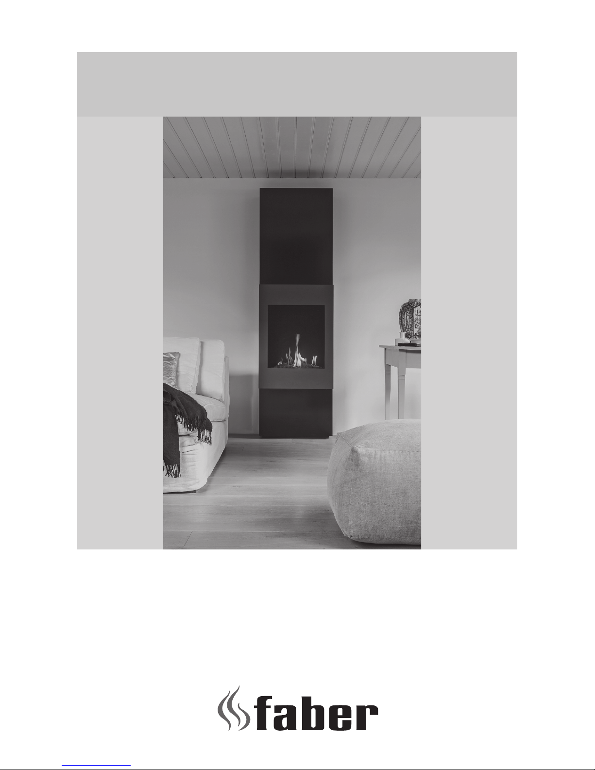
4.3 Preparingthere
• Remove frame (g 1.1 and 1.2)and glass and take the
packaged parts from the re.
• Store frame and glass in a safe place.
• Prepare the gas connection on the regulator
4.4 Positioningthere
Take the installation requirements into account (see Chapter 3).
• Put and level the re on the right place and mount it at the
wall with 4 screws. (Fig. 1.3)
• There are no levelling feet underneath the re.
4.5 Installingtheuematerials
• When penetrating a wall the opening must be at least 5mm
larger than the diameter of the discharge material.
See Chapter 13 for the height of this hole.
• Horizontal sections should be installed with a slope towards
the re (3 degrees).
• Build the system from the re. (Fig. 1.4). The telescopic part
ensures an easy installation.
> Please note:
The telescopic part must be xed with a self-tapping screw.
• The wall terminal can be cut.
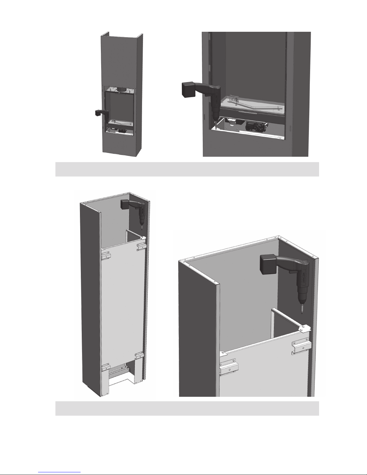
4.6 Positioning of the casing
If possible, carry out a performance test as described in chapter 7
on the re before placing the casing., (g. 1.5).
Put the casing on the supports left and right and screw it according
to g. 1.1 en 1.2.
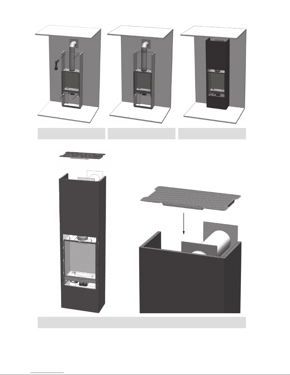
4.7 Positioning the cover plate
Put the cover plate on top of the casing. (See g. 1.6).
4.8 Placing the glass frame
Put the 4 brackets of the glass frame in the slotted holes of the
casing and lower the glass frame. (See g. 1.7).
Prevent damaging of the casing!
Removing the glass frame goes in reverse order.
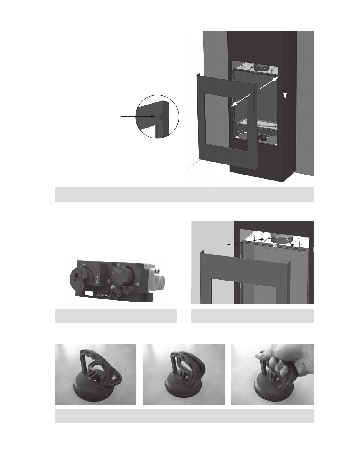
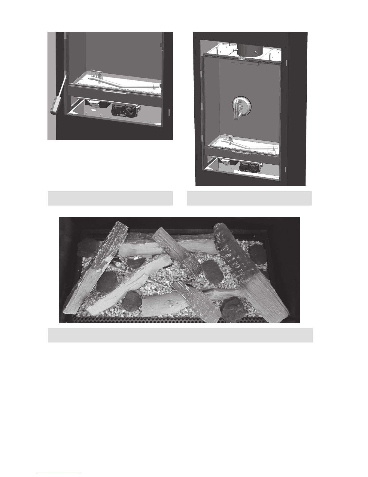
5 Removing the glass
• Remove the glass frame. (See par. 4.8)
• Place the suction cup onto the glass. (Fig. 3.1 and 3.3)
• Remove the glass clamps by using a screw driver.(Fig. 3.2)
• Move the glass forwards.
To replace the glass repeat the process in reverse order.
> Note:
Remove the ngerprints from the glass these will burn in and
cannot be removed after the re is used.
6 Placing the decoration material
It is not permitted to use other or to add more material in the
combustion chamber.
Keep the pilot light always free of decoration material!
Do not place all decoration material at one time on the burner; the
fabric parts can block it.
6.1 Log set
• Spread the vermiculate preferably by hand over the tube
burners. The surface of the pebbles may be very slightly
elevated from the burner plate but it should be level
throughout the entire length.
• Place the logs as specied. (see Fig. 4.1 or included log set
card)
• It is optional whether you apply chips to the combustion
chamber or not. Prevent chips from covering the burner, this
has a negative effect on the re image.
Start the re as described in the user manual. Check if the ame
distribution is good. Move the logs a little if necessary, until a good
ame distribution is achieved.
7 Checking the installation
7.1 Checking the ignition of the main burner and the
pilotame
Ignite the re as described in the user manual.
• Check that the pilot ame is well above the main burner and
not covered by chips.
• Check the ignition of the main burner on full and small
setting. (ignition must be smooth and quiet).
7.2 Checking for gas leaks
Check with a gas leak nder or spray all connections and pipes for
gas leakage.
7.3 Checking the burner pressure and primary
pressure
Check that the burner pressure and primary pressure match the
information listed in the manual, Chapter 11 Technical specicati-
ons.
Page 8

Installation Instructions
8
Measuring the primary pressure:
• Close the shutoff valve.
• Turn measuring nipple B (see Fig. 2.1) some turns open and
connect a measuring hose to the gas regulator.
• Take this measurement at highest setting of the re and when
the re is set to pilot light.
• Do not connect the unit if the pressure is too high.
Measuring the burner pressure:
Check the burner pressure only with
proper primary pressure.
• Turn measuring nipple A (see Fig. 2.1) some turns open and
connect a measuring hose to the gas regulator.
• The pressure must correspond to the value indicated in the
technical specications of this manual. In case of deviation
contact the manufacturer.
> Please note:
Close all pressure measuring nipples and
check for gas leakage.
7.4 Checkingtheameimage
Let the re burn for at least 20 minutes at highest setting and check
the ame for:
1. Flame distribution
2. Colour of the ames
If one or both points are not acceptable then check:
• The log set layout and/or the amount of chips on the burner.
• The pipe connections for leaks (in case of blue ames).
• Whether the correct Restrictor is tted.
• The outlet.
- Wall terminal right side up.
7.5 Flue gas analyzer
If you are in possession of a CO/CO2 ue gas analyzer, then it is
possible to check the supply air and the combustion gases.
There are two measuring pipes at the front of the re behind the
frame (Fig. 2.2) 1= air supply, 2 = ue gas.
The ratio CO2 and CO must not be greater than 1:100
Example:
CO2 is 4% and CO is 400ppm, measured at the highest point
If the ratio is greater than 1:100 or exhaust gases are measured in
the supply air, then also check above points.
8 Instructions for client
• Recommend that the unit should be checked annually by a
qualied specialist to ensure the safe use and to guarantee a
long service life.
• Give advice and instructions on care and cleaning of the
glass. Highlight the danger of burnt-in ngerprints.
• Instruct the customer on the operation of the unit and the
remote control, including replacing the batteries and setting
the receiver.
• Handover to customer:
- Installation instructions
- User manual
- Log set instruction card
- Suction Cups
9 Annual maintenance
9.1 Checking and cleaning:
• Check and clean if necessary after verication:
- The pilot light
- The combustion chamber
- The glass
- The logs for breakage.
- The outlet.
• Replace, if necessary:
- Vermiculite grains/chips
9.2 Cleaning the glass
Most deposits can be removed with a dry cloth. Clean the glass
with a ceramic hob cleaner.
> Please note:
Avoid ngerprints on the glass. These cannot be removed after
they are burnt in!
Now carry out check-up as described in Chapter 7 “Checking after
installation”.
10 Conversion to other gas type
The conversion to a different gas type may only be performed by a
qualied installer/dealer.
10.1 Conversion from natural gas to propane
(or vice versa)
This can only be done by replacing the burner. To do so, please
contact your dealer.
Specify with your order always the type and serial number of the
device.
Page 9

Installation Instructions
9
11 Technical data
II2H3+ II2H3+ II2H3+
Type appliance C11/C31/C91 C11/C31/C91 C11/C31/C91
Reference gas G20 G30 G31
Input Hi kW 4,5 4,5 4,5
Efficiency class 2 2 2
NOx-class 5 5 5
Inlet pressure mbar 20 30 37
Gas rate m³/h 0,482 0,127 0,164
(at 15º C and 1013 mbar) gr/h - 320 310
Burner pressure at full mark mbar 10 24,8 31,6
Injector main burner mm 1,9 1,1 1,1
Reduced input restraint mm 1,1 0,85 0,85
Pilot flame OP-NG9030 OP-LPG9222 OP-LPG9222
Code pilot flame injector - - -
Diameter outlet/inlet mm 100/150 100/150 100/150
Gas controle valve GV60 GV60 GV60
Gas connection 3/8" 3/8" 3/8"
Electrical connection V 230 230 230
Batteries receiver V (4x) 1,5 AA (4x) 1,5 AA (4x) 1,5 AA
Batteries remote V 9 9 9
Gas category
Page 10

Installation Instructions
10
Location Position outlet Distance mm
D Under a gutter 500
E Under a roof edge 500
F Under a carport or balcony 500
G Vertical downpipe 300
H Inside and outside corners 500
J From wall surface to a wall outlet 1000
K Two gable outlets against over each other 1000
L Distance between two roof outlets 450
M Two roof outlets above each other on a pitched roof 1000
N Two gable outlets next to each other 1000
Short roof terminal.
Only for existing
Chimney connection
Extension pipe over roof
12 Terminal position
> Please note:
> These rules apply only for the proper functioning of the unit,
for ventilation and environmental protection you need to
comply with the applicable rules as dened in the building
regulations.
Page 11

Installation Instructions
11
13 Support list
NO
YES
NONONO
YES
NO
YES
NO
- Learn a new code for remote.
- Battery remote.
- Battery receiver.
- Faulty adapter.
- Faulty receiver.
Light the pilot flame with
the remote, beep every
second?
No beep
Low battery
receiver.
- See inst. manual.
- 1x 9V Alkaline.
- 4x 1.5V AA Alkaline.
- Replace 6V adapter.
- Replace the receiver.
Clearly audible click
from the solenoid in
the gas valve?
- HT lead and sparking plug.
- Check the distance between
sparking plug and pilot top?
- Insulate the HT lead.
- Cut of a small piece from the
sparking plug.
- Tie-wraps removed?
- Cable is free from any metal parts?
4x 1.5V AA Alkaline
- Thermocouple circuit is
interrupted, check:
- 8 wire cable from receiver
to the gas valve.
- If the wire on the bottom
of the gas valve is not
broken or stuck and makes
a ground contact.
- Motor gas valve doesn't
work.
- Micro switch on gas valve
doesn't work.
3 short
beep's
1 long
beep
Faulty solenoid gas valve.
Replace the gas
valve.
Replace faulty
parts.
Every second a spark?
Check:
Pilot lights?
- Check power supply of the receiver.
- Air in the gas tube.
- Clean the pilot burner, primary air opening, flexible gas tube
and pilot injector.
- Check inlet pressure?
- Faulty solenoid?
(Clearly audible click from the solenoid in the gas valve)
Page 12

12
Installation Instructions
YES
NO
NO NO
YESNOYES
NO
NO
NO
NO
YES
NO
Pilot lift, thermocouple not
in pilot flame anymore.
Pilot stays lit
- Short circuit in the
thermocouple circuit.
- Faulty solenoid.
- Check the complete
wiring of thermocouple
circuit.
- Replace the gas valve.
Main burner starts
automatically?
- Knob A must be in the
ON position.
- Inlet pressure still ok?
Main burner
stays on?
Solenoid drops out while
motor is turning and gives 3
beep signals.
- Gasket between pilot burner is
leaking?
- Gasket between burner unit is
leaking?
- Glass seal is leaking?
- Flue parts aren't 100%
connected? (check flue system)
Replace batteries in the receiver.
Check the distance from
thermocouple to pilot flame?
Measure the mvolts over the
thermocouple, required min.
4mvolts over black and ground
contact.
Flame stays blue, lift from
the burner and fire switch
of?
- Check flue calculation.
(horizontal length to long?)
- Correct flue restrictor?
- Flue parts not correct installed?
- Wall/roof terminal blocked?
The flames are yellow
after 10/15 minutes?
Second thermocouple
(if present) isn't heated by
a flame from the
mainburner.
- Faulty second thermocouple (if present?)
- Check mvolts!
Min 1.2 mVolt
Min. 4 mV
Page 13

13
Installation Instructions
YES
NO
YES
NO
YES, the fire works OK
Fire can be switched
off with the remote?
- Check complete wiring
about thermocouple circuit.
- Replace faulty parts.
- RESET the receiver.
- Gas vlave broken, poor or
loose contact.
- Short circuit in wiring.
- Install a ground cable from
the gas valve to the
appliance.
Optional:
Step burner function can
be turned ON and OFF.
(only with remote)
- RESET the receiver
- Check the wiring from
solenoid valve to receiver.
- Faulty solenoid valve.
- Faulty receiver.
- Repaire the wiring.
- Replace solenoid valve.
- Replace receiver.
Page 14

14
Installation Instructions
14 Dimensional drawings
14.1 Concept I-450
Page 15

15
Installation Instructions
14.2 Position gasvalve and wall terminal
Page 16

16
www.faber.nl info@faber.nl
Saturnus 8 NL - 8448 CC Heerenveen
Postbus 219 NL - 8440 AE Heerenveen
Dealerinfo:
 Loading...