

Page 1
INSTRUCTIONS MANUAL
EN
COCKTAIL
Page 2
EN
3
3
RECOMMENDATIONS AND SUGGESTIONS
The Instructions for Use apply to several versions of this appliance. Accordingly, you may
find descriptions of individual features that do not apply to your specific appliance.
INSTALLATION
• The manufacturer will not be held liable for any damages resulting from incorrect or improper installation.
• The minimum safety distance between the cooker top and the extractor hood is 650 mm
(some models can be installed at a lower height, please refer to the paragraphs on working dimensions and installation).
• Check that the mains voltage corresponds to that indicated on the rating plate fixed to the
inside of the hood.
• For Class I appliances, check that the domestic power supply guarantees adequate
earthing.
Connect the extractor to the exhaust flue through a pipe of minimum diameter 120 mm.
The route of the flue must be as short as possible.
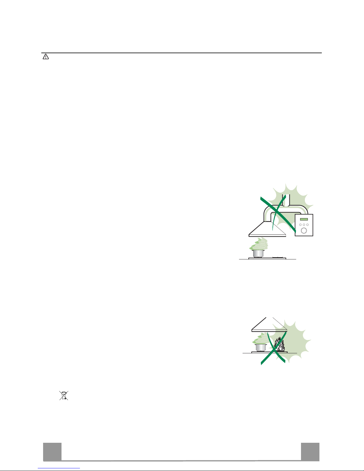
• Do not connect the extractor hood to exhaust ducts carrying combustion fumes (boilers,
fireplaces, etc.).
• If the extractor is used in conjunction with non-electrical appliances (e.g. gas burning appliances), a sufficient degree of aeration must be guaranteed in the room in order to prevent
the backflow of exhaust gas. The kitchen must have an opening communicating directly
with the open air in order to guarantee the entry of clean air. When the cooker hood is
used in conjunction with appliances supplied with energy other than electric, the negative
pressure in the room must not exceed 0,04 mbar to prevent fumes being drawn back into
the room by the cooker hood.
• In the event of damage to the power cable, it must be replaced by the manufacturer or by
the technical service department, in order to prevent any risks.
USE
• The extractor hood has been designed exclusively for domestic use to eliminate kitchen
smells.
• Never use the hood for purposes other than for which it has been designed.
• Never leave high naked flames under the hood when it is in operation.
• Adjust the flame intensity to direct it onto the bottom of the pan only, making sure that it
does not engulf the sides.
• Deep fat fryers must be continuously monitored during use: overheated oil can burst into
flames.
• Do not flambè under the range hood; risk of fire
• This appliance is not intended for use by persons (including children) with reduced physical, sensory or mental capabilities, or lack of experience and knowledge, unless they have
been given supervision or instruction concerning use of the appliance by a person responsible for their safety.
• Children should be supervised to ensure that they do not play with the appliance.
• “ CAUTION: Accessible parts may become hot when used with cooking appliances.”.
MAINTENANCE
• Switch off or unplug the appliance from the mains supply before carrying out any maintenance work.
• Clean and/or replace the Filters after the specified time period (Fire hazard).
• Clean the hood using a damp cloth and a neutral liquid detergent.
The symbol on the product or on its packaging indicates that this product may not be treated as household waste. Instead it shall be
handed over to the applicable collection point for the recycling of electrical and electronic equipment. By ensuring this product is disposed of
correctly, you will help prevent potential negative consequences for the environment and human health, which could otherwise be caused by
inappropriate waste handling of this product. For more detailed information about recycling of this product, please contact your local city office, your
household waste disposal service or the shop where you purchased the product
.
Page 3

EN
4
4
CHARACTERISTICS
Components
Ref. Q.ty Product Components
1 1 Hood Body, complete with: Controls, Light, Blower,
Filters
2.1 1 Upper Section (optional)
2.2 1 Lower Section (optional)
8 1 Directional Air Outlet grille
9 1 Flange (optional)
15 1 Angle iron (optional)
16 1 Filter cover
Ref. Q.ty Installation Components
7.2.1 2 Upper Chimney Section Fixing Brackets (optional)
11 6 Wall Plugs ( 4 optional )
11a 2 Wall Plugs SB 12/10
12a 6 Screws 4,2 x 44,4 ( 4 optional )
12c 10 Screws 2,9 x 6,5 ( 6 optional )
12d 6 Screws 2,9 x 9,5 ( 4 optional )
Q.ty Documentation
1 Instruction Manual
12d
2.1
2.2
12c
9
15
12a
7.2.1 11
1
12a
16
12c
12d
8
11
11a
Page 4
EN
5
5
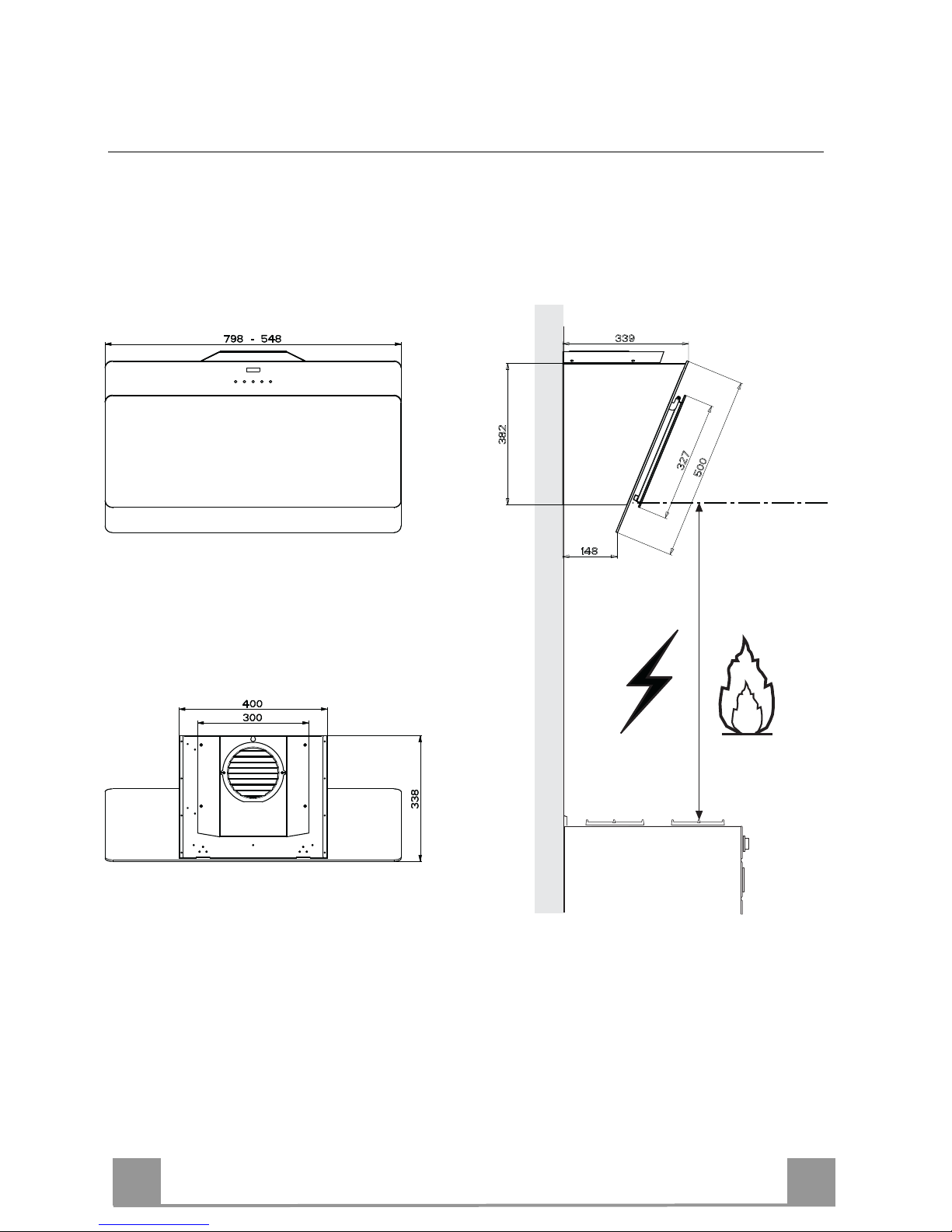
Dimensions
Min.
500mm
Min.
500mm
Page 5

EN
6
6
INSTALLATION
Wall drilling and bracket fixing
11a
1
1
22
140
11
12a
164 164
788
540
450
140
X
1÷2
7.2.1
As a first step, proceed with the following drawings:
• a vertical line up to the ceiling or up to the upper limit, at the centre of the area in which the
hood is to be fitted;
• a horizontal line at a minimum 788 mm above the cooker top.
• Mark a point (1) on the horizontal line, 164 mm to the right of the vertical reference line.
• Repeat this operation on the other side, checking that the two marks are levelled.
• Mark a reference point (2) as indicated at 140 mm from the vertical reference line and 540
mm above the cooker top.
• Repeat this operation on the other side, checking that the two marks are levelled.
• Drill at the marked points (1), using a ø 12 mm drill bit.
• Drill at the marked points (2) using a ø 8 mm drill bit.
• Insert the bracket plugs 11a into the holes (1) and tighten the screws.
• Insert plug 11 into holes (2).
To install a decorative chimney ( optional )
• Place bracket 7.2.1 on the wall, about 1-2 mm from the ceiling or from the upper limit,
aligning the centre (notch) with the vertical reference line.
• Mark the wall at the centres of the bracket holes.
• Place the bracket 7.2.1 on the wall at X mm below the first bracket (X = height of the upper
chimney section), aligning the centre (notch) with the vertical line.
• Mark the wall at the centres of the bracket holes.
• Drill ø 8 mm holes at all the marked centre points.
• Insert the wall plugs 11 in the holes.
• Fix the brackets using the 12a screws (4,2 x 44,4) supplied with the hood.
Page 6

EN
7
7
Fitting the hood body
• Open the doors/the door (See section Open Panels).
• Remove the Metal grease filters using the handles
provided.
• Adjust the two screws Vr, in the brackets 11a, so that
they are at the start of their travel.
• Hook the hood body to the two brackets 11a.
• From the inside of the hood body, turn screws Vr to
level the hood body itself.
• Fasten the safety screw 12a.
• Close the doors/the door again.
12a
Vr
11a
Connections
DUCTED VERSION AIR EXHAUST SYSTEM
When installing the ducted version, connect the hood to
the chimney using either a flexible or rigid pipe ø 150
or 120 mm, the choice of which is left to the installer.
• To install a ø 120 mm air exhaust connection, insert
the reducer flange 9 on the hood body outlet.
• Fix the pipe in position using sufficient pipe clamps
(not supplied).
• Remove possible charcoal filters.
ø 150
9
ø 120
Page 7

EN
8
8
RECIRCULATION VERSION AIR OUTLET
To install the Recirculation Version of the hood, the optional Activated charcoal cartridge kit must be purchased.
• Screw the filter cover onto the air outlet, using four screws 12c
(2.9 x 12.5).
• Fix the directional grille 8 on the recirculation air outlet using
the 2 screws 12d (2,9 x 9,5) provided.
16
12c
12d
8
ELECTRICAL CONNECTION
• Connect the hood to the mains through a two-pole switch having a contact gap of at least 3 mm.
• Remove the grease filters (see paragraph Maintenance) being
sure that the connector of the feeding cable is correctly inserted
in the socket placed on the side of the fan.
Flue assembly
The chimney can only be installed with exhausting hood
• Fasten the angle iron 15 to the hood canopy using the screws
12d (2,9 x 9,5) provided.
Upper exhaust flue
• Slightly widen the two sides of the upper flue and hook them
behind the brackets 7.2.1, making sure that they are well
seated.
• Secure the sides to the brackets using the 4 screws 12c (2,9 x
6,5) supplied.
Lower exhaust flue
• Slightly widen the two sides of the flue and hook them between the upper flue and the wall, making sure that they are
well seated.
• Fix the lower part laterally to the hood body using the 2 screws
12c (2,9 x 6,5) supplied.
12c
2.1
2.2
2
7.2.1
12c
Page 8

EN
9
9
USE
Control panel
T1 T2 T3 T4 L
Button Function
T1
Turns the Motor off. -
T2
Turns the motor on at speed one Buttons T1+T2 are on.
T3
Turns the Motor on at speed two Buttons T1+T3 are on.
Press and hold for 2 seconds to enable shutdown with a 30 minute delay (Motor+Lights). It is possible to change the operating speed when this function is enabled.
The respective buttons T1+
(T2 or T3 or T4) will flash.
T4
Turns the Motor on at speed three Buttons T1+T4 are on.
Press and hold for 2 seconds to activate Intensive speed, which is timed to run for 10
minutes. At the end of this time it will
automatically return to the speed set before.
Suitable to deal with maximum levels of
cooking fumes.
The button flashes.
L
Turns the Lighting System on and off at
maximum intensity.
Button on
Press and hold for 2 seconds to turn the
Lighting system on and off at reduced intensity.
Button on
Page 9

EN
1
10
MAINTENANCE
Opening Panel
• Open the Panel by pulling it.
• The panel can be locked in any position.
• Clean the outside with a damp cloth and neutral detergent.
• Clean the inside using a damp cloth and neutral detergent; do
not use wet cloths or sponges, or jets of water; do not use
abrasive substances.
Grease filters
CLEANING METAL SELF- SUPPORTING GREASE FILTERS
• The filters must be cleaned every 2 months of operation, or
more frequently for particularly heavy usage, and can be
washed in a dishwasher.
• Pull the comfort panels to open them.
• Remove the filters one by one pushing them towards the back
side of the hood unit and simultaneously pulling downwards.
• Any kind of bending of the filters has to be avoided when
washing them. Before fitting them again into the hood make
sure that they are completely dry. (The colour of the filter surface may change throughout the time but this has no influence
to the filter efficiency).
• When fitting the filters into the hood pay attention that they are
mounted in correct position the handle facing outwards.
• Close the comfort panel.
Page 10

EN
1
11
Activated charcoal filter (Recirculation version)
These filters are not washable and cannot be regenerated, and
must be replaced approximately every 4 months of operation, or
more frequently with heavy usage.
REPLACING THE ACTIVATED CHARCOAL FILTER
• Open the comfort panels pulling them downwards.
• Remove the metal grease filters
• Remove the saturated activated charcoal filter as shown (A).
• Fit the new filters (B).
• Replace the metal grease filters.
• Close the comfort panels.
A
B
Lighting
LIGHT REPLACEMENT
20 W halogen light.
• Remove the snap-on lamp cover by levering it from under the
metal ring, supporting it with one hand.
• Remove the halogen lamp from the lamp holder by pulling
gently.
• Replace the lamp with a new one of the same type, making
sure that you insert the two pins properly into the housings on
the lamp holder.
• Replace the snap-on lamp cover.
Page 11

FR
1
12
CONSEILS ET SUGGESTIONS
La présente notice d'emploi vaut pour plusieurs versions de l'appareil. Elle peut contenir des descrip-
tions d'accessoires ne figurant pas dans votre appareil.
INSTALLATION
• Le fabricant décline toute responsabilité en cas de dommage dû à une installation non correcte ou
non conforme aux règles de l’art.
• La distance minimale de sécurité entre le plan de cuisson et la hotte doit être de 650 mm au moins
(certains modèles peuvent être installés à une hauteur inférieure : se reporter aux paragraphes
« Encombrement » et « Installation »).
• Vérifier que la tension du secteur correspond à la valeur qui figure sur la plaquette apposée à
l’intérieur de la hotte.
• Pour les Appareils appartenant à la Ière Classe, veiller à ce que la mise à la terre de l’installation
électrique domestique ait été effectuée conformément aux normes en vigueur.
• Connecter la hotte à la sortie d’air aspiré à l’aide d’une tuyauterie d’un diamètre égal ou supérieur à
120 mm. Le parcours de la tuyauterie doit être le plus court possible.
• Ne pas connecter la hotte à des conduites d’évacuation de fumées issues d’une combustion tel que
(Chaudière, cheminée, etc…).
• Si vous utilisez des appareils qui ne fonctionnent pas à l’électricité dans la pièce ou est installée la
hotte (par exemple: des appareils fonctionnant au gaz), vous devez prévoir une aération
suffisante du milieu. Si la cuisine en est dépourvue, pratiquez une ouverture qui communique
avec l’extérieur pour garantir l’infiltration de l’air pur. Pour un emploi correct et sans risque, la
dépression maximum dans la pièce ne doit pas dépasser 0,04 mbar.
• En cas d’endommagement du cordon d’alimentation, faites-le remplacer par le constructeur ou par le
service après-vente, afin de prévenir tout risque.
UTILISATION
• La hotte a été conçue exclusivement pour l’usage domestique, dans le but d’éliminer les odeurs de la
cuisine.
• Ne jamais utiliser abusivement la hotte.
• Ne pas laisser les flammes libres à forte intensité quand la hotte est en service.
• Toujours régler les flammes de manière à éviter toute sortie latérale de ces dernières par rapport au
fond des marmites.
• Contrôler les friteuses lors de l’utilisation car l’huile surchauffée pourrait s’enflammer.
• Ne pas préparer d’aliments flambés sous la hotte de cuisine : risque d’incendie
• Cet appareil ne doit pas être utilisé par des personnes (y compris les enfants) ayant des capacités
psychiques, sensorielles ou mentales réduites, ni par des personnes n’ayant pas l’expérience et la
connaissance de ce type d’appareils, à moins d'être sous le contrôle et la formation de personnes
responsables de leur sécurité.
• Les enfants doivent être surveillés pour s'assurer qu'ils ne jouent pas avec l'appareil.
• « ATTENTION : Les parties accessibles peuvent devenir très chaudes si utilisées avec des appareils
de cuisson. »
ENTRETIEN
• Avant de procéder à toute opération d’entretien, débrancher la hotte en retirant la fiche ou en actionnant l’interrupteur général.
• Effectuer un entretien scrupuleux et en temps dû des Filtres, à la cadence conseillée (Risque
d’incendie).
• Pour le nettoyage des surfaces de la hotte, il suffit d’utiliser un chiffon humide et détersif liquide neutre.
Le symbole sur le produit ou son emballage indique que ce produit ne peut être traité comme déchet
ménager. Il doit plutôt être remis au point de ramassage concerné, se chargeant du recyclage du matériel
électrique et électronique. En vous assurant que ce produit est éliminé correctement, vous favorisez la prévention des conséquences négatives pour l’environnement et la santé humaine qui, sinon, seraient le résultat
d’un traitement inapproprié des déchets de ce produit. Pour obtenir plus de détails sur le recyclage de ce
produit, veuillez prendre contact avec le bureau municipal de votre région, votre service d’élimination des
déchets ménagers ou le magasin où vous avez acheté le produit.
Page 12

SRB
Novi Beograde: 011/ 31 33 598; 011/ 31 33 597; 011/ 31 33 264; 011/ 31 33 826
Bul. Arsenija čarnojevića 66
BEOLEKS
MK
Скопиjе: 02/ 322 75 80, ул. Народен Фронт Б-2, Кавадарци: 043/ 412 551, ул. Шишка Б.Б,
Битола: 047/ 242 885, ул. Прилепска 56, Тетово: 044/ 337 919, ул. Илинденска Б.Б
Струмица : 034 / 320 551, ул. Гоце Делчев бр.65
SKOLEKS
София: 02/963 33 20, 963 33 80, ж.к. Сухата Река бл. 49, Пловдив: тел.: 032/633 778, ул. Цар Асен 30,
Варна: тел.: 052/504 634, бул. Вл. Варненчик 277, Бургас: тел.: 056/841 475, ул. Фердинандова 77
Русе: тел.: 082/872 717, ул. Борисова 84, Плевен: тел.: 064/833 172,ул. Данаил Попов 4,
Велико Търново: тел.: 062/603 883,бул. България 26, Благоевград: тел.: 073/832 782, к-с Парангалица,
Видин: тел.: 094/600 209, ул. Цар Александър II, к-с Съединение, бл. 12
BGLEKS GROUP
 Loading...