

Faber Bright Installation Manual
Bright
K
40010660-0811
Installation Guide
IRL U
UK IRL
General
1.1 1.2
1.3
1 < < < <
UK IRL
C
1.4
A
D
1.5 1.6
B
> > > > 2
UK IRL
Bright
Build-in frame
2.1 2.2
3 < < < <
2.3 2.4
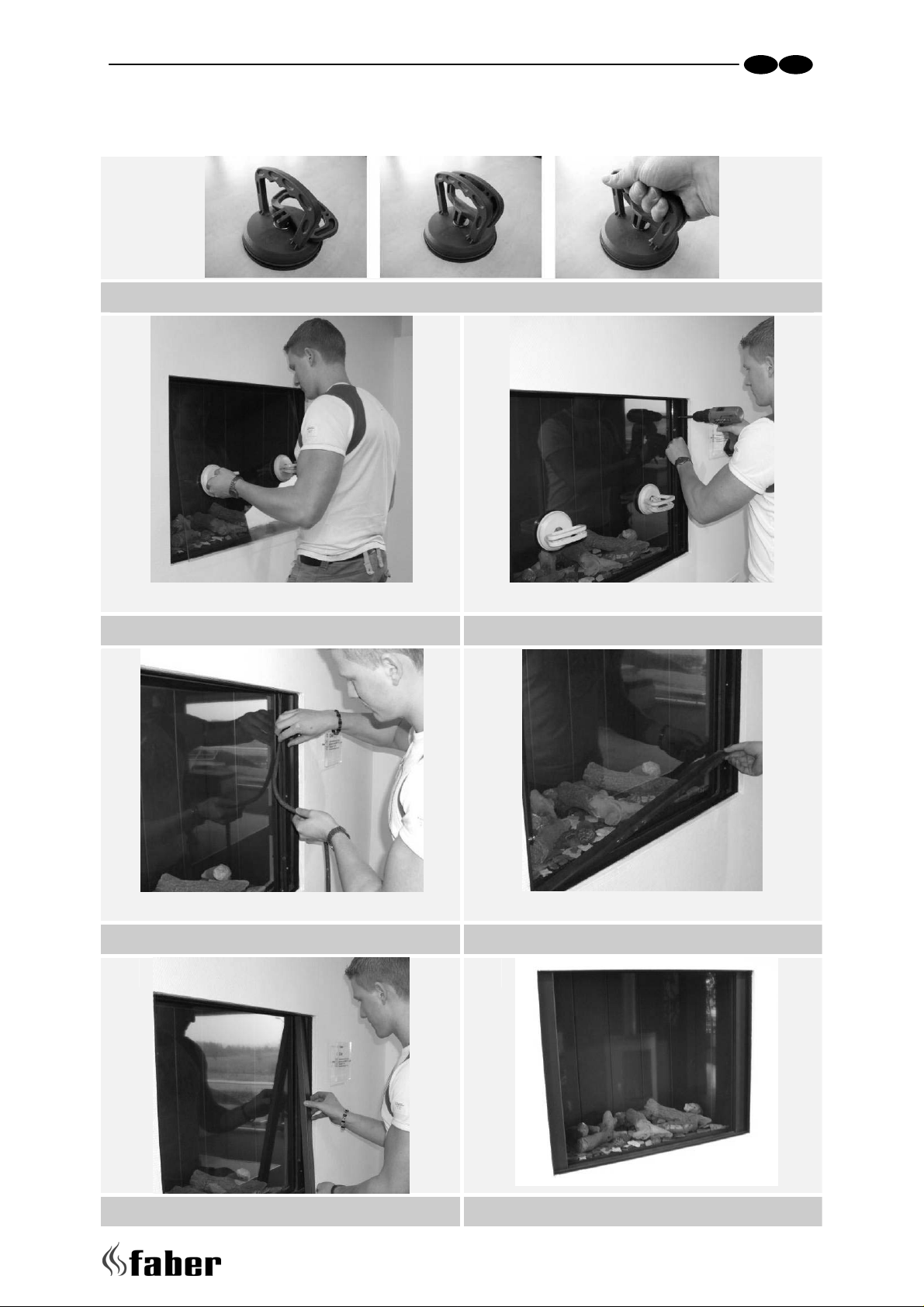
(De)mounting the Glass
3.1
UK IRL
3.2 3.3
3.4 3.5
3.6 3.7
> > > > 4

UK IRL
Content
1 Introduction ......................................................................................... 6
2 Safety and general information .................................................................. 7
3 Installation requirements ......................................................................... 8
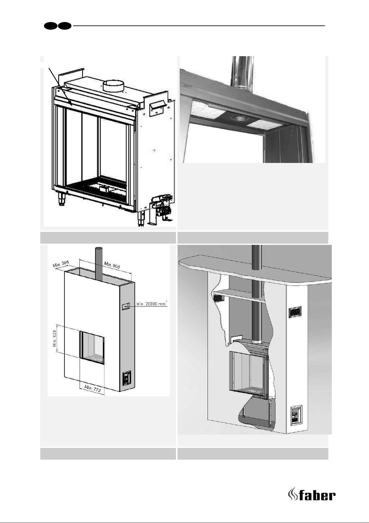
3.1 False chimney breast ........................................................................ 8
3.2 Flue requirements............................................................................ 9
3.3 Flue restrictor ................................................................................ 9
3.4 Terminal position ............................................................................ 9
3.5 Using an existing chimney. ................................................................10
4 Instruction for Installation .......................................................................11
4.1 Gas Connection..............................................................................11
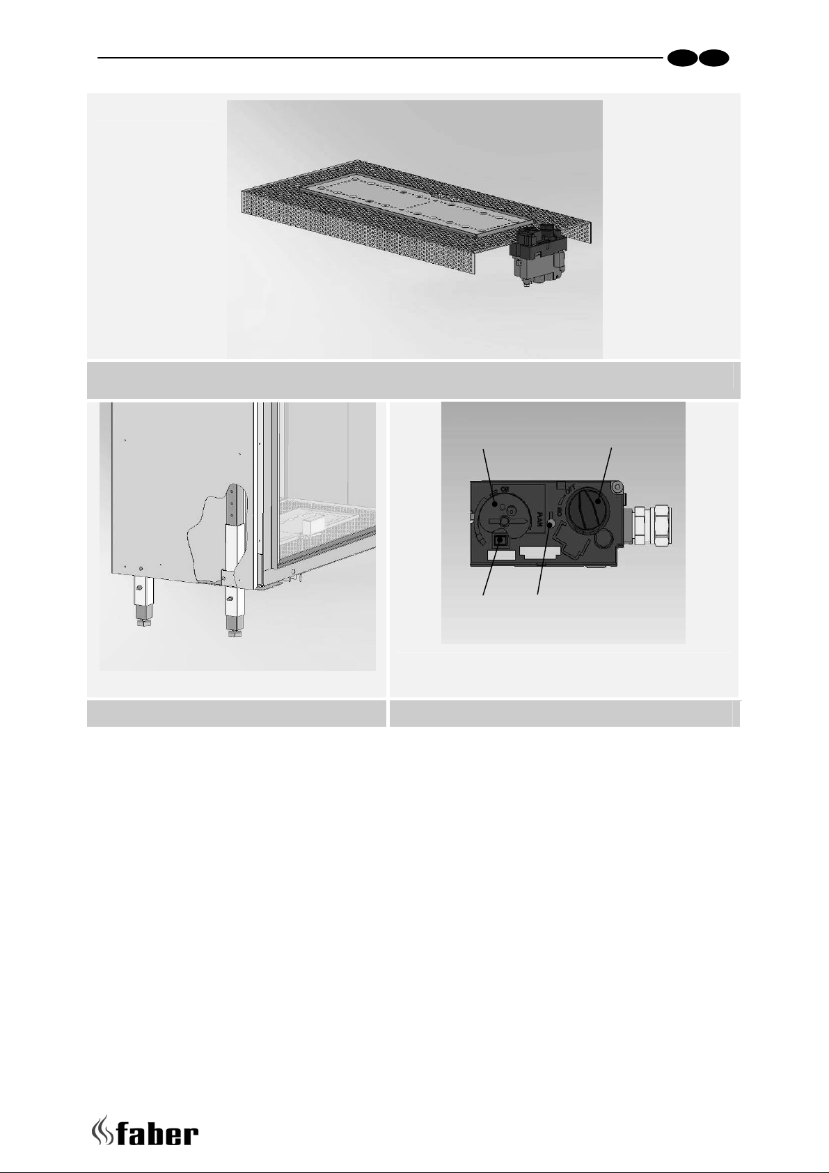
4.2 Preparing the appliance.................................................................... 11
4.3 Placing the appliance.......................................................................11
4.4 False chimney Breast....................................................................... 11
4.5 Building the False Chimney Breast. ......................................................12
4.6 Service hatch ................................................................................12
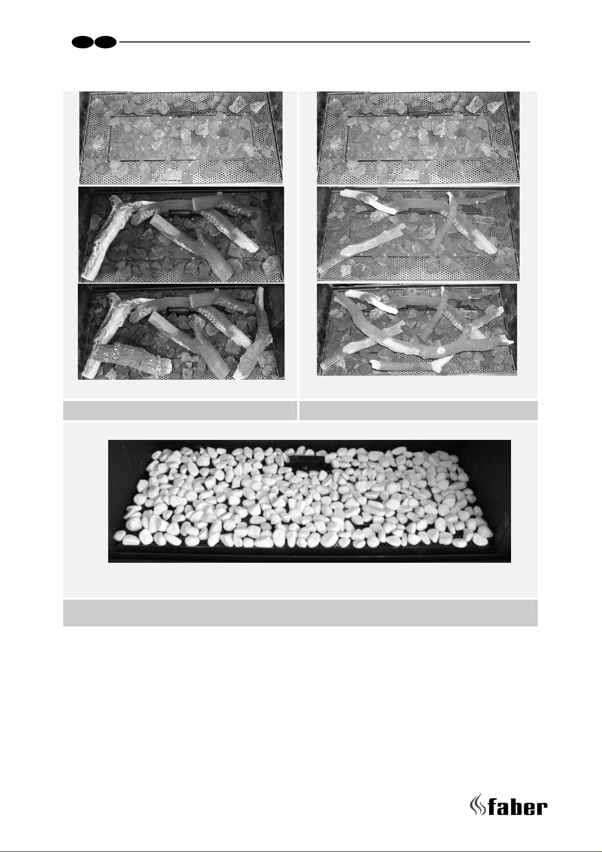
4.7 Placing the Log/Twig set or pebbles.....................................................12
4.8 Placing the glass............................................................................. 12
4.9 Removing the glass..........................................................................12
5 Commissioning (functional checks) .............................................................13
5.1 Pilot ignition check .........................................................................13
5.2 Check functional burner and pilot burner...............................................13
6 Handing over (final check and customer briefing) ...........................................14
7 Servicing ............................................................................................14
7.1 Routine annual servicing...................................................................14
7.2 Cleaning the glass...........................................................................14
7.3 Cleaning the combustion chamber and burner.........................................15
Appendix A: Example calculation..................................................................... 16
Appendix B: Flue restrictor............................................................................17
Appendix C: Installation of the flue..................................................................18
Appendix D: Technical specifications Flatburner ..................................................19
Appendix E: Dimensions Bright........................................................................ 20
Appendix F: Dimensions Convection grid............................................................21
Appendix G: Dimensions Service hatch .............................................................. 22
5 < < < <

UK IRL
1 Introduction
Note: these instructions should be read carefully and retained for future reference. Please
leave these instructions with the user.
• The Bright can be build on all desired heights
• The Bright is only in a frameless configuration available.
Special features:
• Room sealed appliance, inlet and outlet are led to the outside using a natural draught
concentric pipe system (100 mm/150 mm) (no power fan required)
• Air supply and flue-gases go to outside atmosphere through wall or roof. A horizontal
extension is possible (see appendix A and B).
• Remote Control is standard.
• Meets the requirements of the European Gas Appliance Directive (GAD) and carries
the CE mark.
> > > > 6

UK IRL
2 Safety and general information
Before installation, ensure that the local distribution conditions (identification of the type of
gas and pressure) and the adjustment of the appliance are compatible.
This gas appliance is factory set and can not be adjusted.
This appliance does not contain any component manufactured from asbestos or any asbestos
related products.
Ventilation
This appliance is room-sealed and doesn't require purpose provided ventilation.
Never use the appliance if it has a broken glass.
General safety
It is the law in the UK that all gas appliances, are installed by a competent person in
accordance with the Gas Safety (Installation and Use) Regulations (as amended), the
relevant British Standards for Installation work, Building Regulations, Codes of Practice and
the manufacturers instructions.
Always use an additional guard if there are elderly, infirm or children in the same room of
the appliance.
The installation should also be carried out in accordance with the following where relevant:
• BS5871 Part1
• BS5440 Parts 1 & 2
• BS1251
• Building Regulations Document J (as applicable)
• Building Regulations and Standards issued as relevant by the Department of the
Environment or the Scottish Development Department
• In the Republic of Ireland installation should be carried out in accordance with IS813,
ICP3, IS327, Building Regulations, Codes of Practice, the manufacturers instructions
and all other regulations in force
Failure to comply with the above could leave the installer liable to prosecution and
invalidate the appliance warranty.
7 < < < <
 Loading...