

Page 1

20
ENGLISH
EC MACHINE DIRECTIVE COMPLIANCE DECLARATION
(DIRECTIVE 89/392 EEC, APPENDIX II, PART B)
Manufacturer: FAAC S.p.A.
Address: Via Benini, 1
40069 - Zola Predosa
BOLOGNA - ITALY
Hereby declares that: the 961 B-E automation system
•is intended to be incorporated into machinery, or to be assembled with other
machinery to constitute machinery in compliance with the requirements of
Directive 89/392 EEC, and subsequent amendments 91/368 EEC, 93/44 EEC
and 93/68 EEC;
•complies with the essential safety requirements in the following EEC Directives:
73/23 EEC and subsequent amendment 93/68 EEC.
89/336 EEC and subsequent amendments 92/31 EEC and 93/68 EEC.
and furthermore declares that unit must not be put into service until the
machinery into which it is incorporated or of which it is a component has
been identified and declared to be in conformity with the provisions of
Directive 89/392 EEC and subsequent amendments enacted by the national
implementing legislation.
Bologna, 1 January 1997
Managing
Director
A. Bassi
Page 2

21
ENGLISH
IMPORTANT NOTICE FOR THE INSTALLER
GENERAL SAFETY REGULATIONS
1) WARNING! FAAC strongly recommends to follow these instructions literally for the safety of persons. Improper
installation or misuse of the product will cause very serious damages to persons.
2) Packaging material (plastic, polystyrene etc.) is a potential hazard and must be kept out of reach of children.
3)
Read the instructions carefully before installing the product.
4) Keep these instructions for future reference.
5) This product has been designed and manufactured only for the use stated in this manual. Any other use not expressly
set forth will affect the reliability of the product and/or could be source of hazard.
6) FAAC S.p.A. cannot be held responsible for any damage caused by improper use or different from the use for which
the automation system is destined to.
7) Do not use this device in areas subject to explosion: the presence of flammable gas or fumes is a serious hazard.
8) Mechanical constructive elements must comply with CEN pr EN 12650-1 and CEN pr EN 12650-2 standards.
Countries outside the EC shall follow the regulations above besides their national normative references in order to offer
the utmost safety.
9) FAAC cannot be held responsible for failure to observe technical standards in the construction of gates and doors,
or for any deformation of the gates which may occur during use.
10) Before carrying out any operations, turn off the system’s main switch.
11) An omnipower switch shall be provided for the installation with an opening distance of the contacts of 3 mm or more.
Alternatively, use a 6A thermomagnetic breaker with multi-pole switching.
12) Ensure that there is a differential switch up-line of the electrical system, with a trip threshold of 0.03A.
13) Check that the earthing plant is in perfect condition and connect it to the metallic parts. Also earth the yellow/green
wire of the operator.
14) The automation is fitted with an anti-crush safety system that is a torque control device. In any case, further safety
devices shall be installed.
15) The safety devices (e.g. photocells, safety edges, etc.) protect areas wherethere is a mechanical movement hazard,
e.g. crushing, entrapment and cutting.
16) Each installation must be fitted with at least one warning plate suitably fixed to the gate, besides the safety devices
as per point 15. above.
17) FAAC cannot be held responsible regarding safety and correct functioning of the automation in the event that parts
other than FAAC original parts are used.
18) Use only FAAC original spare parts for maintenance operations.
19) Do not carry out any modifications to automation components.
20) The installer must supply all information regarding manual operation of the system in the event of an emergency and
provide the end-user with the leaflet attached to the product.
21) Keep out of persons when the product is in operation.
22) Keep out of reach of children the remote radio controls and any control devices. The automation could be operated
unintentionally.
23) The end-user must avoid any attempt to repair or adjust the automation personally. These operations must be carried
out exclusively by qualified personnel.
24) What is not explicitly stated in these instructions is not permitted.
Page 3

22
ENGLISH
Table 2: Technical specifications of 960MP Electronic Control
Unit + 961 B-E Programming unit
Power supply 230 Vac (+6 -10%) - 50 (60) Hz
Accessories power supply 24 Vdc / 500 mA max.
Electric lock power supply (N.O./N.C.) 24 Vdc / 0.5 A max.
Standard operating functions (switch) Open / Automatic / Manual
(Night)
Adjustable functions (trimmer) Opening speed - Closing speed
Pulling force - Pause time
Selectable functions (microswitches) Overclosing stroke
Standard/non-standard initialisation procedure
Push and Go - Function switch (pos. “0”)
Terminal strip outputs Door open/closed signal -
Malfunction alarm signal-
24 Vdc electric lock power supply
(N.O./N.C.) - 24 Vdc accessories power supply Presence signal (gong) - PC connection signals -
“Interlock” signals - “Double leaf door” signals
Terminal strip inputs Function switch/CODIS (optional) -
Internal / external / emergency /
STOP safety device / CLOSURE safety device
1.1 APPLICATION LIMITS
Important: To ensure correct application of the FAAC 961 B-E
unit the weight of the door must not exceed the value given in
Table 3 corresponding to its length.
The maximum length of the leaf is 1400 mm.
The values of maximum weight vary according to the driving
arm used.
For each driving arm there is also a different maximum value for
the depth of the doorpost (Table 4) beyond which it is not
possible to install the system correctly.
Table 3: Application limits of 961 B-E automatic unit
700 367 286 750 320 249 800 281 219 850 249 194 194
900 222 173 173
950 199 155 155
1000 180 140 140
1050 163 127 127
1100 149 116 116
1150 136 106 106
1200 125 97 97
1250 115 90 90
1300 107 83 83
1350 99 77 77
1400 92 71 71
Table 4: Max. depth of doorpost
mm
FAAC 961 B-E
The 961 B-E automatic unit for swing doors is a one-piece unit
consisting of an electromechanical device that allows door
opening to be controlled by means of a driving arm. The door
is re-closed by a spring system.
The operator can be installed either on the lintel or on the door
structure itself.
The stainless steel protective casing houses the electronic
control unit used to program and control the operation of the
system.
In the event of a power failure the door can be pushed (or
pulled) open manually.
1. DESCRIPTION AND TECHNICAL CHARACTERISTICS
Sliding arm
0 - 125 126 - 250 0 - 160 0 - 160
Pulling
articulated
arm
Pushing
articulated
arm (Var. 02)
Table 1: Technical specifications of 961 B-E Operator
Power supply 230 Vac (+6 -10%) - 50 (60) Hz
Absorbed power 100 W
Current drawn 0.5 A
Electric motor 24 Vdc with encoder
Dimensions 530 x 100 x 104 (length x height x depth)
Weight 10 kg
Ambient temperature -15 +70 °C
Housing protection IP 23
Dimensions and max. weight of leaf see Table 3 (section 1.1)
Duty cycle continuous
Operation in event of power failure Manual push/pull opening -
Spring closure
Configuration of driving arms • pushing articulated arm
(version for jamb depth 0-125 mm)
• pushing articulated arm - (version for jamb depth
126-250 mm) • pulling articulated arm • sliding arm
Anti-crushing device standard
Opening angle 70-95°
Opening time 3.5 - 10 s (adjustable)
Closing time 6 - 13 s (adjustable)
Max. weight of leaf
(kg)
Pulling articulated
arm
Max. weight of leaf
(kg)
Sliding arm
Pushing
articulated
arm (Var. 01)
3
1
2
6
7
13
12
11
10
9
8
5
4
a
Cable hole
b
Support profile
c
960 MP electronic control unit
d
Position monitoring microswitch
e
Spring loading adjustment screw
f
Transmission shaft
g
Drive system
h
DC motor
i
961 B-E programming unit
j
Closing spring
k
Protective casing
l
Operating function switch
m
End cover (2)
Fig. 1
Length of leaf
(mm)
Max. weight of leaf
(kg)
Pushing articulated
arm
Page 4

23
ENGLISH
2. ELECTRICAL SETUP (fig. 2a Standard system)
a
961 B-E operator
b
Microwave radar / Passive infrared sensor
c
T20E external key-switch (KEY command)
d
Emergency Closing/Opening pushbutton
e
CODIS programming unit (optional)
f
CODIS inhibition switch (optional)
g
24 Vdc electric lock
h
Junction box
If the operator is installed on the door, make the electrical
connections using a junction box and suitable commercially
available pipes/unions (fig. 2b).
N.B.: 1) For installation of electrical cables use suitable rigid
or flexible piping.
2) Always keep the low voltage accessory connection
cables separate from the 230 V power cables. Use
separate sheaths to avoid any interference.
3. INSTALLATION
3.1 PRELIMINARY CHECKS
To ensure correct operation of the automatic unit the structure
of the existing door must meet the following requirements:
-
length and weight as specified in Table 3 (section 1.1);
- max. doorpost depth as specified in Table 4;
- robust and rigid structure of the leaf;
- good condition of the existing hinges;
- smooth, uniform movement of the leaf with no abnormal
friction at any point of its travel;
-
“neutral” position of the door during its entire travel. If the door
tends to close or open, check the alignment of the hinges.
- Presence of mechanical end stops.
3.2 MOUNTING THE OPERATOR
1) Remove the protective casing (fig. 3) and the end covers
(fig. 4) from the operator.
Warning: Before removing the end cover with the function
switch, remove the connector joining the switch to the 960MP
electronic control unit.
2)
As regards the mounting position of the operator (on the
lintel or on the door) and the type of arm to use (pushing,
pulling or sliding), refer to the relevant mounting table and
drill the holes required to mount the operator and the
pulling arm.
N.B.: The two intermediate operator fixing holes are not in a
central position (see mounting tables). The holes are offset in
order to ensure that the operator is mounted with the correct
direction of rotation of the mechanism.
The mounting tables are the following:
Table A: LINTEL MOUNTING (PUSHING ARTICULATED ARM)
Outward opening
Table B: DOOR MOUNTING (PUSHING ARTICULATED ARM)
Inward opening
Table C: LINTEL MOUNTING (PULLING ARTICULATED ARM)
Inward opening
Table D: LINTEL MOUNTING (SLIDING ARM) Inward opening
3) Mount the operator using the six M6 screws and washers
provided.
Warning:
- The structure of the lintel (or the door) at the operator
mounting position must not exhibit any significant
deformation.
- The operator must be mounted parallel to the floor.
N.B.: If the sliding arm is to be used, the driving arm must be
mounted before the operator is fixed on the lintel (see section
3.3.3.).
3.3 MOUNTING THE DRIVING ARMS
3.3.1 MOUNTING THE PUSHING ARTICULATED ARM (fig. 5)
1) Close the door.
2) Free arms (1) and (2) by pulling apart the coupling (3)
manually as shown in fig. 5.
3) Fit arm (1) on the operator transmission shaft by means of
the extension and the screw (4) provided (fig. 5).
The arm
must be mounted perpendicular to the closed door.
N.B.:
If a greater distance between the operator and the arm
is required, use the higher extensions available as accessories
(see Table A/B).
4) Mount plate (5) of arm (2) on the door or the lintel using the
two M6 screws and the washers provided (fig. 5). The
installation distances are given in Table A/B.
5) Slacken the fixing screw (6) and assemble the two arms by
means of coupling (3) (fig. 5).
6) Turn arm (1) until arm (2) is perpendicular to the closed
door or the lintel as shown in fig. 5 (a-b), sliding the spacer
(7) along arm (2).
7) Tighten the fixing screw (6) between the two arms.
The length of arm (2) is given in the relevant mounting
tables. If necessary, cut off the section of the arm extending
beyond the articulation and then cover the ends using the
caps provided (fig. 5).
8) Check manually that the door is free to open and close
fully and that it comes to rest against the mechanical end
stops. If the door does not close correctly, adjust the return
spring as described in section 10.
Important: The two driving arms must never touch.
N.B.: For 90° opening it is not necessary to install the mechanical
opening stop (microswitch no. 2 in OFF position - see section 5).
3.3.2 MOUNTING THE PULLING ARTICULATED ARM (fig. 6)
1) Close the door.
2) Free arms (1) and (2) by pulling apart the coupling (3)
manually as shown in fig. 6.
3) Fit arm (1) on the operator transmission shaft by means of
the extension and the screw (5) provided (fig. 6).
The arm
must be mounted parallel to the closed door.
N.B.: If a greater distance between the operator and the arm
is required, use the higher extensions available as accessories
(see Table C).
4) Mount plate (6) of arm (4) on the door using the two M6
screws and the washers provided (fig. 6). The installation
distances are given in Table C.
5) Slacken the screws (7) and slide the attachment (8) along
arm (4) so as to position it at distance D given in Table C.
Having done this, tighten screws (7).
6) Slacken screw (9) and assemble the two arms using the
coupling (3) (fig. 6).
7) Turn arm (1) as shown in fig. 6(a) until it reaches a distance
of 83 mm from the lintel. Having done this, tighten the fixing
screw (9) between the two arms. If necessary, cut off the
section of the arm extending beyond the articulation and
then cover the ends using the caps provided (fig. 6).
8) Check manually that the door is free to open and close
fully and that it comes to rest against the mechanical end
stops. If the door does not close correctly, adjust the return
spring as described in section 10.
Important: The driving arms must never touch.
3.3.3 MOUNTING THE SLIDING ARM (fig. 7)
1) Mount arm (1) on the operator transmission shaft by means
of the extension and the screw (2) provided (fig. 7).
The
arm must be fitted pointing 45° outwards as shown in fig.
7(a).
N.B.: If a larger distance is required between the operator and
the arm use the higher extensions available as accessories
(see Table D).
Warning: Mount arm (1) on the transmission shaft before fitting
Page 5

24
ENGLISH
the operator on the lintel (fig. 7).
2) Insert the roller (3) inside the sliding guide (4) (fig. 7).
3) Pull arm (1) inwards manually as shown in fig. 7(b) and
secure the sliding guide (4) by means of two M6 screws on
the closed door as shown in Table D.
4) Check manually that the door is free to open and close
fully and comes to rest against the mechanical end stops.
If the door does not close correctly, adjust the return spring
as described in section 10.
4. START-UP
1) Make the electrical connections to the 960 MP electronic
control unit as described in section 6.
To gain access to the control unit, pass the cables through
the special conduit (fig. 1 - ref. 1) as shown in fig. 8.
2) Fit the two end covers and connect up the function switch.
The end cover with the switch may be fitted on the right or
the left. For cable routing refer to fig. 8.
3) Turn the operating function switch (fig. 1 - ref. 12) to
position I (AUTOMATIC logic).
4) Check that the programming unit microswitches (fig. 10)
are all in the OFF position.
Important:
When mounting the “pulling articulated” or “sliding”
arms or for opening angles greater than 90°, turn microswitch
no. 2 to ON before connecting power to the system.
5) Close the door.
6) Power up the operator. Powering is signalled by an acoustic
signal from a buzzer.
7) Check that the 5V LED on the programming unit (fig. 9)
lights up.
8) At the end of the initialisation procedure, check the status
of the signalling LEDs on the programming unit as shown in
Table 5.
Table 5: Operation of status LEDs
LED ON OFF
5 V logic powered logic not powered
OK command active command inactive
YES safety devices active safety devices inactive
N.B.: The status of the LEDs with the door closed at rest is shown
in bold type.
4.1. INITIALISATION PROCEDURE
As soon as the system is powered up, it runs an initialisation
procedure which includes setting the following parameters:
- measuring the mass of the door;
- determining the end stop positions;
- determining the point at which the STOP safety device
intervenes (see section 6).
The door opens at low speed, then closes half way before
switching back to opening.
Subsequent closure is performed by the return spring.
The initialisation procedure is indicated by an intermittent
acoustic signal (frequency 1 sec) emitted by a buzzer on the
programming unit (table 6).
The process may be inhibited due to:
- function switch in the 0 (MANUAL) position;
- incorrect connection of the accessories (electric lock,
control/safety devices);
- incorrect positioning of the programming unit microswitches.
N.B.: To repeat the initialisation procedure
hold down the RESET
button (fig. 11 - ref. 4) for more than 4 seconds.
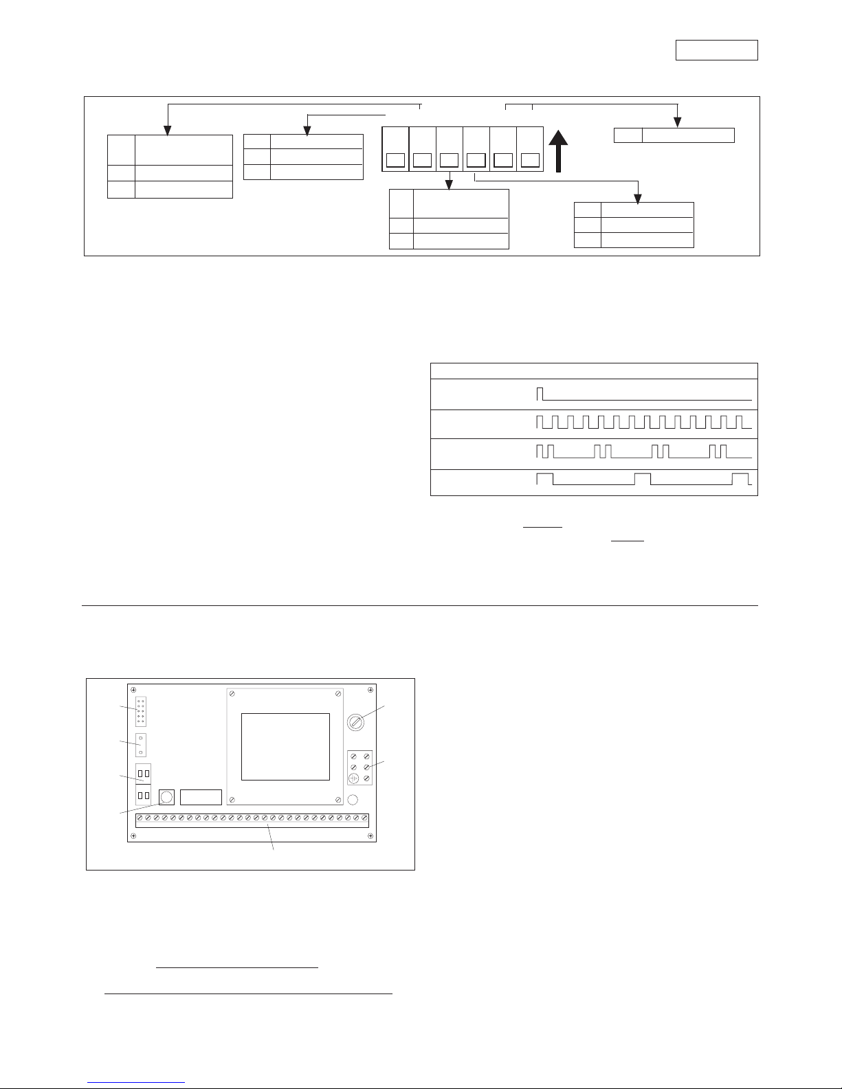
5. 961 B-E PROGRAMMING UNIT
5.1 LAYOUT AND DESCRIPTION
5.2. SETTING THE ADJUSTING TRIMMERS
The programming unit features trimmers (fig. 9 - ref. 3) which
regulate the following parameters:
Trimmer Vo to set the opening speed.
Setting 30 ÷ 100% of the initialisation value.
Standard setting 50%.
Trimmer Vc to set the closing speed.
Setting 30 ÷ 100% of the initialisation value.
Standard setting 50%.
N.B.: The speed initialisation values depend on the dimensions
and the mass of the door.
Trimmer To to set the pause time (AUTOMATIC logic).
Setting from 1 to 30 seconds.
Standard setting 3 seconds.
Trimmer Fm to set the pulling force of the operator.
Setting 60 ÷ 100% of maximum value.
Standard setting 100%.
Turn the trimmers clockwise to increase the values of the
settings.
Turn the trimmers anticlockwise to reduce the values of the
settings.
with 960 MP electronic control unit
f
Encoder
g
Connector (2 pole) for connection
with 960 MP electronic control unit
a
Signalling LEDs (see Table 5)
b
Signalling buzzer (see section 5.4.)
c
Adjusting trimmer
d
Programming microswitches
e
Connector (16 pole) for connection
123456
S1S2S3S4S5
S6
FmToVc
Vo
SIOK5V
43 2 1
7
65
Fig. 9
Page 6
25
ENGLISH
5.3. PROGRAMMING THE MICROSWITCHES (fig. 10)
S1 S2 S3 S4 S5 S6
S2
Initialisation
procedure
OFF Standard
ON Non-standard
S1
Overclosing stroke
OFF Inactive
ON Active
S3
Function switch
position “0”
OFF Manual
ON Night
S4
“Push and Go”
OFF Active
ON Inactive
S5-S6
Inactive
Fig. 10
ON
Suono
Pausa
1 s
4 s
8 s
6. 960 MP ELECTRONIC CONTROL UNIT
Warning: Always disconnect the electric power supply before
carrying out any work on the control unit (connection,
maintenance).
for the connection. The screening must be fixed underneath
the special screws (fig. 14 - ref. 1).
Important: The maximum permissible length of the
connection cable is 50 m.
To inhibit operation of the CODIS, interrupt the jumper
between terminals 3 and 4 and install a switch (fig. 14 - ref. 2).
Warning: If the CODIS is used on a continuous basis, function
no. 7 must be activated at level III (see section 8).
Activation of input 3 (fig. 14) enables the NIGHT or ONEWAY operating functions to be given priority over the
function selected on the CODIS unit. To select the priority
function, program the CODIS suitably at level III (function
no. 2 - see section 8.3). The input can be activated by
means of a timer.
4. Electric lock - Common
5. Electric lock - N.C. contact (max. capacity 0.5 A/24 V) (fig.
15). The output is suitable for commanding a magnetic
closure system. If no power is supplied, the electric lock is
not active. In the NIGHT function the electric lock is powered
and hence active. In the event of an opening command
(internal command or EMERGENCY OPENING), the power
supply to the electric lock is temporarily cut off to allow the
door to be opened.
6. Electric lock - N.O. contact (max. capacity 0.5 A/24 V) (fig.
16). If no power is supplied the electric lock is active and
therefore guarantees-CLOSING mechanical locking. In
the NIGHT function the electric lock is active even if no
power is supplied. In the event of an opening command
(internal command or EMERGENCY OPENING), the electric
lock is temporarily powered to enable the door to be
opened. In this case a reverse stroke command is also
5.4. SIGNALLING BUZZER
The programming unit incorporates a buzzer which emits
sequences of acoustic signals corresponding to different
statuses of the system. The statuses that have occurred and
their identification sequence can be seen in Table 6.
Table 6: Acoustic signals
STATUS SIGNALLED ACOUSTIC SEQUENCE
Connection to mains
power supply
Initialisation procedure
Alarm: Error "A"
Alarm: Error "B"
The indication of error A does not inhibit the operation of the
automation unit. The indication of
error B inhibits the operation
of the automation unit until the fault is eliminated.
Table 8 (paragraph 8.4) contains a list of the malfunction
conditions indicated by the system. To identify the fault, connect
the CODIS external programming unit (optional).
The programming unit has a series of microswitches which
allow the functions shown in fig. 10 to be selected.
The system is supplied with all the microswitches in the OFF
position.
5.3.1. OVERCLOSING STROKE
This function enables the closed position force to be increased
by further loading the transmission system after the door has
reached the mechanical closure end stop.
It is advisable to use this function if the door is subject to
pressure caused by atmospheric agents (e.g. gusts of wind)
when closed.
5.3.2. INITIALISATION PROCEDURE
If pulling articulated arms or sliding arms are mounted or in the
event of opening angles of more than 90°, the NON-STANDARD
process must be selected. In this case an external mechanical
stop must always be provided.
5.3.3. FUNCTION SWITCH (“0” POSITION)
This function allows the operating function to be selected with
the switch in the “0” position (see section 7).
5.3.4. PUSH AND GO
When activated, this function enables the opening command
to be given by pushing the closed door manually. It is sufficient
to give the door an initial push in the opening direction.
a Fuse F1 1AT/230Vac - 5x20
b Terminal strip X1 (230 V) - fig. 12
c Low voltage terminal strip X2 / X4
Description of the terminal strip
1. - 2. - 3.
Connection of function switch (fig. 1 - ref. 12) as
shown in fig. 13.
Connection of CODIS programming unit (optional) as
shown in fig. 14.
Use a 2 x 0.5 mm2 screened cable (bus communication)
Sound
Pause
N.B.: Press RESET after every programming operation.
1 2 3 4 5 6 7 8 9 10 11 12 13 14 15 16 171819 20 21 22 23 24 25 26 27 28
X6
X5
X7
X2 X4
X1
F1
7
6
5
4
3
1
2
Fig. 11
Page 7

26
ENGLISH
Fig. 17
Fig. 16
Fig. 15
Fig. 19/a
Fig. 18
N.F. N.O.
C
–+
INTERNAL SENSOR
N.F. N.O.
C
–+
EXTERNAL CONNECTOR
BROWN
WHITE
GREEN
YELLOW
GREY
(not connected)
+24 Vdc
0 Vdc
INTERNAL COMMAND
EXTERNAL COMMAND
GREY
(not connected)
78910
BROWN
WHITE
GREEN
YELLOW
Fig. 23
Fig. 22
Fig. 21Fig. 20
Fig. 19/b
Fig. 14
COM.
17 18 19
DOOR
OPEN
DOOR
CLOSED
max 0.5A/24 Vdc
78 13
+ 24 Vdc
0 Vdc
CL. SAFETY
BROWN
WHITE
GREEN
TX
RX
MINISWITCH
BROWN
WHITE
N.C.
contacts
11 12 13 14 15 16
EMERGENCY CLOSURE
(OPENING)
STOP SAFETY
CLOSURE SAFETY
+24 Vdc
0 Vdc
0 Vdc
INTERNAL
COMMAND
0 Vdc
8910
EXTERNAL
COMMAND
0
12
230 V (+6 -10%)
50 (60) Hz
123
white
brown
green
0 Vdc
L = screened cable 2 x 0.5 mm 2; 50 m max.
2
NIGHT
(ONE-WAY)
CODIS
L
L
1 23
2
1
4
3
0 Vdc
1
1
45678
EL. LOCK N.C.
EL LOCK N.O.
+24 Vdc
0 Vdc
< 0,5A
max. 0,5A/24 Vdc
EL. LOCK COM.
45678
+24 Vdc
0 Vdc
max. 0,5A/24 Vdc
< 0,5A
EL. LOCK N.C.
EL LOCK N.O.
EL. LOCK COM.
26 27 28
TXD
RXD
0 Vdc
RS 232
Fig. 13
Fig. 12
KEY
DOUBLE LEAF
DOOR SIGNAL
GONG/INTERLOCK
SIGNAL
0 Vdc
22 23 24 25
TERM. 14
300mA
maxi
20 21
COM.
20 21
ALARM
max. 0.5 A/24 Vdc
Page 8

27
ENGLISH
1
0
2
given to enable the mechanical release of the system.
7. Accessories power supply (+24 Vdc)
8. Accessories power supply (0 Vdc)
9. Internal command: any control device (pushbutton,
photocell, sensor, etc.) which, by closing a contact, can
command an opening cycle of the system from inside.
10. External command: any control device (pushbutton,
photocell, sensor, etc.) which, by closing a contact, can
command an opening cycle of the system from outside.
Fig. 17 shows the control device connection. To install
more than one internal/external control device, connect
the N.O. contacts in parallel.
Connecting microwave radar / passive infrared sensors.
In the conventional configurations the control units are
microwave radar and/or passive infrared sensors. To
connect the FAAC sensors/radar units equipped with a 5pole electrical cable, refer to fig. 18.
11. Emergency control (fig. 19/a): any control device (normally
a pushbutton) which, by opening a contact, commands
an emergency closure of the system. Alternatively this
input can be used to command emergency opening by
programming the system in a suitable manner using the
CODIS programming unit (optional).
To install more than one emergency control device,
connect the N.C. contacts in series.
N.B.: If emergency control devices are not connected,
jumper inputs 11 and 15.
Activating function no. 6 at CODIS programming level III
enables the emergency control to be activated by closing
a N.O. contact.
In this case, in order to install more than one emergency
control device, connect the N.O. contacts in parallel.
12. STOP safety control (fig. 19/a): any device (safety sensor,
photocell, etc.) which, by opening a contact, has a safety
effect on the operating cycle. In particular, this safety
device interrupts the opening/closing movement of the
door.
When the safety device is disengaged, the door resumes
its opening/closing movement and continues to the end
of the cycle.
To install more than one STOP safety device, connect the
N.C. contacts in series.
N.B.: If STOP safety devices are not installed, jumper inputs
12 and 15.
13. CLOSURE safety command (fig. 19/a): any device (safety
sensor, photocell, etc.) which, by opening a contact, has
a safety function on the closing movement of the door.
The safety device causes an immediate reversal of the
closing movement of the door, but has no effect on the
opening movement of the door.
To install more than one CLOSURE safety device, connect
the N.C. contacts in series.
N.B.: If CLOSURE safety devices are not connected, jumper
inputs 13 and 15.
Connection of MINISWITCH photocells
The MINISWITCH photocells can be used as a safety device.
POSITION “1”: AUTOMATIC
When an internal/external command is given, the door opens and then re-closes after the pause time.
POSITION “0”: MANUAL/NIGHT
The position “0” can be used to select two different operating functions according to the programming carried out on the 961
B-E programming unit (see section 5.3.3).
The two functions are:
MANUAL: The door can be opened manually. The return spring pulls the door closed again.
NIGHT: The external command is inactive. The door can be opened solely by
activating the internal command (fig. 22) or EMERGENCY OPENING (fig. 19/a) input.
POSITION “2”: OPEN
When this function is selected, the door opens and remains open. The door can be closed only by activating the EMERGENCY
CLOSURE input (fig.19/a).
Fig. 24
For connection, see figure 19/b.
14. Accessories power supply (+24 Vdc)
15. - 16. Accessories power supply (0 Vdc)
17. Status signal output: Common (fig. 20)
18. Door open signal output (max. contact capacity 0.5 A / 24
Vdc) (fig. 20)
19. Door closed signal output (max. contact capacity 0.5 A /
24 Vdc) (fig. 20).
Terminals 17/18 and 17/19 can be used to power two 24
Vdc (max. 0.5 A) warning lamps to provide door open and
door closed signals respectively (fig. 20).
20. - 21. Alarm signal output (max. contact capacity 0.5 A / 24
Vdc).
Terminals 20 and 21 can be used to power a 24 Vdc (max.
0.5 A) warning lamp for remote signalling of an alarm
condition (fig. 21).
The operator signals a malfunction by means of an acoustic
alarm from a buzzer (see Table 6).
22. “KEY” opening command (fig. 22): any device which, by
closing a contact for more than 3 seconds, commands
door opening in any operating function selected.
To install more than one “KEY” command, connect the
N.O. contacts in parallel.
23. Output for “DOUBLE LEAF” application (fig. 22): see section
9.2
24. Output for GONG acoustic signal / Output for “INTERLOCK”
application (fig. 22):
When the CLOSURE safety device comes into operation, it
activates the output between terminals 14 and 24 for one
second at intervals of 0.5 seconds. The output is suitable for
controlling an acoustic signal (GONG). The maximum load
is 300 mA (fig. 22).
In the event of “INTERLOCK” operation, it is necessary to
activate function no. 3 at CODIS level III and use outputs 24
and 25 for the connection between the two operators
(see section 9.1).
25. 0 Vdc
26. - 27. - 28. PC connection: These outputs allow for interfacing
with a PC, which if necessary can control a number of
doors from a single central unit (fig. 23).
For this application refer to the relevant technical manual.
d RESET button
N.B.: To RESET, hold down the button for at least 4 seconds.
e Position monitoring microswitch connector (fig. 1 - ref. 4).
f Programming unit connector (2 pole)
g Programming unit connector (14 pole)
7. FUNCTION SWITCH
The 961 B-E operator has a 3-position function switch (0-1-2)
mounted on one of the end covers (fig. 1 - ref. 12). This cover
can be fitted on the right or the left as required (fig. 8).
The switch electrical connection is shown in fig. 13.
The selectable operating functions are shown in fig. 24.
Page 9

28
ENGLISH
8.2. LEVEL II - ADJUSTABLE FUNCTIONS
Important: Level II is active only if the CODIS is used permanently
(function 7 of Level III activated). The CODIS programming unit
has one adjusting level.
Six parameters can be set. They are displayed on the righthand side of the CODIS front panel, with the relevant LEDs:
RESET LED 6 o RESET: repeat initialisation process
(see paragraph 4.1).
LED 5 o OPENING SPEED: adjust to 30 ÷ 100%
of initialisation value.
The standard setting is 100%.
LED 4 o CLOSING SPEED: adjust to 30 ÷ 66%
of initialisation value.
The standard setting is 66%.
LED 3 o OPENING EXCURSION: adjust
maximum opening by 60 to 100%.
The standard setting is 100%.
LED 2 o PAUSE TIME: adjust to 0-30 seconds.
The opening is controlled by means
of the activation of the internal/
external control devices.
The standard setting is 2 seconds.
LED 1 o NIGHT PAUSE TIME: adjust to 0-30
seconds. The opening is controlled
by means of the activation of the
KEY/EMERGENCY OPENING
commands.
The standard setting is 7 seconds.
8.2.1. ADJUSTMENT OF PARAMETERS
To access Level II (adjustable functions), proceed as follows:
1) Select the parameter to be adjusted by causing the
relevant LED to light up. Press the “+” pushbutton to move
the lighting of the LEDs one position up. Press the “-”
pushbutton to move the lighting of the LEDs one position
down.
2) Press the “+” and “-” pushbuttons simultaneously.
The LED relevant to the selected parameter will start flashing
in order to give information about the stored value: if the
flashing rate is high, a high door speed or a short pause
time has been stored; if the flashing rate is low, a low door
speed or a long pause time has been stored.
3) Press the “+” or “-” pushbutton repeatedly, in order to
increase or decrease the flashing frequency of the LED,
that is to say, to change the value of the selected
parameter. When the “+” pushbutton is pressed, the door
speed, opening excursion and pause time are increased.
Fig. 25
8. “CODIS” EXTERNAL PROGRAMMING UNIT (OPTIONAL)
The 961 B-E automation unit can also be controlled by an
external programming unit in place of the function selector
and of the 961 B-E programming unit.
The CODIS (see figure 25) has four levels of operation, where
the user can select the operating functions and set, programme
and monitor the operation of the system.
If the CODIS is used permanently, it is necessary to activate
function 7 at Level III (programming functions): see paragraph
8.3.
For the electrical connection of the CODIS, consult figure 14.
The operation of the CODIS can be inhibited in the two
following ways:
- by cutting the jumper between terminals 3 and 4 by means
of a switch (fig. 14);
- by activating function 9 at Level III; in this case it is possible
to operate the unit temporarily after having entered code
“+ + - - + +” by means of the “+” and “-” pushbuttons.
After 2 minutes the CODIS will stop again automatically.
Note: the CODIS can also be used as a temporary programming
unit. In this case, Level II (adjustable functions) is inactive.
When the programming of the system has been completed,
the CODIS can be removed: all the programmed functions will
remain unaltered.
After having removed the CODIS, perform a RESET or switch off
the system.
8.1 LEVEL I - OPERATING FUNCTIONS
This is the level that is accessible to the user. By pressing either
the “+” or the “-” pushbutton, the user can select the operating
function.
Five operating functions are available. They are displayed on
the left-hand side of the front panel of the CODIS.
When a function has been selected, the corresponding LED
lights up on the front panel.
Press the “+” pushbutton to move the lighting of the LEDs one
position up.
Press the “-” pushbutton to move the lighting of the LEDs one
position down.
The five available functions displayed on the panel are:
o LED 6 MANUAL
The door is released and can be
operated manually.
The control devices are inactive.
o LED 5 OPEN
The door opens and remains open.
o LED 4 AUTOMATIC
The door opens when internal or
external commands are active and
re-closes after the pause time.
o LED 3 AUTOMATIC (SPARE)
o LED 2 ONE-WAY
Entry (or exit) inhibited; only one
direction of exit (or entry); opening
when internal (or external) command
is active; closing after pause time.
The external (or internal) control
devices are inactive.
o LED 1 NIGHT
The door is locked shut by the electric
lock.
The external command is inactive.
The door can be opened solely by
activating the internal command or
EMERGENCY OPENING input. The
door closes after the night pause
time.
LEDS DI SEGNALAZIONE
FUNZIONI
REGOLABILI
PULSANTI DI COMANDO
FUNZIONI
OPERATIVE
®
ERROR
Tpn
Tp
P
Vc
Vo
RESET
6
5
4
3
2
1
STATUS LEDS
ADJUSTABLE
FUNCTIONS
OPERATING
FUNCTIONS
PUSHBUTTON
CONTROLS
Vo
Vc
P
Tp
Tpn
Page 10
29
ENGLISH
FUNCT.NO.
LEDS FUNCTIONS LED 6
12345
0 OFF OFF OFF OFF OFF Output Level III OFF
1 ON OFF OFF OFF OFF One-way with lock active OFF
One-way with lock inactive ON
2 OFF ON OFF OFF OFF NIGHT function (terminal 3-960MP) OFF
ONE-WAY function (terminal ON
3-960MP)
3 ON ON OFF OFF OFF Gong output (terminal 24-960MP) OFF
Interlock output (terminal 24-960MP) ON
4 OFF OFF ON OFF OFF SLAVE (interlock) OFF
MASTER (interlock) ON
5 ON OFF ON OFF OFF Emergency closing (terminal OFF
11-960MP)
Emergency opening (terminal ON
11-960MP)
6 OFF ON ON OFF OFF Emergency command - N.C. OFF
contact (terminal 11-960MP)
Emergency command - N.O. ON
contact (terminal 11-960MP)
7 ON ON ON OFF OFF CODIS - temporary connection OFF
CODIS - permanent installation ON
8 OFF OFF OFF ON OFF 15 kg static force OFF
9 kg static force ON
9 ON OFF OFF ON OFF CODIS inhibited inactive OFF
CODIS inhibited active ON
10 OFF ON OFF ON OFF Standard opening pause time OFF
Immediate closing ON
11 ON ON OFF ON OFF Door open/closed indication - N.O. OFF
contact (terminals 18/19-960MP)
Door open/closed indication - N.C. ON
contact (terminals 18/19-960MP)
12 OFF OFF ON ON OFF Alarm warning - N.O. OFF
contact (terminal 21-960MP)
Alarm warning - N.C. ON
contact (terminal 21-960MP)
13 ON OFF ON ON OFF “Double swing door” output inactive OFF
“Double swing door” output ON
active (terminal 23-960MP)
14 OFF ON ON ON OFF SLAVE (double swing door) OFF
MASTER (double swing door) ON
15 ON ON ON ON OFF Restore STANDARD settings OFF
Retain programmed settings ON
16 OFF OFF OFF OFF ON Opening commands stored OFF
(interlock)
Opening commands not stored ON
(interlock)
17 ON OFF OFF OFF ON TEST programme inactive OFF
TEST programme active ON
18 OFF ON OFF OFF ON Level II RESET active OFF
Level II RESET inactive ON
19 ON ON OFF OFF ON STANDARD internal command OFF
(terminal 9-960MP)
STEP-BY-STEP internal command ON
(terminal 9-960MP)
When the “-” pushbutton is pressed, the door speed,
opening excursion and pause time are decreased.
4) Return to Level I (operating functions) by pressing the “+”
and “-” pushbuttons simultaneously.
Notes: - The CODIS automatically returns to Level I after 2
minutes of inactivity.
- To prevent the settings from returning to standard
values after a RESET or a voltage drop, “protect” the
programmed values by activating function 18 at
Level III (see paragraph 8.3).
8.3. LEVEL: III - PROGRAMMING FUNCTIONS
The CODIS has a programming level where certain functions
can be selected.
These functions are required for several special applications.
Note: a voltage drop or a RESET command will not cancel the
programming on Level III.
Standard programming can be restored by means of function
15 (see Table 7).
To access Level III, proceed as follows:
1) Select the NIGHT operating function by causing LED 1 to
light up. Press the “+” pushbutton to move the lighting of
the LEDs one position up. Press the “-” pushbutton to move
the lighting of the LEDs one position down.
2) Press the “+” and “-” pushbuttons simultaneously for about
2 seconds, until the red ERROR LED lights up.
3) Enter the access code by pressing the “+” and “-”
pushbuttons in the following sequence: “+ + + - - + + +”.
Note: after the lighting up of the red ERROR LED, if the code is
not entered within 10 seconds the CODIS will automatically
return to Level I.
4) .Select the function to be programmed by pressing the “+”
or “-” pushbutton so as to obtain the combination of lit LEDs
indicated in Table 7.
5) Press the “+” and “-” pushbuttons simultaneously to activate
or deactivate the function, and check the status of LED 6,
according to the indications of Table 7.
Note: the standard programming is the one with LED 6 unlit
(OFF).
6) To return to Level I (operating functions), repeatedly press
the “-” pushbutton until all the six LEDs are off, then press
the “+” and “-” pushbuttons simultaneously.
Note: the CODIS will automatically return to Level I after 2
minutes of inactivity.
8.3.1. AVAILABLE FUNCTIONS
function 1
One-way with lock activated: in the ONE-WAY operating
function, the closed door is locked by the electric lock.
One-way with lock deactivated: in the ONE-WAY operating
function, the closed door is not locked by the electric lock.
function 2
NIGHT function: the activation of the input between terminals
2 and 3 (960MP) selects the NIGHT operating function, with
priority over the function selected on the CODIS.
ONE-WAY function: the activation of the input between
terminals 2 and 3 (960MP) selects the ONE-WAY operating
function, with priority over the function selected on the CODIS.
The control panel will show which function has been selected,
by means of the lighting up of LED 1 or 2.
When the input is deactivated, the operating function
previously selected on the CODIS returns automatically.
function 3
Gong output: the operation of the closing safety device
activates the 24 Vdc output between terminals 14 and 24
(960MP) for 1 second, at intervals of 0.5 seconds.
Table 7: programming functions
Page 11

30
ENGLISH
Interlock output: between terminals 24 and 25 (960 MP) it is
possible to pick up the signal for the interlocking of the two
automation units (see paragraph 9.1).
function 4
SLAVE/MASTER: in the interlocking operation of the two
automation units, it is necessary to define which door is to
operate as MASTER (normally it is the inner one) and which
door is to operate as SLAVE.
function 5
Emergency closing: the activation of the input between
terminals 11 and 15 (960MP) controls the closing of the door no
matter which operating function has been selected.
Emergency opening: the activation of the input between
terminals 11 and 15 (960MP) controls the opening of the door
no matter which operating function has been selected.
function 6
Emergency command - N.C. contact: to activate the input
between terminals 11 and 15 (see function 5), an opening
pulse of a N.C. contact is required.
Emergency command - N.O. contact: to activate the input
between terminals 11 and 15 (see function 5), a closing pulse
of a N.O. contact is required.
function 7
CODIS - temporary connection: the CODIS can be used only
initially to activate certain functions. When the external
programming unit is removed, the function that has been
activated remains stored. In this case, Level II is inhibited, and
the settings (speed, pause times, etc.) must be performed by
means of the internal 961 B-E programming unit.
CODIS - permanent installation: the CODIS is installed
permanently; the four operating levels are all active.
function 8
15 kg static force / 9 kg static force: this function makes
it possible to change the sensitivity of the anti-crushing
device.
function 9
CODIS inhibited inactive / CODIS inhibited active: this function
makes it possible to activate the CODIS electronic inhibition. In
this condition, no programming can be performed at any
level.
To release the CODIS temporarily, press the “+” and “-”
pushbuttons in the following sequence: “+ + - - + +”.
This operation may be carried out for two purposes:
1) to change the operating function or modify some settings
at Level II; in this case, after 2 minutes the CODIS inhibition
will come again;
2) to remove the CODIS inhibition; in this case, it is necessary
to access Level III and to disable that function.
function 10
Standard opening pause time: the pause time begins with the
door open and the control devices (e.g., sensors) inactive.
Immediate closing: the door closes when the control devices
(e.g., sensors) are inactive. In this case, directional sensors must
be used.
function 11
Door open/closed indication - N.O. contact: the open and
closed positions of the door are indicated by the closing of an
N.O. contact (terminals 18/19-960MP).
Door open/closed indication - N.C. contact: the open and
closed positions of the door are indicated by the opening of a
N.C. contact (terminals 18/19-960MP).
function 12
Alarm warning - N.O. contact: the alarm condition is indicated
by the closing of a N.O. contact.
Alarm warning - N.C. contact: the alarm condition is indicated
by the opening of a N.C. contact.
function 13
“Double swing door” output inactive /active: between terminals
23 and 25 (960MP) it is possible to pick up the signal for the
operation of a double swing door (see paragraph 9.2).
function 14
SLAVE / MASTER: in the application for a double swing door, the
automation of the leaf whose opening is to be anticipated
must be programmed as MASTER, while the automation of the
leaf whose opening is to be delayed must be programmed as
SLAVE.
function 15
Restore STANDARD settings / Retain programmed functions:
this function makes it possible to check whether any function
has been programmed differently from the standard settings.
If at least one function has been programmed differently from
the standard settings, LED 6 is lit (ON).
In this case all the standard settings can be restored by
pressing the “+” and “-” pushbuttons simultaneously.
After this operation, it is advisable to perform a RESET.
function 16
Opening commands stored (interlock): in interlock operation,
it is not necessary to wait until one door has closed before
commanding the opening of the other.
Opening commands not stored (interlock): in interlock
operation, it is necessary to wait until one door has closed
before commanding the opening of the other.
Opening commands given during the operating cycle of the
first door will have no effect.
function 17
TEST programme inactive/active: this function makes it possible
to activate consecutive operating cycles. The control devices,
in any case, take priority over the operation of the system. The
programme can be cancelled by performing a RESET.
function 18
Level II RESET active / inactive: this function makes it possible to
preserve the settings of the opening, closing and opening
excursion speeds even in case of a voltage drop or RESET.
function 19
STANDARD internal command: the activation of the internal
control device controls a complete door cycle (standard
operation).
STEP-BY-STEP internal command: the activation of the internal
control device controls a sequence of door opening / stopping
/ closing / stopping / opening, and so on.
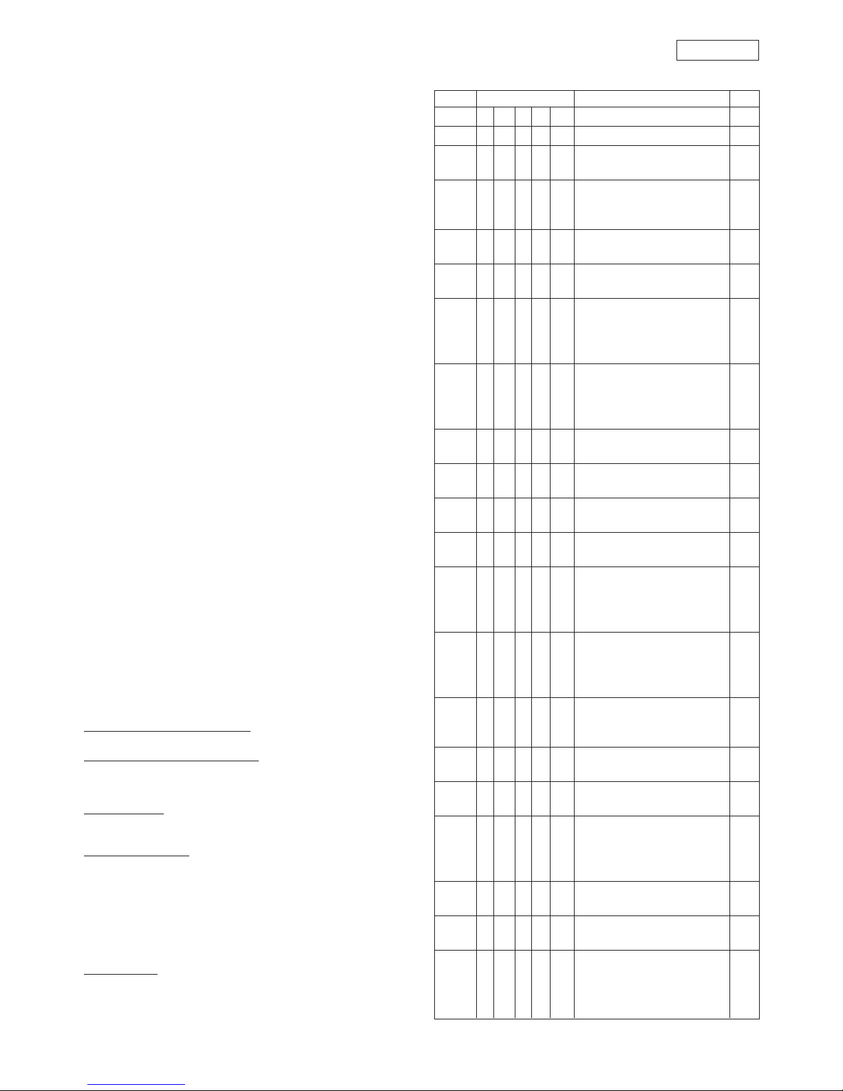
8.4. LEVEL IV - SELF-DIAGNOSIS
The CODIS programming unit has a self-diagnostic level, which,
in case of a fault, interrupts the display of the operating
function every 2 seconds in order to display the malfunction
condition for 0.5 seconds. The type of fault can be identified by
observing the combination of LEDs 1-5 that are lit together with
the red ERROR LED (see Table 8).
Page 12

31
ENGLISH
Table 8
NO. LEDS FAILURE NOTE
1 2 3 4 5 (*)
1 ON OFF OFF OFF OFF
Motor fault
B
2 OFF ON OFF OFF OFF
Governor and brake fault
B
3 ON ON OFF OFF OFF
Initialisation process not possible
B
Opening angle insufficient
4 OFF OFF ON OFF OFF
Initialisation process not possible
B
Opening angle excessive
5 ON OFF ON OFF OFF
Friction or spring load excessive
B
6 OFF ON ON OFF OFF
Spring load insufficient
B
7 ON ON ON OFF OFF
Motor overload
B
8 OFF OFF OFF ON OFF
Encoder fault (disconnected
B
or in short circuit)
9 ON OFF OFF ON OFF
Cut-off relay fault
B
10 OFF ON OFF ON OFF
EPROM / RAM / relay fault (automatic
B
control)
11 ON ON OFF ON OFF
Short circuit on 24 V (960MP electronic
B
control unit or external)
12 OFF OFF ON ON OFF
Monitoring microswitch fault
A
13 ON OFF ON ON OFF
Electric lock fault
B
14 ON ON ON ON OFF
Power supply insufficient
(< 140 V) B
15 OFF OFF OFF OFF ON
Microprocessor fault
B
16 ON OFF OFF OFF ON
Incorrect “door closed” position
A
17 OFF ON OFF OFF ON
Microprocessor alarm
B
18 ON ON OFF OFF ON
“Double swing door”
A
communication error
9. SPECIAL APPLICATIONS
9.1. INTERLOCK
The programmable interlock function makes it possible to
interlock the operation of two doors so that the opening of one
is dependent on the closing of the other and vice versa.
Electrical connections
• Connect the two automations to the same power supply
line.
• Connect the X2 terminal strips of the two 960MP electronic
control units to each other, as shown in Figure 26.
• Connect the control devices and the emergency
command, if present, as shown in figure 27.
The emergency command makes it possible for the two doors to
open or close simultaneously, depending on the programming
performed on the CODIS (see Table 7, function 5).
Note: the control devices must be connected only to the KEY
input (see figure 27).
Programming and selection of operating function
To enable the interlock operation, the appropriate
programming of the following Level III functions must be
performed (see paragraph 8.3):
• Function 3: select the Interlock output option on both the
CODIS programming units (LED 6 lights up).
• Function 4: select the MASTER option on the CODIS unit of
the inner door (LED 6 lights up); select the SLAVE option on
the CODIS unit of the outer door (LED 6 goes out).
• Function 16: select the desired option on both the CODIS
programming units.
IMPORTANT: the interlock operation is activated only if the
NIGHT or ONE-WAY operating function has been selected on
both the CODIS programming units (see paragraph 8.1).
9.2. DOUBLE SWING DOOR
The programmable “double swing door” function makes it
possible to synchronise the movement of the two leaves that
face each other (see figure 29). For a correct operation of the
system, the opening of one leaf must be anticipated and its
closing must be delayed.
Note: the difference between the opening angles of the two
leaves must not exceed 20°.
Electrical connections and programming
- Connect the X2 terminal strips of the two 960MP electronic
control units to each other, as shown in figure 28.
- Connect the internal and external control devices, the
emergency command, if present, and the electric lock to
the electronic control unit of the MASTER automation (see
fig. 29).
Note: the MASTER automation actuates the leaf whose opening
X2
24 25
X2
24 25
Fig. 27
Fig. 26
X2
CHIAVE
X2
11 12
OVAC
CHIAVE
CH;/D'EMERGENZA
15
22 25
N.O.
N.C. (N.O.)
N.C. (N.O.)
11 12
15 22 25
OVAC
CH;/D'EMERGENZA
N.O.
EMERGENCY CL./OP.
KEY
OVdc
N.C.
(N.O.)
EMERGENCY CL./OP.
KEY
OVdc
(*)A: this error condition does not inhibit the operation of the system.
B
: this error condition inhibits the operation of the automation unit until
the fault has been eliminated.
FUNCT.NO.
LEDS FUNCTIONS LED 6
12345
3 ON ON OFF OFF OFF Gong output (terminal 24-960MP) OFF
Interlock output (terminal 24-960MP) ON
4 OFF OFF O N OFF OFF SLAVE (interlock) OFF
MASTER (interlock) ON
16 OFF OFF OFF OFF ON Opening commands stored OFF
(interlock)
Opening commands not stored ON
(interlock)
If the Opening commands stored option has been selected
(LED 6 unlit), it is not necessary to wait for one of the doors to
close before controlling the opening of the other.
When the closing of the first door has been completed, the
second door opens automatically.
If the Opening commands not stored option has been selected
(LED 6 lit) it is necessary to wait for one of the doors to close
before controlling the opening of the other.
Opening commands given during the operating cycle of the
first door will have no effect.
Table 9 indicates the functions to be programmed.
Table 9
Page 13

32
ENGLISH
FUNCT.NO.
LEDS FUNCTIONS LED 6
12345
13 ON OFF ON ON OFF
“Double swing door” output
OFF
inactive
“Double swing door” output active ON
14 OFF ON ON ON OFF
SLAVE (double swing door)
OFF
MASTER (double swing door)
ON
Fig. 28
Fig. 29
tendre
détendre
Aperto
Chiuso
K
A (corretta) B (non corretta)
PORTA CHIUSA
PORTA APERTA
Open
Fig. 30
Fig. 31
SLAVE
MASTER
SLAVE
MASTER
B (incorrect)
A (correct)
DOOR CLOSED
DOOR OPEN
movement must be anticipated (and whose closing movement
must be delayed).
- Connect the safety devices on the 960MP electronic control
units of the MASTER and SLAVE automations.
- Connect the two automations to the same power supply
line.
-
On both the automations, activate function 13, “double
swing door” output (ON), then define which is the MASTER leaf
and which is the SLAVE one by programming function 14
(fig.29).
Table 10 indicates the functions to be programmed.
Table 10
10. MAINTENANCE
It is advisable to check the automation unit once a year, in
order to make sure that the dragging system and closing spring
are in perfect working order.
Drive system (fig. 1 - ref. 7)
Check the toothed wheels and, if necessary, lubricate them
with grease for gears or bearings TRIBOTECH VTP 473.
Important: never use spray lubricants.
Closing spring (fig. 1 - ref. 10)
With the door closed, draw a vertical line on the spring, as
shown in figure 30.
Open the door and check the state of the line: figure 30 shows
two possible configurations.
In case B (fig. 30), lubricate the spring coils with KLÜBER
MICROLUBE GBU Y 131 grease, with the door both open and
closed.
Adjustment of spring load
If the spring load is insufficient or excessive, proceed as follows:
1) Select the MANUAL function (function selector in position
“0”).
2) Release the arm fastened to the shaft from the second
transmission arm.
3) Keep the arm in position and remove the screw that
adjusts the spring load (fig. 1 - ref. 5).
4) Load or unload the spring by rotating the arm in the
appropriate direction, and insert the screw in positioning
bore K (fig. 31).
5) Restore the system and check its operation is correct.
6) Perform any adjustments that may be needed, and lock
the adjusting screw (fig. 1 - ref. 5) with Loctite.
Important: after the adjustment of the spring load, the system
travel must be initialised. Proceed as follows:
- Remove the arm from the drive shaft.
- Set all the microswitches of the 961 B-E programming unit
(fig. 9 - ref. 4) to position OFF.
- Rotate all the adjusting trimmers (fig. 9 - ref. 3)
counterclockwise all the way.
- Press the RESET pushbutton for at least 4 seconds.
- After the initialisation cycle has been completed, switch off
the power supply, restore the automation system, and
perform the start-up as described in paragraph 4.
X2
23 24 25
X2
23 24 25
K
Closed
Page 14

33
ENGLISH
END-USER GUIDE
961 B-E Automation Systems
Read the end user guide carefully before using the product
and keep it in a safe place for future reference.
GENERAL SAFETY REGULATIONS
When correctly installed and used, the 961 B-E automatic unit
assures a high level of safety. A few simple rules should be
followed to prevent problems from arising accidentally:
- Do not stand or allow children or adults to stand within range
of the door, especially during operation, and do not leave
objects near it.
- Do not allow children to play with the door.
- Do not deliberately obstruct movement of the door.
- Keep the “automatic door” signs efficient and clearly visible.
- In the event of a malfunction, select MANUAL OPERATION
and wait for a qualified technician to perform the necessary
repair work.
- Do not modify the components of the automatic unit.
- Do not attempt to repair the automatic unit or to perform any
operation on it. Call qualified FAAC technicians only.
- At least once every 6 months have qualified personnel check
that the automatic unit, safety devices and earth connection
are in working order.
DESCRIPTION
The 961 B-E automatic unit for swing doors is a one-piece unit
consisting of an electromechanical device that allows door
opening to be controlled by means of a driving arm. The door
is re-closed by a spring system.
The operator can be installed either on the lintel or on the door
structure itself.
The stainless steel protective casing houses the electronic control
unit used to program and control the operation of the system.
The automatic unit 961 B-E has a selector which can be used
to choose the operating logic shown in fig. 1. A CODIS
programming unit (fig. 2) can be installed as an alternative to
the function selector, in which case the following operating
functions are available:
OPERATING FUNCTIONS
o LED 6 MANUAL
The door is released and can be
operated manually.
The control devices are inactive.
o LED 5 OPEN
The door opens and remains open.
o LED 4 AUTOMATIC
The door opens when internal or
external commands are active and
re-closes after the pause time.
o LED 3 AUTOMATIC (SPARE)
o LED 2 ONE-WAY
Entry (or exit) inhibited; only one
direction of exit (or entry); opening
when internal (or external) command
is active; closing after pause time.
The external (or internal) control
devices are inactive.
o LED 1 NIGHT
The door is locked shut by the electric
lock.
The external command is inactive.
The door can be opened solely by
activating the internal command or
EMERGENCY OPENING input. The
door closes after the night pause time.
The different logic modes are active when the corresponding
LED is illuminated steadily. To change the operating function
press the + or - control button.
MANUAL OPERATION
If the door has to be activated manually due to failure of the
electrical power supply or a malfunction of the automatic unit,
proceed as follows:
Function selector
- Turn the selector to the “0” MANUAL/NIGHT position
- Open or close the door manually
CODIS unit
- Press the + button to set the operating function to the manual
position with LED 6 lit steadily.
RETURN TO NORMAL OPERATION
Function selector
- Turn the function selector to the “1” AUTOMATIC position.
CODIS unit
- Press the - button to set the operating function in the desired
position (LED lit steadily). See fig. 2.
Fig. 2
LEDS DI SEGNALAZIONE
PULSANTI DI COMANDO
FUNZIONI
OPERATIVE
®
ERROR
Tpn
Tp
P
Vc
Vo
RESET
6
5
4
3
2
1
STATUS LEDS
PUSHBUTTON CONTROLS
OPERATING
FUNCTIONS
1
0
2
POSITION “1”: AUTOMATIC
When an internal/external command is given, the
door opens and then re-closes after the pause time.
POSITION “0”: MANUAL/NIGHT
The position “0” can be used to select two different
operating functions according to the programming
carried out on the 961 B-E programming unit.
The two functions are:
MANUAL: The door can be opened manually. The
return spring pulls the door closed again.
NIGHT: The external command is inactive. The door
can be opened solely by activating the internal
command or EMERGENCY OPENING input.
POSITION “2”: OPEN
When this function is selected, the door opens and
remains open. The door can be closed only by
activating the EMERGENCY CLOSURE input.
Fig. 1
 Loading...