

Page 1
Installation/Owner’s Manual
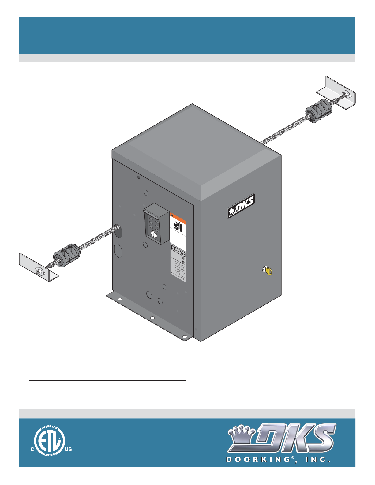
Series 9150
Series 9150
Series 9150
Vehicular Slide Gate Operator
Use this manual for circuit board 4602-010 Revision A or higher.
WARNING
MOVING GATE CAN CAUSE
SERIOUS INJURY OR DEATH
Ope
rate gat
a
nd free of
e
only when gate area i
D
people and obstructions.
o no
or
t
a
operate gat
l
l
ow
chil
Do no
dr
s
en to play i
e
i
.
n si
pat
t
st
h
a
while gat
nd in gat
n g
Rea
ate area
e
e
d owner’s manual and saf
path or walk through
i
s
m
o
ving.
e
t
y
i
ns
t
r
uc
CONFORM
ANSI
S
/
UL-
TO
325
CAN/
CERTI
CSA
FI
ED
C22.
VE
TO
H
2
ICU
N
O.
5
3
C
3
L
247
8
LASS
AR
G
A
T
E
M
O
O
DEL
PE
R
AT
SERI
O
HP
A
L
V
OLTS
AM
PS
M
A
PHASE
X
GATE
LOAD
D
60
o
o
Hz
r
K
in
g
,
In
c
.
,
I
n
g
l
e
w
o
o
d
,
C
A
9150-065-S-9-11
Convenience Open Optional
g
ht
tion
s
.
2
R
Date Installed:
Installer/Company Name:
Phone Number:
Leave Manual with Owner
UL 325 Compliant
Circuit Board
Serial Number
and Revision Letter:
Copyright 2011 DoorKing, Inc. All rights reserved.
TM
Copyright 2009 DoorKing, Inc. All rights reserved.
Page 2

Page 3
Use this manual for the Model 9150 operator with circuit board 4602-010 Rev A or higher ONLY.
Class of Operation Model 9150 - UL 325 Class I, II, III, IV
Type of Gate Vehicular Slide Gates Only
Drive Sprocket Size #40 Chain
Cycles Per Hour 60 Per Hour (Installed level).
Speed Approximately 1 Ft. per Second (Installed level).
Entrapment Protection Primary - Inherent entrapment sensing system (Type A)
Secondary - Provision for connection of a non-contact sensor (Type B1)
and/or a contact sensor (Type B2).
1/2 HP - 115 VAC Single-Phase
1/2 HP - 208/230 VAC Three-Phase
1/2 HP - 460 VAC Three-Phase
1 HP - 115 VAC Single-Phase
1 HP - 208/230 VAC Three-Phase
1 HP - 460 VAC Three-Phase
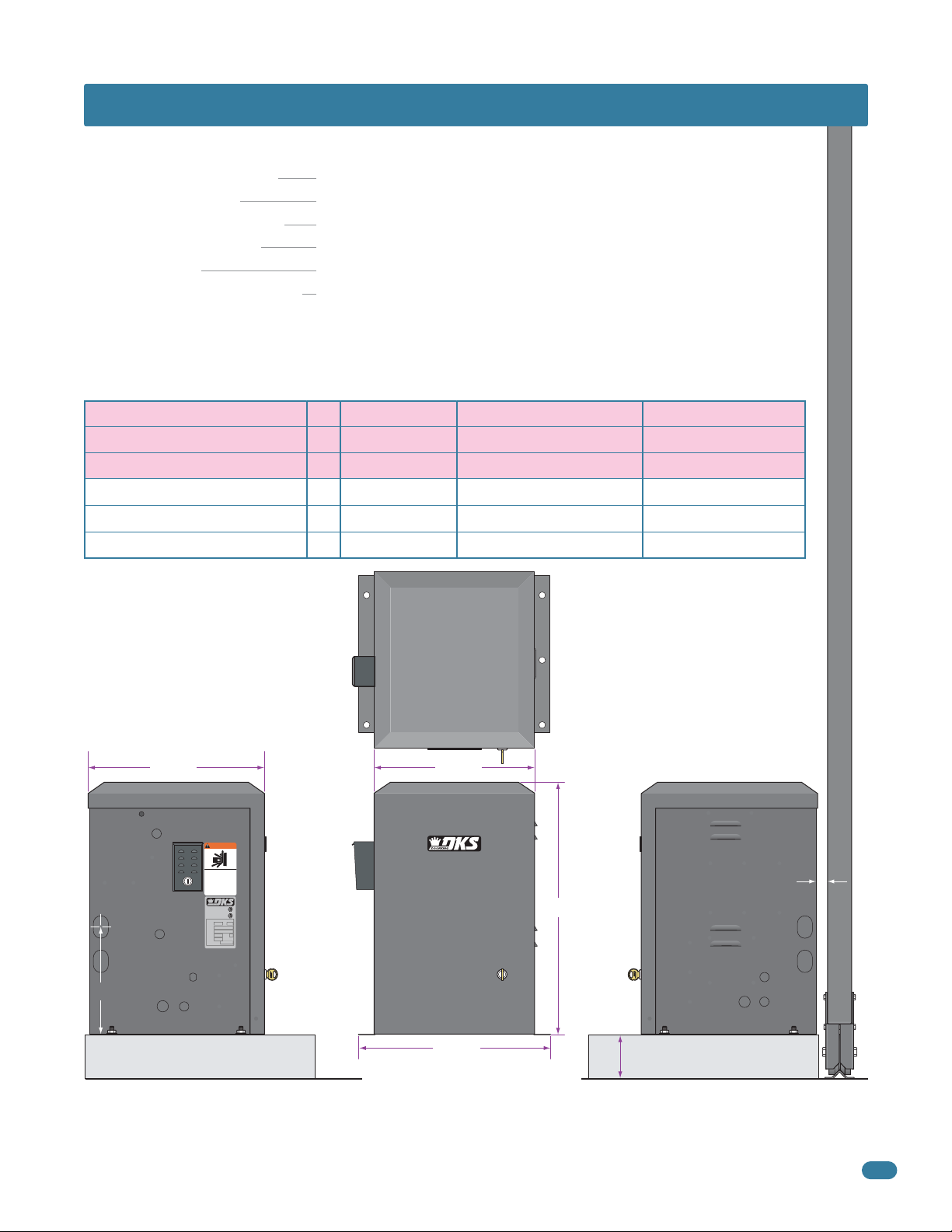
SPECIFICATIONS
Max Gate Length
AmpHorsepower - Voltage - Phase
5.4
2.8
1.35
9.7
5.0
2.5
Installed Level
30 Ft.
30 Ft.
30 Ft.
45 Ft.
45 Ft.
45 Ft.
WITHOUT Convenience Open
Max. Gate Weight
Installed Level
1,000 Lbs.
1,000 Lbs.
1,000 Lbs.
1,500 Lbs.
1,500 Lbs.
1,500 Lbs.
WITH Convenience Open
Max. Gate Weight
Installed Level
800 Lbs.
800 Lbs.
800 Lbs.
1,300 Lbs.
1,300 Lbs.
1,300 Lbs.
Gate Frame
15.25” 16.75”
WARNING
MOVING GATE CAN CAUSE
SERIOUS INJURY OR DEATH
Operate gate only when gate area is in sight
and free of people and obstructions.
Do not allow children to play in gate area
or operate gate.
Do not stand in gate path or walk through
path while gate is moving.
Read owner’s manual and safety instructions.
CONFORMS TO
ANSI/UL-325
CERTIFIED TO
CAN/CSA C22.2 NO. 247
VEHICULAR GATE OPERATOR
CLASS
MODEL
SERIAL
VOLTS PHASE
AMPS 60 Hz
MAX GATE LOAD
DoorKing, Inc., Inglewood, CA
53382
HP
24.75”
Chain Height:
Idler wheels in
10.5”
top position.
Concrete
Pad
DoorKing, Inc. reserves the right to make changes in the products described in this manual without notice and without obligation of DoorKing, Inc. to notify any
persons of any such revisions or changes. Additionally, DoorKing, Inc. makes no representations or warranties with respect to this manual. This manual is
copyrighted, all rights reserved. No portion of this manual may be copied, reproduced, translated, or reduced to any electronic medium without prior written
consent from DoorKing, Inc.
17.75”
4” Minimum
1” Minimum
Concrete
Pad
9150-065-S-9-11
1
Page 4

TABLE OF CONTENTS
SPECIFICATIONS 1
ASTM 2200 Standard for Gate Construction
Important Safety Instructions
Instructions regarding intended installation:
Important Notices
UL325 Entrapment Protection
Glossary
Slide Gate Requirements
Slide Gate Protection
SECTION 1 - INSTALLATION 10
1.1 Hardware for the Gate
1.2 Physical Stops for the Gate
1.3 Types of Gates
1.4 Operator Mounting Positions
1.5 Underground Conduit Requirements
10
10
11
12-15
15
4
4
4
5
6
7
8
9
1.6 Pad, Post or Ceiling Mount without / with J-Box Setup
1.7 Mounting Operator and Chain
1.8 Installation of Warning Signs
1.9 Chain Tray Kit
16
17
18
19
SECTION 2 - AC POWER TO OPERATOR(S) 20
2.1 High Voltage Wire Runs
2.2 High Voltage Terminal Connection
20
21
SECTION 3 - ADJUSTMENTS 22
3.1 4602 Circuit Board Description and Adjustments
3.2 DIP-Switch SW 1 and SW 2 Settings
3.3 Automatic Open / Close Limit Adjustment
3.4 Clutch Adjustment
3.5 Inherent Reverse Sensor Adjustment
22
23-24
25
26
26
2
9150-065-S-9-11
Page 5

TABLE OF CONTENTS
SECTION 4 - ENTRAPMENT AND SAFETY PROTECTION 27
4.1 UL 325 Terminal Description
4.2 Secondary Entrapment Protection Device Locations
4.3 Loop Detector Wiring
27
28-29
30
SECTION 5 - WIRING 31
5.1 Main Terminal Description
5.2 Control Wiring for Single/Primary Operator
5.3 Auxiliary Device Wiring
5.4 Bi-Parting Gates Wiring - Dual Gate Operators
31
32
33
34
SECTION 6 - OPERATING INSTRUCTIONS 35
6.1 AC Power and Reset Switch
6.2 Shutdown Conditions
Soft Shutdown
Hard Shutdown
35
36-37
6.3 Manual Gate Operation
Fail-Safe Manual Release System
Fail-Secure Manual Release System
Emergency Vehicle Access Conditions
37-38
SECTION 7 - OPTIONAL CONVENIENCE OPEN ADJUSTMENTS 39
7.1 Circuit Board (2340) Setup
7.2 DC System Description
7.3 DIP-Switch Settings
39
40
40
SECTION 8 - MAINTENANCE AND TROUBLESHOOTING 41
8.1 Maintenance
8.2 Troubleshooting
8.3 Accessory Items
Model 9150 Wiring Diagrams
41
42-43
44
45-52
9150-065-S-9-11
3
Page 6

ASTM F2200 Standard for Gate Construction
Vehicular gates should be constructed and installed in accordance with ASTM F2200; Standard Specification for Automated
Vehicular Gate Construction. For a copy of this standard, contact ASTM directly at 610-832-9585; service@astm.org; or
www.astm.org.
Important Safety Instructions
WARNING - To reduce the risk of injury or death:
1. READ AND FOLLOW ALL INSTRUCTIONS.
2. Never let children operate or play with gate controls. Keep the remote control away from children.
3. Always keep people and objects away from gate. NO ONE SHOULD CROSS THE PATH OF THE MOVING GATE.
4. Test the operator monthly. The gate MUST reverse on contact with a rigid object or stop or reverse when an object
activates the non-contact sensors. After adjusting the force or the limit of travel, retest the gate operator. Failure to adjust
and retest the gate operator properly can increase the risk of injury or death.
5. Use the emergency release only when the gate is not moving.
6. KEEP GATES PROPERLY MAINTAINED. Read the owner's manual. Have a qualified service person make repairs to gate
hardware.
7. The entrance is for vehicles only. Pedestrians must use separate entrance.
8. SAVE THESE INSTRUCTIONS!
Instructions regarding intended installation:
• Install the gate operator only if:
1. The operator is appropriate for the construction of the gate and the usage class of the gate.
2. All openings of a horizontal slide gate are guarded or screened from the bottom of the gate to a minimum of 6 feet
(1.83 m) above the ground to prevent a 2 ¼ inch (57.2 mm) diameter sphere from passing through the openings
anywhere in the gate, and in that portion of the adjacent fence that the gate covers in the open position.
3. All exposed pinch points are eliminated or guarded.
4. Guarding is supplied for exposed rollers.
• The operator is intended for installation only on gates used for vehicles. Pedestrians must be supplied with a separate
access opening. The pedestrian access opening shall be designed to promote pedestrian usage. Locate the gate such that
persons will not come in contact with the vehicular gate during the entire path of travel of the vehicular gate.
• The gate must be installed in a location so that enough clearance is supplied between the gate and adjacent structures
when opening and closing to reduce the risk of entrapment. Swinging gates should not open into public access areas.
• The gate must be properly installed and work freely in both directions prior to the installation of the gate operator. Do not
over-tighten the operator clutch, pressure relief valve or reduce reversing sensitivity to compensate for a damaged gate.
• For gate operators utilizing Type D protection:
1. The gate operator controls must be placed so that the user has full view of the gate area when the gate is moving.
2. A warning placard shall be placed adjacent to the controls.
3. An automatic closing device (such as a timer, loop sensor, or similar device) shall not be employed.
4. No other activation device shall be connected.
• Controls intended for user activation must be located at least ten feet (10’) away from any moving part of the gate and
where the user is prevented from reaching over, under, around or through the gate to operate the controls. Outdoor or
easily accessible controls should have a security feature to prevent unauthorized use.
• The Stop and/or Reset button must be located in the line-of-sight of the gate. Activation of the reset control shall not
cause the operator to start.
• A minimum of two (2) WARNING SIGNS shall be installed, one on each side of the gate where easily visible.
• For gate operators utilizing a non-contact sensor:
1. See the instructions on the placement of non-contact sensors for each type of application.
2. Care shall be exercised to reduce the risk of nuisance tripping, such as when a vehicle trips the sensor while the gate
is still moving in the opening direction.
3. One or more non-contact sensors shall be located where the risk of entrapment or obstruction exist, such as the
perimeter reachable by a moving gate or barrier.
4
9150-065-S-9-11
Page 7

• For gate operators utilizing contact sensors:
1. One or more contact sensors shall be located where the risk of entrapment or obstruction exist, such as at the
leading edge, trailing edge, and post mounted both inside and outside of a vehicular horizontal slide gate.
2. One or more contact sensors shall be located at the bottom edge of a vehicular vertical lift gate.
3. One or more contact sensors shall be located at the pinch point of a vehicular vertical pivot gate.
4. A hardwired contact sensor shall be located and its wiring arranged so that the communication between the sensor
and the gate operator is not subjected to mechanical damage.
5. A wireless contact sensor such as one that transmits radio frequency (RF) signals to the gate operator for
entrapment protection functions shall be located where the transmission of the signals are not obstructed or
impeded by building structures, natural landscaping or similar obstructions. A wireless contact sensor shall function
under the intended end-use conditions.
6. One or more contact sensors shall be located at the bottom edge of a vertical barrier (arm).
Important Notices
Vehicular gate operator products provide convenience and security. However, gate operators must use high levels of force
to move gates and most people underestimate the power of these systems and do not realize the potential hazards associated with an incorrectly designed or installed system. These hazards may include:
• Pinch points
• Entrapment areas
• Reach through hazards
• Absence of entrapment protection devices
• Improperly located access controls
• Absence of vehicle protection devices
• Absence of controlled pedestrian access
In addition to these potential hazards, automated vehicular gate systems must be installed in accordance with the UL 325
Safety Standard and the ASTM F2200 Construction Standard. Most lay persons are unaware of, or are not familiar with,
these standards. If an automated vehicular gate system is not properly designed, installed, used and maintained, serious
injuries or death can result. Be sure that the installer has instructed you on the proper operation of the gate and gate
operator system.
Be sure that the installer has trained you about the basic functions of the required reversing systems associated with your
gate operating system and how to test them. These include reversing loops, inherent reversing system, electric edges,
photoelectric cells, or other external devices.
• This Owner’s Manual is your property. Keep it in a safe place for future reference.
• Be sure that all access control devices are installed a minimum distance of 10 feet away from the gate and gate
operator, or in such a way that a person cannot touch the gate or gate operator while using the device. If access
control devices are installed in violation of these restrictions, immediately remove the gate operator from service
and contact your installing dealer.
• Loops and loop detectors, photo-cells or other equivalent devices must be installed to prevent the gate from
closing on vehicular traffic.
• The speed limit for vehicular traffic through the gate area is 5 MPH. Install speed bumps and signs to keep
vehicular traffic from speeding through the gate area. Failure to adhere to posted speed limits can result in
damage to the gate, gate operator, and to the vehicle.
• Be sure that all persons who will use the gate system are familiar with the proper use of the gate and gate
operator and are familiar with the possible hazards associated with the gate system.
• Be sure that warning signs are permanently installed on both sides of the gate in an area where they are fully
visible to traffic.
• It is your responsibility to periodically check all entrapment protection devices. If any of these devices are
observed to function improperly, remove the operator from service immediately and contact your installing or
servicing dealer.
• Follow the recommended maintenance schedule.
• Do not allow children to play in the area of the operator or to play with any gate-operating device.
• To remove the gate operator from service, operate the gate to the full open position and then shut off power to
the operator at the service panel.
9150-065-S-9-11
5
Page 8
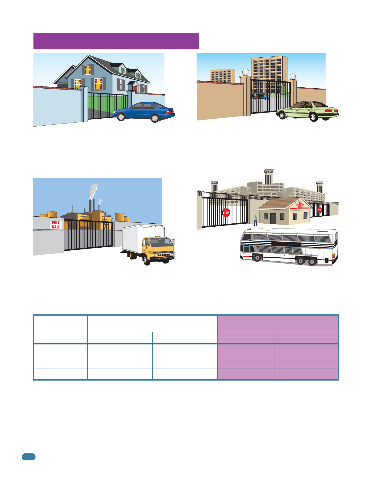
UL 325 Entrapment Protection
Class I
A vehicular gate operator (or system) intended for use in a
home of one-to four single family dwelling, or a garage or
parking area associated therewith.
Class II
A vehicular gate operator (or system) intended for use in a
commercial location or building such as a multi-family
housing unit (five or more single family units) hotel,
garages, retail store or other building servicing the general
public.
Class III Class IV
A vehicular gate operator (or system) intended for use in a
industrial location or building such as a factory or loading
dock area or other locations not intended to service the
general public.
A vehicular gate operator (or system) intended for use in a
guarded industrial location or building such as an airport
security area or other restricted access locations not
servicing the general public, in which unauthorized access
is prevented via supervision by security personnel.
STATE PRISON
This table illustrates the entrapment protection requirements for each of the four UL 325 classes.
UL 325
Classifications
Class I and II
Class III
Class IV
A - Inherent entrapment protection system.
B1 - Provision for connection of, or supplied with, a non-contact sensor (photoelectric sensor or the equivalent).
When used as the PRIMARY device, must be monitored.
B2 - Provision for connection of, or supplied with, a contact sensor (edge device or the equivalent).
When used as the PRIMARY device, must be monitored.
C - Inherent adjustable clutch or pressure relief device.
D - Provision for connection of, or supplied with, an actuating device requiring continuous pressure to maintain
opening or closing motion of the gate.
E - An inherent audio alarm.
6
Horizontal Slide, Vertical Lift, Vertical Pivot Swing and Vertical Barrier (arm)
Primary Protection
A B1, B2 or D A, B1, B2, C or D A or C
A, B1 or B2 A, B1, B2, D or E A, B1, B2, C or D A, B1, B2 or C
A, B1, B2 or D A, B1, B2, D or E A, B1, B2, C, D or E A, B1, B2, C or D
Secondary Protection Primary Protection Secondary Protection
9150-065-S-9-11
Page 9

Glossary
GATE - A moving barrier such as a swinging, sliding, raising, lowering, or the like, barrier, that is a stand-alone passage
barrier or is that portion of a wall or fence system that controls entrance and/or egress by persons or vehicles and
completes the perimeter of a defined area.
RESIDENTIAL VEHICULAR GATE OPERATOR – CLASS I - A vehicular gate operator (or system) intended for use in a home
of one-to four single family dwelling, or garage or parking area associated therewith.
COMMERCIAL / GENERAL ACCESS VEHICULAR GATE OPERATOR - CLASS II - A vehicular gate operator (or system)
intended for use in a commercial location or building such as a multi-family housing unit (five or more single family units),
hotels, garages, retail store, or other building servicing the general public.
INDUSTRIAL / LIMITED ACCESS VEHICULAR GATE OPERATOR - CLASS III - A vehicular gate operator (or system)
intended for use in an industrial location or building such as a factory or loading dock area or other locations not intended
to service the general public.
RESTRICTED ACCESS VEHICULAR GATE OPERATOR - CLASS IV - A vehicular gate operator (or system) intended for use in
a guarded industrial location or building such as an airport security area or other restricted access locations not servicing
the general public, in which unauthorized access is prevented via supervision by security personnel.
VEHICULAR BARRIER (ARM) OPERATOR (OR SYSTEM) - An operator (or system) that controls a cantilever type device (or
system), consisting of a mechanical arm or barrier that moves in a vertical arc, intended for vehicular traffic flow at
entrances or exits to areas such as parking garages, lots or toll areas.
VEHICULAR HORIZONTAL SLIDE-GATE OPERATOR (OR SYSTEM) - A vehicular gate operator (or system) that controls a
gate which slides in a horizontal direction that is intended for use for vehicular entrance and exit to a drive, parking lot, or
the like.
VEHICULAR SWING-GATE OPERATOR (OR SYSTEM) - A vehicular gate operator (or system) that controls a gate which
moves in an arc in a horizontal plane that is intended for use for vehicular entrance and exit to a drive, parking lot, or the
like.
SYSTEM - In the context of these requirements, a system refers to a group of interacting devices intended to perform a
common function.
WIRED CONTROL - A control implemented in a form of fixed physical interconnections between the control, the associated
devices, and an operator to perform predetermined functions in response to input signals.
WIRELESS CONTROL - A control implemented in means other than fixed physical interconnections (such as radio waves or
infrared beams) between the control, the associated devices, and an operator to perform predetermined functions in
response to input signals.
INHERENT ENTRAPMENT PROTECTION SYSTEM - A system, examples being a motor current or speed sensing system,
which provides protection against entrapment upon sensing an object and is incorporated as a permanent and integral part
of the operator.
EXTERNAL ENTRAPMENT PROTECTION DEVICE - A device, examples being an edge sensor, a photoelectric sensor, or
similar entrapment protection device, which provides protection against entrapment when activated and is not incorporated
as a permanent part of an operator.
ENTRAPMENT - The condition when an object is caught or held in a position that increases the risk of injury.
9150-065-S-9-11
7
Page 10
Slide Gate Requirements
The operator is intended for installation only on gates used for vehicles. Pedestrians must be supplied with a separate
access opening. The pedestrian access opening shall be designed to promote pedestrian usage. Locate the gate such that
persons will not come in contact with the vehicular gate during the entire path of travel of the vehicular gate.
(ref. UL 325 56.8.4.b)
Adjacent fence that covers open gate position.
X X X X X X X X X X X X X X X X X X X X X X X X X X X X X X X X X X X X X X X X X X X X X X X X X X X X
High Risk of Entrapment Area
X X X
All openings of a horizontal slide gate are
guarded or screened from the bottom of the gate to a
minimum of six (6) feet (1.83 m) above the ground to
prevent a 2 1/4 inch (57.2 mm) diameter sphere from
passing through the openings anywhere in the gate
and in that portion of the adjacent fence that the gate
covers in the open position.
(ref. ASTM F2200-11a, 6.1.2)
Compliant openings less than 2 1/4”.
X X X X X X X X X X X X X X X X X X X X X X X X X X X X X X X X X X X X X X X X X X X X X X X X X X X X X X X
Closed Gate
X X XX X XX X XX X XX X X X XX X X
Gate Frame and Adjacent Fence Area
Non-compliant openings wider than 2 1/4”.
Less than 2 1/4”
Screened Wire Mesh
Note: Install
screened wire
mesh to a
non-compliant
gate AND
non-compliant
adjacent fence
that covers
open gate
72” (6 ft) minimum 6 ft minimum
position
(See above).
A gap, measured in the horizontal
plane parallel to the roadway, between
a fixed stationary object nearest the
roadway (such as a gate support post)
and the gate frame when the gate is in
either the fully open position or the
fully closed position, shall not exceed
2 1/4 inch (57.2 mm).
(ref. ASTM F2200 6.1.4)
Note: A filler post or barrier
may need to be installed in the
gap area to reduce the distance
to 2 1/4 inches or less.
A contact sensor should be
installed in this area for
safety.
(See
A
on next page).
Gate Frame
Gate Support Post
2 1/4” maximum gap area High Risk of Entrapment Area
Gate Frame and Adjacent Fence Area
8
9150-065-S-9-11
Page 11
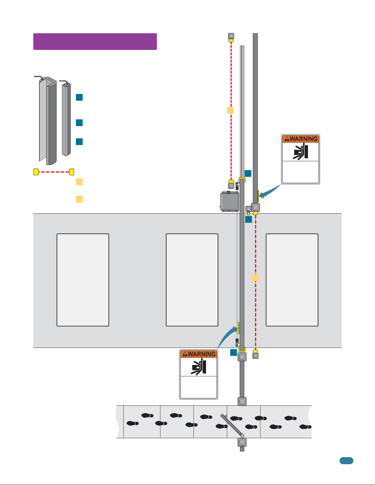
Slide Gate Protection
Entrapment protection devices are required to reduce the risk of injury. Install
sensors where the risk of entrapment or obstruction exists while gate is moving.
Individual requirements will vary.
Contact Sensor (Reversing Edges)
Installed on the fence to help minimize the potential of
A
entrapment between the gate and fence. A filler post or
barrier may need to be installed between fence and gate.
Helps minimize the potential of entrapment during
B
the back travel of the gate.
Minimizes the potential of the gate closing on
C
vehicular or other traffic that loops cannot sense.
Non-Contact Sensors (Photo Sensors)
Minimizes the potential of the gate closing on
1
vehicular or other traffic that loops cannot sense.
Helps minimize the potential of entrapment during
2
the back travel of the gate.
2
Fence
Permanently mounted
and easily visible from
either side of the gate.
Moving Gate Can Cause
Serious Injury or Death
KEEP CLEAR! Gate may move at any time
without prior warning.
B
Do not let children operate the gate or play
in the gate area.
This entrance is for vehicles only.
Pedestrians must use separate entrance.
A
Warning Signs
Automatic
Exit Loop
(Optional) will
provide an open
command to the
gate operator(s)
when a vehicle
is exiting the
property.
See pages 27-30 for typical layout locations.
Warning Signs
Permanently mounted
and easily visible from
either side of the gate.
Separate
Pedestrian
Walkway
Located so pedestrians
cannot come in contact
with the vehicular gate.
Reverse
Secure Side of Gate
Loop
Minimizes the
potential of the
gate closing when
a vehicle is
present. Number
and placement of
loops is dependent
on the application.
Moving Gate Can Cause
Serious Injury or Death
KEEP CLEAR! Gate may move at any time
without prior warning.
Do not let children operate the gate or play
in the gate area.
This entrance is for vehicles only.
Pedestrians must use separate entrance.
C
Closed Gate
1
Fence
Reverse
Loop
Minimizes the
potential of the
gate closing when
a vehicle is
present. Number
and placement of
loops is dependent
on the application.
Non-Secure Side of Gate
9150-065-S-9-11
9
Page 12
SECTION 1 - INSTALLATION
Prior to beginning the installation of the slide gate operator, we suggest that you become familiar with the
instructions, illustrations, and wiring guide-lines in this manual. This will help insure that your installation is
performed in an efficient and professional manner compliant with UL 325 safety and ASTM F2200 construction
standards.
The proper installation of the vehicular slide gate operator is an extremely important and integral part of the
overall access control system.
Check all local building ordinances and building codes prior to installing
this operator. Be sure your installation is in compliance with local codes.
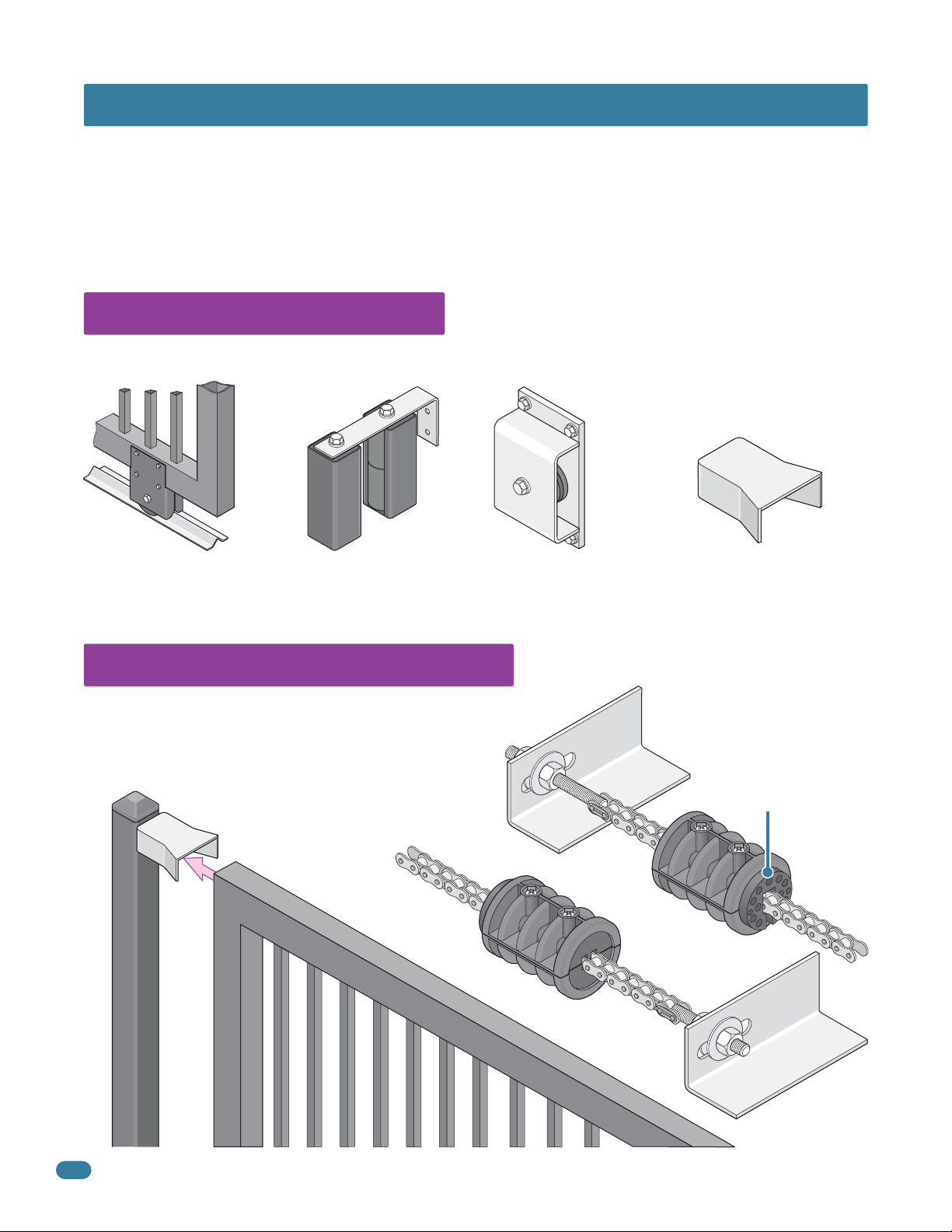
1.1 Hardware for the Gate
Good hardware is essential for proper operation of a sliding gate. DoorKing has a full line of gate hardware products that will
ensure safe, reliable and long lasting gate operation. The gate must be properly installed and roll smoothly in both directions.
Roller Bearing V-Wheels
with Protective Cover - Helps
to minimize a pinch point on
the gate’s wheel and V-rail.
Guide Rollers with
Protective Covers - Helps
to minimize a pinch point
on the gate.
Endless Idler Assembly with
Protective Cover - Helps to
minimize a pinch point for a
180° chain return.
1.2 Physical Stops for the Gate
The 9150’s automatic open/close gate limits must have a physical
stop on the open and close positions of the gate. This can be the
use of end posts with gate end retainers or chain stops, depending
on the mounting position of the operator. Chain stops DO NOT
meet the ASTM F2200 requirements.
Gate End Retainer
End
Post
Gate End Retainer - Helps stabilize
the end of the gate in the open or
closed position. Recommended for
all slide gate applications.
Rubber bumper faces toward
operator. it will make contact
with the operator housing
during the initial automatic
“Multiple gate cycling” to
set the open and close
gate position.
Chain Stops
Gate
10
9150-065-S-9-11
Page 13
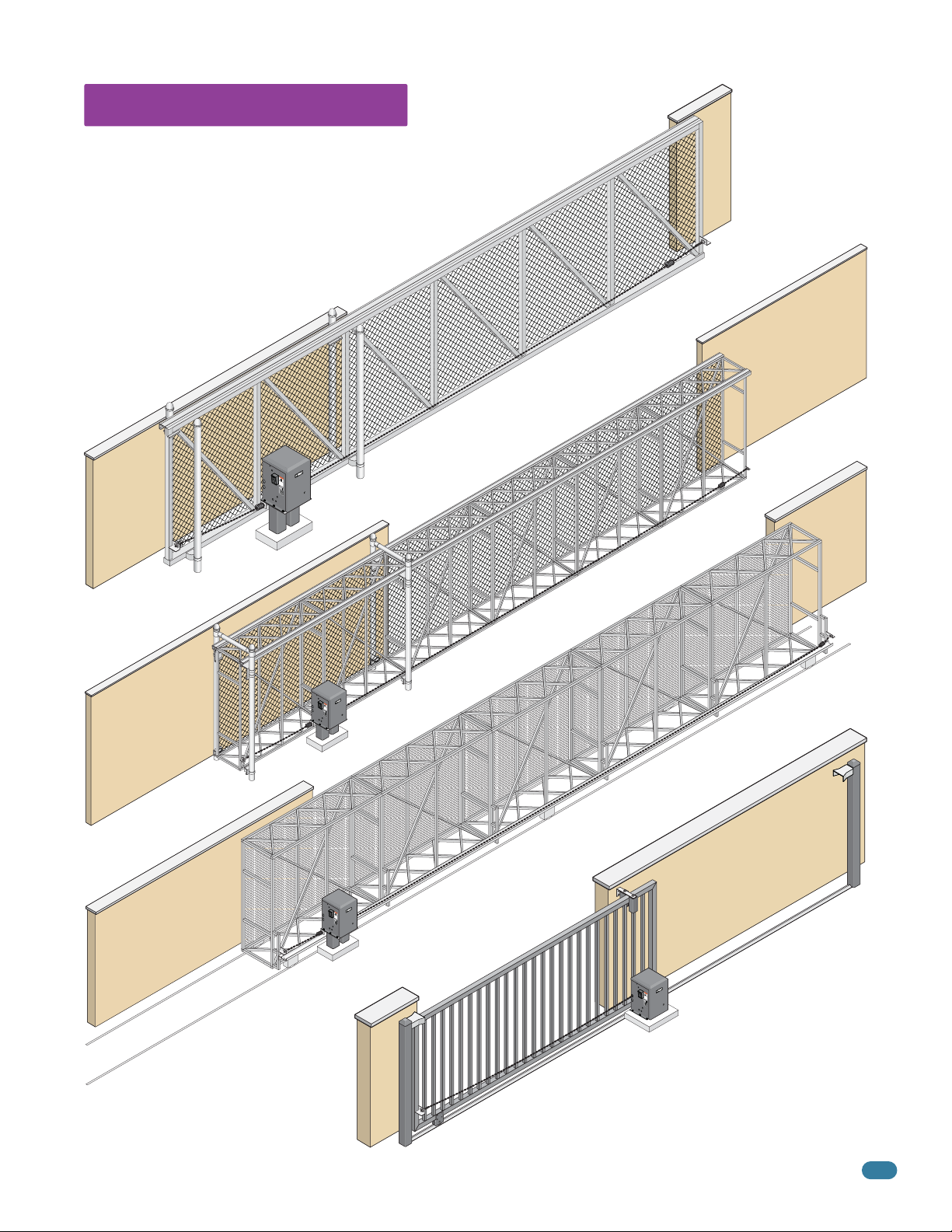
1.3 Typical Gate Types
The Model 9150 operator is designed to be installed on these gate types.
See the next 4 pages for specific operator mounting positions. Individual
installations and physical stops can vary.
• 1500 lb. max. weight per gate (1 HP).
• Single Operator - 45 ft max. gate length (1 HP).
• Dual Operators - 90 ft max. total gate length (1 HP).
• Chain tray recommended for gates
longer than 20 ft using front or
center post mount
installations ONLY.
Front position with post mount shown.
Cantilever
WA
R
N
I
N
G
M
O
V
SE
IN
RI
G
OUS
G
A
O
T
p
E
e
I
r
a
NJ
a
C
t
n
e
d
A
g
URY
f
a
N
r
t
e
e
e
o
C
o
n
f
A
l
OR
D
y
p
o
U
e
w
o
n
h
S
p
o
e
o
l
t
e
n
E
r
DE
a
a
o
g
l
l
n
p
a
o
d
e
t
w
ATH
e
r
o
a
a
c
b
t
r
h
e
s
e
i
D
t
g
a
l
r
d
a
o
u
i
r
s
t
c
e
e
n
t
n
i
.
i
o
n
o
p
t
t
n
a
o
s
s
t
s
i
p
h
t
g
.
a
h
l
n
w
a
t
y
d
h
i
i
i
n
l
n
e
g
g
R
g
a
a
a
e
t
t
t
a
e
e
e
d
a
p
i
s
o
r
a
e
w
t
m
a
h
n
o
o
e
v
r
r
i
’
w
n
s
g
m
a
.
l
k
a
n
t
h
u
r
a
o
l
a
u
g
n
h
d
s
a
f
e
t
y
i
n
s
t
r
u
c
t
i
o
n
s
.
C
O
N
F
A
O
N
R
S
M
I
/
S
U
L
T
O
3
C
2
E
5
R
V
T
C
E
I
F
A
H
I
N
E
I
D
/
C
C
5
U
S
T
3
C
3
O
A
L
8
L
2
A
C
A
R
2
S
2
S
G
.
2
A
N
T
O
M
E
.
O
O
2
D
4
P
E
7
E
L
R
A
S
T
E
H
O
R
P
R
I
A
L
V
O
L
T
S
A
M
P
S
M
A
P
X
H
G
A
A
S
T
E
E
L
O
D
A
6
o
D
0
o
H
r
K
z
i
n
g
,
In
c
.
,
I
n
g
le
w
o
o
d
,
C
A
Chain stops used as physical stops for gate.
Box Frame Cantilever
Box Frame Roller
Front position with post mount shown.
Chain stops used as physical stops for gate.
W
A
R
N
I
N
G
M
O
V
S
I
N
E
R
G
I
O
G
U
A
O
T
S
p
E
e
I
r
a
N
a
C
t
n
e
J
d
A
g
U
f
a
N
r
t
e
R
e
e
o
C
Y
o
n
f
A
l
D
y
p
O
o
U
e
w
o
R
n
h
S
p
o
e
o
l
t
e
E
n
r
D
a
a
o
g
l
E
l
n
p
a
o
d
e
t
w
A
e
r
o
a
T
a
c
b
t
r
h
e
s
H
e
i
D
t
l
g
a
d
r
a
o
u
r
i
s
t
e
c
e
n
n
t
i
.
o
i
n
p
o
t
t
a
n
o
s
s
t
s
i
h
t
p
g
.
a
l
h
n
a
w
t
y
d
h
i
i
i
n
l
n
e
g
g
R
g
a
a
a
e
t
t
t
a
e
e
e
d
a
p
i
s
o
r
a
e
w
t
m
a
h
n
o
o
e
v
r
r
i
’
n
s
w
g
m
a
.
l
k
a
n
t
h
u
r
a
o
l
u
a
g
n
h
d
s
a
f
e
t
y
i
n
s
t
r
u
c
t
i
o
n
s
.
C
O
N
F
O
A
R
N
M
S
I
S
/
U
T
L
O
3
C
C
2
A
E
5
N
R
/
T
C
I
F
S
I
A
E
D
C
V
2
T
2
E
O
.
H
2
I
N
C
O
5
U
3
.
C
3
L
L
8
2
A
2
A
4
R
7
S
S
G
A
T
MO
E
O
D
P
E
E
L
R
A
S
T
E
H
O
R
P
R
I
A
L
V
O
L
T
S
A
M
P
S
MA
P
X
H
G
A
A
S
T
E
E
L
O
D
A
6
o
0
D
o
H
r
K
z
i
n
g
,
I
n
c
.
,
I
n
g
l
e
w
o
o
d
,
C
A
V-Rail V-Wheel Ornamental
Front position with post mount and chain tray shown.
Chain stops used as physical stops for gate.
W
A
RN
I
N
G
M
O
V
S
I
N
E
R
G
I
O
G
U
A
O
T
S
p
E
e
I
r
a
N
a
C
t
n
e
J
d
A
g
U
f
a
N
r
t
e
R
e
e
o
C
Y
o
n
f
A
l
D
y
p
O
o
U
e
w
o
R
n
h
S
p
o
e
o
l
t
e
E
n
r
D
a
a
o
g
l
E
l
n
p
a
o
d
e
t
w
A
e
r
o
a
T
a
c
b
t
r
h
e
s
H
e
i
D
t
l
g
a
d
r
a
o
u
r
i
s
t
e
c
e
n
n
t
i
.
o
i
n
p
o
t
t
a
n
o
s
s
t
s
i
h
t
p
g
.
a
l
h
n
a
w
t
y
d
h
i
i
i
n
l
n
e
g
g
R
g
a
a
a
e
t
t
t
a
e
e
e
d
a
p
i
s
o
r
a
e
w
t
m
a
h
n
o
o
e
v
r
r
i
’
n
s
w
g
m
a
.
l
k
a
n
t
h
u
r
a
o
l
u
a
g
n
h
d
s
a
f
e
t
y
i
n
s
t
r
u
c
t
i
o
n
s
.
C
O
N
F
O
A
R
N
MS
S
I
/
U
T
L
O
3
C
C
2
A
E
5
N
R
/
T
C
I
F
S
I
A
E
D
C
V
2
T
2
E
O
.
H
2
I
N
C
O
5
U
3
.
C
3
L
L
8
2
A
2
A
4
R
7
S
S
G
A
T
M
E
O
O
D
P
E
E
L
R
A
S
T
E
H
O
R
P
R
I
A
L
V
O
L
T
S
A
M
P
S
MA
P
X
H
G
A
A
S
T
E
E
L
O
D
A
6
o
0
D
o
H
r
K
z
i
n
g
,
I
n
c
.
,
I
n
g
l
e
w
o
o
d
,
C
A
W
A
R
N
I
N
G
M
O
V
S
I
N
E
R
G
I
G
O
U
AT
O
S
p
E
e
I
r
at
N
a
CA
n
e
J
d
g
f
UR
a
N
r
t
e
e
e
o
C
Y
o
n
f
AU
l
D
y
p
O
o
w
e
o
R
n
h
S
p
o
en
o
le
t
E
r
D
a
a
o
g
l
E
l
n
p
at
o
d
e
w
A
e
r
o
a
a
T
c
b
t
r
h
e
st
H
ea
il
D
g
r
d
at
o
uc
is
r
e
e.
n
n
t
i
o
i
n
p
t
o
t
a
n
o
s
s
t
s
i
h
t
g
p
.
an
h
l
w
ay
t
d
h
in
il
i
n
e
g
R
g
g
a
a
at
e
t
t
ad
e
e
e
ar
p
is
o
a
ea
m
w
t
h
n
o
o
e
v
r
r
i
’
n
s
w
g
m
a
.
l
k
a
n
t
h
u
r
a
o
l
u
a
g
n
h
d
s
a
f
e
t
y
in
s
t
r
u
ct
i
o
n
s
.
C
O
N
F
O
A
R
N
M
S
I
S
/
U
T
L
O
3
C
C
2
A
E
5
N
R
/
T
C
I
F
S
I
A
E
D
C
V
2
T
2
E
O
.
H
2
I
N
C
O
5
U
3
.
C
3
L
8
2
L
2
A
4
A
7
R
S
S
G
A
T
M
E
O
O
D
P
E
E
L
R
A
S
T
E
H
O
R
P
R
I
A
L
V
O
L
T
S
A
M
P
S
M
A
P
X
H
G
A
A
S
T
E
E
L
O
D
A
6
o
D
0
o
H
r
K
z
i
n
g
,
I
n
c
.
,
I
n
g
l
e
w
o
o
d
,
C
A
Front position with concrete pad shown.
9150-065-S-9-11
Gate end retainers on end posts used as physical stops for gate.
11
Page 14
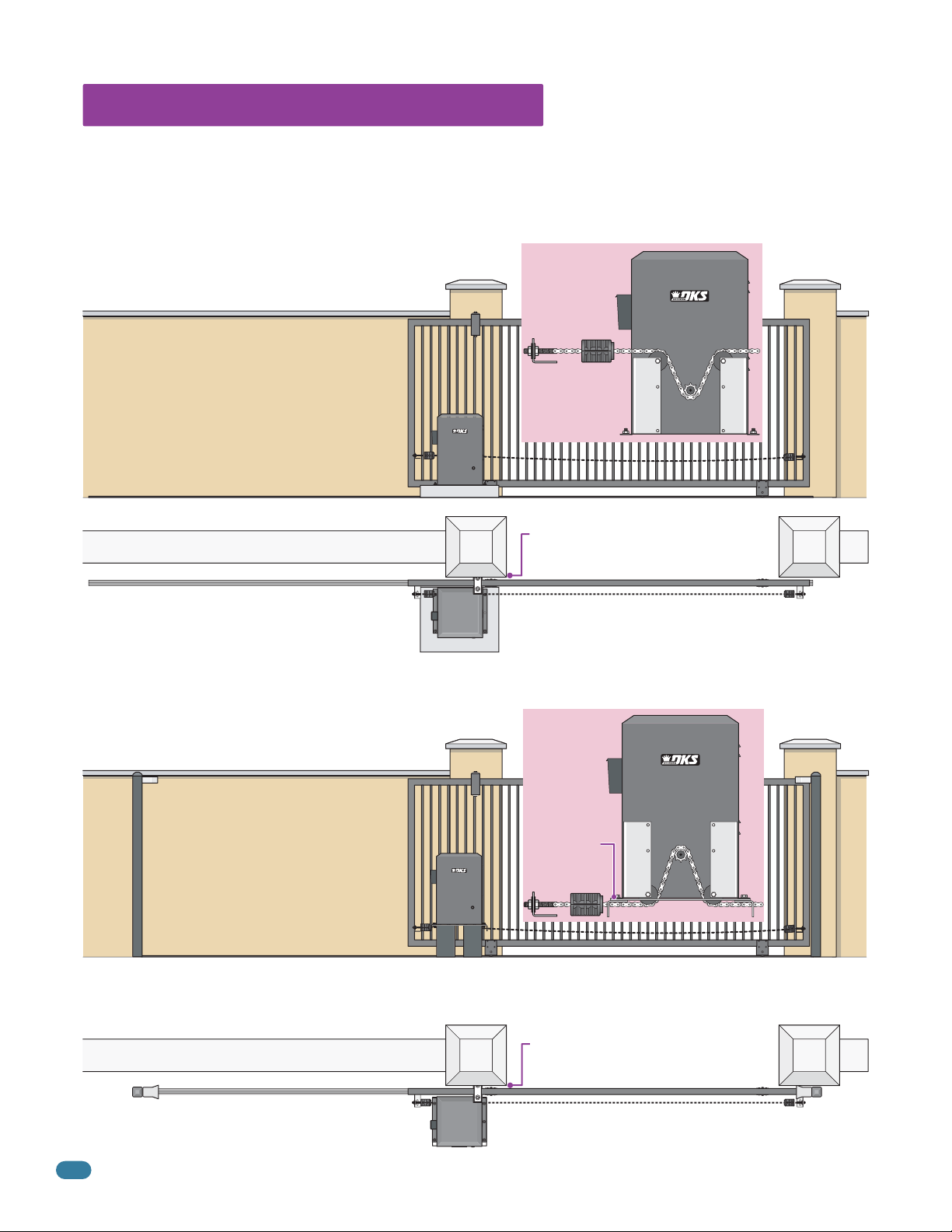
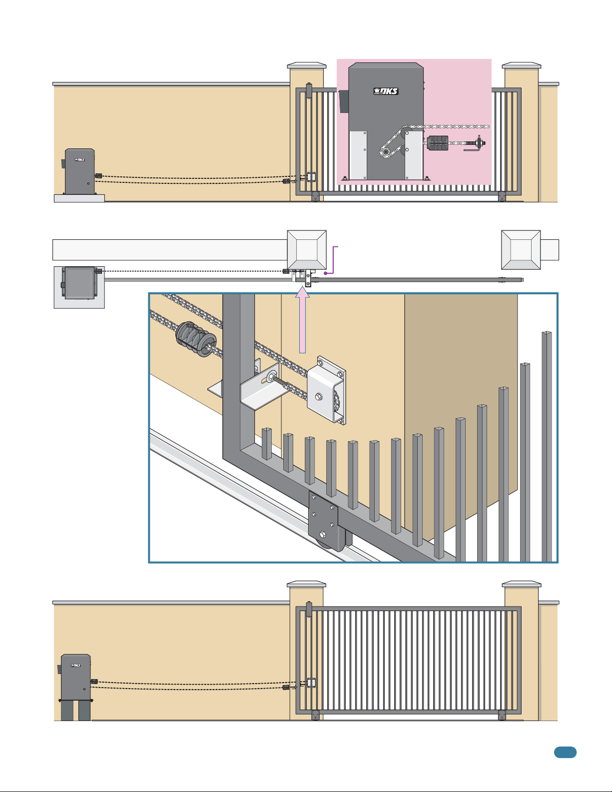
1.4 Operator Mounting Positions
The Model 9150 operator is designed to be installed in the front, rear, center or ceiling mounting positions shown on this page
and the next 3 pages. V-wheel V-rail ornamental gates are shown as examples but other gate types on the previous page can
use the same mounting setups. Once the mounting position has been determined, the chain idler wheels may need to be
adjusted BEFORE the operator is mounted. Physical stops MUST be used in the open AND close positions for ANY gate
installation (Chain stops, end posts with gate end retainers or a wall that the gate comes in contact with).
Front Position with Concrete Pad
Chain Setup
Standard method of installation.
• Operator’s chain idler wheels are factory set
for the front position.
• Remove only the top chain knockouts from
Chain
Stop
Chain Idler
Wheels
each side of the operator.
• Chain stops or gate end retainer can be
used as the physical stop for the gate
(Chain stops are shown).
A filler post or barrier may need to be
Top View
installed between the gate and wall area
(See page 8 for more information).
Front Position with Post Mount
Raises operator and allows different chain heights. Optional chain tray kit can be used and is recommended for gates over 20 ft,
supports the chain’s weight and helps prevent chain “stretching”.
See page 19 for more information.
Gate End Retainer
Chain Setup
• Set operator chain idler wheels in the
bottom position.
• DO NOT remove chain knockouts.
• Chain stops with base plate stop
brackets or gate end retainer can be
Base Plate
Stop Bracket
Chain
Stop
Chain Idler
Wheels
used as the physical stop for the gate
(Both are shown, only one type is
needed).
Additional hardware required. Post base plate (P/N 2600-495) 6 x 6 steel posts not available from DoorKing.
Base plate stop brackets (P/N 2600-970) bolts on post base plate when using chain stops.
Optional chain tray kit (P/N 2601-270 10 ft section) and additional chain #40 (P/N 2600-442 - 20 ft. per box) may be needed.
Top View
Gate End Retainer
12
A filler post or barrier may need to be
installed between the gate and wall area
(See page 8 for more information).
Gate End
Retainer
9150-065-S-9-11
Page 15
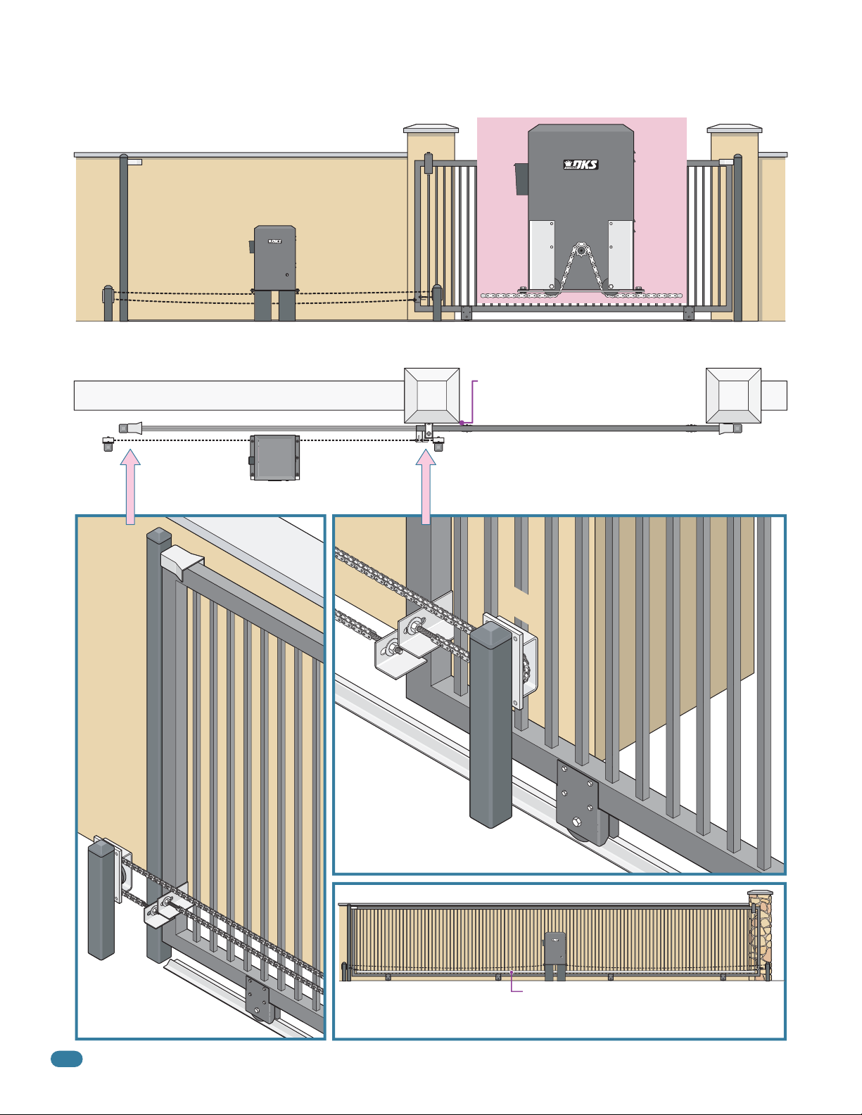
Rear Position with Concrete Pad
Hides the chain from outside the property looking in.
• Set one chain Idler wheel at the top and one in the
center position on one side of the operator.
• Remove both chain knockouts from one side of the
operator.
• Chain stops or gate end retainer can be
used as the physical stop for the gate
(Chain stops are shown).
Additional hardware required. Endless idler assembly (P/N 2600-818) and
additional chain #40 (P/N 2600-442 - 20 ft. per box) may be needed.
Chain Setup
Chain Idler
Wheels
Chain
Stop
Top View
A filler post or barrier may need to be
installed between the gate and wall area
(See page 8 for more information).
Endless
Idler
See page 18 for
more information
about endless idlers.
Rear Position with Post Mount
Hides the chain from outside the property looking in.
• Chain setup is the same as above.
Additional hardware required. Post base plate (P/N 2600-495) 6 x 6 steel posts not available from DoorKing.
9150-065-S-9-11
13
Page 16
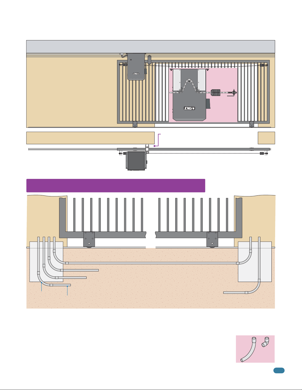
Center Position with Post Mount Hides the chain from outside the property looking in. Optional chain tray
kit can be used and is recommended for gates over 20 ft, supports the chain’s weight and helps prevent chain “stretching”.
See page 19 for more information.
• Set operator chain idler wheels in the
bottom position.
• DO NOT remove chain knockouts.
Additional hardware required. Post base plate (P/N 2600-495) 6 x 6 steel posts not available from DoorKing. Endless idler
assembly (P/N 2600-818). Additional chain #40 (P/N 2600-442 - 20 ft. per box). Gate end retainer (P/N 1204-004).
Top View
Chain
Setup
Chain Idler
Wheels
A filler post or barrier may need to be
installed between the gate and wall area
(See page 8 for more information).
Note: Chain stops CANNOT be used for this installation.
End post with a gate end retainer must be installed as the
physical stop if gate does not have any other means of a
physical stop in the open and close position.
Gate End
Retainer
End Post
Endless
Idler
Endless
Idler
See page 18 for
more information
about endless idlers.
Gate in Close Position
Gate shown in open position.
Gate in Open Position
14
Optional Chain Tray Kit
for Long Gates
Optional chain tray kit (P/N 2601-270) can
be used and is recommended for gates over
20 ft, see page 19 for more information.
9150-065-S-9-11
Page 17
F
ront or Rear Position Upside Down
Can be mounted on the ceiling to conserve floor space.
Ceiling
• Operator’s setup is the same as the front
position or rear position with concrete pad
shown on page 12 and 13.
(Front upside down position shown here).
• Junction box connection is used for the
ceiling mount installation.
Note: There are NO fluids in the
operator that can leak out.
Top View
Operator
Bottom
Chain Idler
Wheels
A filler post or barrier may need to be
installed between the gate and wall area
(See page 8 for more information).
Chain Setup
Chain
Stop
1.5 Underground Conduit Requirements
Primary
Operator
Position
DoorKing’s Primary/Secondary Interconnection Cable (Dual Operator Application Only)
(Secondary Power and Communication wires)
Control and/or P.A.M.S. Wires (Low Voltage wire insulation)
Loop Lead-In Wires (Low Voltage wire insulation)
AC Input Power (High Voltage wire insulation)
Sweeps
3/4 Inch Conduit Recommended
• The conduit requirements are for a typical slide gate operator installation (the secondary operator is shown for those
applications where a secondary operator may be used). The conduit requirements for your application may vary from
this depending on your specific needs.
• Use only sweeps for conduit bends. Do not use 90° elbows as this will make wire pulls very difficult and can cause
damage to wire insulation.
• DoorKing recommends using 3/4-inch conduit.
• Be sure that all conduits are installed in accordance with local codes.
• Never run low voltage rated wire insulation in the same conduit as high voltage rated wire insulation.
AC Input Power (High Voltage wire insulation)
Secondary
Operator
Position
Concrete
Pad
Sweep
YES
Elbow
NO
9150-065-S-9-11
15
Page 18

1.6 Pad, Post or Ceiling Mount without/with J-Box Setup
Pad Mount with Conduit
1” minimum from operator housing to gate.
2.5”
Conduit Area
Concrete pad
14.5”
8.5”
MUST be level.
Electronic Box
Center
Concrete Pad
26”
Post Mount with Conduit
1” minimum from operator housing to gate.
14”
Min.
Conduit area
inside 6 x 6
post.
Base Plate
Conduit area
inside 6 x 6
post.
6.5”
P/N 2600-495
Note: Weld the posts to the base plate and mount
assembly into concrete BEFORE attaching the
operator. Conduit runs up through 6 x 6 steel posts.
1.5”
24”
Min.
21.5”
Concrete Foundation
4” min. above ground.
Underground depth of the
concrete pad is determined
by soil conditions and local
building codes. Reinforced
concrete recommended.
Base Plate
MUST be level.
4” min. above ground.
Underground depth of the
concrete foundation is
determined by soil
conditions and local
building codes. Reinforced
concrete recommended.
Concrete Pad
Concrete Foundation
Conduit
Conduit
Pad, Post or Ceiling Mount Connected with Junction Boxes
All wire connections can be
made on either side of the
operator housing after it
has been installed.
Operator MUST
be level.
Note: Operator must be mounted
1” min. away from gate.
16
Low
High
Volt
Volt
Pad, post or
Conduit Conduit
ceiling mount
Never run high
voltage and low
voltage in the
same conduit.
Low
High
Volt
Volt
1/2
1/2
Fail Secure
Key Lock
3/4
1/2
WARNING
MOVING GATE CAN CAUSE
SERIOUS INJURY OR DEATH
Operate gate only when gate area is in sight
and free of people and obstructions.
Do not allow children to play in gate area
or operate gate.
Do not stand in gate path or walk through
path while gate is moving.
Read owner’s manual and safety instructions.
CONFORMS TO
ANSI/UL-325
CERTIFIED TO
CAN/CSA C22.2 NO. 247
VEHICULAR GATE OPERATOR
CLASS
MODEL
SERIAL
VOLTS PHASE
AMPS 60 Hz
MAX GATE LOAD
DoorKing, Inc., Inglewood, CA
53382
HP
Conduit Knock-Out Sizes
1/2
1/2
3/4
9150-065-S-9-11
Page 19

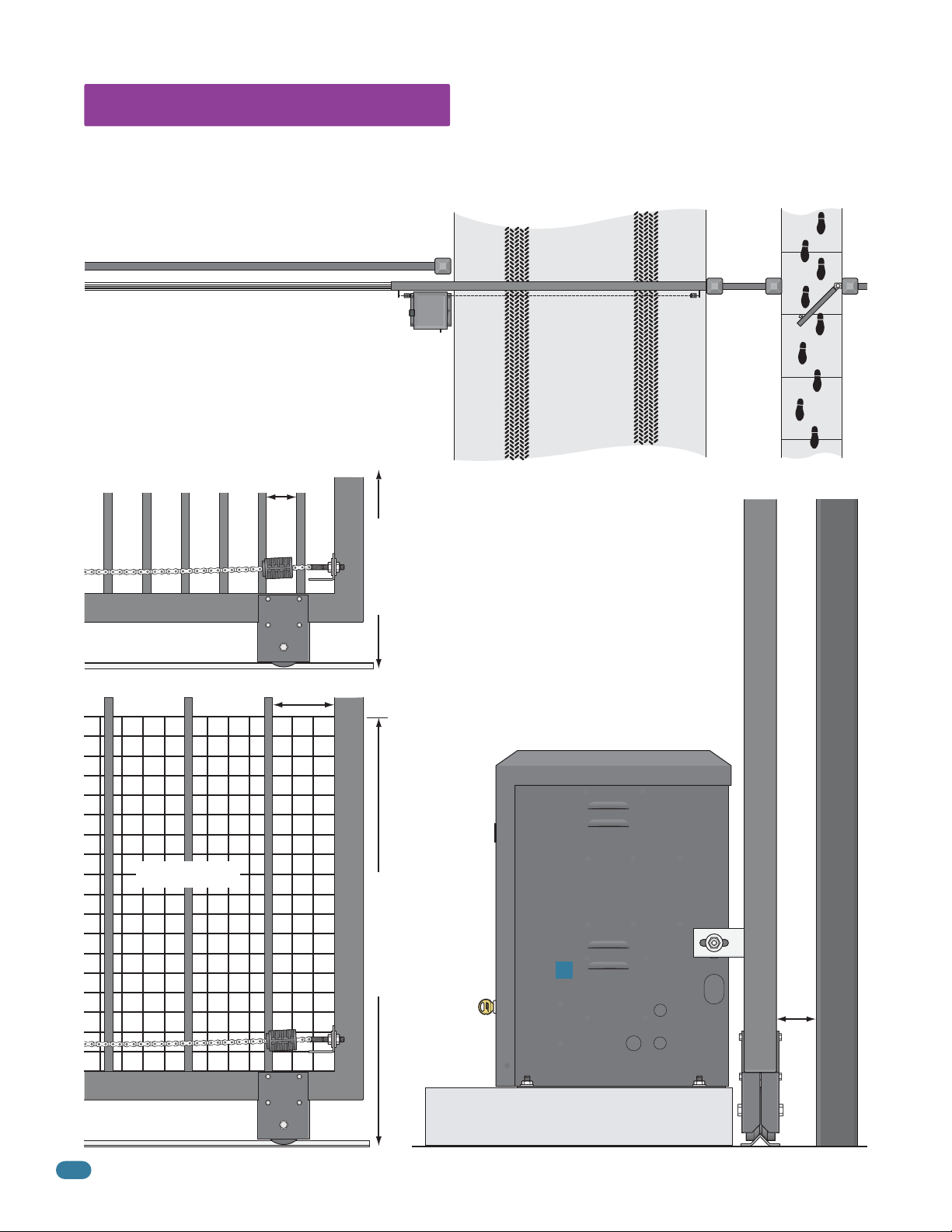
1.7 Mounting Operator and Chain
NO
NO
YES
YES
NO
Prior to mounting the operator, be sure that the correct chain knockouts have been removed and chain idler wheels are in the
correct position (top, center or bottom).
Fail-Secure Manual Release Kit Installation Note: It is easier to install the 2600-865 fail-secure manual release kit before
mounting the operator and attaching the chain. Refer to the instruction sheet supplied with the kit for installation.
Positioning Operator and Chain Brackets
1” minimum from operator housing to gate.
Chain
Bracket
Lines up
with Idler
Wheels
Correct
Chain
Bracket
Height
Chain Idler Wheels
YES
YES
Chain Idler Wheels
Operator MUST be
parallel to gate!
Chain bracket MUST
line up with chain
idler wheels!
Chain brackets MUST be
mounted so the chain
remains the same height
as it is on the idler wheels!
Correct
Chain
Bracket
Chain idler
wheels in
top position.
Height
10.5”10.5”10.5”
Chain Bracket
NO
NO
NO
Gate
Frame
Operator NOT
parallel to gate.
Chain bracket
does NOT
align with
idler wheels.
Chain brackets
positioned
too high.
Chain brackets
positioned
too low.
Lock
Washer
Washers
9150-065-S-9-11
Attaching Operator
to Concrete
DoorKing recommends a
3/8
minimum of four (4) 3/8” x 2”
sleeve anchors (not supplied).
Attaching Operator
to Post Base Plate
Use six (6) 1/2”-13 x 1 1/2”
bolts, lockwashers and nuts
(not supplied).
Option 1
Connect Chain Bracket
to Gate.
around bracket. Chain nut
and chain bolt should not
protrude past gate frame.
Connect Chain to Chain Bracket.
Connect chain to chain bolt with
master link. Adjust the chain nuts to
tighten the chain. The chain should sag no
more than one (1) inch per 10 feet of travel.
Do not over tighten the chain.
Weld completely
Chain
Nut
Chain Bolt
Option 2
Master
Link
17
Page 20

Endless Idler Assembly (On Select Installations)
DoorKing offers an endless idler assembly with a protective cover designed for the Model 9150 installations (P/N 2600-818).
Make sure the endless idler assembly is securely fastened to the wall or post (Depending on which type of installation will be
used). Extreme force will be exerted on this assembly during gate cycling.
Center and Rear Mount Positions (Top View)
Operator
Idler Wheel
Lower chain MUST
align with upper chain!
Chain Brackets
Gate Rail
YES
Center Mount Position (Side View)
Operator Idler Wheel
Upper Chain
Chain
1”
Return
Chain
Bracket
Gate Rail
Chain
Lower Chain
Lower chain MUST be
1 inch lower than the
endless idler’s 180°
chain return.
Bracket
Endless
Idler
YES
Endless
Idler
Lower chain does NOT align with upper chain.
Note: Be sure that the chain is aligned and
parallel to the gate. Installing the chain in any
other manner will cause excessive noise,
chain idler wheel wear and chain stretching.
mounted Too High.
Lower chain mounted
NO
NO
Lower chain
NO
Too Low.
Rear Mount Position (Side View)
YES
Upper Chain
Operator Idler Wheels
Chain
Lower Chain
Upper and lower chain
MUST be the same
height as they are on
the operator idler
wheels.
Bracket
1.8 Installation of Warning Signs
This DoorKing Slide Gate Operator is shipped with two warning signs. The purpose of the warning
sign is to alert uninformed persons, and to remind persons familiar with the gate system, that a
possible hazard exists so that appropriate action can be taken to avoid the hazard or to reduce
exposure to the hazard. See page 9 for suggested mounting positions of signs.
• Permanently install the supplied warning signs in locations so that the signs are visible
by persons on both sides of the gate.
• Use appropriate hardware such as wood or sheet metal screws (not supplied) to install the
warning signs.
Chain
Return
Chain
Bracket
Gate Rail
Endless
Idler
Lower chain
mounted Too High.
Lower chain mounted
Too Low.
NO
NO
18
9150-065-S-9-11
Page 21

1.9 Chain Tray Kit
Installing the Chain Tray Kit
A chain tray is recommended for gates longer than 20 ft. to support the weight of the chain. DoorKing offers a
chain tray kit in sections to fit any length gate. (DoorKing P/N 2601-270 10 Ft. section)
Chain Tray
Supporting
Bracket
(Facing up)
10 Ft. Segment
Weep Hole
Chain Tray
Segments
Connection
Tip: Chain tray supporting brackets can be
mounted facing up (as shown on right),
facing down or extended depending on the
chain height and position. For further
information, refer to instructions provided
with the chain tray kit.
Note: The chain should sag at least
one (1) inch per 10 feet of travel.
Carriage Bolts
10 Ft. Segment
Chain Tray
Supporting
Bracket
(Facing down)
Gate
9150-065-S-9-11
Post base plate (P/N 2600-495)
Base Plate Stop Brackets (P/N 2600-970) when using chain stops.
Note: All gate types can have
the chain tray installed on
them, V-rail V-wheel
ornamental is shown here.
1”
Chain Tray
Supporting
Bracket
19
Page 22

SECTION 2 - AC POWER TO OPERATOR(S)
Before attempting to connect any wiring to the operator, be sure that the circuit breaker in the electrical panel is in the OFF
position. Permanent wiring must be installed to the operator as required by local electrical codes. It is recommended that a
licensed electrical contractor perform this work.
Since building codes vary from city to city, we highly recommend that you check with your local building department prior
to installing any permanent wiring to be sure that all wiring to the operator (both high and low voltage) complies with local
code requirements.
THIS GATE OPERATOR MUST BE PROPERLY GROUNDED!!
IMPORTANT: Ground wire shown without
safety protection for clarity. Make sure
ground wire is protected from being
Electrical
Panel
Ground
Wire
touched or electrical shock could occur!
Ground
Wire
Ground to existing electrical system.
Ground to metallic cold water pipe.
Grounding rod 10 feet in soil.
Typical Grounding Sources
2.1 High Voltage Wire Runs
If power wiring is greater than the maximum distance shown, it is recommended that a service feeder be installed. When large
gauge wire is used, a separate junction box must be installed for the operator connection. The wire table is based on stranded
copper wire. Wire run calculations are based on a AC power source with a 3% voltage drop on the power line, plus an additional
10% reduction in distance to allow for other losses in the system.
Never run low voltage rated wire insulation in the same conduit as high voltage rated wire insulation.
This table illustrates the high voltage wire size and distance requirements.
Model - Motor Voltage - Motor HP - Motor Amps
Single 9150 - 115 VAC - 1/2 HP - 5.4 Amps
Dual 9150s - 115 VAC - 1/2 HP - 5.4 Amps each, Single Power Source
Single 9150 - 208/230 VAC - 1/2 HP - 2.8 Amps
Dual 9150s - 208/230 VAC - 1/2 HP - 2.8 Amps each, Single Power Source
Single 9150 - 460 VAC - 1/2 HP - 1.35 Amps
Dual 9150s - 460 VAC - 1/2 HP - 1.35 Amps each, Single Power Source
Single 9150 - 115 VAC - 1 HP - 9.7 Amps
Dual 9150s - 115 VAC - 1 HP - 9.7 Amps each, Single Power Source
Single 9150 - 208/230 VAC - 1 HP - 5.0 Amps
Dual 9150s - 208/230 VAC - 1 HP - 5.0 Amps each, Single Power Source
Single 9150 - 460 VAC - 1 HP - 2.5 Amps
Dual 9150s - 460 VAC - 1 HP - 2.5 Amps each, Single Power Source
Wire Size / Distance in Feet
12 AWG 10 AWG 8 AWG 6 AWG
170 275 460 685
85 135 230 340
685 1100 1830 2750
342 550 915 1375
2875 4600 7665 11,500
1437 2300 3832 5750
100 170 280 520
50 85 140 260
380 650 1100 1600
190 325 550 800
1500 2500 4000 6500
750 1250 2000 3250
20
9150-065-S-9-11
Page 23

2.2 High Voltage Terminal Connection
• Route incoming AC power wire through the high voltage conduit and run wire in the operator as shown.
• Be sure wiring is installed in accordance with local codes. Be sure to color code all wiring.
• It is recommended that a surge suppressor be installed on the high voltage power lines to help protect the operator
and circuit board from surges and power fluctuations.
• Dual operators (Primary/Secondary) require AC power to each operator.
Dual Operators
AC Power AC Power
MOV - Helps
protect operator
from power surges.
DO NOT power up and cycle the operator
until the “Physical stops” have been installed.
Damage could occur to the gate and
operator.
KE
Y
S
W
IT
CH
E
XI
LOOP
DOO
4602-010
RKING
S
W1 S
Loosen the 2 nuts
under the electronic box
W2
to swing box up.
T
OPE
TI
N
M
E
R
R
E
LOOP
VE
R
S
E
R
E
S
VE
E
NS
R
S
I
E
T
I
VI
TY
DANGER
HIGH VOLTAGE
Chassis Ground
High Voltage
AC Input Wire
Hot Neu
White - Neutral
Black - 115 VAC Hot
Green - Chassis
Ground
208/230/460 VAC
Hot Hot
115 VAC
Chassis Ground
High Voltage
AC Input Wire
Use only two legs
of the incoming
3-phase power.
9150-065-S-9-11
Use the existing wire restrainers
inside operator to keep wire
away from moving parts.
High
Voltage
Conduit
Do not connect AC power wire to
terminal until verifying operator
actually is 208, 230 or 460 VAC.
CAUTION
Every time the 9150 is powered up, the First open command will automatically run “Multiple
gate cycles” that will locate and remember the gate’s open and close positions (See page 25).
21
Page 24

SECTION 3 - ADJUSTMENTS
The switch settings and adjustments in this chapter should be made after your installation and wiring to the operator(s) is
complete. Whenever any of the programming switches on the circuit board are changed, power must be shut-off, and then
turned back on for the new setting to take effect. Every time the 9150 is powered up, the First open command will automatically run “Multiple gate cycles” that will locate and remember the gate’s open and close positions (See page 25).
3.1 4602 Circuit Board Description and Adjustments
Surface Mounted LEDs Indicates that low voltage power is applied to the circuit board.
Input LEDs should be OFF and will only illuminate when the input is activated. Pulse LEDs will
blink as the operator is running. They can be either ON or OFF when the operator is stopped.
ON
Auto-Close Timer
1 2 345678
Auto-close timer (when
turned on) SW 1, switch 2.
SW 1
Adjust from 1 second
(full counter clockwise) to
approximately 23 seconds
(full clockwise).
123
Key Switch
Cycles the operator
when pressed. Gate
opens to full open
position ONLY.
Dry Relay Contact
Dry relay contacts
(terminals 15-16) can be
set for Normally Open
(NO) or Normally Closed
(NC) operation by placing
NO
the relay shorting bar on the
N.O. or N.C. pins respectively.
SW 1, switches 4 and 5 must
12345678
be set to control relay. See
next page for descriptions.
ON
123456 78
Self-Test
Self-test (when
turned on) SW 1,
switch 6.
SW 1
SW 1
CAUTION
Do not run self-test with the operator
connected to the gate. The drive chain
must be disconnected before running
the self-test. This feature is designed
for bench testing ONLY.
NC
ON
Dual Channel Loop Detector Single Channel Loop Detector
9410
9409
Exit Loop Port Reverse Loop Port
1
10
11
12
13
14
15
16
17
18
2
3
4
5
6
7
8
9
KEY SWITCH
Input LEDs
UL 325
Terminal
NC
NO
DOORKING
4602-010
1
2
3
4
5
EXIT
LOOP
Power LED
ON
SW1 SW2
ON
Pulse LEDs
OPEN
TIMER
REVERSE
SENSITIVITY
See page 30.See page 34.
REVERSE
LOOP
Magnetic
Sensors
See page 26.
DIP-Switches
Set the DIP-switches
on the circuit board
to the desired
setting. See switch
setting charts on
next 2 pages.
Typical Settings
ON
12345678
12345678
SW 2
SW 1
Inherent Reverse Sensor
ON
Adjust reversing sensitivity.
Full counter clockwise for
minimum sensitivity, full
clockwise for maximum
sensitivity. See page 26.
Min Max
Sensitivity
22
9150-065-S-9-11
Page 25

3.2 DIP-Switch SW 1 and SW 2 Settings
The two DIP-switches located on the circuit board are used to program the operator to operate in various modes and to turn on
or off various operating features. Whenever a switch setting is changed, power to the operator must be turned OFF and then
turned back on for the new setting to take affect. Check and review ALL switch settings prior to applying power to the operator.
Every time the operator is powered up, the First open command will automatically run “Multiple
gate cycles” that will locate and remember the gate’s open and close positions (See page 25).
SW 1 (Left 8 Switches)
Switch Function Setting Description
Changes the direction the operator will open/close the gate depending on the different chain configurations.
Center or
Post
Mounts
Opening
direction
using ON
setting.
Opens
with
OFF
setting.
All Rear
Mounts
Left
All Rear
Mounts
Right
Opens
with
ON
setting.
1
2
3
4 and 5
6
7 and 8
Opening
direction
using ON
setting.
Auto-Close
Timer
Motor
Hold
Relay Activation
and
LED Indicator
Light Activation
Self-Test
Gate Open
Back-Off
Position
Front
Mount
4-OFF
4-OFF
4-ON
4-ON
7-OFF
7-OFF
7-ON
7-ON
Opening
direction
using OFF
setting.
OFF
ON
OFF
ON
5-OFF
5-ON
5-OFF
5-ON
OFF
ON
8-OFF
8-ON
8-OFF
8-ON
Opening
direction
using OFF
setting.
Auto-close timer is OFF. Manual input required to close gate.
Auto-close timer is ON. Adjustable from 1-23 seconds to close gate.
Normal Setting. No voltage to motor when gate is stopped (Level gate).
Voltage applied to motor always. Keeps inclined gate from coasting when stopped.
Relay activates and LED is ON when the gate is fully open.
Relay activates and LED is ON when the gate is not closed.
Relay activates and LED is ON when the gate is opening and open.
Relay activates and LED is ON when the gate is opening and closing.
Normal Setting.
Runs self-test. Caution: Bench testing ONLY!
Normal Setting. Gate fully opens.
Gate stops short 1” from full open position. Used for a reversing edge device.
Gate stops short 2” from full open position. Used for a reversing edge device.
Gate stops short 3” from full open position. Used for a reversing edge device.
SW 1 Switch 1 Must OPEN the gate upon initial AC power up and open command. If the first open command begins to close the
gate, turn AC power off and reverse this switch. Opening direction will vary depending on the type of installation (See above).
SW 1 Switch 2 Turns the auto-close timer on or off. Can be adjusted from 1 to 23 seconds to close gate.
SW 1 Switch 3 This switch should be left in the OFF position when the slide gate is running on a level track and the gate does not
coast after it has stopped. If the gate is on an incline, turning this switch on will apply a small DC voltage to the motor windings
after the gate has stopped. This applies braking power to the motor to prevent the gate from “coasting” after it has stopped.
SW 1 Switches 4-5 These work in conjunction with each other and determine when the relay on the board will be activated. This
relay can be used as a switch for various functions such as illuminating a warning light when the gate is moving, or turning on a
green light when the gate is full open. If a magnetic lock is used with the gate operator, these switches must be set for magnetic
lock operation which limits the relay to activate only when the gate is opening and full open.
SW 1 Switch 6 This switch is a self-test feature that checks various functions of the circuit board and is used for bench test only.
Do not run this test with the operator connected to the gate.
SW 1 Switches 7-8 These work in conjunction with each other and determine if the operator will stop the gate at the full open
position, or if the gate should stop 1, 2 or 3 inches short of the full open position. Needed only when using a reversing edge
entrapment protection device on the opening edge of the gate with an end post as the physical stop.
9150-065-S-9-11
23
Page 26

3.2 Continued
SW 2 (Right 8 Switches)
Switch Function Setting Description
1
2
3
4
5
6
7 and 8
Exit Loop Port
Output
Full Open Input
Reverses Gate
Stops Gate
Partial Open
(14 Ft)
Built-in
Solenoid
Lock
Operator Model
Select
Quick-Close
Timer Override
Gate Close
Back-Off
Position
Jumper
Wire
Needed
7-OFF
7-OFF
7-ON
7-ON
8-OFF
8-OFF
A plug-in exit loop detector plugged into the EXIT Loop port will partially open single
OFF
operator or fully open dual operators depending on type of loop detector used).
ON
Normal Setting. Plug-in exit loop detector will fully open gate (Single operator).
OFF
Normal Setting. Input to terminal #6 and/or reverse loops will reverse gate
during close cycle.
Input to terminal #6 and/or reverse loops will stop gate during close cycle – gate
ON
will continue to close after input to terminal #6 and/or reverse loops are cleared
(Helps prevent tailgating vehicles from unauthorized entry).
Normal Setting. Switch must be OFF for terminal #5 input to open gate 14 Ft.
OFF
DO NOT use ON setting. NOT associated with partial open feature for the 9150.
ON
Normal Setting. Fail-safe logic. Lock engages only if attempt is made to force gate
OFF
open (Factory setup).
Fail-secure logic. Lock engages after each gate cycle (2600-865 Lock kit required).
ON
Normal Setting. Switch must be OFF for Model 9150.
OFF
DO NOT use ON setting for Model 9150.
ON
Normal Setting. Timer will function normally.
OFF
Opening gate will stop and begin to close as soon as all reversing inputs (Reverse
ON
loops, photo sensors) are cleared regardless of the distance the gate has opened.
Normal Setting. Gate fully closes.
Gate stops short 1” from full close position. Used for a reversing edge device.
8-ON
Gate stops short 2” from full close position. Used for a reversing edge device.
Gate stops short 3” from full close position. Used for a reversing edge device.
8-ON
SW 2 Switch 1 Switch 1 ON, plug-in exit loop detector is a normal full open input. Switch 1 OFF, the normal exit loop port
function is bypassed and a jumper wire is needed to open and close gate(s) for certain applications (Single operator automatic
exit loop partial open or dual operator application) depending on the type of loop detector used and position of jumper wire.
SW 2 Switch 2
A tailgating vehicle can activate terminal #6 (Photo sensors) and/or reverse loops while the gate is in the closing cycle from the
previous vehicle’s authorized entry:
If switch 2 is turned OFF (Reverse), the closing gate that gets activated by a tailgating vehicle will reverse back to the open
position, possibly allowing the tailgating vehicle unauthorized entry while the gate is reversing back to the open position.
If switch 2 is turned ON (Stop), the closing gate that gets activated by a tailgating vehicle will stop, partially or completely
blocking the pathway, NOT allowing the tailgating vehicle to enter without proper authorization. The gate will not move until all
sensors are clear, usually forcing the tailgating vehicle that activated the sensors to back away from the gate. The gate will then
continue until closed, helping prevent the tailgating vehicle from unauthorized entry.
SW 2 Switch 3 Switch must be in the OFF position. Inputs connected to terminal #5 will open and reverse the gate only 14 Ft.
SW 2 Switch 4 This switch determines the operation of the built-in solenoid lock. The OFF setting is the factory setup. Caution:
Do not set this switch to ON unless the 2600-865 fail-secure manual release kit has been installed in the operator.
Changing this switch to the ON setting without installing the lock kit will damage the operator. See pages 37 and 38 for more
information about Fail-Safe vs. Fail-Secure release systems.
SW 2 Switch 6 Turning the quick-close feature on will cause the auto-close timer to close the gate after 1 second, regardless of
the setting of the auto-close timer potentiometer. This will also cause an opening gate to stop and reverse when the reverse
loops and/or photo sensors are cleared. This feature, along with turning SW 2, switch 2 ON above, is useful to help prevent
tailgating vehicles from unauthorized entry.
SW 2 Switches 7-8 These work in conjunction with each other and determine if the operator will stop the gate at the full close
position, or if the gate should stop 1, 2 or 3 inches short of the full close position. Needed only when using a reversing edge
entrapment protection device on the closing edge of the gate with an end post as the physical stop.
Determines if an input to terminal #6 (Photo Sensors) AND/OR reverse loops will reverse OR stop a CLOSING gate.
24
9150-065-S-9-11
Page 27

3.3 Automatic Open / Close Limit Adjustment
The 9150’s open/close limits DO NOT have to be physically adjusted. Every time the 9150 is powered up, the first open
command will automatically run “Multiple gate cycles” that will locate and remember the gate’s open and close positions.
These positions are determined by the physical stops that have been installed (See section 1.2, page 10).
Timer: The Auto-Close Timer should be turned ON (SW 1, switch 2) to allow the “multiple gate cycles” to run automatically,
otherwise manual close commands will be required to complete this sequence.
Clutch: The clutch’s factory setting will work correctly for most installations. The clutch must NOT slip while the gate is cycling
between the full open and full closed position or the gate limits will be incorrect. If the clutch slips during this period, it must be
tightened before running this sequence (See section 3.4 on the next page).
Safety Devices: Run this sequence before testing any safety features (primary inherent reverse sensor, secondary entrapment
protection, entrapment alarm and reset features).
Reversing Edge mounted on the Gate using End Posts: When using a reversing edge on either end of the gate with an end
post as the physical stop, the reversing edge must be disconnected from the circuit board everytime this sequence will be run
(the UL 325 terminal can be unplugged from the circuit board).
Sequence of Automatic “Multiple Gate Cycles” to Set Gate Limits
CAUTION: Keep pedestrians and vehicles clear of the gate while this sequence is running!
After the first open command is given to the operator (gate can be in any position):
Open
Close
Open
“Multiple Gate Cycles”
Close
Sequence
Finished
Gate MUST open until it contacts the physical “open” stop. (if gate starts to close, turn power off and
change the direction operator opens (SW 1, switch 1). Turn power back on and give open command again).
Auto-close timer will close the gate until it contacts the physical “close” stop. (Manual close command
required if timer is turned off).
Gate will automatically open until it gets approximately 12 inches away from the full open position and
stop, then continue opening until it contacts the physical “open” stop again.
Auto-close timer will close the gate until it gets approximately 12 inches away from the full close position
and stop, then continue closing until it contacts the physical “close” stop again. (Manual close command
required if timer is turned off).
Open and close gate positions are now set and will be remembered by the 9150 (until it loses AC power).
Gate will function normally after automatic “Multiple Gate Cycles” sequence has finished.
9150-065-S-9-11
Note: If gate encounters an obstruction during this sequencing,
it will automatically continue after obstruction has been cleared.
25
Page 28

3.4 Clutch Adjustment
In addition to the inherent reverse sensor, this operator is equipped with a mechanical slip clutch (UL 325 Type C) to further reduce the
possibility of injury should an entrapment occur. DO NOT over tighten the clutch to compensate for a gate that is damaged, poorly constructed
or too heavy. Over tightening the clutch would create a hazard which could result in serious injury or death to persons who may become
entrapped.
Ideal Clutch Adjustment: The operator will cycle the gate without the clutch slipping. The clutch
will slip and the gate will reverse ONLY after striking an obstruction with no more than 75 Lbs of force.
This force can be measured with a gate scale, DoorKing P/N 2600-225.
To adjust clutch:
Make sure power to operator is OFF when adjusting clutch.
1
Hold large pulley to loosen the hex bolt counter clockwise.
2
Magnetic spring assembly can now be loosened (counter clockwise) or tightened
3
(clockwise) to adjust the clutch.
Tighten the hex bolt to lock assembly after adjustment.
4
Note: After power has been turned back on, the first open command will
automatically run the “multiple gate cycles” to locate and remember the open
and close gate positions (See section 3.3 on previous page).
Hex Bolt
Test the operator clutch adjustment:
Magnetic
Spring Assembly
Hex nut is connected to black plastic magnet holder.
Important Note: 2 magnetic sensors located on the bottom of
the circuit board sense when the magnetic spring assembly is
slipping during operation. Keep all high voltage wires away from
the 2 sensors to avoid any electrical interference between the
sensors and magnets.
CAUTION: Keep pedestrians and vehicles clear of the gate while
testing clutch!
Place an immobile object along the gate path, allowing the gate to strike
it while in the open and close cycles. The clutch must slip and the gate
must reverse direction after striking the object. If it does not, readjust
the clutch. Repeat this test until the correct clutch adjustment has been
achieved. The operator will assume a soft shutdown after striking and
reversing the gate which will require a key switch command to cycle
operator again.
3.5 Inherent Reverse Sensor Adjustment
This vehicular gate operator is equipped with an inherent adjustable reversing sensor (Type A) used as the primary entrapment protection
system according to UL 325 standards. The gate will reverse direction after “physically” encountering an obstruction in either the
opening or closing gate cycle.
If the Auto-Close Timer (DIP-switch SW 1, switch 2) is ON and the gate physically encounters an obstruction during the CLOSING cycle, it
will reverse to the open position and HOLD the gate at this position (Soft shutdown condition). Another input command is needed before the
gate will reset and close again.
If the Partial Open Feature is being used and the gate physically encounters an obstruction during the CLOSING cycle, the gate will only
reverse to the FULL open position and NOT the partial open position.
For the reverse system to function correctly, the gate must be properly installed and work freely in both directions. The clutch must be
properly adjusted before adjusting the reverse sensor.
Press the Key Switch button to cycle the gate.
1
While gate is cycling, slowly rotate reverse sensor clockwise until the gate reverses direction.
2
Rotate reverse sensor back counter-clockwise approximately 1/8 turn.
Cycle the gate a few times to be sure that it cycles completely.
3
Key Switch
Test the operator reversing sensitivity:
Place an immobile object along the gate path, allowing the gate to strike it while in the open and close cycles. The gate must reverse direction
after striking the object. If it does not, increase the reverse sensitivity (step ) and repeat this test until the correct sensitivity has been set. The
operator will assume a soft shutdown after striking and reversing the gate which will require a key switch command to cycle operator again.
26
2
Min Max
Sensitivity
Reverse
Sensitivity
Note: Each operator must be individually
adjusted if dual operators have been installed.
9150-065-S-9-11
Page 29

SECTION 4 - ENTRAPMENT AND SAFETY PROTECTION
Secondary Entrapment Protection Devices:
In addition to the inherent reversing sensor system, the Model 9150 has a 5-pin UL 325 terminal for the connection of photo sensors-Type B1
and reversing edges-Type B2 secondary entrapment protection devices required by UL 325 standards. Entrapment protection devices must
be installed to reduce the risk of injury. Install these devices where the risk of entrapment or obstruction exists while the gate is moving.
The Model 9150 offers numerous options to meet your specific needs. The next 2 pages show wiring and typical positioning of the entrapment
protection devices but specific installations will vary.
115 VAC Convenience
4.1 UL 325 Terminal Description
Outlets
1
2
3
4
5
6
7
8
9
10
11
12
13
14
15
16
17
18
KEY SWITCH
NC
NO
DOORKING
4602-010
EXIT
LOOP
ON
SW1 SW2
OPEN
TIMER
ON
REVERSE
SENSITIVITY
REVERSE
LOOP
Note: The 5-pin terminal can be unplugged
from circuit board for easy wire connections.
All inputs are normally open (NO).
OPEN Entrapment Sensor (Photo Sensor): Obstructed
1
opening-direction photo beam will stop the gate during the
opening-direction only. Gate will resume the open cycle
when the obstructed photo beam has been cleared.
CLOSE Entrapment Sensor (Photo Sensor): Obstructed
2
closing-direction photo beam will stop the gate during the
closing-direction only. Gate will resume the close cycle
when the obstructed photo beam has been cleared.
5-Pin UL 325 Terminal
Secondary Entrapment Protection
Device Connection
OPEN Entrapment Sensor
1
CLOSE Entrapment Sensor
2
OPEN Contact Sensor
3
CLOSE Contact Sensor
4
Low Voltage Common
5
Wall / Fence
Opening-Direction Photo Beam
Entrapment Area
Wall / Fence
MO
SE
RIO
O
p
e
a
n
d
f
r
e
D
o
n
o
o
t
r
o
p
e
D
o
n
o
p
t
a
t
h
w
R
e
a
d
o
CAN
/
V
E
HI
CLASS
M
O
D
SER
I
VO
LTS
AM
PS
M
AX G
D
WARNING
VI
N
G
G
AT
U
S INJURY O
r
a
t
e
g
a
t
e
e
o
o
n
f
l
y
p
e
o
p
l
e
a
l
l
o
w
r
a
c
t
h
e
i
l
g
d
a
t
e
.
s
t
a
n
d
h
i
i
l
n
e
g
g
a
a
t
e
i
s
w
n
e
r
’
s
ma
n
CO
N
FO
AN
R
M
SI
/
U
L-
C
E
R
T
CSA C22.
I
F
I
ED
C
UL
A
R
EL
AL
A
TE
LO
AD
o
o
rK
i
n
g
,
I
n
E
CAN
CAUSE
w
R
h
e
D
n
a
g
E
n
a
d
AT
t
e
o
a
b
r
H
s
e
t
a
r
u
i
r
s
c
e
t
n
i
i
n
o
t
n
o
s
s
i
g
p
.
h
l
a
t
y
i
n
g
a
t
t
e
e
a
p
r
a
e
t
mo
a
h
o
v
r
i
n
w
g
a
.
l
k
t
h
u
r
a
o
l
u
a
g
n
h
d
s
a
f
e
t
y
i
n
S TO
325
T
O
2 N
O
.
247
GA
T
E
OP
E
RA
H
P
PH
ASE
60 H
z
c
.
,
I
n
g
l
e
w
o
o
d
,
W
S
KEY
s
t
r
u
c
t
i
o
n
s
.
5
3
3
8
2
T
OR
C
N
O
N
C
A
E
S
ER
EV
R
P
O
LO
T
EN
I
P
O
R
EX
E
P
O
M
I
T
LO
H
C
T
I
G
N
I
K
R
0
O
O
01
D
4602-
1
2
E
S
TY
ON
I
ER
3
V
I
EV
T
I
R
4
ENS
S
5
ON
W2
S
W1
S
Closed Gate
Entrapment Area
Closing-Direction Photo Beam
Closed Gate
OPEN Contact Sensor (Reversing Edge(s)): Obstructed opening-direction reversing edge(s) will stop, then reverse the gate to the close position during the
3
opening-direction only.
• After the gate reverses to the full close position, any
opening input will cycle the gate again. Note: If the gate is
opening by a time clock and an opening-direction reversing
edge gets obstructed, the gate will return to the closed
Opening-Direction Reversing Edges
Wall / Fence
Entrapment Area
Filler Post if necessary
Closed Gate
Gate Support Post if Installed
position and another input (automatic exit loop, reverse loop. etc.) is needed to cycle the gate open
again.
• When the opening-direction reversing edge(s) gets obstructed and the gate is traveling back to the close position and
the closing-direction reversing edge gets obstructed, the gate will stop and enter a soft shutdown condition (See page 36).
CLOSE Contact Sensor (Reversing Edge): Obstructed closing-direction reversing edge will stop, then reverse the gate to the open position, during the
4
closing-direction only.
• After the gate reverses to the open position, the timer will
automatically close the gate (if it is turned on). If the
Wall / Fence
Entrapment Area
Closing-Direction Reverse Edge
Closed Gate
closing-direction reverse edge is activated a second time prior to the gate reaching the
close position, the operator will stop and enter a soft shutdown condition (See page 36).
• When the closing-direction reversing edge gets obstructed and the gate is traveling back to the open
position and the opening-direction revering edge gets obstructed, the gate will stop and enter a soft shutdown condition (See page 36).
Low Voltage Common: Common terminal for all the secondary entrapment protection device inputs.
5
9150-065-S-9-11
27
Page 30

4.2 Secondary Entrapment Protection Device Locations
Typical UL Photo Sensor mounting height
and distance away from gate.
Secure Side
Inside Property
5”
UL sensor mounted on post.
Photo sensors may be installed on either side of gate frame.
5”
or Lessor Less
Gate Frame
Non-Secure Side
Outside Property
21”
Typical
UL sensor mounted on wall.
If the distance between the gate
and wall is greater than 2 1/4”.
Filler Post or Barrier
Reversing Edge (Open Contact Sensor)
Wall
Gate Frame
A filler post or barrier may need to be installed between the
gate and wall area to reduce the distance to 2 1/4” or less.
A reversing edge should be installed on the post or barrier
for safety (See page 8 for more information).
Photo Sensors (With Filler Post and Reverse Edge) Sample Setup
Closing-Direction Photo Beam
Closed Gate
Closing-direction photo sensors wired to UL 325 terminal.
“Reverse” Closing-Direction Option
ON
1 2 345678
Main Terminal
SW 2, switch 2
must be OFF.
Normally Open
SW 2
IF the closing-direction
photo sensor is wired
to the #6 main terminal,
a closing-direction
photo beam that gets
obstructed will
REVERSE the gate back
to the open position.
See pages 31 and 32
for more information.
Common
1
2
3
4
5
6
7
8
9
10
11
12
13
14
15
16
17
18
1
2
3
4
5
4602
NC
NO
Filler Post with Opening-Direction Reversing Edge (If necessary, see above)
EXIT
LOOP
Normally Open
Normally Open
Normally Open
Common
IF the closing-direction photo sensor is wired to the UL 325 terminal, a
closing-direction photo beam that gets obstructed will STOP the gate, then
ON
resume closing the gate when the obstructed photo beam has been cleared.
SW1
Photo Sensor Power Note: Photo sensors can be powered by the built-in
convenience outlets located on the operator (See previous page).
Wall
Opening-Direction Photo Beam
5-Pin UL 325 Terminal Wiring
OPEN Entrapment Sensor
1
CLOSE Entrapment Sensor
2
OPEN Contact Sensor
3
CLOSE Contact Sensor
4
Low Voltage Common
5
28
9150-065-S-9-11
Page 31
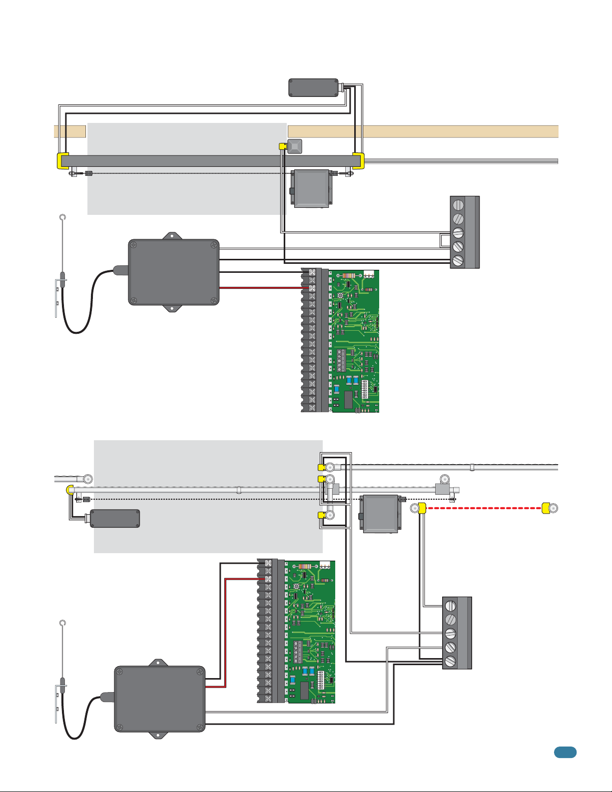
Wireless Reverse Edge Sample Setup - Single Receiver
Normally Open
ClosingDirection
Reversing
Edge
Antenna mounted
outside operator cover.
Coax Antenna Kit
P/N 1514-073
9 V battery operated transmitter mounted on gate.
Opening-Direction Reversing Edge (If filler post is used).
Closed Gate
24 VAC Receiver
Place receiver in operator.
Wireless Note: Refer to the
instruction sheet that comes
Com
24 Volt
Power is limited
to 250 mamps.
Terminal
with the receiver/transmitter
for more specific wiring and
mounting instructions.
Transmitter
Normally Open
Main
Edge
Common
Filler Post
(If necessary)
1
2
3
4
5
6
7
8
9
10
11
12
13
14
15
16
17
18
Normally Open
Filler Post Note: Install reversing edges on all
the gate support posts or filler post in this area
(e.g. cantilever gate installations, See below).
Opening-Direction Reversing Edge
Normally Open
Install Jumper Wire
EXIT
LOOP
4602
ON
NC
NO
SW1
Wall
5-Pin UL 325 Terminal Wiring
OPEN Entrapment Sensor
1
CLOSE Entrapment Sensor
2
OPEN Contact Sensor
3
CLOSE Contact Sensor
Common
When either direction reversing
edge gets obstructed, the gate will
STOP and reverse direction.
4
Low Voltage Common
5
Photo Sensor and Wireless Reverse Edge Sample Setup
ClosingDirection
Reversing
Edge
9 V battery operated
transmitter mounted on gate.
Antenna mounted
outside operator
cover.
Coax Antenna
Kit
P/N 1514-073
9150-065-S-9-11
Edge
Transmitter
Wireless Note: Refer to the
instruction sheet that comes
with the receiver/transmitter
for more specific wiring and
mounting instructions.
24 VAC Receiver
Place receiver in operator.
Install Opening-Direction
reverse edges on the gate
support post(s) in this area.
Com
24 Volt
Power is
limited to
250 mamps.
Main
Terminal
1
2
3
4
5
6
7
8
9
10
11
12
13
14
15
16
17
18
NC
NO
4602
EXIT
LOOP
ON
SW1
Normally Open
Cantilever Gate
Normally Open
Common
Common
Opening-Direction Photo Beam
Photo Sensor Power Note:
Normally Open
Photo sensors can be powered
by the built-in convenience
outlets located on the operator
(See page 27).
5-Pin UL 325 Terminal Wiring
Com
When a reversing edge gets obstructed, the
gate will STOP and reverse direction. When
a photo beam gets obstructed the gate will
STOP, then continue in the same direction
after obstructed photo beam has been
cleared until the gate cycle is complete.
OPEN Entrapment Sensor
1
CLOSE Entrapment Sensor
2
OPEN Contact Sensor
3
CLOSE Contact Sensor
4
Low Voltage Common
5
29
Page 32

4.3 Loop Detector Wiring
To help protect the operator from accidentally closing on vehicles in the gate’s path, DoorKing highly recommends that loops
and loop detectors be installed. Loops are laid underneath, cut into asphalt or concrete driveways or buried beneath gravel and
earth driveways. A loop detection system will sense a vehicle like a metal detector and send a signal to the gate operator
preventing the gate from automatically opening or closing on a vehicle when it is in the gate’s path. DoorKing recommends that
a licensed installer perform this work.
Reverse Loops
Reverse loops are placed on each
side of the gate to prevent the gate from
closing on a vehicle in the gate’s path. They will
reverse OR stop the cycling of the gate while a
vehicle is in or near the gate’s pathway.
DoorKing offers a free “Loop and
Loop-Detectors Information
Manual” PDF located at
Doorking’s web site for more
information. www.dkaccess.com
PVC Conduit
A
ON
1 2 345678
Reverse loop
lead-in wires are
twisted approx.
Note: See page 24,
SW 2, switch 2 for
reverse loop
options.
6 twists per foot
and are wired in
LOOP 1
series.
SW 2
Automatic Exit Loop
Automatically opens the gate for exiting vehicles
without having to use a transmitter or keypad. The
exit loop can be placed a minimum of 4 feet away
from the reverse loop or far enough away from the
gate so the gate has started or completely opened
by the time you drive up to it (Free exit).
PVC Conduit
ON
1 2345678
SW 2
SW 2,
switch 1
must be
ON to fully
open gate
(Normal
function).
Partial Open
B
Exit loop lead-in
wires are twisted
approx. 6 twists
LOOP 1
per foot.
Note: The plug-in exit loop detector can
be wired to partially open gate 14-Ft. if
SW 2, switch 1 is turned OFF. A jumper
wire must be connected from terminal
#10 to terminal #5 (See next page for
more information).
Note: Loop detector wiring is shown for
DoorKing plug-in loop detector P/N 9410-010
(Single Channel) only. If other loop detectors
are used, refer to the installation instructions
supplied with those detectors for wiring and
separate power instructions.
1
2
3
4
5
6
7
8
9
10
11
12
13
14
15
16
17
18
4 Ft. min. to avoid
reverse loop interference.
Automatic Exit
Loop Lead In Wires
B
9410
EXIT
DOORKING
4602-010
1
2
3
4
5
LOOP
ON
KEY SWITCH
NC
NO
4 Ft. min. to avoid gate
movement interference.
4 Ft. min. to avoid gate
movement interference.
Reverse
Reverse
Loop Lead In Wires
DoorKing
Plug-in
A
Single Channel Single Channel
OPEN
TIMER
ON
SW1 SW2
REVERSE
SENSITIVITY
Loop Detectors
9410
REVERSE
LOOP
30
9150-065-S-9-11
Page 33

SECTION 5 - WIRING
• When gate is closed, this input will fully open
gate.
• When gate is open and auto close timer SW 1,
switch 2 is turned ON, input will re-set and hold
timer.
• When gate is open and auto close timer SW 1,
switch 2 is turned OFF, input will close gate.
• When gate is closing, input will reverse gate.
For long gate application. SW 2, switch 3
must be OFF. Same operation as #4
terminal above but will only open a closed
gate 14-Ft. or reverse a closing gate to the
14-Ft. open position.
• This input ONLY fuctions when gate is fully
opened or in the closing cycle.
• When gate is open: auto close timer SW 1,
switch 2 is turned ON, input will re-set and hold
timer.
• When gate is open: auto close timer SW 1,
switch 2 is turned OFF, input will prevent gate
from closing.
• When gate is closing: input will stop gate when
SW 2, switch 2 is ON.
• When gate is closing: input will reverse gate
when SW 2, switch 2 is OFF.
• lf SW 2, switch 1 is ON, the plug-in exit loop detector
(Single channel) will FULLY open the gate (Normal Setting).
Single operator use ONLY.
• lf SW 2, switch 1 is OFF, the normal exit loop port
function is bypassed and a jumper wire is needed to open
and close gate(s) for certain applications:
- Terminal #10 connected to terminal #5 will PARTIALLY open
plug-in exit loop detector (Single channel) for a single operator.
- Terminal #10 connected to terminal #4 will FULLY open
bi-parting gates. Dual operators ONLY using DoorKing’s
plug-in DUAL channel loop detector. (Page 34).
Operation of relay is dependent on
setting of SW 1, switches 4 and 5.
Relay contacts can be set for Normally
Open (NO) or Normally Closed (NC)
operation.
Contact rating is 1 amp
maximum at 24-volts DC.
NC
NO
ON
1 2 345678
SW 1
ON
123 45678
SW 2
ON
1 2 345678
SW 1
ON
1 2 345678
SW 2
ON
12345678
SW 1
5.1 Main Terminal Description
4
5
6
(DoorKing 3-Button station ONLY)
(DoorKing 3-Button station ONLY)
10
ON
1 2345678
SW 2
15
Low Voltage Common
Full Open
24 VAC - 250 mamp max.
Full Open
Partial Open
Standard Reverse or Stop
Not Used
3-Button Full Open
3-Button Close
Exit Loop Logic Output
(DoorKing Loop Detectors ONLY)
Alarm Reset
Entrapment Alarm
Gate Tracker - Busy
Gate Tracker - Data
Dry Relay Contact
Dry Relay Contact
LED Indicator Output
Low Voltage Common
1
2
3
4
5
6
7
8
9
10
11
12
13
14
15
16
17
Jumper Wire SW 2, switch 2 OFF (Dual Operators only)
Jumper Wire SW 2, switch 2 OFF (Exit Loop Partial Open)
18
KEY SWITCH
4602
NC
NO
Provides 24 VDC, 250 ma. maximum to power
LED. Operation of LED is dependent on setting of
SW 1, switches 4 and 5 (See page 23).
9150-065-S-9-11
12345678
SW 1
ON
17
31
Page 34

5.2 Control Wiring for Single/Primary Operator
Important: Controls must be far enough from the gate so that the user is prevented from coming in contact with the gate while
operating the controls. Outdoor or easily accessible controls should have a security feature to prevent unauthorized use.
Wiring opening device when using
“Manual Mode Operation” for
convenience open operator(s):
The opening device should be wired
to the 2340 circuit board when
using the convenience open
system to “manually open”
the gate(s) during a power
failure. This will allow normal
daily operation as well as AC
power failure operation. This
should ONLY be wired this
way when operating in the
manual mode with
convenience open operators
(See page 39 for more info).
Com
Fire Box
#2-Full Open
#4-Connected device fully opens gate.
#5-Connected device opens gate 14-feet.
3-Wire Radio Receiver
250 mamp.
WARNING
M
OVIN
S
E
G
R
IO
G
A
U
O
T
S
p
E
e
IN
r
a
CAN
a
te
n
J
d
ga
U
f
r
te
R
e
e
CA
o
Y
o
nl
f
D
y
O
pe
U
o
w
R
opl
n
SE
h
o
e
or
t
D
e
n
a
a
op
ga
l
EATH
l
nd
ow
t
e
e
r
ob
a
a
c
te
r
h
s
e
i
D
tr
a
l
ga
d
o
uc
i
r
s
t
e
e
no
t
n
i
.
i
n
o
pa
to
t
ns
s
s
th
i
gh
ta
p
.
l
n
w
a
t
y
d
hi
i
i
n
l
n
e
ga
ga
R
ga
e
te
te
te
a
d
a
p
i
s
owne
r
a
e
t
mov
a
h
or
r
i
’
n
s
wa
g
ma
.
l
k
n
t
h
u
r
a
oug
l
a
nd
h
s
a
fe
ty
i
n
s
tr
uc
t
i
o
ns
.
CO
N
FOR
AN
MS T
SI/U
L
O
3
CAN
CE
2
5
R
/CSA C22
TIF
IE
D
VEH
TO
.
2
I
N
CULAR
O
5
.
3
CL
3
2
8
2
47
ASS
GA
T
E OPERA
M
O
D
E
L
T
SERIAL
OR
H
P
VO
L
TS
AM
PS
M
AX G
P
H
A
A
SE
T
E LO
A
D
6
D
oor
0
H
Ki
z
ng,
I
nc
.
,
I
ngl
ew
ood,
CA
E
ERS
REV
LOOP
EN
IT
OP
EX
TIMER
LOOP
H
SWITC
Y
KE
ING
0
-01
DOORK
4602
1
2
E
S
ON
3
ITIVITY
REVER
4
ENS
S
5
ON
2
SW
W1
S
C
N
O
N
Relay -
#2 - Full Open.
#5 - Opens gate 14-feet.
Com
24 volt
max.
Relay N.O. - #2 - Full Open.
#5 - Opens gate 14-feet.
24 Volt - 250 mamp. max.
Relay Com
24 Volt Com
1
Full Open
2
3
Full Open
4
5
4-Wire
Receiver
KEY SWITCH
Partial Open
Telephone
Entry
Key Switch
Stand-Alone
Keypad
Stand-Alone
Card Reader
Note:
All stand-alone and
telephone entry
devices must use a
separate power
source.
Red Full Open
Green Close
White Com
3-Button Control Station DoorKing ONLY
“Optional” REVERSES GATE for
Closing Direction Photo Sensors
Functions ONLY during gate closing cycle.
SW 2, switch 2: After photo sensor beam
gets obstructed:
OFF Setting - REVERSES GATE.
ON Setting - Stops gate then continues
closing when gate is clear (Same function
as UL 325 terminal #2).
Note: The ON setting is used to help prevent tailgating
but the photo sensor should be wired to the UL 325
terminal #2 when the “stop gate” function is desired,
see page 28 for more information.
ON
1 2 345678
SW 2
6
7
8
9
10
11
12
13
14
15
16
17
18
Com
#5 Terminal Note (Single Operator Only):
Any opening device connected to terminal #5
will open the gate to the partial open 14-ft setting.
Secondary entrapment protection devices will also
open the gate to the partial open setting. If the
Inherent Reverse Sensor gets activated during the
close cycle, it will always fully open the gate.
NC
NO
123 45678
SW 2
4602
ON
SW 2,
switch 3
must be
OFF.
32
9150-065-S-9-11
Page 35

5.3 Auxiliary Device Wiring
Blue Alarm Reset Terminal
Red Alarm Output Terminal
White Common Terminal
Remote Alarm Reset Station
(DoorKing P/N 1404-080 Only)
MUST be mounted in the
line-of-sight of the gate operator.
1
2
3
4
5
6
7
8
9
10
11
12
13
14
KEY SWITCH
4602
Gate Tracker
(Quad Box Shown)
DoorKing Access Control System (Model 1833, 1835, 1837 or 1838)
tracker system can be connected.This system can keep track of gate
operator
cycle count, shorted inputs, loop detector problems, any forced entry
attempts, if the gate has struck anything during the open or close cycle,
power interruptions, etc.
For more detailed information refer to the Tracker Installation and Wiring
Manual, DoorKing P/N 2351-010.
Terminal #4 (Full open) or #5 (14-Ft. open) required only if the tracker
board will activate the gate operator. Refer to the manual 2351-065 for
detailed information.
9150-065-S-9-11
15
16
17
18
NC
NO
33
Page 36

5.4 Bi-Parting Gates Wiring - Dual Gate Operators
EY SWI
• Separate power source for
photo sensors (See page 27).
Fence
Opening Non-Contact Sensor
To Open Photo #1
24 Volt
250 mamp. max.
3-Wire Receiver
(Fully Opens Gates)
4-wire receiver wiring,
see page 31.
Jumper Wire
ON
1 2345678
When using Dual
Channel plug-in
loop detector.
Connect #4 to #10:
fully opens gates.
SW 2, switch 1
SW 2
must be OFF.
Yellow
Loop Detectors
Reverse
Loop
Reverse
Loop
Reverse loop lead-in
wires are wired in series.
Automatic
Exit Loop
Loop Lead-In Wires
Com
Relay
Purple
Brown
Primary
Operator
N.O.
Orange
Secondary Entrapment Protection Devices for Bi-Parting Gates
To Close Photo #2 To Close Photo #2
Opening Contact Sensor
Gate
To Open Edge #3
Jumper Wire
10
11
12
13
14
15
16
17
18
1
2
3
4
5
6
7
8
9
Closing Non-Contact Sensor
KEY SWITCH
Open Photo
Close Photo
Open Edge
Close Edge
Common
UL 325
Terminal
4602
Opening Contact Sensor
To Common #5
• Requires AC power to each operator.
• Both operator DIP-switches must to be set.
• Connect all control devices, auxiliary devices
and loops to the primary operator only.
EXIT
LOOP
Primary Operator
Red to Close Photo #2
1
2
3
4
5
Green to
primary
operator
NC
NO
chassis
ground.
ON
SW1
Gate
Green to
secondary
operator
chassis
ground.
Filler Post if necessary (See page 8 for more information).Filler Post if necessary (See page 8 for more information).
Secondary
Operator
Yellow
Purple
Brown
Orange
Fence
Opening Non-Contact Sensor
To Open Edge #3
To Close Photo #2
To Open Photo #1
1
2
3
KEY SWITCH
4
5
6
7
8
9
10
Open Photo
11
Close Photo
Open Edge
12
Close Edge
13
Common
14
UL 325
Terminal
15
16
17
18
NC
NO
4602
To Common #5
Secondary Operator
1
2
3
4
5
Red to Close Photo #2
Com
Blue
Gray
BlueGray
Interconnection Cable
Sold separately from DoorKing.
6 wires used (8 - 18 AWG wires total).
Dual Channel
9409
Convenience Open Note: The gray wire is needed when using the
convenience open in the manual mode (See page 40 for wiring
Plug into Primary Operator Exit Loop Port
34
information about “Wiring dual operators in manual mode”).
9150-065-S-9-11
Page 37

SECTION 6 - OPERATING INSTRUCTIONS
IMPORTANT SAFETY INSTRUCTIONS
WARNING - To reduce the risk of injury or death:
1. READ AND FOLLOW ALL INSTRUCTIONS.
2. Never let children operate or play with gate controls. Keep the remote control away from children.
3. Always keep people and objects away from gate. NO ONE SHOULD CROSS THE PATH OF THE MOVING GATE.
4. Test the operator monthly. The gate MUST reverse on contact with a rigid object or stop or reverse when an object
activates the non-contact sensors. After adjusting the force or the limit of travel, retest the gate operator. Failure to
adjust and retest the gate operator properly can increase the risk of injury or death.
5. Use the emergency release only when the gate is not moving and power has been shut-off.
6. KEEP GATES PROPERLY MAINTAINED. Read the owner's manual. Have a qualified service person make repairs to gate
hardware.
7. The entrance is for vehicles only. Pedestrians must use separate entrance.
8. SAVE THESE INSTRUCTIONS.
6.1 AC Power and Reset Switch
Unlock the power switch cover and open to access
the Main Power, and the operator Reset switch.
Important: The operator
WILL NOT lose its open
and close limit positions
after pressing the reset
button.
W
ARNING
M
O
V
S
I
N
ER
G
I
G
OU
A
O
T
S
per
E
IN
a
C
a
t
n
e
J
A
d
g
U
N
f
a
r
t
R
e
e
e
C
on
Y
of
A
O
l
D
y
pe
U
o
w
R
op
not
S
h
e
D
or
l
E
e
n
a
gat
a
op
l
EA
l
nd
o
e
w
e
r
o
a
T
a
c
b
t
r
h
e
H
s
e
ga
i
t
D
a
l
r
d
u
o
i
r
s
t
c
e
e
n
t
n
i
.
i
ot
n
o
p
t
n
a
o
s
s
t
s
i
h
gh
ta
pl
.
nd
w
a
t
y
hi
i
i
n
l
n
e
g
ga
R
ga
a
e
t
t
t
a
e
e
e
d
a
p
i
s
ow
r
a
e
t
m
a
h
n
o
or
e
v
r
i
’
n
s
w
g
m
a
.
l
k
a
nu
t
h
r
a
o
l
ug
a
n
h
d
s
a
fe
t
y
i
ns
t
r
uc
t
i
ons
.
C
O
N
FO
A
R
N
M
S
I/
S
U
TO
L-
325
C
C
A
ER
N
/
TI
C
FI
S
A
ED
C
V
22.
TO
E
H
2
I
N
C
O
U
5
.
3
C
3
L
247
8
LA
A
2
R
S
S
G
AT
E
M
O
O
D
P
EL
E
R
A
T
S
O
ER
H
R
P
I
A
L
V
OL
TS
A
M
P
S
60
M
A
P
X
HA
G
A
S
TE
E
LO
A
D
D
o
o
H
r
K
z
i
n
g
,
In
c
.
,
In
g
l
e
w
o
o
d
,
C
A
DC
POWER
OFF
RESET
AC
POWER
OFF
Reset Button - Used to turn off the
entrapment alarm and to reset the
operator after a HARD shutdown
has occurred.
Alarm Siren
AC Power Switch - Powers the
operator ON (toggle up) or
OFF (toggle down).
DC Power Switch - Turns the DC
system power ON (toggle up) or
OFF (toggle down).
This switch is only installed on
model 9150 operators with the DC
convenience open system installed.
9150-065-S-9-11
Every time the 9150 is powered up, the First open command will automatically run “Multiple
gate cycles” that will locate and remember the gate’s open and close positions (See page 25).
35
Page 38

6.2 Shutdown Conditions
Under various entrapment conditions the operator will assume either a soft or hard (alarm) shutdown. To determine what
type of reset action is required, you will need to understand how the different entrapment conditions affect the gate
operator.
Soft Shutdown
This occurs in various situations where the inherent or secondary entrapment protection devices have been activated.
In a soft shutdown condition, the operator will not respond to any input that was present when the entrapment
protection device sensed an obstruction. If the gate stops at the open position, the operator will not respond to the
automatic close timer.
• Example 1 - A time clock keys the gate open in the morning and an entrapment protection device senses
an obstruction prior to the gate reaching the full open position. If the entrapment is sensed by the inherent
system, the gate will reverse and run back to the closed position. The time clock input is still present, but
the gate will not re-open.
Note: In some systems, the time clock input comes from the telephone entry system relay. This same relay may also
provide open commands for a card reader, MicroPLUS transmitters and the visitor telephone entry. If so, these devices
will also be disabled in a soft shutdown condition.
• Example 2 - If the gate is closing and an entrapment protection device is activated, the gate will either stop
or reverse and run back to the open position, depending upon if the secondary or inherent device was
activated. The automatic close timer will not close the gate.
• Example 3 - Vehicle arrives at exit loop and gate runs towards the open position. If the inherent entrapment
protection gets activated during this opening cycle, the gate reverses and runs back to the closed position.
After the inherent entrapment protection is cleared, If the vehicle is still present at the exit loop, a soft
shutdown condition does not occur. The exit loop input provides an immediate reset of the operator and the
gate will again run to the open position.
Resetting a Soft Shutdown
In some conditions, a soft shutdown will reset as soon as the entrapment condition clears. For example, if a
non-contact sensor (photo cell) is sensing an obstruction, the operator will stop the gate and assume a soft
shutdown condition. When the photocell clears, the operator will return to normal operation.
When the operator is in a soft shutdown, activation of any "intended input" will reset the operator. An "intended
input" includes any command, any standard safety input and any loop input. Activating any of these inputs will reset
the gate. At that point the gate will return to normal operation. If the gate is open, the automatic close timer will
then time out and close the gate.
Hard Shutdown (Alarm Activated)
A hard shutdown condition occurs when: (1.) The inherent entrapment protection system (Type A) gets activated
TWO consecutive times before the gate completes the open or close cycle. (2.) The reversing edge (Type B2) gets
activated and reverses but before the gate completes the reverse cycle the inherent entrapment protection system
(Type A) gets activated.
• Example of a Hard Shutdown - The gate is closing and the inherent entrapment protection system senses
an obstruction and causes the gate to reverse direction. As the gate begins to run in the open direction, a
second obstruction is sensed prior to the gate reaching the full open position. Once the second obstruction
has been sensed, the operator will stop, the audio alarm will sound and all standard inputs are shut
down (including open commands, safety commands, loop inputs, etc.).
– To silence the alarm, press the reset button or after 5 minutes, the audio alarm will shut off but will
“chirp” every 5 seconds. This indicates that the operator is in a hard shutdown condition (The reset
button must be pressed to reset the operator and stop the alarm “chirping”).
36
9150-065-S-9-11
Page 39

Resetting a Hard Shutdown
The operator is in a hard shutdown condition when the audio alarm is sounding OR “chirping” every 5 seconds.
• Before resetting a hard shutdown, determine why the shutdown occurred. Inspect the gate for any
obstructions along its path that could have activated the inherent entrapment sensing system. Inspect
the gate and gate hardware.
The audio alarm will sound for five minutes, or until the operator’s reset button is pushed. After (5) five minutes the
alarm will “chirp every 5 sec.” and the hard shutdown condition will remain in affect until the reset button is pushed.
Note: DoorKing operators have a built-in alarm reset push button mounted on the operator above the power ON-OFF
toggle switch. Activating this button will return the gate operator to normal operation, but will not cycle the gate
operator. A remote alarm/reset station (P/N 1404-080) can be mounted external of the gate operator provided that it
is installed in the line-of-sight of the gate and gate operator.
The gate operator WILL NOT lose its open and close positions after resetting a hard shutdown.
Once the gate has been reset, an open or close command is needed to start the gate operator. Most activating
commands will cause the gate operator to cycle to the open position. This includes activation of a key switch or
open command and activation of an automatic exit loop. Activation of a close command will run the gate to the
closed position.
6.3 Manual Gate Operation
This operator is equipped with one of two types of manual release systems, “Fail-Safe” (required by many city codes) or
“Fail-Secure” that will allow the gate to be pushed open in the event of a power outage or equipment failure.
Caution: Never attempt to manually push open any gate with an operator attached to it until you
have verified that power to the operator has been shut-off.
Fail-Safe Manual Release System (Factory Installed)
This manual release system is the most reliable and safest method for placing the gate operator in manual
operation. It is the preferred method of emergency gate operation under worse case conditions by many Fire Chiefs
and Building Inspectors and is typically used in Class I and Class II applications. This system is accessible from
either side of the gate and requires NO keys, cranks or other tools to manually operate the gate. This prevents any
delays for emergency vehicle access in the event of a power outage. The operator “Fails” (Loss of AC power) in a
“Safe” (Manually operable) condition.
Solenoid Lock
Clutch Plate
SW 2, switch 4
must be OFF.
ON
12 3 4 5 6 7 8
SW 2
Solenoid lock does NOT secure the clutch plate during an
AC power failure or turning AC power off. Gate can be
immediately manually operated during these conditions.
9150-065-S-9-11
Solenoid lock WILL retract and secure the clutch plate during
normal operation ONLY if operator senses an unauthorized
manual open attempt. Gate will NOT be allowed to move.
37
Page 40

Fail-Secure Manual Release System (Owner Installed)
This manual release system (Installed 2600-865 Fail-Secure Manual Release Kit) allows the gate to be manually
operated ONLY after unlocking the gate operator. Power outages or turning power off WILL NOT allow gate to be
manually operated without physically unlocking the gate operator with the key first. This option is typically used in Class
III and Class IV applications. The gate operator “Fails” (Loss of AC power) in a “Secure” (Manually in-operable) condition.
SW 2, switch 4 must be ON.
Important: solenoid lock
MUST be in position shown.
12 3 4 5 6 7 8
SW 2
ON
Solenoid
Lock
Solenoid lock does NOT allow the clutch plate to rotate when:
• The AC power is on but the operator is not cycling.
Clutch Plate
Solenoid lock automatically retracts and allows clutch
plate to rotate ONLY during normal gate cycling.
• The AC power is turned off.
• AC power failure.
Key Release
Turning key 1/2 turn
retracts solenoid lock
and allows clutch plate
to rotate for manual
W
ARNI
NG
M
O
VI
S
NG
E
R
I
G
O
AT
U
O
S
per
E
I
N
a
CAN
and
t
e
J
gat
U
f
r
R
e
e
e
CAU
o
Y
of
nl
D
y
O
peopl
o
w
R
not
SE
hen
or
D
e
a
a
ope
gat
l
EA
l
nd
ow
e
r
obst
a
TH
a
c
t
r
hi
e
ea
D
l
ga
ruct
dr
o
i
s
t
e
e
not
n
i
.
i
n
ons.
p
t
a
o
s
s
t
i
h
ght
t
pl
a
nd
w
a
y
h
i
i
i
n
l
n
e
gat
gat
R
ga
e
t
ad
e
e
e
a
pa
i
s
ow
r
e
t
m
a
h
ner
ovi
or
’
ng.
s
w
m
al
k
anua
t
hr
ough
l
a
nd
s
a
f
e
t
y
i
nst
r
uct
i
ons.
C
O
N
F
O
A
R
N
MS
S
I
/
U
T
L
O
3
C
C
2
A
E
5
N
R
/
T
C
I
F
S
I
A
E
D
C
V
2
T
2
E
O
.
H
2
IC
N
O
U
5
.
3
C
3
L
2
8
L
A
2
4
A
7
R
S
S
G
AT
E
M
O
O
D
P
E
E
L
R
AT
S
O
E
H
R
R
P
I
A
L
V
O
L
T
S
A
MP
S
M
A
P
X
HAS
G
A
T
E
E
L
O
A
D
6
D
o
0
o
H
r
Ki
z
n
g
,
I
n
c
.
,
I
n
g
l
e
w
o
o
d
,
CA
operation with or
without AC power.
Operator
Housing
Clutch Plate
Emergency Vehicle Access Conditions
This automatic vehicular gate system is designed to allow access to emergency vehicles under different operating conditions.
1. During normal AC powered operation, emergency vehicles access the gate by a separate emergency access
device individually installed and wired to your gate system. The type of devices that can be used in your community depends on your city codes. These devices may include (but are not limited to) Fire Department lock boxes,
Click-2-Enter radio receivers, strobe light sensors, siren sensors, etc.
2. In the event of an AC power failure, the emergency vehicle access device will not function because the gate
operator is un-powered. “Fail-Safe” or “Fail-Secure” release systems for the 9150 allow the gate to be manually
operated during AC power failure. ONLY the “Fail-Safe” release system allows the gate to be manually operated
without unlocking the operator first and has been designed that way to allow emergency personnel to immediately
manually operate the gate from either side under emergency situations.
38
9150-065-S-9-11
Page 41

SECTION 7 - OPTIONAL CONVENIENCE OPEN ADJUSTMENTS
The optional convenience open system installed in your vehicular gate operator is designed as a convenience enhancement only.
It is not designed or intended to provide continuous gate operation during a power outage. Its sole purpose is to provide a
method to open the vehicular gate to allow unimpeded traffic flow when the gate and access control system is without power. If
your access control system requires 100% power backup and continuous operation when primary (AC) power has failed, a
power inverter / backup system, such as DoorKing’s Model 2000, is required.
• The convenience open system cannot provide continuous gate operation during a power outage.
•
The gate will cycle (Manual or Automatic Mode) to the open position ONE TIME ONLY after AC power failure.
• The convenience open system requires testing on a monthly basis to insure the batteries are fully charged and that the
system is operational.
• The convenience open system uses two 12-volt, 3.0 amp-hour gel-cell batteries. These batteries should be replaced
every two years on average, or sooner if required.
• Batteries are affected by temperature. Cold temperatures will reduce the effectiveness of the batteries. High temperatures
will result in a shortened battery life.
• Batteries are not covered under warranty.
7.1 Circuit Board (2340) Setup
Manual Mode Device Connection
See next page for specific dual operator wiring.
Push
Stand-Alone Radio Receiver
This radio receiver will work during
normal daily operation as well as
during a power outage. The radio
receiver will be powered from the
operator’s batteries during a power
outage.
Com
Relay
24 Volt
10987654321
2340 Board Terminal
DIP-Switches
8
7654321
2340
ON
Button
Dry Contact
Emergency
Vehicle Access
Dry Contact
DC Timer
Automatic Mode after loss of AC Power, Switch 1 ON.
The Convenience Open system will automatically
open the gate approximately 3 seconds after loss
of AC power. The DC timer will run the DC motor.
NO devices need to be connected to the 2340
board. Automatic mode is always used for gates in general access
applications such as gated communities, apartment complexes, etc.
12345678
ON
Manual Mode after loss of AC Power, Switch 1 OFF,
Residential Use ONLY.
The system will NOT automatically open the gate
after loss of AC power. A manual input is needed
(Remote, push button or a key switch) to open
the gate from one of the “Manual Mode Devices”
physically wired to the 2340 circuit board (The DC timer will run the DC
motor). Any control devices wired to the 4602 main terminal will NOT
function after loss of AC power.
Note: If the gate operator is controlled by a DoorKing access controller
(Models 1833, 1835, 1837 or 1838), the “Manual Mode” will NOT function
during a power outage.
12345678
ON
Restart Options once AC Power is restored,
Switch 3 ON or OFF.
Once AC power is restored, the system’s control
board can be set to “automatically re-key” the
gate operator (switch 3 ON) to establish normal
operation, or can be set to require a “manual input” from the 2340 OR
4602 circuit board (switch 3 OFF) before the operator resumes normal
operation.
12345678
ON
DC Timer: MUST be adjusted so the gate stops approximately six inches from the full open position. Clockwise increases
the DC motor run time, counter-clockwise decreases the run time. Do not allow the DC motor to run long enough to hit the
gate stop and continue to run. The operator clutch will slip and stall the DC motor. The circuit board may get damaged!
9150-065-S-9-11
39
Page 42

7.2 DC System Description
Green to 4602 Main Terminal #4
Purple to 4602 Main Terminal #3
White to 4602 Main Terminal #18
Gate will automatically OR be manually OPENED and
STAY open during an AC power failure. DIP-Switch 3
setting will determine how operator will return to
normal operation once AC power has been restored.
Red/White
DC
ON/OFF
Power
Switch
DC Motor
DC Motor Negative Output
DC Motor Positive Output
Battery Negative Input
10 9 8 7 6 5 4 3 2 1
Black/White
2340 Board Terminal
Red/White
12 V
3 Amp/Hr
Battery
12 V
3 Amp/Hr
Battery
Batteries
DIP-Switches
8 7 6 5 4 3 2 1
2340
Charging LED
Do Not Adjust DC Timer needs
7.3 DIP-Switch Settings
See
previous
page.
Battery Positive Input
24 VAC Common
24 VAC Input
Activation Output
ON
to be adjusted.
Radio Power
Open Input
Common
DC Timer
Do Not
Adjust
Wiring DUAL operators
in Manual Mode.
If the operators will be in Manual
mode (Switch 1 OFF) to OPEN the
gates after an AC power failure,
connect terminal #2 on each of
the 2340 boards together.
Primary Operator
2340 Board Terminal
10 9 8 7 6 5 4 3 2 1
Gray
Secondary Operator
2340 Board Terminal
10 9 8 7 6 5 4 3 2 1
This wiring will NOT affect the
Auto mode function if the
operators are switched from
Manual mode (Switch 1 OFF) to
Auto mode (Switch 1 ON) in the
future.
Interconnection Cable Wire
Switch Function Setting Description
Manual input from 2340 board needed to open gate when a power outage occurs.
1
Power Failure
Operating Modes
Opening Direction. Setting must be the same as SW 1, switch 1 on the 4602 circuit board.
Front
Opening
direction
2
using ON
setting.
Mount
Restored
3
AC Power
Operator
Response
4
5-8
40
Operator Type
Not Used
OFF
ON
Opening
direction
using OFF
setting.
OFF
ON
OFF
OFF
Gate will automatically open when a power outage occurs.
Opening
direction
using OFF
setting.
Center or
Post
Mounts
Opening
direction
using ON
setting.
When AC power is restored, a manual input (push button, loop, radio receiver, etc.)
is required to return the gate to normal operation from 2340 or 4602 board.
When AC power is restored, a 1-second pulse is sent to the gate operator input to
automatically restore normal operation.
Must be in the OFF position for the 9150.
Must be in the OFF position.
Opens
with
OFF
setting.
All Rear
Mounts
Left
All Rear
Mounts
Right
Opens
with
ON
setting.
9150-065-S-9-11
Page 43

SECTION 8 - MAINTENANCE AND TROUBLESHOOTING
Inspection and service of this gate operator by a qualified technician should be performed anytime a malfunction is observed or
suspected. High cycle usage may require more frequent service checks.
DO NOT
remove clutch
8.1 Maintenance
plate.
When servicing the gate operator, always check any secondary
(external) reversing devices (loops, photocells, etc.) for proper
operation. If external reversing devices cannot be made operable,
do not place this operator in service until the malfunction can be
identified and corrected.
Always check the inherent reversing system when performing any
maintenance. If the inherent reversing system cannot be made
operable, remove this operator from service until the cause of the
malfunction is identified and corrected. Keeping this operator in
service when the inherent reversing system is malfunctioning
creates a hazard for persons which can result in serious injury or
death should they become entrapped in the gate.
When servicing this gate operator, always turn power OFF!!
Operator
Component
Alarm
Batteries
DC Open System
Drive Belt
Chain
Clutch
Fire Dept.
Gate
Grease
Loop(s)
Primary Reverse System
Pulleys
Release
Secondary Reverse Device
Complete System
Activate the primary (inherent) reverse system by blocking the
gate with a solid object. When the gate reverses, block the gate
in the opposite direction prior to the limit being reached. The
entrapment alarm should activate. Press the reset button to
silence the alarm.
If operator is equipped with optional DC open system, check the
batteries for any leakage or loose connections. Batteries should
be replaced every two years.
If operator is equipped with optional DC open system, check to
be sure the system opens the gate upon loss of AC power.
Check for alignment, tightness and wear.
Check for sagging. Tighten if necessary.
Check for proper slippage when an obstruction is encountered.
Check emergency vehicle access device for proper operation.
Inspect for damage. Check gate wheels. rollers and guides for
wear and grease if necessary.
Wheels and guide rollers if necessary.
Check vehicular exit and reverse loops for proper operation.
Check that the gate reverses on contact with an object in both
the opening and closing cycles.
Adjust the reversing sensor and/or clutch if necessary.
Check for alignment. Check setscrews.
Check manual release for proper operation.
Check secondary (external) reverse device(s) stop or reverse the
gate when activated.
Complete check of gate and gate operating system.
Maintenance
Align clutch plate
holes with screws to
repair solenoid lock.
Every time the 9150 is powered up, the First open
command will automatically run “Multiple gate
cycles” that will locate and remember the gate’s
open and close positions (See page 25).
Remove
Pulley Assembly
Monthly Interval
6 3 12
✓
✓
✓
✓
✓
✓
✓
✓
✓
✓
✓
✓
✓
✓
✓
9150-065-S-9-11
41
Page 44

8.2 Troubleshooting
Have a good VOM meter to check voltages and continuity. A Meg-Ohm meter capable of checking up to 500 meg-ohms of
resistance is necessary to properly check the integrity of the ground loops. When a malfunction occurs, isolate the problem to
one of three areas: 1. the operator, 2. the loop system, 3. the keying devices. Use caution when checking high voltage
terminals, motor capacitor and the motor.
1. Check the input indicator LEDs. They should only come ON when a keying device (card reader, push button, etc.) is activated.
If any of the input LEDs are ON continuously, this will cause the gate operator to hold open. Disconnect the keying devices one
at a time until the LED goes OFF.
2. Check any external secondary entrapment protection devices. Any short or malfunction in these devices can cause the gate
operator to stop or to hold open.
3. A malfunction in a loop or loop detector can cause the gate operator to hold open, or to not detect a vehicle when it is
present over the loop. Pull the loop detector circuit boards from the loop ports on the operator circuit board. If the malfunction
persists, the problem is not with the loop system. For more information on trouble shooting loops and loop detectors, refer to
your loop detector instruction sheet and to the DoorKing Loop and Loop Detector Information Manual.
4. Check to be sure that there are no shorted or open control wires from the keying devices to the gate operator. If a keying
device fails to open the gate, press the Key Switch or momentarily jumper across terminals 4 and 18 on the operator circuit
board. If the gate operator starts, this indicates that a problem exist with the keying device and is not with the gate operator.
5. If a three-button control station (open-close-stop) is connected to this gate operator, check for proper wiring. Only a
DoorKing three button control station (P/N 1200-006 or 007) can be used with this gate operator. Others will cause a
malfunction.
6. Check the high voltage supply. A voltage drop on the supply line (usually caused by using too small supply voltage wires) will
cause the operator to malfunction. Refer to the wire size chart in section 2.1 on page 20.
Every time the 9150 is powered up, the First open command will automatically run “Multiple
gate cycles” that will locate and remember the gate’s open and close positions (See page 25).
Symptom Possible Solution(s)
Operator will
not run. Power
LED is OFF.
Operator will
not run. Power
LED is ON.
• Check that AC power to the operator is turned ON.
• Transformer may be overheated. Turn power off and allow board to cool for several minutes then
retest. Check for low 115 VAC power and low voltage shorts.
• Check for 115 VAC at high voltage terminal. If voltage measures 0, check the incoming power wires
or replace the circuit board.
• If a photo-cell is used as a secondary entrapment prevention device, check to be sure that the beam
is not blocked.
• Be sure that the chain is not too tight. A too tight chain may cause the operator to stall.
• Bypass circuit board and Check Motor:
Turn power switch OFF and remove the circuit board. Place a jumper wire from the 117 VAC
SWITCHED terminal to the BLUE wire on the 8 pin POWER connector on the control board.
CAUTION – HIGH VOLTAGE. Turn the power switch on. The motor should run. Turn the power
switch OFF and remove the jumper.
With power still OFF, place a jumper wire from the 117 VAC SWITCHED terminal to the RED wire on
the 8 pin POWER connector on the control board. CAUTION – HIGH VOLTAGE. Turn the power
switch on. The motor should run in the opposite direction. Turn the power switch off and remove
the jumper.
• If the motor runs in both steps above, replace the control board. If the motor does not run, or runs
in only one direction, problem can be a bad motor, motor capacitor, motor resistors, wire
connections from the control board to the motor or a bad control board.
42
9150-065-S-9-11
Page 45

Symptom Possible Solution(s)
Gate opens a short
distance, then stops
and reverses.
Gate opens but
will not close.
Gate closes but
will not open.
• Check that the clutch is adjusted properly and is not slipping.
• Disconnect the gate from the gate operator and check that the gate slides freely without any binding.
• Re-adjust the reverse sensitivity.
• Check that the magnetic pickup transistors on control board are not obstructed by excess wires.
Electrical interference from excess wires can diminish magnetic field.
• Check that the magnetic pickup transistors on control board are within 1/8 inch of the clear plastic
protective cover above the black plastic magnetic spring assembly on the main shaft.
• Contunue troubleshooting or replace the circuit board.
• Check the input LEDs. Any ON will hold the gate open and indicates a problem with a keying device.
• Check the secondary safety devices. Any activated will hold the gate open and indicates a problem
with the safety device.
• Check the loop detectors. Any activated can hold the gate open and indicates a problem with the
loop detector or ground loop.
• Operator may be in a “soft shutdown.” Activate any keying device to determine if operator returns
to normal operation.
• If automatic close is desired, be sure SW 1, switch 2 is ON and set timer open from 1-23 seconds.
• Bypass circuit board and check motor as described on previous page.
• Operator may be in a “soft shutdown.” Check input LEDs. If any are ON, momentarily disconnect,
then re-connect the wire going to the respective terminal. Operator should open.
• Check to be sure that the operator is running in the proper direction. Turn power OFF, and then back
ON. Activate a keying device. Operator should run in the open direction. If operator runs in the
close direction, turn power OFF and change direction switch SW 1, switch 1. Go to above section if
operator now opens but will not close.
• Be sure that the each LED on the control board lights when the keying device connected to the
that terminal is activated. If LED does not light, momentarily place a jumper wire from terminal 1 to
the input terminal being checked. If LED lights and gate opens, problem is with the keying device. If
LED does not light, replace control board.
• Bypass circuit board and check motor as described on previous page.
Gate starts to close,
then reverses to
open.
Gate closes then
re-opens.
Alarm is sounding.
Operator will not
run.
Alarm chirps once
every 5 seconds.
Operator will not
run.
• Check that the clutch is adjusted properly and is not slipping.
• Re-adjust the reverse sensitivity.
• Disconnect the gate from the gate operator and check that the gate slides freely without any binding.
• Check the loop detector LEDs and input LEDs. Any that flash ON will cause the gate to reverse.
• Check the Magnetic Sensor LEDs on the circuit board. If either LED is not blinking as the operator is
running, check that the magnetic pickup transistors are within 1/8 inch of the protective plastic
cover above the magnet assembly on the main shaft.
• Contunue troubleshooting or replace the circuit board.
• Check for any input or loop detector LED’s that are ON.
• Check that the operator is running in the proper direction (see “gate closes but will not open”).
• Check the SELF-TEST DIP switch setting, SW 1, switch 6 should be OFF.
• Operator is in a “hard shutdown” condition. Reset button must be pushed to return operator to
normal operation, see Section 6.2 Shutdown Conditions, pages 36-37.
• Operator has been in a “hard shutdown” condition in excess of 5 minutes. Reset button must be
pushed to return operator to normal operation, see Section 6.2 Shutdown Conditions, pages 36-37.
9150-065-S-9-11
43
Page 46

8.3 Accessory Items
The following accessory items are available for the model 9150 slide gate operator.
Contact Sensors - For use as a secondary entrapment protection device. Miller Edge, Inc., MGO20, MGR20, MGS20
Photo Cell - Non-contact (photocell) sensors for use as a secondary entrapment protection device.
MMTC, Inc. Model IR55 - P/N 8080-010 MMTC, Inc. Model 60-278 - P/N 8080-011
Carlo Gavazzi Type PMP12 - P/N 8080-030 Carlo Gavazzi Type PMT - P/N 8080-031
Loop Detector - Detectors plug directly into ports on circuit board simplifying wiring.
Single channel detector - P/N 9410-010 Dual channel detector - P/N 9409-010
Loop Wire - 18 AWG loop wire with XLPE insulation is ideal for ground loops. Available in 500 and 1000 foot rolls. Red, blue or
black insulation.
Pre-Fab Loops - Prefabricated ground loops. 24-foot circumference with 50-foot lead-in. Available in yellow, red or blue jackets.
Not for use in asphalt roadways.
Loop Test Meter - Meg-ohm meter checks the integrity of ground loops. P/N 9401-045
Remote Alarm/Reset Station - Provides a remote station to reset an operator in a hard shutdown condition. Must be mounted
in line-of-site of the gate and operator. Includes visual alarm light and audible siren. P/N 1404-080.
3-Button Control Station - Provides open-close-stop manual operation of the gate.
Stand Alone Box - P/N 1200-006 Interior (fits in single gang box) - P/N 1200-007
Interconnect Cable - Interconnect wire cable contains all the necessary wires to interconnect primary / secondary operators.
Cable length: 30 ft. - P/N 2600-755 40 ft. - P/N 2600-756 50 ft. - P/N 2600-757
Time Clock - 7 day and 365 day time clocks can be used to automatically open gate at pre-set time and days. Compact clock fits
inside the operator. 7 day clock - P/N 2600-791 365 day clock - P/N 2600-795
V-Wheels - 4 inch and 6 inch. UHMW or Steel. Roller bearings or sleeve bearings. Single or tandem wheel configurations.
Endless Idler Assembly with Protective Cover - Use when gate operator chain needs 180° return. P/N 2600-818
Guide Rollers with Protective Covers - A variety of sizes to support slide gates.
Gate End Retainer - Fits on top of end post and helps stabilize the end of the gate in the open or closed position (End post NOT
provided). P/N 1204-004
Base Plate for 9150 - Required for post mount installation. P/N 2600-495 (6 x 6 steel posts NOT provided).
Base Plate Stop Brackets for 9150 - Required for post mount installation when using chain stops. P/N 2600-970
Additional #40 Chain - 20 ft. per box. P/N 2600-442
9150 Fail-Secure Manual Release Kit - Changes the Fail-Safe manual release to a Fail-Secure manual release. P/N 2600-865
Heater with Fan Assembly Kit - Thermostatically controlled heater and fan for cold and hot environments. P/N 1601-154
Surge Devices - High and low voltage surge suppressors help prevent circuit board failure caused by lightning strikes and
power surges. High Voltage - P/N 1876-010 Low Voltage - P/N 1878-010
Gate Scale - Use to test torque required to move gate. P/N 2600-225
Speed Bumps - Prefabricated six-foot speed bump reduces traffic speed through gate system. P/N 1610-150
44
9150-065-S-9-11
Page 47

Model 9150 1/2 HP 115 VAC
Blue
Motor
Resistors
1 Ohm
1 Ohm
30 Watt
30 Watt
Red
50uf Capacitor
Blue
Red
1/2 HP
Motor
Ground
Built-In
Solenoid Lock
Alarm
Red
White
White
Yellow
Reset
1
2
3
4
5
6
7
8
9
10
Yellow
11
Red
12
13
14
15
16
17
White
18
Black
AC Power
KEY SWITCH
DOORKING
4602-010
1
2
3
4
5
NC
NO
EXIT
LOOP
ON
ON
SW1 SW2
MOV Assembly
Chassis
Ground
115 VAC
Black
OPEN
TIMER
White
Neu Hot
Hot Neu
White White
Neutral
Hot
Black
Power
Convenience Outlets
REVERSE
LOOP
Green
Blue
Red
White
Black
Blue
Red
Brown
REVERSE
SENSITIVITY
Board
Ground
Green
White
Brown
9150-065-S-9-11
45
Page 48

Model 9150 1/2 HP 115 VAC / Convenience Open
50uf Capacitor
Blue
Motor
Resistors
1 Ohm
Blue
30 Watt
1 Ohm
30 Watt
Red
Red
Solenoid Lock
1/2 HP
Motor
Ground
Built-In
Alarm
Red
Green
Purple
White
Yellow
DC Power
White
White
Reset
1
2
Purple
3
Green
4
5
6
7
8
9
10
Yellow
11
Red
12
13
14
15
16
17
White
18
Black
AC Power
KEY SWITCH
DOORKING
4602-010
1
2
3
4
5
NC
NO
EXIT
LOOP
ON
ON
SW1 SW2
MOV Assembly
Chassis
Ground
115 VAC
Black
Red/White
Red/White
OPEN
TIMER
White
Neu Hot
Hot Neu
White White
Hot
Black
Neutral
Power
Convenience Outlets
REVERSE
LOOP
Green
Blue
Red
White
Black
Blue
Red
Brown
REVERSE
SENSITIVITY
Red/White
Board
Ground
Green
White
Green
Purple
2340
Red
Black
White
Brown
DC Motor
DC Motor
Batteries
12 V
3 Amp/Hr
Battery
Red/White
Black/White
12 V
3 Amp/Hr
Battery
46
9150-065-S-9-11
Page 49

Model 9150 1/2 HP 208 / 230 / 460 VAC
Alarm
208 VAC
To AC
Power
Switch
To AC
Power
Switch
To AC
Power
Switch
To AC
Power
Switch
230 VAC
To AC
Power
Switch
To AC
Power
Switch
460 VAC
To AC Power Switch
Blue
Black
Brown
White
Black/White
Blue
Black
Brown
White
Black/White
Blue
Black
Brown
White
Black/White
208/230/460 VAC
Black/White
Light Blue
Maroon Red
Blue
Black
Brown
White
Chassis
Ground
Motor
Resistors
1 Ohm
Blue
1 Ohm
30 Watt
Step-Down
Green
Hot Hot Hot
Red
30 Watt
White
Transformer
Neu Neu
50uf Capacitor
Black
Blue
Red
White
White
1/2 HP
Motor
Ground
Built-In
Solenoid Lock
White
Brown
Red
White
White
Yellow
Reset
1
2
3
4
5
6
7
8
9
10
Yellow
11
Red
12
13
14
15
16
17
White
18
AC Power
KEY SWITCH
DOORKING
4602-010
1
2
3
4
5
NC
NO
EXIT
LOOP
ON
ON
SW1 SW2
OPEN
TIMER
White
Neutral
Convenience Outlets
REVERSE
LOOP
REVERSE
SENSITIVITY
Power
Green
Blue
Red
White
Black
Blue
Red
Brown
Black
White
Board
Ground
Green
9150-065-S-9-11
47
Page 50

Model 9150 1/2 HP 208 / 230 / 460 VAC / Convenience Open
Alarm
Red
Green
Purple
208 VAC
230 VAC
460 VAC
To AC Power Switch
White
Yellow
DC Power
White
White
To AC
Power
Switch
To AC
Power
Switch
To AC
Power
Switch
To AC
Power
Switch
To AC
Power
Switch
To AC
Power
Switch
Reset
1
2
Purple
3
Green
4
5
6
7
8
9
10
Yellow
11
Red
12
13
14
15
16
17
White
18
AC Power
KEY SWITCH
DOORKING
4602-010
1
2
3
4
5
NC
NO
Blue
Black
Brown
White
Black/White
Blue
Black
Brown
White
Black/White
Blue
Black
Brown
White
Black/White
208/230/460 VAC
EXIT
LOOP
ON
SW1 SW2
Light Blue
ON
Blue
Black
Brown
White
Black/White
Chassis
Ground
Maroon Red
Red/White
Red/White
OPEN
TIMER
Motor
Resistors
1 Ohm
Blue
1 Ohm
30 Watt
Step-Down
Green
Hot Hot Hot
Red
30 Watt
Black
White
Transformer
Neu Neu
White
Neutral
Convenience Outlets
REVERSE
LOOP
REVERSE
SENSITIVITY
50uf Capacitor
Blue
Red
White
White
Black
White
Power
Green
Blue
Red
White
Black
Blue
Red
Brown
Red/White
Board
Ground
Green
White
Green
Purple
2340
1/2 HP
Motor
Built-In
Solenoid Lock
White
Brown
DC Motor
DC Motor
Red
Black
Batteries
12 V
3 Amp/Hr
Battery
Red/White
Black/White
Ground
12 V
3 Amp/Hr
Battery
48
9150-065-S-9-11
Page 51

Model 9150 1 HP 115 VAC
Orange
1 Ohm
30 Watt
Orange
1 Ohm
30 Watt
Yellow
Motor
Resistors
Blue
1 Ohm
1 Ohm
Red
1 HP Motor
Alarm
Red
White
Yellow
Reset
Black
MOV Assembly
Chassis
Ground
115 VAC
Black
65 Watt
Orange
Black
Red
65 Watt
Yellow
White
Neu Hot
Hot Neu
White White
Neutral
Blue
Hot
Power
Ground
Built-In
Solenoid Lock
White
Brown
White
9150-065-S-9-11
AC Power
Convenience Outlets
1
2
3
KEY SWITCH
4
5
EXIT
LOOP
OPEN
TIMER
6
7
8
Yellow
Red
White
DOORKING
4602-010
1
2
3
4
5
NC
NO
ON
ON
SW1 SW2
REVERSE
SENSITIVITY
9
10
11
12
13
14
15
16
17
18
REVERSE
LOOP
Green
Orange
Yellow
White
Black
Blue
Red
Brown
Board
Ground
Green
49
Page 52

Model 9150 1 HP 115 VAC / Convenience Open
Orange
Yellow
1 Ohm
30 Watt
Orange
1 Ohm
30 Watt
Motor
Resistors
Blue
1 Ohm
1 Ohm
Red
1 HP Motor
Alarm
Red
Green
Purple
White
Yellow
DC Power
White
White
Reset
1
2
Purple
3
Green
4
5
6
7
8
9
10
Yellow
11
Red
12
13
14
15
16
17
White
18
Black
AC Power
KEY SWITCH
DOORKING
4602-010
1
2
3
4
5
NC
NO
EXIT
LOOP
ON
ON
SW1 SW2
MOV Assembly
Chassis
Ground
115 VAC
Black
Red/White
Red/White
OPEN
TIMER
65 Watt
65 Watt
Yellow
White
Neu Hot
Hot Neu
White White
Neutral
Blue
Orange
Hot
Black
Power
Convenience Outlets
REVERSE
LOOP
Green
Orange
Yellow
White
Black
Blue
Red
Brown
REVERSE
SENSITIVITY
Red
Red/White
Board
Ground
Green
White
Green
Purple
2340
Ground
Built-In
Solenoid Lock
DC Motor
DC Motor
Red
Black
White
12 V
3 Amp/Hr
Battery
Red/White
Black/White
Brown
Batteries
3 Amp/Hr
12 V
Battery
50
9150-065-S-9-11
Page 53

Model 9150 1 HP 208 / 230 / 460 VAC
Blue
Black
Brown
White
Black/White
Chassis
Ground
Orange
1 Ohm
30 Watt
Orange
Yellow
1 Ohm
30 Watt
Motor
Resistors
Yellow
White
Step-Down
Transformer
Green
Neu Neu
Hot Hot Hot
Blue
1 Ohm
65 Watt
Blue
Black
White
White
Alarm
208 VAC
To AC
Power
Switch
To AC
Power
Switch
To AC
Power
Switch
To AC
Power
Switch
230 VAC
To AC
Power
Switch
To AC
Power
Switch
460 VAC
To AC Power Switch
Blue
Black
Brown
White
Black/White
Blue
Black
Brown
White
Black/White
Blue
Black
Brown
White
Black/White
208/230/460 VAC
Light Blue
Maroon Red
1 Ohm
65 Watt
Orange
Red
1 HP Motor
Red
Ground
Built-In
Solenoid Lock
White
Brown
Red
White
White
Yellow
Reset
1
2
3
4
5
6
7
8
9
10
Yellow
11
Red
12
13
14
15
16
17
White
18
AC Power
KEY SWITCH
DOORKING
4602-010
1
2
3
4
5
NC
NO
EXIT
LOOP
ON
ON
SW1 SW2
OPEN
TIMER
White
Neutral
Convenience Outlets
REVERSE
LOOP
REVERSE
SENSITIVITY
Power
Green
Orange
Yellow
White
Black
Blue
Red
Brown
Black
White
Board
Ground
Green
9150-065-S-9-11
51
Page 54

Model 9150 1 HP 208 / 230 / 460 VAC / Convenience Open
Blue
Black
Brown
White
Black/White
Chassis
Ground
Red/White
Red/White
OPEN
TIMER
Orange
Yellow
1 Ohm
1 Ohm
30 Watt
30 Watt
Resistors
Orange
Yellow
Step-Down
Transformer
Green
Hot Hot Hot
White
Convenience Outlets
REVERSE
SENSITIVITY
Motor
White
Neu Neu
Neutral
Black
REVERSE
LOOP
Blue
Blue
Power
Green
Orange
Yellow
White
Black
Blue
Red
Brown
1 Ohm
65 Watt
White
White
1 Ohm
65 Watt
Orange
Black
White
Red
Red
Red/White
Board
Ground
Green
White
Green
Purple
2340
1 HP Motor
Ground
Built-In
Solenoid Lock
DC Motor
DC Motor
Red
Black
White
12 V
3 Amp/Hr
Battery
Red/White
Black/White
Brown
Batteries
3 Amp/Hr
12 V
Battery
Alarm
Red
Green
Purple
208 VAC
230 VAC
460 VAC
To AC Power Switch
White
Yellow
DC Power
White
White
To AC
Power
Switch
To AC
Power
Switch
To AC
Power
Switch
To AC
Power
Switch
To AC
Power
Switch
To AC
Power
Switch
Reset
1
2
Purple
3
Green
4
5
6
7
8
9
10
Yellow
11
Red
12
13
14
15
16
17
White
18
AC Power
KEY SWITCH
DOORKING
4602-010
1
2
3
4
5
NC
NO
Blue
Black
Brown
White
Black/White
Blue
Black
Brown
White
Black/White
Blue
Black
Brown
White
Black/White
208/230/460 VAC
EXIT
LOOP
ON
SW1 SW2
Light Blue
Maroon Red
ON
52
9150-065-S-9-11
Page 55

Page 56

Installation/Owner’s Manual
Series 9150
Series 9150
Series 9150
Vehicular Slide Gate Operator
Use this manual for circuit board 4602-010 Revision A or higher.
9150-065-S-9-11
Convenience Open Optional
www.doorking.com
DoorKing, Inc.
120 Glasgow Avenue
Inglewood, California 90301
Phone: 310-645-0023
Copyright 2009 DoorKing, Inc. All rights reserved.
Fax: 310-641-1586
U.S.A.
 Loading...