

Page 1
ENGLISH
ENGLISH
5. START-UP
5. 1. 2. 844MPS LAY-OUT
5.1. CONNECTION TO ELECTRONIC CONTROL UNIT
ÜAlways disconnect the electrical power supply before carrying
out any operations on the control unit (connections, programming,
maintenance).
Warning: On disconnecting connector J6, high voltages may be
present on the capacitor output.
Observe points 10, 11, 12, 13 and 14 in the GENERAL SAFETY
INSTRUCTIONS.
As shown in Fig. 3, lay the conduits and make the electrical
TR1
BRAKE
J1
J1
connections from the 844 MPS electronic control unit to the
chosen accessories.
Always route the power supply cables separately from the
control and safety cables (keyswitch, receiver, photocells,
etc.). Use separate conduits to avoid any interference.
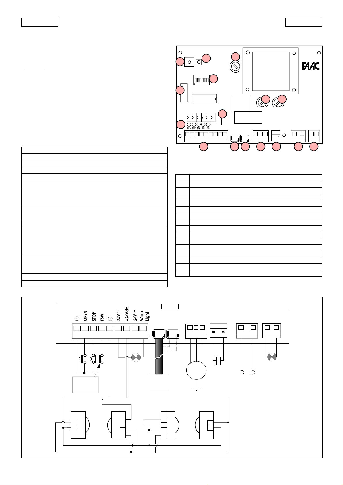
5.1.1. 844MPS ELECTRONIC CONTROL UNIT
Led
J2
TABLE 2 TECHNICAL CHARACTERISTICS OF 844MPS
Power supply 230V~ (+6 -10 %) 50Hz
Motor max. load 650 W
Accessories power supply 24Vdc/24V~
Accessories max. load 500 mA
Warning light power supply 24V~ (5W max)
Temperature range - 20°C + 55°C
transformer primary
Fuses motor
accessories
Quick connectors - for decoding cards or RP receivers-
- capacitor - limit switch -
Inputs OPEN/STOP/CLOSING SAFETY/LIMIT-SWITCH
warning light
Outputs flashing light
motor
24Vdc/24V~power supply for accessories
pause time (5-10-15-30-60-120-180 sec.)
Logic programming (automatic A1/S1/S2 - semiautomatic E1)
pre-flashing
Motor braking Adjustable by trimmer
TABLE 3 844MPS Control unit components
F1 Fast-acting fuse F1 5x20 F5A/250V (motor )
F2 Time delay fuse F2 5x20 T1,6A/250V (accessories)
F3 Time delay fuse F3 5x20 T250mA/250V (transformer)
P1 RESET button
TR1 Braking adjustment trimmer
DS1 Programming dipswitches
Led Input status indicator LEDs
LK1 Jumper for warning lamp contact
J1 Quick connector for decoding cards/RP receiver
J2 Low voltage inputs/accessories terminal block
J3 Quick connector for limit switch (LH closure)
J4 Quick connector for limit switch (RH closure)
J5 Motor output terminal block
J6 Quick connector for capacitor
J7 Flasher unit output terminal block (230V
J8 Line input terminal block
Safety timing 255 sec.
5. 1. 3. ELECTRICAL CONNECTIONS
F2
F2
TR1
P1
RESET
P1
DS1
DS1
IC1
LK1
1 2 3 4 5 6 7 8 9
J2 J5 J6 J8 J7
LK1
J3
RL2
F3
RL1
J5
J4J3
CH- DXCH- SX
J4
F1F3
F1
J6
844MPS
J8
Fig. 23
~ max 60W)
J7
J2
1 2 3 4 5 6 7 8 9
Altre sic urezze
Other s afeties
Autres sécurités
Andere Sicherh eiten
Otros disp. seg.
a
2
1
1
2
3
4
5
Warn.Li ght
5W max
844MPS
FINECORSA
LIMIT SWITCH
FIN DE COURSE
ENDSCHALTER
FIN DE CARRERA
1
2
3
4
5
CH-DXCH-SX
18
J4J3
J5 J6
M
C
35µF
J8
LN
230V~ 50Hz
(+6% -10%)
J7
(L)
FAACLAMP
MINILAMP
b
2
1
Fig. 24
Page 2
ENGLISH
ENGLISH
5.2. DESCRIPTION
5.2.1. CONNECTOR J1
The connector J1 is used for the quick connection of
MINIDEC,DECODER, RP RECEIVER boards (Figs. 25,26,27).
Accessory boards are to be inserted with their component
sides facing the inside of the 844MPS electronic control unit.
Always disconnect the power supply before inserting or
removing accessory boards.
Fig. 27
844MPS
844MPS
PLUS
MINIDEC
SL/DS
Fig. 26Fig. 25
844MPS
DECODER
SL/SLP/DS
5.2.2. TERMINAL BLOCK J2 (low voltage)
1& 5
=Common/Negative of accessory power supply (-)
2 = OPEN control device (N.O.)
Any control device (pushbutton, detector,..) which,
on closing the contact, relays an open and/or close
impulse to the gate.
To install more than one Open control device,
connect the N.O. contacts in parallel.
3 = STOP control device (N.C.)
Any control device (e.g. pushbutton) which, on
opening a contact, stops the movement of the gate.
T o install more than one Stop control de vice, connect
the N.C. contacts in series.
ÜIf no Stop control devices are to be connected,
place a jumper across the input and the common
terminal (terminal 1 or 5).
4 = FSW closure safety device (N.C.)
Any control device (photocells, safety edges,
magnetic loops) with an N.C. contact which
interrupts the movement of the gate when an
obstacle is detected within the protected area.
The task of the closure safety device is to safeguard
the area occupied by the gate during the closing
movement.
The intervention of safety devices during gate
closure causes the direction of gate movement to
be reversed. These devices do not intervene during
gate opening movements. If a closure safety device
is tripped when the gate is open or during a pause
time, they will prevent gate closure.
To install more than one safety device, connect the
N.C. contacts in series.
ÜIf no closure safety devices are to be installed,
place a jumper across this input and the commmon
terminal (terminal 1or5).
&
8 = 24V~ accessories power supply
6
The maximum load of the accessories is 500mA.
To calculate power draw, refer to the instructions for
the individual accessories.
ÜIf the jumper LK1 is broken, the 24V~ accessories
power supply is no longer available (Fig.28).
7 = 24Vdc
accessories power supply positive (+)
The maximum load of the accessories is 500mA.
To calculate power draw, refer to the instructions for
the individual accessories.
9 = Warning Light output
For information regarding operation of the warning
light, refer to the section on dipswitch programming.
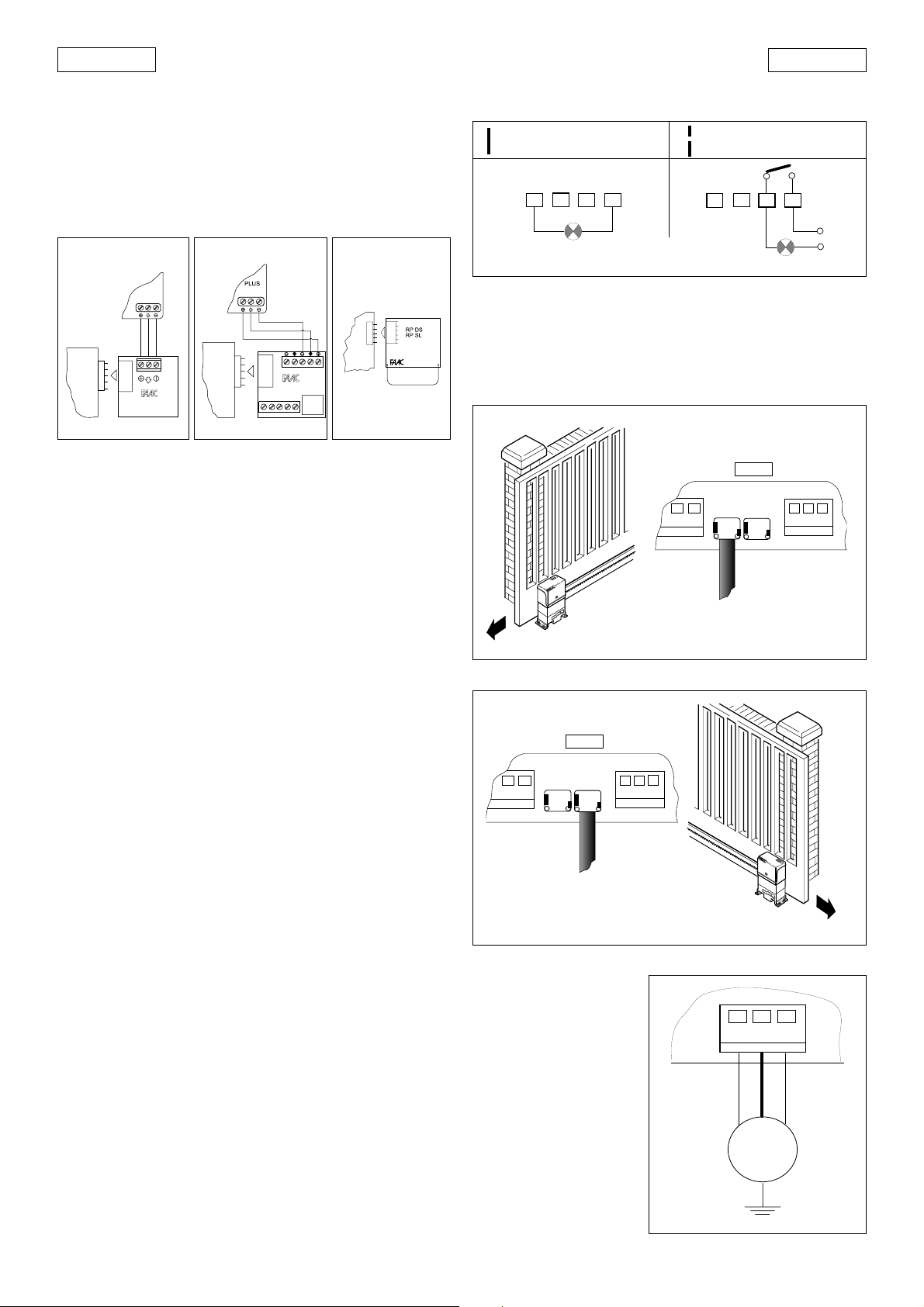
Jumper LK1 allows you to free the warning light contact (Fig.28).
LK1 BROKEN
LK1 INTACT
7
6
8
24V~ 5W max
9
Fig. 28
)
(free contact)
7
6
8
2A max
9
5.2.3. CONNECTORS J3-J4 (limit switch)
J3 = Connection of limit switch for left-hand closure
J4 = Connection of limit switch for right-hand closure
Refer to Figs. 29-30 for quick connection of the inductive limit
switch sensor for the corresponding gate closure direction.
844MPS
J4J3
CH-DXCH-SX
J5
Fig. 29
844MPS
J4J3
CH-DXCH-SX
J5
Fig. 30
5.2.4. TERMINAL
BLOCK J5 (high
voltage)
Terminal block for motor
J5
connection.
ÜConnect the wires to
the terminals of J5 as
shown in Fig.31.
B
LACK AND BROWN WIRES
=
BLUE
BROWNBLACK
electric motor supply
phases
B
LUE WIRE
= electric motor
M
common
Fig. 31
19
Page 3

ENGLISH
ENGLISH
5.2.5. CONNECTOR J6 (high voltage)
Connector for quick connection of the capacitor.
5.2.6. TERMINAL BLOCK J7 (high voltage)
230V~ terminal block for connection of the flashing light (max
60W).
5.2.7. TERMINAL BLOCK J8 (high voltage)
Terminal block for connection of the 230V~ 50Hz power supply
(L=Line N=Neutral)
Connect the earth wire to the operator as shown in Fig.32.
Fig. 32
5.2.8. INDICATOR LEDS
5 LEDs on the board indicate the status of the terminal imputs:
LED
ON
= contact closed
LED
OFF
= contact open
To program the operation of the automation, set the dipswitches
as shown in the diagram above.
Ü Press the RESET button after all programming operations.
Operating logics
There are four operating logics available:
A1 = Automatic S1 = Safety
S2 = Safety Plus E = Semi-automatic
Operation of the different logics is described in tables 5-6-7-8.
Pause time
The pause time is amount of time the gate remains open before
it re-closes when an automatic control logic is selected.
Pause times include the pre-flashing time, if selected.
Warning light operation
Allows you to vary the flashing rate of the warning light during
gate closure.
Pre-flashing
It is possible to select 5 seconds pre-flashing of the flashing light
before any gate movement. This serves to warn any persons in
the vicinity that the gate is about to start moving.
TABLE 5 LOGIC A1 (AUTOMATIC)
LOGIC A1
GATE STATUS
CLOSED
OPEN
CLOSING
OPENING
STOPPED
OPEN
opens and recloses after
pause time (1)
recloses after 5 s (2)
inverts motion
no effect
recloses (1)
IMPULSES
STOP
no effect
stops counting
stops
stops
no effect
SAFETY
no effect
freezes pause until
disengagement
inverts motion
no effect
no effect
LK1
J2
1 2 3 4 5 6 7 8 9
TABLE 4 MEANING OF STATUS INDICATOR LEDS
LED ON OFF
OPEN
STOP
FSW
FCC
FCA
Command active Command not active
Command not active Command active
Safeties disengaged Safeties engaged
Closing limit disengaged Closing limit engaged
Opening limit disengaged Opening limit engaged
5.3. DIPSWITCH SETTINGS
Logic SW1 SW2
E1 ON ON
A1 ON OFF
S2 OFF O N
S1 OFF OFF
ON
123456
OFF
Fig. 33
Pause time (sec)
Logic
A1 - S2 S1 SW3 SW4
515ONON
10 30 OFF ON
30 60 ON OFF
120 180 OFF OFF
TABLE 6 LOGIC S1 (SAFETY)
LOGIC S1
GATE STATUS
CLOSED
OPEN
CLOSING
OPENING
STOPPED
OPEN
opens and recloses after
pause time (1)
recloses immediately
(1 and 2)
inverts motion
inverts motion
recloses (1)
TABLE 7 LOGIC S2 (SAFETY PLUS)
LOGIC S2
GATE STATUS
CLOSED
OPEN
CLOSING
OPENING
STOPPED
OPEN
opens and recloses after
pause time (1)
recloses immediately
(1 and 2)
inverts motion
inverts motion
recloses (1)
TABLE 8 LOGIC E1 (SEMI-AUTOMATIC)
LOGIC E1
GATE STATUS
CLOSED
OPEN
CLOSING
OPENING
STOPPED
OPEN
opens (1)
recloses (1)
inverts motion
stops
recloses (reopens when safety
devices are engaged) (1)
IMPULSES
STOP
no effect
stops counting
stops
stops
no effect
IMPULSES
STOP
no effect
stops counting
stops
stops
no effect
IMPULSES
STOP
no effect
no effect
stops
stops
no effect
SAFETY
no effect
recloses after 5 s
from disengagement
inverts motion
no effect
no effect
SAFETY
no effect
freezes pause until
disengagement
stops and inverts motion
when disengaged (1)
no effect
no effect
SAFETY
no effect
no effect
inverts motion
no effect
no effect
Warning light operation
Gate status
SW5
Closed Opening/Open Closing
ON
OFF Steady light
OFF
Steady light
Flashing
Pre-flashing SW6
YES ON
NO OFF
(1) With the pre-flashing selected, movement starts after 5 seconds.
(2) If the impulse is sent during pre-flashing, the timer is reset to zero.
20
 Loading...