

FAAC 844 User Manual
844
Slide Gate Operator
UL325 - UL991
FAAC International Inc.
Headquarter & East Coast Operations
3160 Murrell Rd
Rockledge, FL 32955
Tel. 800 221 8278
www.faacusa.com
FAAC International Inc.
West Coast Operations
357 South Acacia Avenue
Fullerton, CA 92831

TABLE OF CONTENTS
IMPORTANT SAFETY INFORMATION 3
Important Safety Instructions 3
Important Installation Instructions 3
General Safety Precautions 4
UL325 Gate Operator Classifications 5
Installing the Warning Signs 5
1. DESCRIPTION & SPECIFICATIONS 6
1.1. Maximum Use Curve 6
1.2 Technical Specifications 6
2. DIMENSIONS 7
3. ELECTRIC LAYOUT 7
4. INSTALLATION 7
4.1. Preliminary Checks 7
4.2. Foundation Plate Installation 7
4.3. Mechanical Installation 8
4.4. Installing The Rack 8
4.5. Installation Of Chain Pinions 9
5. CONTROL BOARD 780D 10
5.1. Warnings 10
5.2. 780D Technical Specifications 10
5.3. Layout And Components 10
5.4. Electric Connections 11
5.5. Programming 13
6. START-UP 16
6.1. Electric Connections 16
6.2. Opening - Closing Directions 16
6.3. Determining Stop Points At Travel Limit 16
6.4. Inputs Check 17
6.5. Mechanical Clutch Adjustment 17
6.6. Travel Limits Check 17
6.7. Safety Devices Check 17
7. FINAL OPERATIONS 18
8. MANUAL OPERATION 18
9. RESTORING NORMAL OPERATION 18
10. MAINTENANCE 19
10.1. Removing Board And Transformer 19
10.2. Oil Top-Offs 19
10.3. Repairs 19
11. LOGICS TABLES 20
12. SPARES PARTS DIAGRAM 22
13. TROUBLESHOOTING 24
844ER_732242_RevB_US - Jan 2017
2

IMPORTANT SAFETY INFORMATION
Important Safety Instructions
WARNING: TO REDUCE THE RISK OF SEVERE INJURY OR
DEATH:
• READ AND FOLLOW ALL INSTRUCTIONS.
• Never let children operate or play with the gate
controls. Keep remote controls away from children.
• Always keep people and objects away from the
gate. NO ONE SHOULD CROSS THE PATH OF A
MOVING GATE.
• Test the gate operator monthly. The gate MUST
reverse on contact with a rigid object or when an
object activates a non-contact sensor. If necessary,
adjust the force or the limit of travel and then retest
the gate operator. Failure to properly adjust and
retest the gate operator can increase the risk of injury
or death.
• Use the manual release mechanism only when the
gate is not moving.
• KEEP GATE PROPERLY MAINTAINED. Have a qualified
service person make repairs to gate hardware.
• The entrance is for vehicles only. Pedestrians must use
a separate entrance.
• SAVE THESE INSTRUCTIONS.
Important Installation Instructions
1. Install the gate operator only when the following conditions have been met:
• The operator is appropriate for the type and usage
class of the gate.
• All openings of a horizontal slide gate have been
guarded or screened from the bottom of the gate
to a minimum of 6 feet (1.83 m) above the ground
to prevent a 2-1/4 inch (57.2 mm) diameter sphere
from passing through openings anywhere in the gate
or through that portion of the adjacent fence that the
gate covers when in the open position.
• All exposed pinch points are eliminated or guarded.
• Guarding is supplied for exposed rollers.
2. The operator is intended for installation on gates used by
vehicles only. Pedestrians must be provided with a separate access opening.
3. To reduce the risk of entrapment when opening and
closing, the gate must be installed in a location that
allows adequate clearance between the gate and
adjacent structures. Swinging gates shall not open
outward into public access areas.
4. Before installing the gate operator, ensure that the gate
has been properly installed and that it swings freely in
both directions. Do not over-tighten the operator clutch
or pressure relief valve to compensate for a damaged
gate.
5. Controls intended for user activation must be located
at least six feet (6’) away from any moving part of the
gate and where the user is prevented from reaching
over, under, around or through the gate to operate the
controls.Exception: Emergency access controls only
accessible by authorized personnel (e.g. fire, police, EMS)
may be placed at any location in the line-of-sight of the
gate.
6. The Stop and/or Reset buttons must be located within
line-of-sight of the gate. Activation of the reset control
shall not cause the operator to start.
7. All warning signs and placards must be installed and
easily seen within visible proximity of the gate. A minimum
of one warning sign shall be installed on each side of the
gate.
8. For gate operators that utilize a non-contact sensor
(photo beam or the like):
• See instructions on the placement of non-contact
sensors for each type of application.
• Exercise care to reduce the risk of nuisance tripping,
such as when a vehicle trips the sensor while the gate
is still moving.
• Locate one or more non-contact sensors where the
risk of entrapment or obstruction exists, such as at the
reachable perimeter of a moving gate or barrier.
• Use only FAAC “Photobeam” photoelectric eyes to
comply with UL325.
9. For gate operators that utilize a contact sensor (edge
3

Important Installation Instructions (continued)
sensor or similar):
• Locate one or more contact sensors where the risk
of entrapment or obstruction exists, such as at the
leading edge, trailing edge, and post mounted
both inside and outside of a vehicular horizontal
slide gate
• Locate one or more contact sensors at the bottom
edge of a vehicular vertical lift gate.
• Locate one or more contact sensors at the bottom
edge of a vertical barrier (arm).
• Locate one or more contact sensors at the pinch
point of a vehicular vertical pivot gate.
• Locate hard-wired contact sensors and wiring so
that communication between sensor and gate
operator is not subjected to mechanical damage.
• Locate wireless contact sensors, such as those
that transmit radio frequency (RF) signals, where
the transmission of signals are not obstructed or
impeded by building structures, natural landscaping or similar hindrances. Wireless contact
sensors shall function under their intended end-use
conditions.
• Use only FAAC XS 55, CN 60 E edge sensors.
General Safety Precautions
Gate Construction
Vehicular gates should be constructed and installed in
accordance with ASTM F2200: Standard Specification for
Automated Vehicular Gate Construction.
For more information, contact ASTM at: www.astm.org
Installation
• If you have any questions or concerns regarding the
safety of the gate operating system, do not install the
operator and consult the manufacturer.
• The condition of the gate structure itself directly affects
the reliability and safety of the gate operator.
• Only qualified personnel should install this equipment.
Failure to meet this requirement could cause severe
injury and/or death, for which the manufacturer cannot
be held responsible.
• The installer must provide a main power switch that
meets all applicable safety regulations.
• It is extremely unsafe to compensate for a damaged
gate by increasing hydraulic pressure.
• Install devices such as reversing edges and photo
beams to provide better protection for personal
property and pedestrians. Install reversing devices that
are appropriate to the gate design and application.
• Before applying electrical power, ensure that voltage
requirements of the equipment correspond to the
supply voltage. Refer to the label on your gate operator
system.
Usage
• Use this equipment only in the capacity for which it was
designed. Any use other than that stated should be
considered improper and therefore dangerous.
• The manufacturer cannot be held responsible
for damage caused by improper, erroneous or
unreasonable use.
• If a gate system component malfunctions, disconnect
the main power before attempting to repair it.
• Do not impede the movement of the gate, you may
injure yourself or damage the gate system as a result.
• This equipment may reach high thermal temperatures
during normal operation, therefore use caution when
touching the external housing of the gate operator.
• Use the manual release mechanism according to the
procedures presented in this manual.
• Before performing any cleaning or maintenance
operations, disconnect power to the equipment.
• All cleaning, maintenance or repair work must be
performed by qualified personnel.
4

UL325 Gate Operator Classifications
RESIDENTIAL VEHICULAR GATE OPERATOR CLASS I
A vehicular gate operator system intended for use in a single family dwelling, garage or associated parking area.
COMMERCIAL / GENERAL ACCESS VEHICULAR GATE OPERATOR CLASS II
A vehicular gate operator system intended for use in commercial locations or buildings such as multi-family housing
units (five or more single family units), hotels, parking garages, retail stores or other buildings that service the general
public.
INDUSTRIAL / LIMITED ACCESS VEHICULAR GATE OPERATOR CLASS III
A vehicular gate operator system intended for use in industrial locations or buildings such as factories, loading docks
or other locations not intended to service the general public.
RESTRICTED ACCESS VEHICULAR GATE OPERATOR CLASS IV
A vehicular gate operator system intended for use in guarded industrial locations or buildings such as airport security
areas or other restricted access locations that do not service the general public, and in which unauthorized access
is prevented via supervision by security personnel.
Installing the Warning Signs
This FAAC slide gate operator is supplied with two warning
signs to alert people that a possible hazard exists and that
appropriate actions should be taken to avoid the hazard
or to reduce exposure to it.
Permanently install one warning sign on each side of the
gate so they are fully visible to traffic and pedestrians.
Use appropriate hardware such as metal screws (not supplied) to permanently install each warning sign.
5
844 OPERATOR
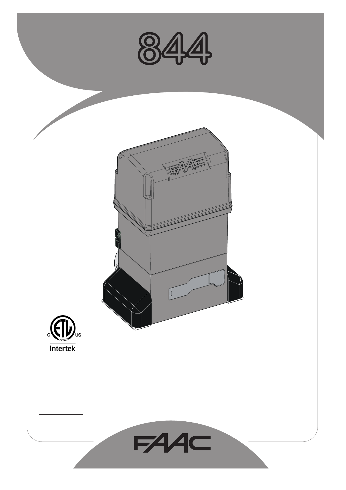
1. DESCRIPTION AND SPECIFICATION
The FAAC Model 844 is an electro-mechanical operator for
sliding gates transmitting motion to the sliding leaf via a rack or
chain pinion appropriately coupled to the gate.
The non-reversing system ensures the gate is mechanically
locked when the motor is not operating and, therefore, no lock
needs to be installed.
The gearmotor is equipped with a mechanical clutch which,
combined with an electronic device, offers the necessary adjustable anti-crushing safety and guarantees stopping or reversing
the gate movement. A handy manual release makes it possible
to move the gate in the event of a power cut or malfunction.
The control board, if supplied with the gearmotor, it is placed
inside the operator.
The 844 automated system is designed and manufactured to
control access of vehicles. Do not use for any other purpose.
Fig. 1
where:
Ta = opening time
Tc = closing time
Tp = pause time
Ti = time of interval between two complete cycles
Use Frequency Graph
% Freq. Used % Duty Cycle
100
90
80
70
60
50
40
30
20
10
1. Mounting Brackets
2. Pinion
3. Limit Sensor Switch
4. Operator Cover
5. 780 D Control Board
6. Adjustment Screw for
Anti-crushing Clutch
7. Oil Filling Plug
8. Operator Grounding
9. Lever Operated Release
System
10. Protective Side Panels
11. Cover for 780D Control
Board
1.1. Maximum Use Curve
The curve makes it possible to establish maximum work time (T)
according to use frequency (F). The 844 gearmotor can operate
non-stop at 70% use frequency.
To ensure efficient operation, operate in the work range below
the curve.
Important: The curve is obtained at a temperature of 75°F. Exposure to direct sunlight can reduce use frequency down to 20%.
Calculating Use Frequency
The percentage of effective work time (opening + closing) compared to total time of cycle (opening + closing + pause times).
Calculation formula:
Ta + Tc
%F = X 100
Ta + Tc + Tp + Ti
12 3456789101112
0
Time (h)
1.2 Technical Specifications
Type of Pinion
Power Supply
Absorbed Power
Reduction Ratio
Max. Thrust
Max. Torque
Winding Thermal Protection
Use Frequency 70% (see graph)
Oil Quantity
Type of Oil
Ambient Operating Temperature
Weight
Protection Class
Gate Max. Weight
Gate Speed
Gate Max. Length
Clutch twin-disk in oil bath
Protective Treatment cataphoresis
Control Board
Limit-Switch magnetic or inductive
Overall Dimensions L x H x D
Electric Motor Technical Specifications
Rotation Speed
Power
Current
Starting Capacitor
Power Supply
Z16 Z20
115 Vac (+
10% -6%)
650 W
1 : 30
247 lbf 198 lbf
26 lbf.ft
248
°F
1.9 qt
FAAC HP
-4 to +131
°F
32 lb
IP 44
3950 lb 2200 lb
38 ft/min
131 ft
47 ft/min
164 ft
780D
See Fig. 2
1700 r.p.m
650 W
7 A
70
µF
115 Vac (+
10% -6%)
6
¾0
6
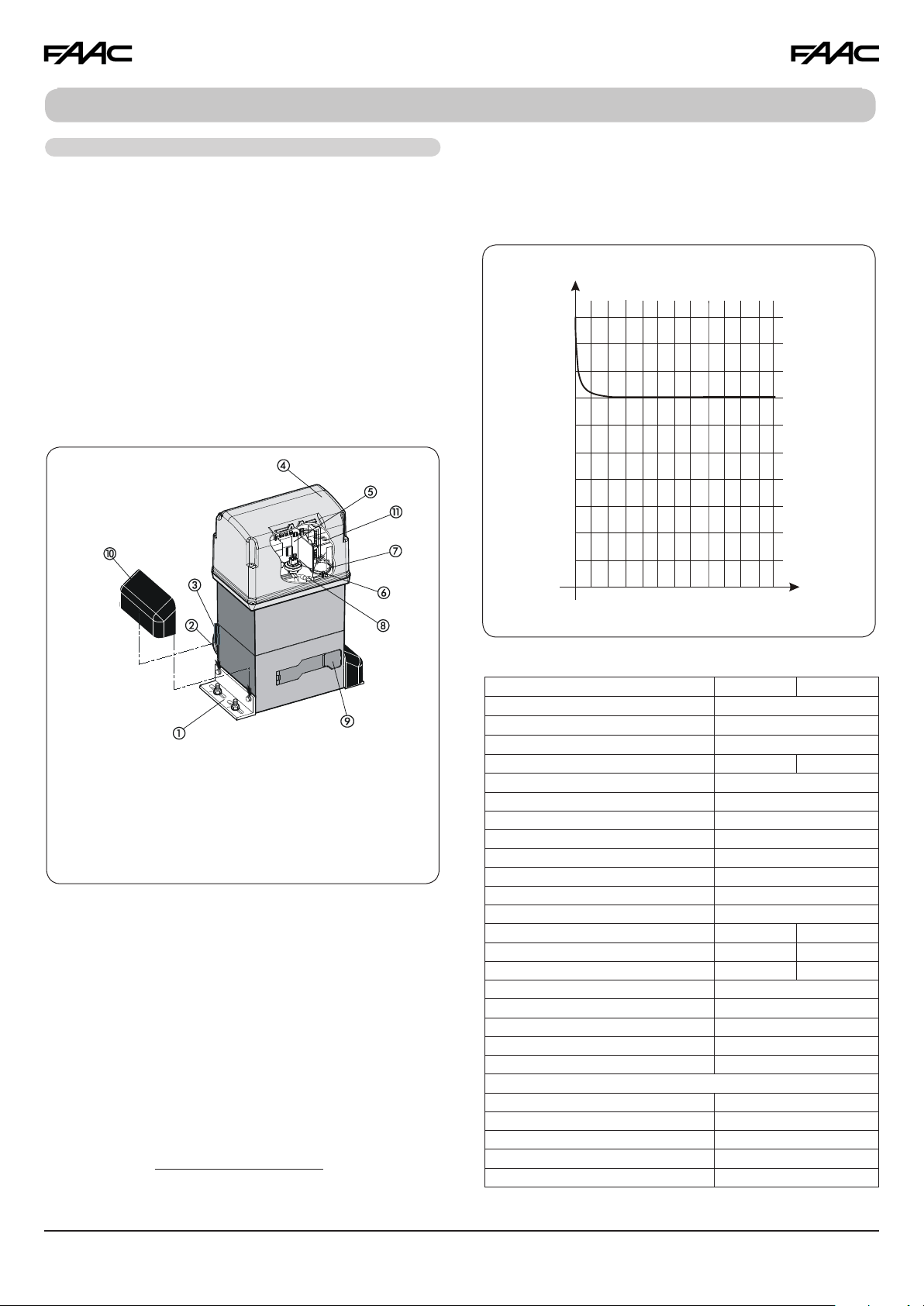
2. DIMENSIONS
8 ¾
10 ¾
Fig. 2
- Measurements in Inches
3. ELECTRICAL LAYOUT
VAC ~ 15 AWG
20 AWG
Operator 844
Photocells
Key-operated push-button
Flashing lamp
Radio receiver
15 ¼
7 ½
20 AWG
20 AWG
15 AWG
20 AWG
Fig. 3
2.5 in
2
- Measurements in Inches
Fig. 6
Fig. 4
Fig. 5
8
to 2
2
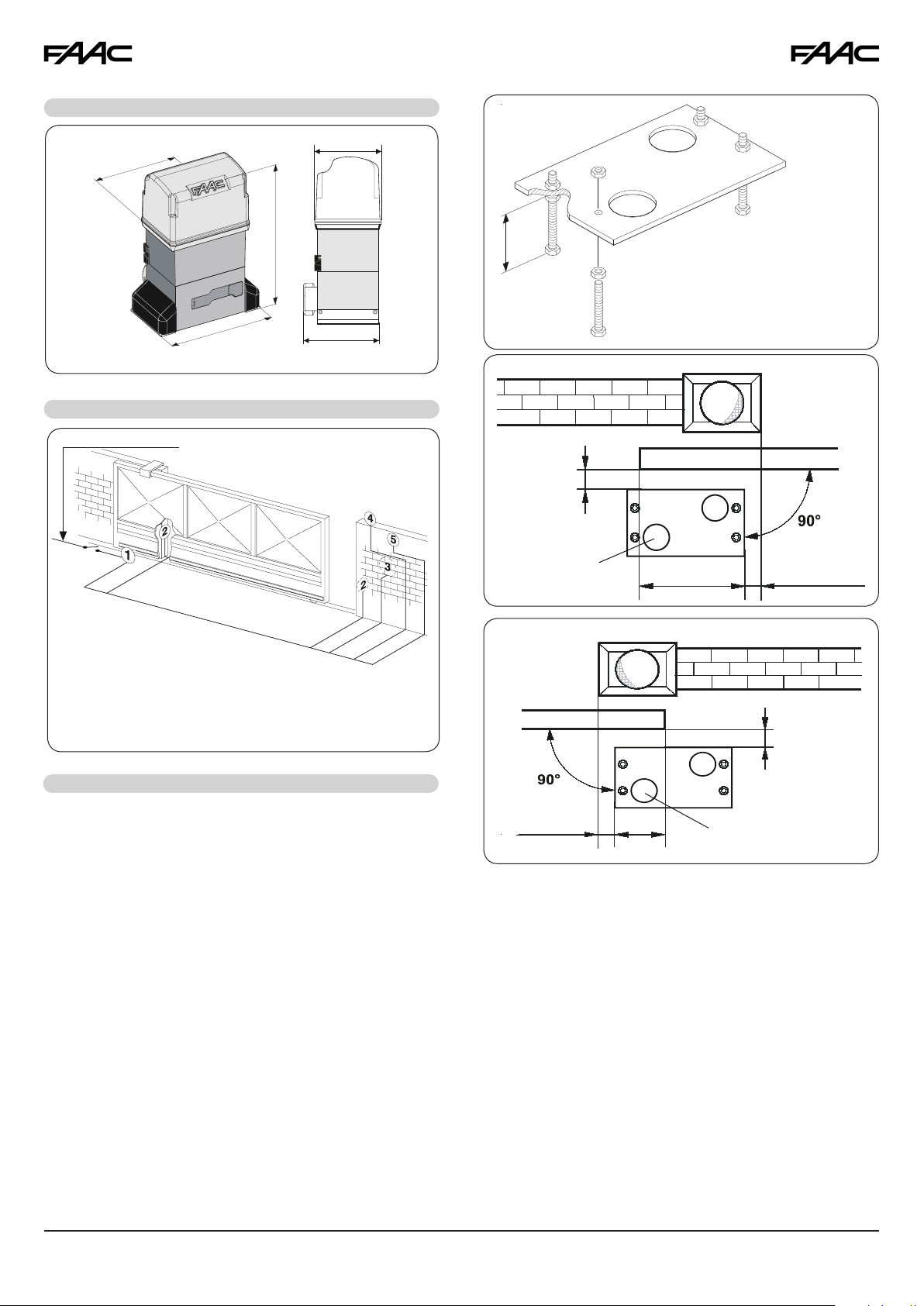
4. INSTALLATION
4.1. Preliminary Checks
To ensure safety and an efficiently operating automated system, make sure the following conditions are observed:
• The gate structure must be suitable for automation. For
example, wheel diameter must be in proportion to the
weight of the gate to be automated, an upper guide
must be provided, mechanical stop limits to prevent the
gate derailing must be installed.
• The soil must permit sufficient stability for the concrete pad.
• There must be no pipes or electric cables in the pad
excavation area.
• If the operator is exposed to passing vehicles, install, if
possible, adequate means of protection against accidental impact.
• Check if an efficient grounding is available for connection
to the gearmotor.
4.2. Foundation Plate Installation
1. Assemble the foundation plate as shown in Fig 4. The
foundation plate must be located as shown in Fig 5 (right
closing) or Fig 6 (left closing) to ensure that the rack and
pinion mesh correctly.
0 to 2
6
- Measurements in Inches
2. Prepare a concrete pad as shown in Fig.7, following the
suggested dimensions. It’s recommended to have the pad
a minimum of 4” above level grade to avoid any flooding
of the operator. The underground depth of the concrete
pad is determined by the soil condition and the local
building codes. Make sure the concrete pad is leveled.
3. Provide one or more conduit pathways for all power and
accessory connections. Extend the conduit about of 1/2”
above the level of the concrete pad.
4. After the concrete is poured in the forms and before it
has a chance to set, insert the foundation plate into the
cement and position it flush with the top of the concrete
and aligned with the top of the lower gate frame. Use the
dimensions shown in Figs 5 or 6 to align your foundation
plate. Allow the concrete to set for a minimum of two days
before installing the operator.
5. Route the wires in the conduits. To facilitate the connections allow for about 15” of extra length of cables out of
the conduit. Separate the high and low voltage wires in
different conduits.
7
- Measurements in Inches
4 ⅜ (Z16)
- Measurements in Inches
Fig. 7
11.5
Fig. 11
3
1.75
6.25
3
2⅜
4
7
2⅜
1.75
- Measurements in Inches
0.25
12.25
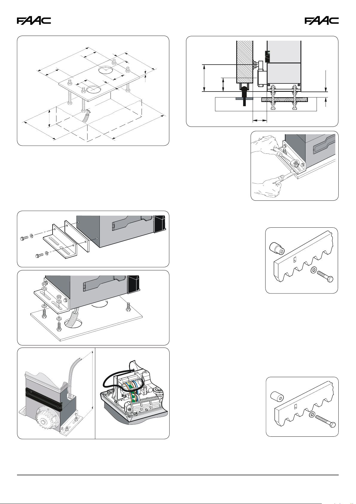
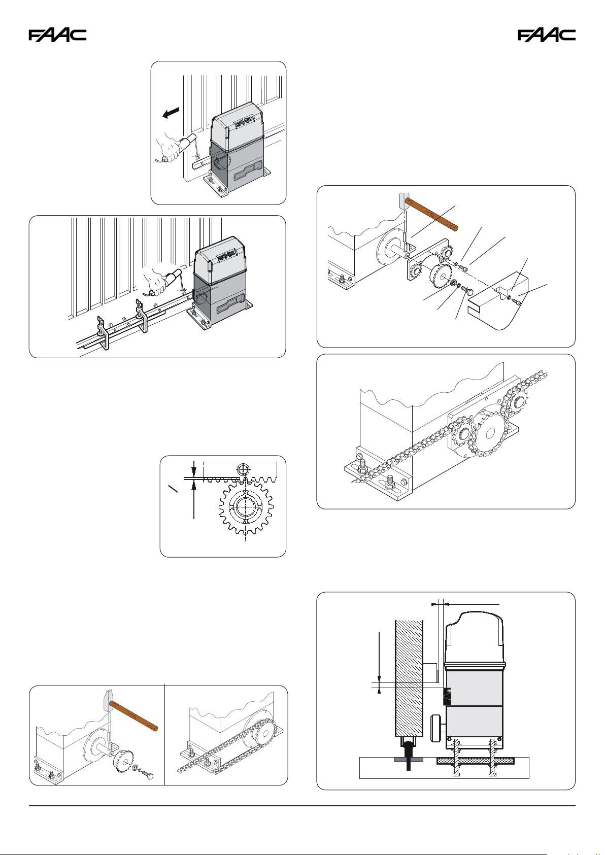
4.3. MECHANICAL INSTALLATION
1. Assemble the mounting brackets and anti-vibration spacers
on the operator as shown in Fig. 8.
2. Open the cover, remove the securing screws.
3. Attach the operator to the plate, using the supplied washers
and nuts as shown in Fig. 9. During this operation, route
cables through the opening inside the lower half-casing
of the operator (Fig.10 - Ref. A).
Fig. 8
Fig. 9
Fig. 10BFig. 10A
4 ¾ (Z20)
2 ½
⅝ to 1 ¼
2
4. Adjust the height
and distance from
the gate as shown
in Fig 11.
5. Secure the operator to the foundation plate, tighten
nuts as shown in
Fig. 12.
Fig. 12
4.4. INSTALLING THE RACK
4.4.1. STEEL RACK TO WELD (Fig. 13)
1. Place the three threaded
dowel nuts on the rack
element, positioning them
at the top of the slot. In
this way, the slot play will
allow any adjustments to
be made.
2. Manually move the leaf to
its closed position.
3. Lay the first piece of rack
level on the pinion and weld the threaded dowel nut to the
gate as shown in Fig. 15.
4. Move the gate manually, checking that the rack is resting
on the pinion, then weld the second and third dowel nut.
5. Place another rack element next to the previous one, use
a third piece of rack (as shown in Fig. 16) to synchronize
the teeth of the first two elements.
6. Move the gate manually and weld the three threaded
dowel nuts. Proceed as described until the gate is fully
covered.
4.4.2. STEEL RACK TO SCREW (Fig. 14)
Fig. 13
To access the electronic board, route the cables through the
appropriate hole, using the supplied rubber cable-clamp.
Make sure to strip the jacket on all cables so that the clamp
holds single cables only (Fig.10 - Ref. B).
15 ¾
1. Manually move the leaf to
its closing position.
2. Lay the first piece of rack
level on the pinion and
place the spacer between
the rack and the gate,
positioning it at the top of
the slot.
3. Mark the drilling point on the
gate. Drill a Ø ¼ inch hole and apply thread with a Ø 5/16
inch male tap. Screw in the bolt.
4. Move the gate manually, checking that the rack is resting
on the pinion. Repeat step 3.
8
Fig. 14
1
⅛ to ½
- Measurements in Inches
6. Place another rack element next to the previous one, use a third
piece of rack (as shown
in Fig. 16) to synchronize
the teeth of the first two
elements.
7. Move the gate manually and secure the
first element. Proceed
as previously described
until the gate is fully
covered.
Fig. 15
4.5.2. MODEL 844 ER RF (Figs. 20 & 21)
3. Insert the pin g on the shaft, using a hammer.
4. Fit the idle transmissions bracket on the operator flange,
using the four screws a (M5 x 12) and the appropriate washers b, in the kit as shown in Fig. 20.
5. Fit the chain pinion on the shaft, making the channel coincide with the pin and tighten the screw d and the appropriate
washers e and f.
6. Pass the chain as shown in Fig. 21A and install the cover
with screw a and washer c as in Fig. 20.
Fig. 20
g
b
a
c
a
f
e
d
Fig. 16
Notes on Rack Installation
• Make sure that, during gate travel, no rack elements derail
from the pinion.
• Do not, for any reason, weld the rack elements either to the
spacers or to each other.
• When the rack has been installed, to ensure that it meshes
correctly with the pinion, lower the gearmotor position by
about 1/16 inch (Fig. 17).
• Manually check that the
gate regularly reaches
the mechanical stop li-
inch
16
mits and make sure there
is no friction during gate
travel.
• Do not use grease or other
lubricants between rack
Fig. 17
and pinion.
4.5. INSTALLATION OF CHAIN PINIONS
The operators for chain and idle transmissions require the installation of a Z16 or Z20 chain pinion.
4.5.1. MODEL 844 ER CAT (Figs. 18 & 19)
1. Insert the pin on the shaft, using a hammer.
2. Fit the chain pinion on the shaft, making the channel coincide with the pin. Tighten the screw and the appropriate
washers.
Fig. 18
Fig. 19
Fig. 21A
4.5.3. LIMIT SWITCHES
In case of operators with magnetic limit switches, you have to
provide a bracket to mount them on the gate, following the
proper distances shown in Fig. 21B.
Fig. 21B
0 to ⅜
9
 Loading...