

Page 1

5. START-UP
5.1. CONNECTION TO ELECTRONIC CONTROL UNIT
Warning: Always turn off the electricity supply before
carrying out any work on the electronic control unit
(connections, programming, maintenance).
Warning: When terminal board J2 is disconnected, high
voltage remains on the outputs of the capacitor, motor and
transformer power supplies.
Observe points 10, 11, 12, 13 and 14 in the GENERAL SAFETY
INSTRUCTIONS.
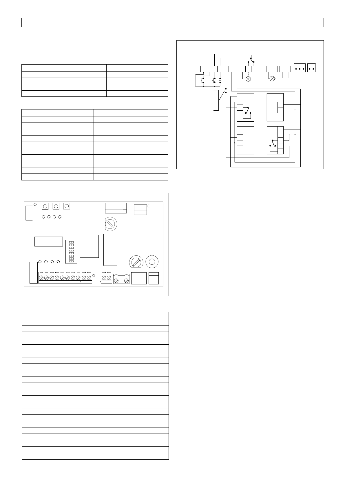
As shown in Fig. 2, prepare the conduits and make the
electrical connections from the 826 MPS electronic control
unit to the chosen accessories.
Page 2
ENGLISH
123456
78910
11
12
-
+
-
1
2
3
4
5
1
2
3
4
5
1
2
1
2
FX1
FX2
OPEN
A/C
STOP
FX
230 V
+6% -10%
50-60 Hz
FAAC
LAMP
LAMP
24V 3W
13
14
ENGLISH
Always route the power supply cables separately from the
control and safety cables (keyswitch, receiver, photocells,
etc.). Use separate conduits to avoid any interference.
TABLE 2 TECHNICAL CHARACTERISTICS OF 826 MPS
POWER SUPPLY 230 V (+6 -10%) 50 Hz
MAX. MOTOR LOAD 600 W
MAX. ACCESSORIES LOAD 500 mA
MAX. WARNING LAMP POWER 5 W (24Vac)
TEMPERATURE RANGE - 20°C + 55°C
TABLE3 ACCESSORIES CURRENT DRAW
TYPE OF ACCESSORY NOMINAL CURRENT DRAW
R 31 50mA
PLUS 433 E 20mA
MINIDEC SL / DS 6mA
DECODER SL / DS 20mA / 55mA
RP 433 ESL / EDS 12mA / 6mA
DIGICARD 15mA
METALDIGIKEY 15mA
FOTOSWITCH 90mA
DETECTOR F4 / PS6 50mA
MINIBEAM 70mA
5.1.1. 826 MPS CONTROL UNIT
J3
P3
P2
P1
LD5 LD6 LD7 LD8
1
2
43
65
J1
DECODER
LD2 LD3 LD4
LD1
1
87
DS1
4
32
765
Table 4 826 MPS control unit components
LD1 OPEN LED
LD2 PARTIAL OPEN/CLOSE LED
LD3 STOP LED
LD4 SAFETY LED
LD5 LIMIT SWITCH ALARM LED
LD6 OPENING LIMIT SWITCH LED
LD7 CLOSURE LIMIT SWITCH LED
LD8 SLIDING SPEED LED
P1 OPENING LIMIT SWITCH PROGRAMMING BUTTON
P2 CLOSURE LIMIT SWITCH PROGRAMMING BUTTON
P3 LIMIT SWITCH / RESET PROGRAMMING BUTTON
J1 DECODER CONNECTOR
J2 LOW VOLTAGE TERMINAL BLOCK
J3 ADL CONNECTOR
J4 FAAC LAMP OUTPUT TERMINAL BLOCK
J5 CAPACITOR CONNECTOR
J6 ELECTRIC MOTOR CONNECTOR
J7 TRANSFORMER PRIMARY CONNECTOR
J8 TRANSFORMER SECONDARY CONNECTOR
J9 230 Vac POWER SUPPLY TERMINAL STRIP
F1 ELECTRIC MOTOR FUSE (F 5 A)
F2 ACCESSORIES FUSE (T 1.6 A)
DS1 PROGRAMMING DIPSWITCH
FAAC
826MPS
J2
F2
J4
J7
J8
F1
J6
J9
MOTOR
141312111098
J5
CAP.
Fig. 22
5.1.2. ELECTRICAL CONNECTIONS
CONTATTO COSTA DI SICUREZZA
SAFETY EDGE CONTACT
CONTACT TRANCHE DE SÉCURITÉ
KONTAKT SICHERHEITSKANTE
CONTACTO BANDA DE SEGURIDAD
Fig. 23a
5.2. DESCRIPTION OF TERMINAL BLOCK
5.2.1. OPEN (terminals 1-2)
This means any control device with a N.O. contact which
causes the gate to open when activated. In automatic
and semiautomatic logics it is active for both opening and
closure.
5.2.2. A/C (terminals 1-3)
This means any control device with a N.O. contact which
causes partial opening of the gate when activated in E1,
E2, A1, A2, S1 and S2 logics. In B and C logics it causes the
gate to close.
5.2.3. STOP (terminals 1-4)
This means a control device with a N.C. contact which
causes the gate status (opening-pause-closure) to be
interrupted until the next impulse is sent.
N.B.: If stop devices are not connected, jumper terminals 1-4.
5.2.4. SAFETY FX (terminals 5 - 6)
This means all devices (photocells, safety edges, magnetic
loops) with a N.C. contact which stop the movement of
the gate when an obstacle is present in the area protected
by the safety devices.
N.B.: If stop devices are not connected, jumper terminals 5-6.
5.2.5. + - LOW VOLTAGE POWER SUPPLY (terminals 6 - 7)
These are the 24 Vdc terminals to which the accessories
must be connected.
Proceed as shown in Table 3 in order not to exceed the
maximum permitted load.
5.2.6. LAMP (terminals 8 - 9 - 10)
These are the 24 Vac terminals to which the warning lamp
must be connected.
Warning lamp operation illustrated in Fig. 24 refers to
connection to terminals 8-9. Connecting the warning
lamp to terminals 8-10 gives inverse operation.
5.2.7. FAAC LAMP (terminals 11 - 12)
These are the 230 Vac terminals to which the flashing light
must be connected.
5.2.8. 230 V MAINS SUPPLY (terminals 13 - 14)
These are the terminals to which the 230 Vac electricity
supply must be connected.
Connect the earth cable to the post as shown in Fig. 23b.
5.2.9. BEHAVIOUR OF SAFETY DEVICES
The safety devices operate during closure only. In A1, E1
and S1 logics, interrupting the safety device contacts causes
the gate to stop closing and start opening immediately. In
18
Page 3

ENGLISH
Fig. 23b
A2, E2 and S2 logics interrupting the safety device contacts
causes the gate to stop closing, then to start opening again
when the safety devices are released.
5.2.10. ELECTRONIC SAFETY DEVICE
(models 820 EMC - 860 EMC only)
The operator is equipped with a system which cuts in when
it senses a 20% reduction in pinion speed. The device inverts
the closing movement and inhibits opening movement.
When this safety device cuts in, LED S goes out for a few
seconds. Automatic re-closure is inhibited if the electronic
anti-crushing safety has cut in.
5.3. DIPSWITCH SETTINGS
N.B.: PRESS THE RESET BUTTON AFTER ALL PROGRAMMING
OPERATIONS
Logic SW1 SW2 SW3
E1 ON ON ON
A1 OFF ON ON
S2 ON OFF ON
S1 OFF OFF ON
B ON ON OFF
C OFF ON OFF
E2 ON OFF OFF
A2 OFF OFF OFF
12345678
Gate closure direction as viewed from inside SW8
To right ON
To left OFF
Pre-flashing (2) SW7
Yes ON
No OFF
Warning light operation (3)
Closed Opening/Open Closing
SW6
ON
OFF
(1) Pause times include pre-flashing.
(2) Pre-flashing commences 5 seconds before the start of each
movement.
(3) Warning light connected between 8 and 9 (if connected
between 8 and 10, operation is inverted).
Off
Gate status
Steady light
Pause time (sec) (1)
Logic
A1 A2 S2 S1 SW4 SW5
515ONON
10 30 OFF ON
30 60 ON OFF
120 180 OFF OFF
Steady light
Flashing
Fig. 24
5.4. OPERATION IN VARIOUS LOGICS
TABLE 5 LOGIC E1 (SEMIAUTOMATIC)
LOGIC E1
GATE STATUS
CLOSED
OPEN
CLOSING
OPENING
STOPPED
OPEN - A/C (1) -
opens (2)
recloses (2
inverts motion
stops
recloses (reopens when safety
devices are engaged) (2)
TABLE 6 LOGIC E2 (SEMIAUTOMATIC)
LOGIC E2
GATE STATUS
CLOSED
OPEN
CLOSING
OPENING
STOPPED
OPEN -A/C(1)-
opens (2)
recloses (2)
inverts motion
stops
recloses (reopens when
safety devices are
engaged) (2)
TABLE 7 LOGIC A1 (AUTOMATIC)
LOGIC A1
GATE STATUS
CLOSED
OPEN
CLOSING
OPENING
STOPPED
OPEN - A/C (1) -
opens and recloses after
pause time (2)
recloses after 5 s (3)
inverts motion
no effect
recloses (2)
TABLE 8 LOGIC A2 (AUTOMATIC)
LOGIC A2
GATE STATUS
CLOSED
OPEN
CLOSING
OPENING
STOPPED
OPEN - A/C (1) -
opens and recloses after
pause time (2)
recloses after 5 s (3)
inverts motion
no effect
recloses (2)
TABLE 9 LOGIC S1 (SAFETY)
LOGIC S1
GATE STATUS
CLOSED
OPEN
CLOSING
OPENING
STOPPED
OPEN - A/C (1) -
opens and recloses after
pause time (2)
recloses immediately
(2 and 3)
inverts motion
inverts motion
recloses (2)
TABLE 10 LOGIC S2 (SAFETY)
LOGIC S2
GATE STATUS
CLOSED
OPEN
CLOSING
OPENING
STOPPED
OPEN - A/C (1) -
opens and recloses after
pause time (2)
recloses immediately
(2 and 3)
inverts motion
inverts motion
recloses (2)
TABLE 11 LOGIC B (SEMIAUTOMATIC)
LOGIC B IMPULSES
GATE STATUS
CLOSED
OPEN
CLOSING
OPENING
STOPPED
OPEN
opening (2)
no effect
no effect
no effect
completes
opening (2)
A/C (5)
no effect
closing (2)
no effect
no effect
completes
opening (2)
IMPULSES
STOP
no effect
no effect
stops
stops
no effect
IMPULSES
STOP
no effect
no effect
stops
stops
no effect
IMPULSES
STOP
no effect
stops counting
stops
stops
no effect
IMPULSES
STOP
no effect
stops counting
stops
stops
no effect
IMPULSES
STOP
no effect
stops counting
stops
stops
no effect
IMPULSES
STOP
no effect
stops counting
stops
stops
no effect
SAFETY (until
disengagement)
no effect
inhibits closing
stops
no effect
inhibits closing
ENGLISH
SAFETY
no effect
no effect
inverts motion
no effect
no effect
SAFETY
no effect
no effect
stops and inverts motion
when disengaged (2)
no effect
no effect
SAFETY
no effect
freezes pause until
disengagement
inverts motion
no effect
no effect
SAFETY
no effect
recloses after 5 s
stops and inverts motion
when disengaged (2)
no effect
no effect
SAFETY
no effect
recloses after 5 s
inverts motion
no effect
no effect
SAFETY
no effect
freezes pause until
disengagement
stops and inverts motion
when disengaged (2)
no effect
no effect
STOP
no effect
no effect
stops movement
stops movement
no effect
19
Page 4

ENGLISH
TABLE 12 LOGIC C (DEADMAN)
LOGIC C IMPULSES
GATE STATUS
CLOSED
OPEN
CLOSING
OPENING
STOPPED
OPEN (4)
opens
no effect
no effect
completes opening
A/C (4 and 5)
completes closing
no effect
closes
no effect
SAFETY (until
disengagement)
no effect
inhibits closing
stops
no effect
inhibits closing
(1) The A/C input enables partial opening.
(2) With pre-flashing selected movement starts after 5
seconds.
(3) If the impulse is sent after pre-flashing the timer recounts.
(4) For operation in C logic keep the pushbutton depressed.
Movement stops upon release.
(5) The A/C input controls closure.
5.5. PROGRAMMING LIMIT SWITCHES
IMPORTANT: CHECK THE LENGTH OF THE GATE. THE
OPERATOR HAS A LIMIT SWITCH SYSTEM WHICH ALLOWS
FOR AUTOMATION OF GATES WITH A MAXIMUM LENGTH OF
13 m FOR MODELS 820 (Z 20 PINION) AND 10 m FOR
MODELS 860 (Z 16 PINION).
FAILURE TO OBSERVE THESE RECOMMENDATIONS WILL
ADVERSELY AFFECT OPERATION OF THE ADL LIMIT SWITCH.
1) To facilitate installation, it is advisable to program the
control unit in E1 logic (semi-automatic) by positioning
the relative dipswitches as follows:
SW1 - SW2 - SW3 to ON.
It is also advisable to inhibit pre-flashing by positioning
dipswitch SW7 to OFF.
STOP
no effect
no effect
stops
stops
no effect
ENGLISH
Fig. 26
7) Without moving the gate carry out the following
operations on the 826 MPS control unit (Fig. 27) in the
stated order:
a) hold down FCA.
b) press the RESET button for about 1 second. The ADL
LED will light up for approximately one second to
confirm that the limit switch has been recognised.
c) release the FCA button.
RESET
FCC
FCA
SW8 OFF
SW8 ON
Fig. 25
2) Position dipswitch SW8 according to the direction in
which the gate closes (see Fig. 25) (Rack application).
IMPORTANT: In chain applications the dipswitch SW8 must
be positioned to ON for closure to left and OFF for closure
to right.
The positions of dipswitches SW4, SW5 and SW6 have no
effect.
3) Move the gate manually to its mid-travel position.
4) Switch on the electricity supply to the system and
check that the status of the LEDs is as follows:
LED ON LED OFF
ADL - FCA - FCC OPEN - A/C -
S (860) - STOP - FSW S (820)
IMPORTANT: MAKE SURE THAT THE GATE IS AT ITS MIDTRAVEL POSITION.
5) Remove the safety tab as illustrated in Fig. 26 and keep
it for future maintenance work.
6) Open the gate until it is just a few centimetres away
from the open position end stop.
Fig. 27
8) Wait for a few seconds, then slide the gate manually
until it is a few centimetres from the closed position end
stop.
9) Without moving the gate carry out the following
operations on the 826 MPS control unit (fig. 27) in the
stated order:
a) hold down FCC.
b) press the RESET button for about 1 second. The ADL
LED will light up for approximately one second to
confirm that the limit switch has been recognised.
c) release the FCC button.
10)Re-engage the operator by sliding the gate until the
release device engages.
11)Send an open impulse and check that the gate opens,
performs a brief deceleration, then stops at the
programmed open position limit switch.
12)Send another impulse and check that the gate closes.
13)To modify limit switch settings, repeat the sequence of
operations from point 3) to point 12).
IMPORTANT: If the LED starts flashing quickly (0.25 s) during
the limit switch setting operations, follow the instructions
given in the ALARM CONDITIONS section.
N.B.: Any interruption in the power supply will not affect
memorisation of the limit switch positions.
If during a manual operation the gate is moved beyond
the memorised limit switch positions, a series of open
impulses must be sent to move the gear motor to the zone
of normal operation.
20
 Loading...