

Page 1
IN1404XT
Video Scaler and Switcher
68-755-01
Rev. B
12 04
Page 2
Precautions
Safety Instructions • English
This symbol is intended to alert the user of important operating and maintenance
(servicing) instructions in the literature provided with the equipment.
This symbol is intended to alert the user of the presence of uninsulated dangerous
voltage within the product's enclosure that may present a risk of electric shock.
Caution
Read Instructions • Read and understand all safety and operating instructions before using the
equipment.
Retain Instructions • The safety instructions should be kept for future reference.
Follow Warnings • Follow all warnings and instructions marked on the equipment or in the user
information.
Avoid Attachments • Do not use tools or attachments that are not recommended by the equipment
manufacturer because they may be hazardous.
Consignes de Sécurité • Français
Ce symbole sert à avertir l’utilisateur que la documentation fournie avec le matériel
contient des instructions importantes concernant l’exploitation et la maintenance
(réparation).
Ce symbole sert à avertir l’utilisateur de la présence dans le boîtier de l’appareil de
tensions dangereuses non isolées posant des risques d’électrocution.
Attention
Lire les instructions• Prendre connaissance de toutes les consignes de sécurité et d’exploitation avant
d’utiliser le matériel.
Conserver les instructions• Ranger les consignes de sécurité afin de pouvoir les consulter à l’avenir.
Respecter les avertissements • Observer tous les avertissements et consignes marqués sur le matériel ou
présentés dans la documentation utilisateur.
Eviter les pièces de fixation • Ne pas utiliser de pièces de fixation ni d’outils non recommandés par le
fabricant du matériel car cela risquerait de poser certains dangers.
Sicherheitsanleitungen • Deutsch
Dieses Symbol soll dem Benutzer in der im Lieferumfang enthaltenen
Dokumentation besonders wichtige Hinweise zur Bedienung und Wartung
(Instandhaltung) geben.
Dieses Symbol soll den Benutzer darauf aufmerksam machen, daß im Inneren des
Gehäuses dieses Produktes gefährliche Spannungen, die nicht isoliert sind und
die einen elektrischen Schock verursachen können, herrschen.
Achtung
Lesen der Anleitungen • Bevor Sie das Gerät zum ersten Mal verwenden, sollten Sie alle Sicherheits-und
Bedienungsanleitungen genau durchlesen und verstehen.
Aufbewahren der Anleitungen • Die Hinweise zur elektrischen Sicherheit des Produktes sollten Sie
aufbewahren, damit Sie im Bedarfsfall darauf zurückgreifen können.
Befolgen der Warnhinweise • Befolgen Sie alle Warnhinweise und Anleitungen auf dem Gerät oder in
der Benutzerdokumentation.
Keine Zusatzgeräte • Verwenden Sie keine Werkzeuge oder Zusatzgeräte, die nicht ausdrücklich vom
Hersteller empfohlen wurden, da diese eine Gefahrenquelle darstellen können.
Warning
Power sources • This equipment should be operated only from the power source indicated on the
product. This equipment is intended to be used with a main power system with a grounded
(neutral) conductor. The third (grounding) pin is a safety feature, do not attempt to bypass or
disable it.
Power disconnection • To remove power from the equipment safely, remove all power cords from
the rear of the equipment, or the desktop power module (if detachable), or from the power
source receptacle (wall plug).
Power cord protection • Power cords should be routed so that they are not likely to be stepped on or
pinched by items placed upon or against them.
Servicing • Refer all servicing to qualified service personnel. There are no user-serviceable parts
inside. To prevent the risk of shock, do not attempt to service this equipment yourself because
opening or removing covers may expose you to dangerous voltage or other hazards.
Slots and openings • If the equipment has slots or holes in the enclosure, these are provided to
prevent overheating of sensitive components inside. These openings must never be blocked by
other objects.
Lithium battery • There is a danger of explosion if battery is incorrectly replaced. Replace it only
with the same or equivalent type recommended by the manufacturer. Dispose of used batteries
according to the manufacturer's instructions.
Avertissement
Alimentations• Ne faire fonctionner ce matériel qu’avec la source d’alimentation indiquée sur
l’appareil. Ce matériel doit être utilisé avec une alimentation principale comportant un fil de
terre (neutre). Le troisième contact (de mise à la terre) constitue un dispositif de sécurité :
n’essayez pas de la contourner ni de la désactiver.
Déconnexion de l’alimentation• Pour mettre le matériel hors tension sans danger, déconnectez tous
les cordons d’alimentation de l’arrière de l’appareil ou du module d’alimentation de bureau (s’il
est amovible) ou encore de la prise secteur.
Protection du cordon d’alimentation • Acheminer les cordons d’alimentation de manière à ce que
personne ne risque de marcher dessus et à ce qu’ils ne soient pas écrasés ou pincés par des
objets.
Réparation-maintenance • Faire exécuter toutes les interventions de réparation-maintenance par un
technicien qualifié. Aucun des éléments internes ne peut être réparé par l’utilisateur. Afin
d’éviter tout danger d’électrocution, l’utilisateur ne doit pas essayer de procéder lui-même à ces
opérations car l’ouverture ou le retrait des couvercles risquent de l’exposer à de hautes tensions
et autres dangers.
Fentes et orifices • Si le boîtier de l’appareil comporte des fentes ou des orifices, ceux-ci servent à
empêcher les composants internes sensibles de surchauffer. Ces ouvertures ne doivent jamais
être bloquées par des objets.
Lithium Batterie • Il a danger d'explosion s'll y a remplacment incorrect de la batterie. Remplacer
uniquement avec une batterie du meme type ou d'un ype equivalent recommande par le
constructeur. Mettre au reut les batteries usagees conformement aux instructions du fabricant.
Vorsicht
Stromquellen • Dieses Gerät sollte nur über die auf dem Produkt angegebene Stromquelle betrieben
werden. Dieses Gerät wurde für eine Verwendung mit einer Hauptstromleitung mit einem
geerdeten (neutralen) Leiter konzipiert. Der dritte Kontakt ist für einen Erdanschluß, und stellt
eine Sicherheitsfunktion dar. Diese sollte nicht umgangen oder außer Betrieb gesetzt werden.
Stromunterbrechung • Um das Gerät auf sichere Weise vom Netz zu trennen, sollten Sie alle
Netzkabel aus der Rückseite des Gerätes, aus der externen Stomversorgung (falls dies möglich
ist) oder aus der Wandsteckdose ziehen.
Schutz des Netzkabels • Netzkabel sollten stets so verlegt werden, daß sie nicht im Weg liegen und
niemand darauf treten kann oder Objekte darauf- oder unmittelbar dagegengestellt werden
können.
Wartung • Alle Wartungsmaßnahmen sollten nur von qualifiziertem Servicepersonal durchgeführt
werden. Die internen Komponenten des Gerätes sind wartungsfrei. Zur Vermeidung eines
elektrischen Schocks versuchen Sie in keinem Fall, dieses Gerät selbst öffnen, da beim Entfernen
der Abdeckungen die Gefahr eines elektrischen Schlags und/oder andere Gefahren bestehen.
Schlitze und Öffnungen • Wenn das Gerät Schlitze oder Löcher im Gehäuse aufweist, dienen diese
zur Vermeidung einer Überhitzung der empfindlichen Teile im Inneren. Diese Öffnungen dürfen
niemals von anderen Objekten blockiert werden.
Litium-Batterie • Explosionsgefahr, falls die Batterie nicht richtig ersetzt wird. Ersetzen Sie
verbrauchte Batterien nur durch den gleichen oder einen vergleichbaren Batterietyp, der auch
vom Hersteller empfohlen wird. Entsorgen Sie verbrauchte Batterien bitte gemäß den
Herstelleranweisungen.
Instrucciones de seguridad • Español
Este símbolo se utiliza para advertir al usuario sobre instrucciones importantes de
operación y mantenimiento (o cambio de partes) que se desean destacar en el
contenido de la documentación suministrada con los equipos.
Este símbolo se utiliza para advertir al usuario sobre la presencia de elementos con
voltaje peligroso sin protección aislante, que puedan encontrarse dentro de la caja
o alojamiento del producto, y que puedan representar riesgo de electrocución.
Precaucion
Leer las instrucciones • Leer y analizar todas las instrucciones de operación y seguridad, antes de usar
el equipo.
Conservar las instrucciones • Conservar las instrucciones de seguridad para futura consulta.
Obedecer las advertencias • Todas las advertencias e instrucciones marcadas en el equipo o en la
documentación del usuario, deben ser obedecidas.
Evitar el uso de accesorios • No usar herramientas o accesorios que no sean especificamente
recomendados por el fabricante, ya que podrian implicar riesgos.
Advertencia
Alimentación eléctrica • Este equipo debe conectarse únicamente a la fuente/tipo de alimentación
eléctrica indicada en el mismo. La alimentación eléctrica de este equipo debe provenir de un
sistema de distribución general con conductor neutro a tierra. La tercera pata (puesta a tierra) es
una medida de seguridad, no puentearia ni eliminaria.
Desconexión de alimentación eléctrica • Para desconectar con seguridad la acometida de
alimentación eléctrica al equipo, desenchufar todos los cables de alimentación en el panel trasero
del equipo, o desenchufar el módulo de alimentación (si fuera independiente), o desenchufar el
cable del receptáculo de la pared.
Protección del cables de alimentación • Los cables de alimentación eléctrica se deben instalar en
lugares donde no sean pisados ni apretados por objetos que se puedan apoyar sobre ellos.
Reparaciones/mantenimiento • Solicitar siempre los servicios técnicos de personal calificado. En el
interior no hay partes a las que el usuario deba acceder. Para evitar riesgo de electrocución, no
intentar personalmente la reparación/mantenimiento de este equipo, ya que al abrir o extraer las
tapas puede quedar expuesto a voltajes peligrosos u otros riesgos.
Ranuras y aberturas • Si el equipo posee ranuras o orificios en su caja/alojamiento, es para evitar el
sobrecalientamiento de componentes internos sensibles. Estas aberturas nunca se deben obstruir
con otros objetos.
Batería de litio • Existe riesgo de explosión si esta batería se coloca en la posición incorrecta. Cambiar
esta batería únicamente con el mismo tipo (o su equivalente) recomendado por el fabricante.
Desachar las baterías usadas siguiendo las instrucciones del fabricante.
Page 3

Table of Contents
Chapter 1 • Introduction ....................................................................................................... 1-1
About this Manual ............................................................................................................. 1-2
About the Scaler..................................................................................................................1-2
TP transmission .................................................................................................................. 1-3
TP cable advantages ........................................................................................................... 1-3
Features ................................................................................................................................... 1-4
Chapter 2 • Installation.......................................................................................................... 2-1
Installation Overview ....................................................................................................... 2-2
Mounting the Scaler .......................................................................................................... 2-2
Rack mounting ...................................................................................................................2-2
Cabling and Rear Panel Views ...................................................................................... 2-3
Input connections .............................................................................................................. 2-3
Standard output connections ............................................................................................ 2-4
TP video output connections.............................................................................................2-4
Termination of TP cable......................................................................................................2-5
Cable testing ....................................................................................................................... 2-5
Equalizing pair skew ........................................................................................................... 2-6
RS-232 connection ............................................................................................................. 2-7
Power connection .............................................................................................................. 2-7
Configuration ....................................................................................................................... 2-7
Chapter 3 • Operation ............................................................................................................. 3-1
Front Panel Controls and Indicators..........................................................................3-2
Video controls .................................................................................................................... 3-2
Audio controls .................................................................................................................... 3-3
Menu control buttons........................................................................................................3-3
Front Panel Operations .................................................................................................... 3-4
Power ................................................................................................................................. 3-4
Menu operation .................................................................................................................3-4
Status indicators .................................................................................................................. 3-5
Menu system ...................................................................................................................... 3-6
Video menu .........................................................................................................................3-6
Brightness screen ...................................................................................................... 3-6
Contrast screen ......................................................................................................... 3-6
RGB Gain screen ........................................................................................................3-8
Color Saturation screen ............................................................................................ 3-8
Hue screen ................................................................................................................. 3-8
Sharpness screen ....................................................................................................... 3-8
Gamma screen........................................................................................................... 3-9
Noise Filter screen ..................................................................................................... 3-9
Comb/Trap selection screen ...................................................................................... 3-9
Reset Video screen .................................................................................................... 3-9
IN1404XT Video Scaler and Switcher • Table of Contents
i
Page 4

Table of Contents, cont’d
Audio menu......................................................................................................................... 3-9
Bass screen ................................................................................................................. 3-9
Treble screen ........................................................................................................... 3-10
Balance screen ......................................................................................................... 3-10
Reset Audio screen ................................................................................................. 3-10
Input menu ........................................................................................................................
Signal Format screen .............................................................................................. 3-12
Aspect Ratio screen ................................................................................................. 3-12
Auto Switching screen ............................................................................................ 3-13
Input Labels screen ................................................................................................. 3-14
Horizontal Tracking screen..................................................................................... 3-14
Phase screen ............................................................................................................ 3-14
Advanced screen ..................................................................................................... 3-14
Reset Input screen ................................................................................................... 3-15
Output menu.....................................................................................................................
Resolution screen .................................................................................................... 3-15
Refresh Rate screen ................................................................................................ 3-16
Seamless Mode screen ............................................................................................ 3-16
Size screen ............................................................................................................... 3-17
Position screen ........................................................................................................ 3-17
Sync Format screen ................................................................................................. 3-17
Blue Screen screen .................................................................................................. 3-18
Reset Output screen ............................................................................................... 3-18
Advanced menu ................................................................................................................
Factory Reset screen ............................................................................................... 3-18
User Memory screen ............................................................................................... 3-18
Baud Rate screen .................................................................................................... 3-19
Delimitors screen .................................................................................................... 3-19
Reset RS-232 screen ................................................................................................ 3-19
System Information screen ..................................................................................... 3-20
Enabling seamless switching ........................................................................................... 3-20
Setting up seamless switching.......................................................................................... 3-20
Seamless switching operation ..........................................................................................3-20
Power-up shortcuts .......................................................................................................... 3-21
3-11
3-15
3-18
Optimizing the Video...................................................................................................... 3-21
Setting up a DVD source ................................................................................................. 3-21
Resolution and refresh rates ........................................................................................... 3-22
CRT displays — selecting the optimum resolution..........................................................3-22
CRT displays — selecting the optimum refresh rate .......................................................3-22
Fixed pixel displays — selecting the optimum resolution and refresh rate ..................3-23
Advanced Input submenu options ..................................................................................3-24
Input blanking adjustment...............................................................................................3-25
Active area adjustment ....................................................................................................3-26
Total pixels adjustment..................................................................................................... 3-28
Scan Type screen ............................................................................................................... 3-28
Input Mode screen ............................................................................................................3-29
Optimizing the Audio ..................................................................................................... 3-29
ii IN1404XT Video Scaler and Switcher • Table of Contents
Page 5

Troubleshooting ................................................................................................................ 3-30
General checks ................................................................................................................. 3-30
Specific problems ............................................................................................................. 3-31
Chapter 4 • Programmer’s Guide..................................................................................... 4-1
Communications Protocols ............................................................................................4-2
Serial Control Cable Wiring ...........................................................................................4-2
Host-to-Scaler Instructions............................................................................................. 4-2
Command code structure .................................................................................................. 4-3
Scaler Responses ................................................................................................................. 4-3
Using the Command/Response Table ........................................................................4-3
Symbols............................................................................................................................... 4-4
Command/Response Table for RS-232 Commands ............................................. 4-5
Appendix A • Reference Information........................................................................... B-1
Specifications........................................................................................................................ B-2
Part Numbers ........................................................................................................................B-4
Included parts ....................................................................................................................B-4
Optional accessories ..........................................................................................................B-4
Cables ................................................................................................................................. B-4
VGA cables.......................................................................................................................... B-4
Pre-cut cables ..................................................................................................................... B-5
Bulk cable ........................................................................................................................... B-6
Assorted connectors, cables, and adapters ...................................................................... B-7
IN1404XT Video Scaler and Switcher • Table of Contents
iii
Page 6

Table of Contents, cont’d
All trademarks mentioned in this manual are the properties of their respective owners.
iv IN1404XT Video Scaler and Switcher • Table of Contents
68-755-01
Rev. B
12 04
Page 7

IN1404XT Video Scaler and Switcher
Chapter One
1
Introduction
About this Manual
About the Scaler
Features
Page 8

Introduction, cont’d
Introduction
About this Manual
This manual contains installation, configuration, and operating information for the
Extron IN1404XT video scaler and switcher (referred to in this manual as the
“scaler”).
• Chapter 1 identifies the scaler’s features.
• Chapter 2 details how to install the scaler.
• Chapter 3 describes how to operate the scaler and use all of its features.
• Chapter 4 provides information about programming and operating the scaler
under RS-232 control, such as from a PC or host controller.
• Appendix A lists the scaler’s specifications and pertinent part numbers.
About the Scaler
The Extron IN1404XT is a video scaler that incorporates a four-input video and
stereo audio switcher (figure 1-1). The scaler accepts NTSC/PAL/SECAM/NTSC
4.43 S-video (Y/C) and composite video inputs and stereo audio inputs on all four
inputs and high resolution RGB video and interlaced or progressive component
(YUV) video on inputs 3 and 4. The IN1404XT scales the inputs to standard VGA
and HDTV resolutions and refresh rates and outputs RGBHV, RGBS, or RGsB
video and stereo audio. Input 4 can also be set to a passive mode that provides no
decoding, scaling or change of refresh rate and can be set as a timing reference for
seamless switching. The scaler can seamlessly switch to and from passive input 4
to bring professionalism and style to boardrooms or other system integration
environments. Seamless switching allows switching between sources without a
loss of sync. The scalers’ scaling capabilities permit differing video formats on each
input to be displayed by a common projector.
Each video input is individually configurable to allow for different video formats.
The scaler allows analog RGBHV, RGBS, and RGsB video, component video,
S-video, and composite video signals to be displayed on a device with a fixed
resolution and aspect ratio, such as an liquid crystal display (LCD) projector, digital
light processor (DLP) projector, or plasma display.
The scaler inputs high-resolution RGBHV/RGBS/RGsB video, and component
video on two sets of five BNC connectors. The scaler inputs S-video on 4-pin mini
DIN connectors (inputs 1 and 2) and on two sets of two BNC connectors (inputs 3
and 4). The scaler inputs four composite video inputs on BNC connectors. The
scaler inputs audio on RCA connectors.
The IN1404XT scales the input up to any of 48 output resolutions and rates and
outputs the scaled video, as two identical RGBHV, RGBS, or RGsB video outputs,
on five BNCs and a 15HD connector. Additionally, the scaler acts as a twisted pair
(TP) transmitter, outputting the identical video signal on an RJ-45 connector for
connection to an optional Extron VTR001CM TP receiver. (See TP transmission, in
this chapter, for more information about the RJ-45 output.) With all three video
outputs active at all times, the IN1404XT can drive three video displays
simultaneously, with no need for a distribution amplifier.
There is one stereo audio output, on left and right RCA connectors.
For upscaling, the IN1404XT converts the horizontal and vertical sync timing and
the number of lines of the lower-resolution video input to match the native
resolution of the display. This produces an undistorted, brighter picture.
The scaler is housed in a rack-mountable, 1U high, 17.5” wide metal enclosure.
With the included mounting ears, the scaler is rack-mountable. The scaler has an
internal 100VAC to 240VAC, 50/60 Hz, 25 watts auto-switchable power supply that
provides worldwide power compatibility.
IN1404XT Video Scaler and Switcher • Introduction1-2
Page 9
Extron
CPM101
Connector Plate
Extron
Skew-Free
UTP Cable
(up to 500')
Extron
IN1404XT
Video/RGB Scaler
01
0
R
VTT001CM
T
V
ted P
is
VTT001CM
Twisted Pair Receiver
w
T
Twisted Pair Receiver
Extron
ER
Twisted Pair Receiver
W
O
P
POWER
er
T
iv
U
M
ce
P
e
C
N
I
R
O
ir
E
a
ID
V
VIDEO OUTPUT
VTR001
Projector
Laptop
Laptop
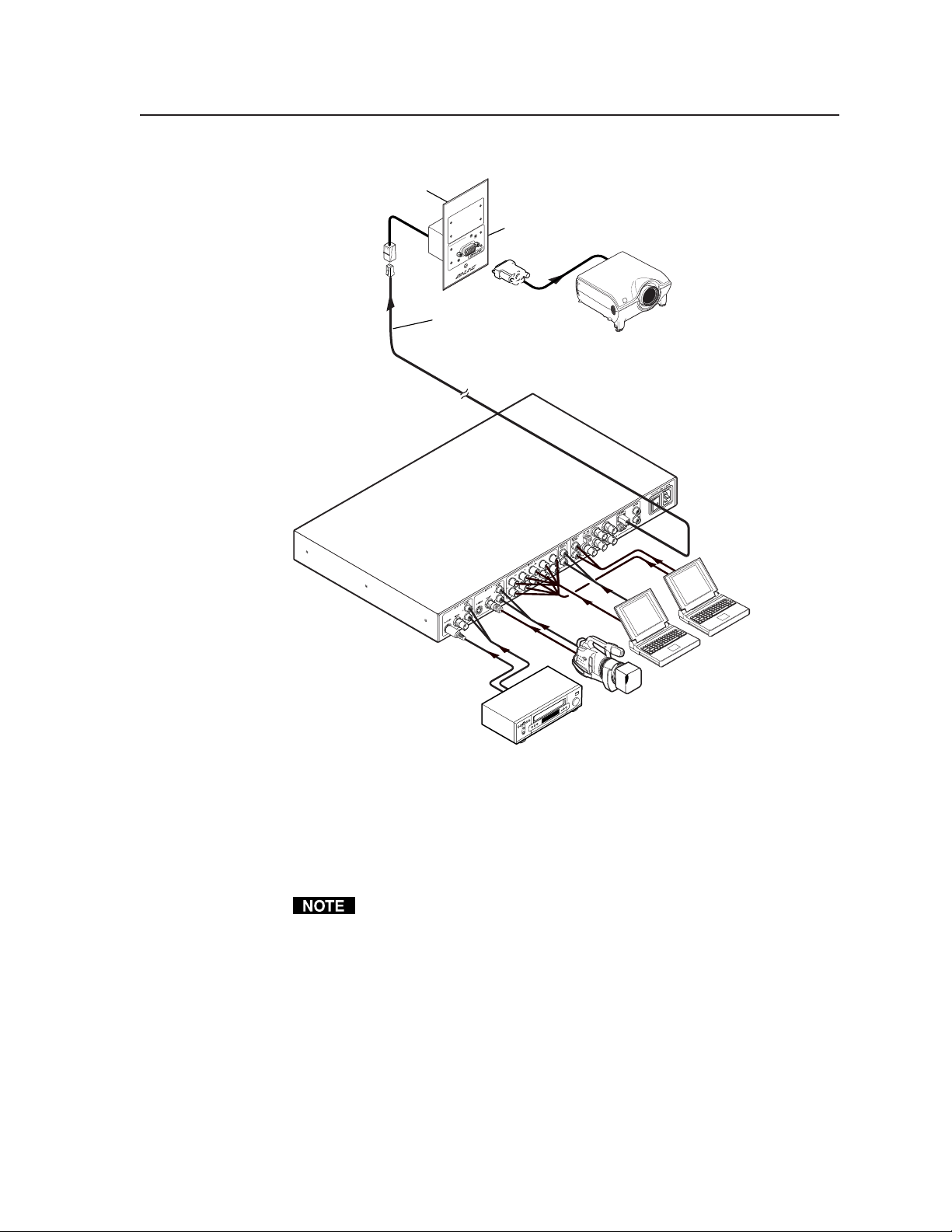
Figure 1-1— Typical IN1404XT Video Scaler and Switcher application
TP transmission
The TP output on the RJ-45 connector and an optional Extron VTR001CM receiver
provide a system for long-distance distribution of computer (RGBHV or RGBS)
video over Extron’s skew-free A/V UTP cable or over CAT 5 unshielded twisted
pair (UTP), shielded twisted pair (STP), or foil shielded twisted pair (FTP) cable.
TP cable advantages
Extron’s skew-free cable or CAT 5 cable is a fraction of the size of coaxial cable, as
well as being much lighter, more flexible, and far less expensive. These TP
products make cable runs simpler and less cumbersome. Termination of the cable
with RJ-45 connectors is simple, quick, and economical.
Video Camera
VCR/DVD
The VTR001CM can receive RGsB signals from the scaler. However, the red,
green, and blue video signals’ black levels are not clamped to a 0V reference, as
for RGBHV or RGBS. For most displays, this is not a problem. On some
displays (such as some LCD displays) however, the black levels of the red,
green, and blue signals may change as the average picture level changes,
resulting in an unacceptable image.
1-3IN1404XT Video Scaler and Switcher • Introduction
Page 10

Introduction, cont’d
Features
Inputs —
Video inputs — The scaler switches among two fully-configurable RGB, HDTV
component video, interlaced component video, progressive scan video,
S-video, or composite video inputs on 5 BNC connectors (inputs 3 and 4); two
S-video inputs on 4-pin mini-DIN connectors (S-video inputs 1 and 2 only);
or composite video inputs on single BNC connectors (composite video inputs
1 and 2).
Audio inputs — The scaler switches among four unbalanced stereo audio inputs
on RCA connectors. Inputs can come from sources such as a VCR, DVD
player, computer audio card, or other audio device that outputs a stereo linelevel signal.
Outputs —
Standard video outputs — The IN1404XT outputs scaled video signals as
progressive RGBHV, RGBS, or RGsB, from 640 x 480 up to 1365 x 1024, to
match the optimum or native resolution of virtually any display device, on
five BNC connectors and a 15-pin HD connector.
The output refresh rate is selectable as desired. When used with LCD or DLA
displays, Extron recommends the 60 Hz setting. Higher output refresh rates
can be used with CRT displays to reduce flicker.
TP video output — The scaler outputs a third video signal encoded into a set of
proprietary analog signals on an RJ-45 connector. The scaler transmits this
output in the same format as Extron’s VTT001CM TP transmitter. An
optional Extron VTR001CM receiver can receive this set of signals and
convert them to a high resolution RGBHV, RGBS, or RGsB output (identical
to the 5-BNC and 15-pin HD output).
Audio outputs — The scaler provides an unbalanced line level signal that is
identical to the input signal. This output can drive any line level compatible
audio unit, or a local device such as powered speakers.
Video output resolutions —
The IN1404XT outputs an image scaled up to the following output resolutions:
• 640 x 480 (VGA) at 60 Hz, 72 Hz, 75 Hz, 85Hz, 96 Hz, 100Hz, and 120 Hz
•
800 x 600 (SVGA) at 60 Hz, 72 Hz, 75 Hz, 85Hz, 96 Hz, 100Hz, and 120 Hz
• 852 x 480 at 60 Hz, 72 Hz, 75 Hz, 85Hz, 96 Hz, 100Hz, and 120 Hz
• 1152 x 864 at 60 Hz, 72 Hz, 75 Hz, and 85Hz
• 1024 x 768 (XGA) at 60 Hz, 72 Hz, 75 Hz, and 85Hz
• 1280 x 720 (HDTV - 720p) at 60 Hz, 72 Hz, 75 Hz, 85Hz, 96 Hz, and 100 Hz
• 1280 x 768 at 56 Hz, 60 Hz, and 65 Hz
• 1280 x 1024 (SXGA) at 60 Hz, 72 Hz, and 75 Hz
• 1365x 768 (wide XGA) at 60 Hz, 72 Hz, 75 Hz, and 85 Hz
• 1365 x 1024 (plasma) at 60 Hz
Advanced motion compensation — Extron’s video processing techniques,
advanced motion prediction and compensation methods treat motion content
Either S-video or composite video, but not both, can be connected to input 1
and to input 2. The two inputs can each be a different video format, but only
one format can be connected to an input.
IN1404XT Video Scaler and Switcher • Introduction1-4
Page 11

and still content with different algorithms to yield high fidelity images that are
free of visible scan lines.
Inverse 3:2 pulldown detection for NTSC for film-originated video material —
This advanced film mode processing feature helps maximize image detail
and sharpness for video sources that originated from film. When film is
converted to NTSC video, the film frame rate has to be matched to the video
frame rate in a process called 3:2 pulldown. Jaggies and other image artifacts
can result if conventional deinterlacing techniques are used on film-source
video. The IN1404XT’s advanced film mode processing recognizes signals
that originated from film. The scaler then applies video processing
algorithms that optimize the conversion of video that was made with the 3:2
pulldown process. This results in richly detailed images with sharply
defined lines.
Quad-standard decoding — The IN1404XT’s video decoder provides accurate
video decoding of composite video and S-video in the NTSC, PAL, SECAM,
and NTSC 4.43 standards. The advanced 3-line adaptive comb filter that
decodes composite video reduces cross-color interference and hanging dots
while maintaining maximum image bandwidth and detail.
Seamless Switching - Input 4, when configured as a passive (unscaled) input,
serves as a time reference for seamless switching. The IN1404XT provides a
seamless transition between scaled inputs on 1, 2, or 3 (RGB, component,
S-video, or composite video) and the passive RGB video on input 4.
Picture controls — A wide variety of picture controls are available for fine picture
adjustments:
• Position
• Size
• Aspect ratio
• Hue
• Saturation
• Brightness and contrast
• Gamma
• Horizontal tracking
• Sharpness
Once these adjustments are made, the settings are stored in non-volatile
memory and automatically recalled when the same input source is selected
again.
Advanced image adjustment controls — A wide variety of picture controls are
available to optimize the image when the scaler is used with proprietary and
non-standard input signals.
Once these adjustments are made, the settings are stored in non-volatile
memory and automatically recalled when the same input source is selected
again.
Blue screen mode — The scaler can be set to output a blue video field, to help
installers calibrate the monitor or projector. Blue screen is always available,
whether or not an input is present or properly adjusted.
On screen menus - The scaler puts its menu displays on the output video stream,
for display by the output monitors or projectors. The menu system provides
easy control of video adjustments including hue, color, contrast, brightness,
1-5IN1404XT Video Scaler and Switcher • Introduction
Page 12

Introduction, cont’d
gamma, sharpness, image size, image position, and edge blanking.
Individual image settings can be optimized and stored for each input. Each
time an input is selected, all image settings stored for that input are
automatically recalled. The on-screen menus also make it easy to verify and
adjust advanced settings such as output signal resolution, refresh rate, sync
format; the RS-232 control options; and the reset to factory defaults function.
A handy System Info menu option uses the on-screen display to show
comprehensive information about the input and output signals and scaler
settings.
Audio follow and breakaway — Audio switching can follow its corresponding
video input signal or, under RS-232 control, audio can be broken away from
the video input.
Except as noted in Video breakaway, below, when a new input channel is
selected, the audio automatically switches to the newly selected input
channel.
Video breakaway — Under RS-232 control, video can be switched without
disturbing the audio switch.
Operational flexibility — Operations such as input and scaling selection, picture
controls, and saving and recalling of presets can be performed on the front
panel or over the RS-232 link. The RS-232 links allow remote control via a PC
or control system.
• Front panel control — The scaler’s front panel controller and on-screen
menus support individual input selection, resolution selection, volume
control, and complete configuration of the scaler.
• ASCII character command set — The remote control protocol uses Extron’s
ASCII character command set for easy programming and operation.
Freeze mode — Provides a high quality still image for applications that require
close examination of a specific video frame. Freeze mode operates for video
and RGB signals that are processed by the scaling circuitry. Passive
(unscaled) video on input 4 cannot be frozen.
Blank mode — Suppresses the output video image. Blank silences the R, G, and B
video outputs but the scaler still outputs sync. This ensures that the output
device does not lose sync lock. Blank mode operates for video and RGB
signals that are processed by the scaling circuitry. Passive (unscaled) video
on input 4 cannot be blanked.
User memories — The IN1404XT provides 128 user memories that store all video,
audio, and input parameters. User memories allow the unit to be optimized
for a large number of sources and gives the capability to recall those settings
quickly. The memories make it easier to add to the number of inputs to the
scaler by putting a switcher in front of an input.
Rack mountable — The 1U high scaler can be mounted in any conventional 19”
wide rack using the included IN9123B rack ears.
Power — The 100VAC to 240VAC, auto-switchable, internal power supply of the
IN1404XT provides worldwide power compatibility.
IN1404XT Video Scaler and Switcher • Introduction1-6
Page 13

IN1404XT Video Scaler and Switcher
Chapter Two
2
Installation
Installation Overview
Mounting the Scaler
Cabling and Rear Panel Views
Configuration
Page 14
Installation, cont’d
Installation
Installation Overview
To install and set up an IN1404XT video scaler and switcher for operation, perform
the following steps:
Disconnect power from all of the equipment, including the video and audio
1
source(s), and the devices that will receive the output video and audio signals.
Ensure the power switch on the scaler is off.
Rack mount the scaler if desired. See Mounting the Scaler in this chapter.
2
Connect the video and audio input cables. See Input connections in this
3
chapter.
Connect the standard video and audio output cables. See Standard output
4
connections in this chapter.
If desired, connect the TP cable between the scaler and an optional VTR001CM
5
TP receiver and connect the output cables from the TP receiver to the display.
See TP output connection in this chapter and refer to the VTT001CM and
VTR001CM - Twisted Pair Transmitter and Receiver manual, part # 68-760-01.
If desired, connect the RS-232 cable. See RS-232 connection in this chapter.
6
Connect the AC power cable. See Power connection in this chapter. Turn on
7
the sources, video and audio destinations, and the scaler.
Configure the scaler’s inputs and configure the output for the optimum
6
image. See chapter 3, Operation and chapter 4, Programmer’s Guide.
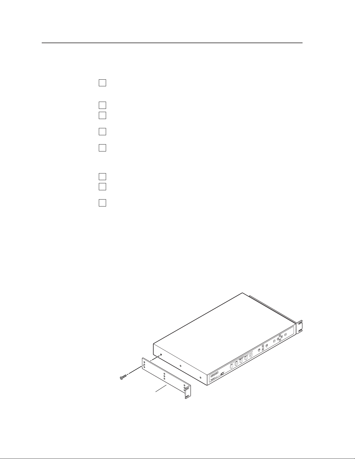
Mounting the Scaler
The scaler includes four installed rubber feet. If you are going to rack mount the
scaler, mount it before cabling it (see Rack mounting, below). The IN1404XT is
exactly 1U high without the rubber feet; if you plan to rack mount the scaler with
other equipment directly underneath it, the feet must be removed.
Rack mounting
Rack mount the scaler as follows:
1. Remove the three enclosure screws on one side of the scaler (figure 2-1).
Rack-mount
Bracket
Figure 2-1 — Mounting the scaler
IN1404XT Video Scaler and Switcher • Installation2-2
Page 15
2. Attach one rack mount bracket to that side of the scaler with three screws
removed in step 1.
3. Repeat steps 1 and 2 on the other side of the scaler.
4. Insert the scaler into the rack, align the holes in the mounting bracket
with those of the rack.
5. Secure the scaler to the rack with machine screws.
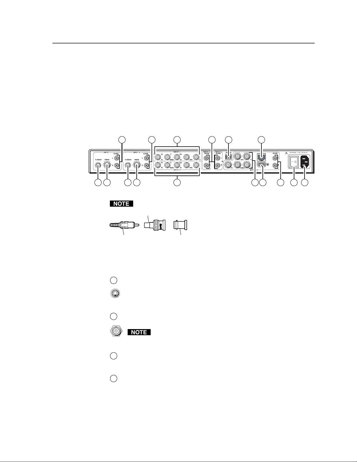
Cabling and Rear Panel Views
All connectors are on the rear panel (figure 2-2).
4 4
1 10111
2 2 63
Figure 2-2 — IN1404XT rear panel connectors and power switch
With the exception of input 1 and 2 S-video, all video input and output
RCA-to-BNC Connector
Input connections
Input 1 and Input 2 S-video connectors — Connect S-video sources to these
1
4-pin mini DIN connectors. If necessary, use an 8” Extron SVHS - BNC
adapter, part #26-353-01.
— Or —
3
4
89
UTP Link
75
connections to the scaler are made with female BNC
connectors. Some types of video output devices do
not have BNC video output connectors. For these
cases, a suitable cable or connector adapter is
BNC ConnectorRCA Connector
necessary between the device output connector and
the BNC input connector of the switcher. The
Extron part number for the RCA-to-BNC adapter
is 10-264-01.
Input 1 and Input 2 composite video connectors — Connect composite video
2
sources to these female BNC connectors.
For input 1 and input 2, video can be connected to either the S-video
input or the composite video input, but not both. If you connect to
both, the scaler will not accept either signal.
Input 3 and Input 4 connectors — Connect computer or RGB video,
3
component video, S-video, or composite video to these female BNC
connectors. Figure 2-3 shows how to connect the various video formats.
Input 1 through Input 4 audio connectors — Connect each unbalanced stereo
4
audio input to these pairs (left and right) of RCA connectors. Computer
sound cards and other devices with a 3.5 mm mini output connector can be
connected using an optional Extron IN9107 3.5 mm stereo mini male to (2)
RCA male cable.
2-3IN1404XT Video Scaler and Switcher • Installation
Page 16
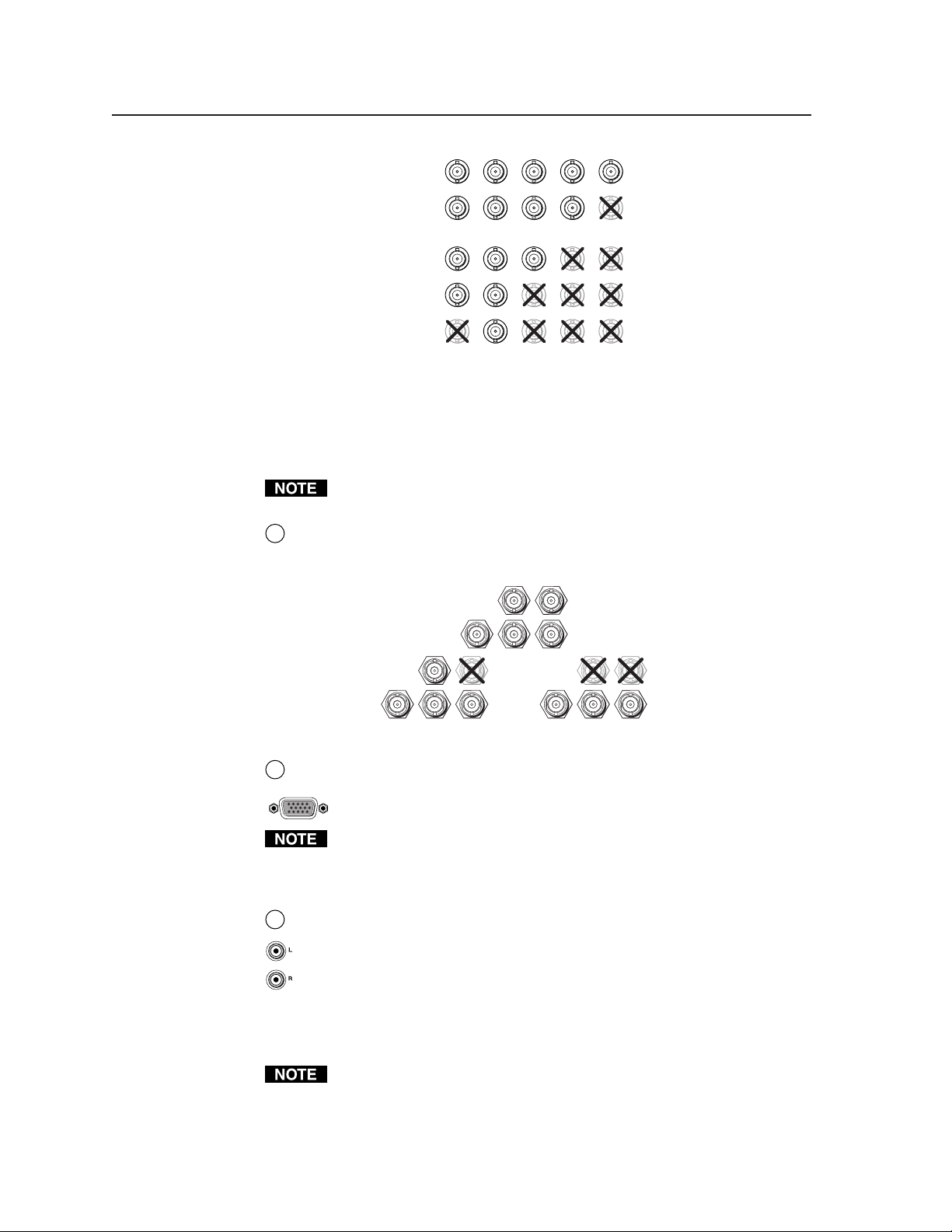
Installation, cont’d
Figure 2-3 — Connections for various input video formats
The audio bass, treble, and balance levels for each input can be individually
set via the front panel or the RS-232 link. See chapter 3, Operation, and
chapter 4, Programmer’s Guide for details.
Standard output connections
Output BNC connectors— Connect an RGBHV, RGBS, or RGsB video display
5
to these female BNC connectors. Figure 2-4 shows how to connect the various
video formats.
Cr
RGBHV
RGBS
RGsB,
Component
S-video
Composite
video
Y
R
G/GsCbBH/S V
CrRY
G/GsCbB H/S V
Cr Y Cb
(R-y) Y (B-Y)
(Pr)RY
Cr
(C)
RYG/GsCbB H/S V
CrRY
(Pb)
G/Gs
B H/S V
(Vid)
G/GsCbB H/S V
The two standard outputs, consisting of five BNC connectors and a 15HD
connector, output the identical video signal and the same sync format.
RGBHV
RGBS
G/Gs
R
Figure 2-4 — BNC output connections for RGBHV and RGBS video
Output 15HD connector — Connect an RGBHV, RGBS, or RGsB video
6
display to this female 15HD connector.
The two standard output connectors, BNCs and 15-pin HD, are individually
buffered (even when input 4 is configured as passive (unscaled). They can
both be simultaneously connected and transmitted up to 100 feet on high
quality coax cable without degradation of either output.
Output audio connectors— Connect an audio device, such as an amplifier or
7
powered speakers, to these left and right RCA connectors.
By default, the audio output follows the video switch. Audio breakaway,
commanded via the RS-232 link, allows you to select from any one of the
audio input sources. See chapter 3, Operation and chapter 4, Programmer’s
Guide for details.
TP video output connection
RJ-45 termination must comply with the TIA/EIA T 568A or TIA/EIA T 568B
wiring standards for all connections.
V
H/S
B
G/Gs
R
V
H/S
RGsB
B
R
H/S
G/Gs
V
B
IN1404XT Video Scaler and Switcher • Installation2-4
Page 17
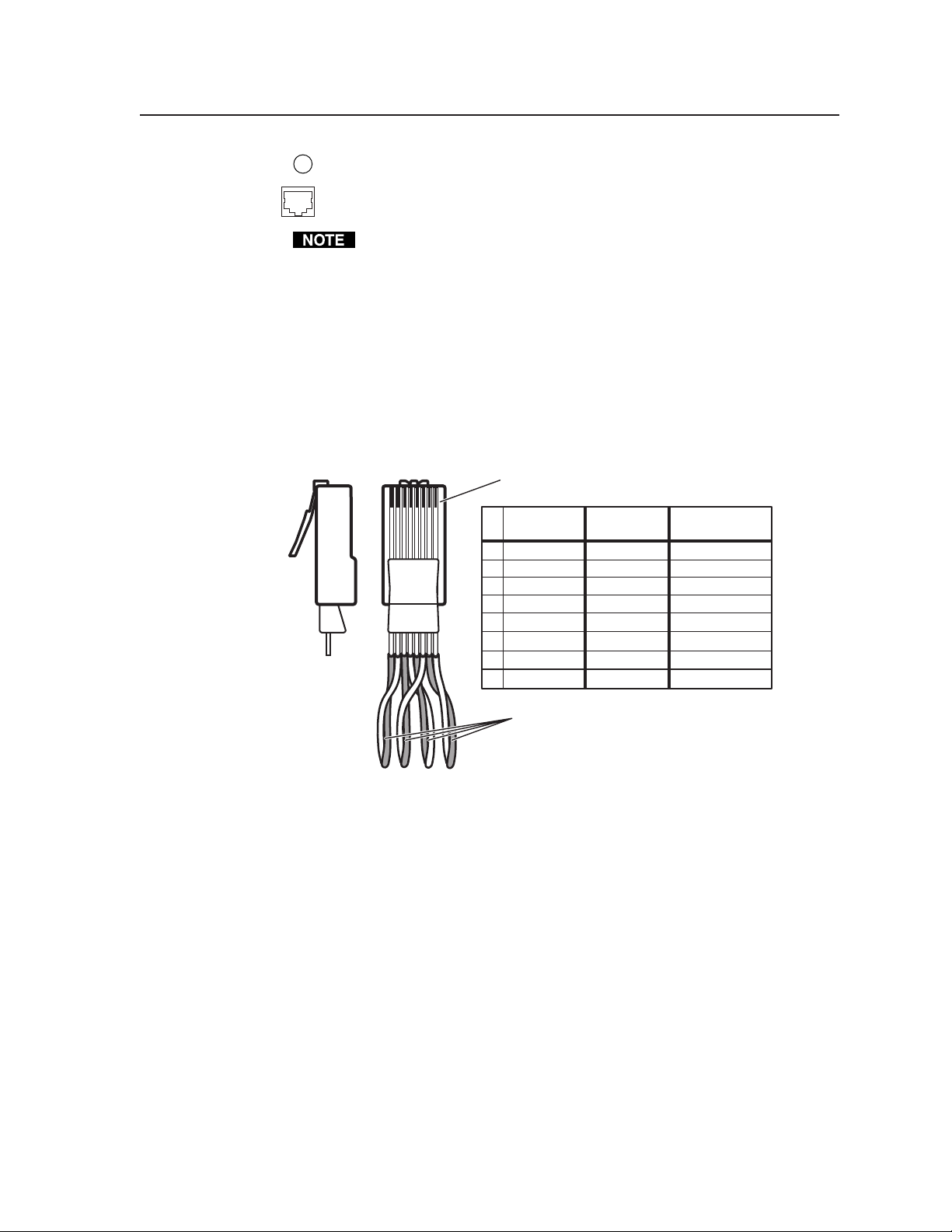
RGB video transmission connector — Connect one end of a TP cable to this
8
RJ-45 female connector. Connect the other end of the TP cable to an optional
Extron VTR001CM or other compatible Extron TP receiver. See Optional
Accessories, in Appendix A, Reference Information, for compatible TP receivers.
The VTR001CM can receive RGBHV and RGSB signals from the scaler with
no loss of image quality. The VTR001 CM can also receive RGsB signals from
the scaler. However, the red, green, and blue video signals’ black levels are not
clamped to a 0V reference, as for RGBHV or RGBS. For most displays, this is
not a problem. On some displays (such as some LCD displays) however, the
black levels of the red, green, and blue signals may change as the average
picture level changes, resulting in an unacceptable image.
Termination of TP cable
Figure 2-5 details the recommended termination of TP cables in accordance with
the TIA/EIA T 568A and TIA/EIA T 568 B wiring standards. You can use either
standard, but ensure you use the same standard on both ends of the cable.
Clip DownSide
12345678
RJ-45 connector
1
2345678
TIA/EIA T-568-A
Pin
Wire color
RGB video signal
1
White-green
2 Green
3
White-orange
4
Blue Green+
White-blue
5
6
Orange
7 White-brown Blue/H. sync+
8
Brown
TIA/EIA T-568-B
Wire color
Red/V. sync+
White-orange
Orange
Red/V. sync-
White-green
Power
Blue
Green-
White-blue
Power
Green
White-brown
Brown
Blue/H. sync-
Twisted Pairs
1&2
7&8
3&6 4&5
Figure 2-5 — TP cable termination
Cable testing
To ensure proper cable termination, each transmission cable system that uses CAT 5
cable should be tested (Extron’s skew-free UTP cable does not need to be tested).
Testing the cable from the RJ-45 connections at the transmitter and receiver gives
the most accurate indications of cable problems.
There are two varieties of cable runs: simple runs, in which a single cable is
terminated only at the transmitter and receiver, and complex runs, which can
include patch bays and multiple terminations and lengths of cable. In either case,
the entire cabling system should be tested.
A complete test measures cable length and tests the wire map, attenuation, NEXT,
PSNEXT, ELFEXT, PSELFEXT, return loss, ACR and PSACR. All of these tests are
critical for digital data transfer, but not for analog video. While all of these tests are
important indicators of the quality of the cable termination, the most critical testing
parameters for video transfer are wire map (T-568-A or B termination) and pair
length measurements. The largest concern is equalization of skew between cable
pairs. Cable systems of 300 feet or less should exhibit no transmission problems if
they pass at least CAT 5 channel certification testing.
2-5IN1404XT Video Scaler and Switcher • Installation
Page 18

Installation, cont’d
The Microtest OMNI SCANNER 2 performs comprehensive certification testing to
the proposed CAT 6 standards. Other manufacturers also make testing equipment.
The tests include advanced diagnostics for troubleshooting the cause and location
of many cable and termination problems. For simple installation testing, the
Microtest MICRO SCANNER PRO tests wire map and cable length, including
individual cable pair length.
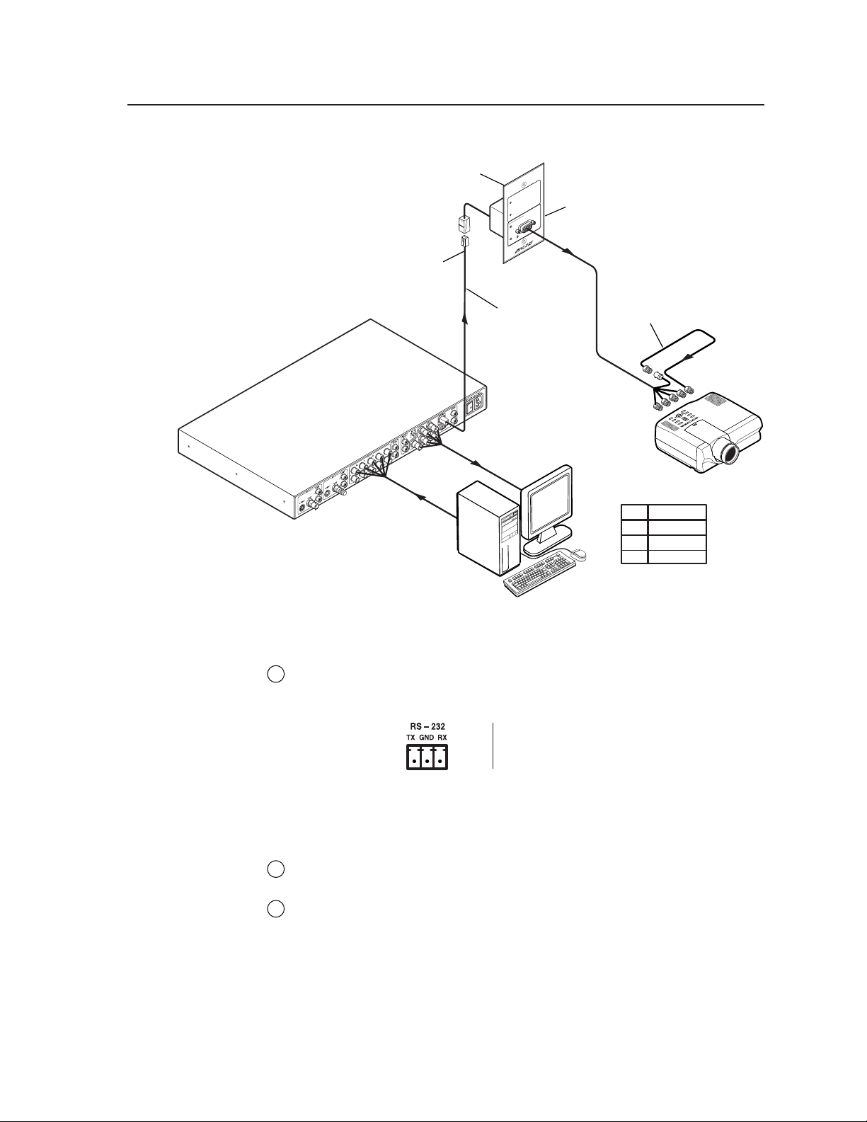
Equalizing pair skew
The manufacturing process for network (CAT 5) UTP cable leads to a condition
called pair skew. For best results, pair skew needs to be equalized when using the
CAT 5 cable in A/V applications. The design of Extron’s skew-free A/V UTP cable
minimizes pair skew to the point that equalization is not required.
Skew exists between pairs when the physical length of one wire pair is different
from another. As the transmission cable length increases, the amount of skew
increases. Skew affects the displayed image when the differential length between
wire pairs exceeds 2 feet, causing the timing of the red, green, and blue video
signals to appear out of alignment (horizontal registration errors). A white vertical
line on a black field can appear as individual red, green, and blue lines that are
close together; the signal transmitted on the shortest wire pair leads the other colors
and appears to the left on the display.
UTP cable test equipment measures and reports wire pair length. The report on the
various pair lengths can be used in equalizing pair skew. The nominal velocity of
propagation (NVP — the speed at which the signal travels on the transmission line,
measured as a percentage of the speed of light) of TP cable is very close to that of
conventional coaxial cable. The similarity in NVP means that:
• by using an Extron IN9045-L6 15HD male-to-5 BNC male, 6’ cable, to adapt
the output on a 15HD connector to BNC connectors,
• and then adding an additional length of coax equal to the length of pair skew,
placed on the receiver’s output,
you can equalize the effects of pair skew (figure 2-6).
If UTP cable test measurement cannot be done, pair skew can still be equalized by
viewing a test pattern with a critical eye. Examine the test pattern for loss of
horizontal registration and, through a process of trial and error, equalize any pair
skew with coax extensions on the red, green, and/or blue outputs.
Extron skew compensation coax cables are available in lengths of 2 through 20 feet,
see Appendix A, Reference Information, for part numbers.
IN1404XT Video Scaler and Switcher • Installation2-6
Page 19
Extron CPM101
Connector Panel
Extron
IN1404XT
Video/RGB Scaler
CAT 5 UTP Cable
Extron
T
PU
VTT001CM
VIDEO IN
Twisted Pair Receiver
IF cable measurement
indicates that the pair
with wires
four feet shorter than
the other signals...
Twisted Pair Receiver
1 and 2
is
VTR001
... THEN insert a 15HD-to-BNC
extension cable and a four-foot
skew compensation cable to
equalize UTP skew for red video.
Projector
Pair RGB video
1, 2
Red
4, 5
Green
7, 8
Blue
Figure 2-6 — Pair skew equalization
RS-232 connection
RS-232 port — Connect a host device, such as a computer, RS-232 capable
9
PDA, or third-part control system, to the scaler via this 3.5 mm, 3-pole captive
screw connector for serial RS-232 control (figure 2-7).
Figure 2-7 — RS232 port pin assignments
See chapter 4, Programmer’s Guide, for definitions of the ASCII command set.
Power connection
AC power connector — Plug a standard IEC power cord between this
10
connector and a 100 to 240VAC, 50 Hz or 60 Hz power source.
Power switch — Turn the power switch on. The front panel LEDs flash twice
11
during power-up and then all but the LED for the previously selected input
go out.
Configuration
The IN1404XT can be configured using either the front panel controls or the ASCII
command set. See chapter 3, Operation and chapter 4, Programmer’s Guide.
TX
Gnd
RX
FunctionPin
Transmit data
Signal ground
Receive data
2-7IN1404XT Video Scaler and Switcher • Installation
Page 20

Installation, cont’d
IN1404XT Video Scaler and Switcher • Installation2-8
Page 21

IN1404XT Video Scaler and Switcher
Chapter Three
3
Operation
Front Panel Controls and Indicators
Front Panel Operations
Optimizing the Video
Optimizing the Audio
Troubleshooting
Page 22
Operation, cont’d
Operation
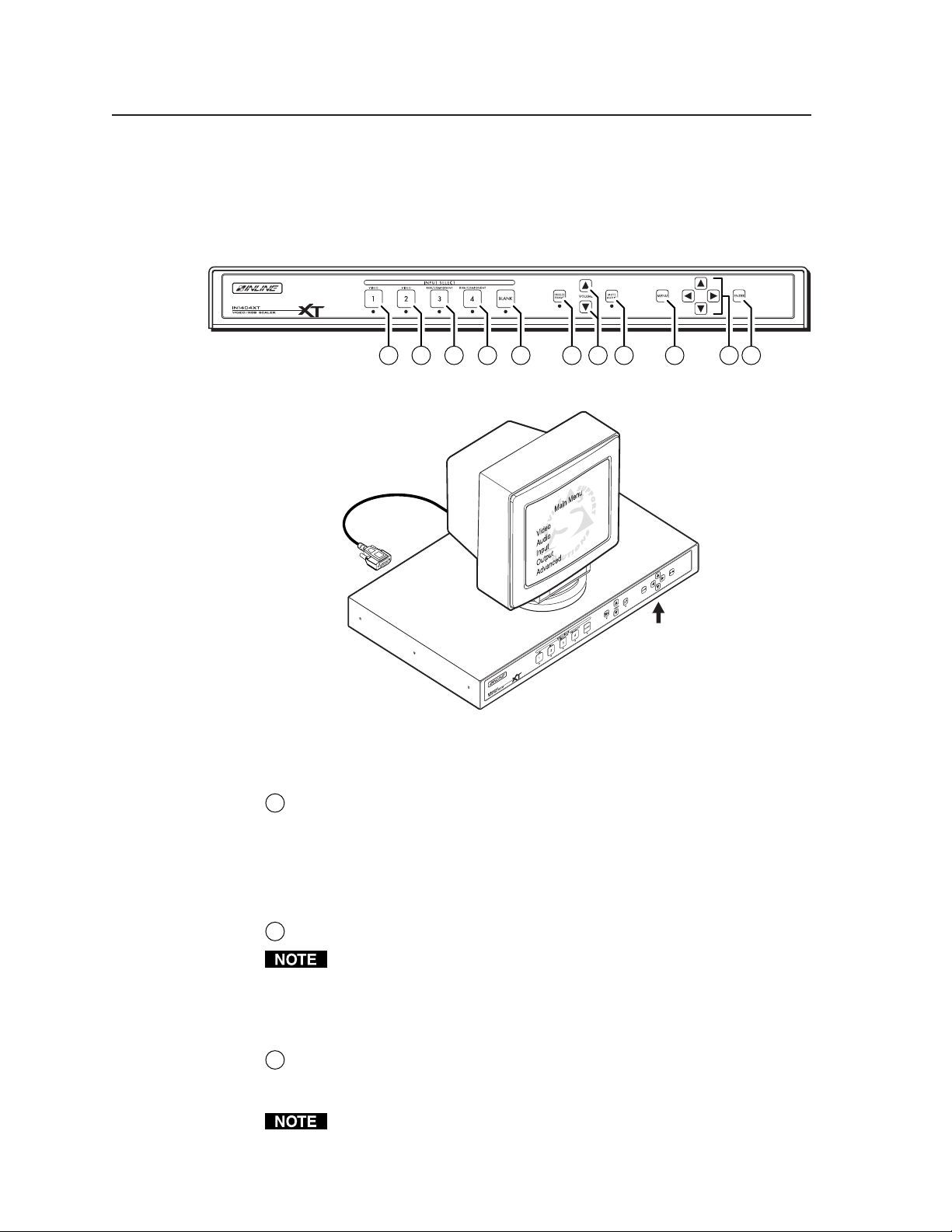
Front Panel Controls and Indicators
All of the scaler’s controls are on the front panel (figure 3-1). Front panel LEDs
provide graphic indication of some of the basic system functions. For more
complex tasks, such as system configuration, the scaler has a menu system that is
operated using the front panel buttons and displayed on the output monitors
(figure 3-2).
Figure 3-1 — IN1404XT video scaler and switcher front panel
1 1 1 1 2 3 4 5 86 7
Figure 3-2 — Menu system display
Video controls
Input 1 through 4 buttons — The Input 1 through Input 4 buttons select the
1
associated video input to scale (except for input 4 when configured as
passive) and display on the output(s). Audio follows (switches with) the front
panel video selection.
Input 1 through 4 LEDs — The lit Input 1 through Input 4 LED indicates the
video and audio input that is selected.
Blank button — The Blank button switches the output(s) to a black screen.
2
15HD
Menu Controls
Blank turns off the R, G, and B video output signals only; the H and V sync
outputs remain active. This ensures that the display(s) retains sync lock.
Blank has no affect on input 4 when it is passive (unscaled).
Blank LED — The Blank LED indicates that the video output is blanked.
Freeze button — The Freeze button locks the output display to the current
3
image being input. When the freeze function is enabled, the Freeze LED is lit.
To unfreeze the image, press the Freeze button again.
When the output is frozen, the video input cannot be removed without losing
the displayed image.
IN1404XT Video Scaler and Switcher • Operation3-2
Page 23
If a different input is selected, see 1, the switching action deselects the freeze
Enter
15 sec.
40
3
3
15 sec.
at iospect
esolARuion
R
t
os i t i o
izePS
n
Mo eam l e ssSe d
lueBSreenc
atnc ForSy m
pu tutO
Menu
Enter
(save)
Menu or
Enter
(save)
VnPos i t i—o
nPos i t iH
—
o
No
menu
display
function, the frozen image is lost, and the Freeze LED returns to its unlit state.
Audio controls
Volume and buttons — The Volume buttons regulate the volume level of
4
the selected audio input. Use the Volume buttons to increase and decrease
the audio level for the current input. Press and release a button to raise or
lower the volume level by one step, or press and hold a button to change the
level continuously. The on-screen display (figure 3-3) shows a quantitative
volume measurement for 15 seconds.
Freeze has no affect on input 4 when it is passive (unscaled).
The IN1404XT automatically saves the volume levels for each input. This is
the only adjustment that does not need to be saved by pressing the Enter
button.
display
Figure 3-3 — Volume on-screen display
Mute button — The Mute button mutes the audio output.
5
Mute LED — The Mute LED indicates that the audio output is muted.
Menu control buttons
Menu button — The Menu button enters and backs out of the main menu
6
system in the IN1404XT. See Front Panel Operations in this chapter for details.
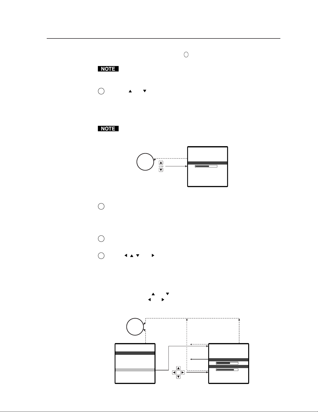
Menu , , , and buttons — The Menu buttons navigate the main menu
7
main menu system. See Front Panel Operations in this chapter for details.
If you aren’t in the menu system, pressing any of these buttons causes the
scaler to display the Position screen (figure 3-4) on the output monitors. The
screen features two status indicators that show the horizontal and vertical
position settings. The position adjustments move the output image on the
monitor. Press the
screen. Press the and buttons to shift the display horizontally on the
screen. Press the Enter button to save the changes and return to normal
system operations.
No
menu
15 sec.
olumeV
40
and buttons to shift the display vertically on the
Figure 3-4 — Horizontal and vertical position on-screen display
3-3IN1404XT Video Scaler and Switcher • Operation
Page 24
Operation, cont’d
Enter button — The Enter button either activates a submenu or function in
8
the IN1404XT menu system or saves a changed value. See Front Panel
Operations in this chapter for details.
Front Panel Operations
The following paragraphs detail the power-up process and then describe the menu
system, the picture adjustments, and selection of executive mode.
Power
Power is applied when the power cord is connected to an AC source and the rear
panel Power (
the scaler performs a self-test that blinks all of the front panel LEDs twice and then
defaults to indicating the selected input. An error-free power up self-test sequence
leaves all of the LEDs, with the exception of the selected input’s LED, off. If Blank
or Mute Audio were selected when the scaler was powered down, those LEDs light
too on power up.
The selected input, the picture adjustments, and other current settings are saved in
non-volatile memory. When power is applied, the latest configuration is retrieved.
The effects of all adjustments are visible on the screen or audible on the audio
output, but they are temporary unless saved. The adjustments return to their
previous settings when the adjustment screen exits by either a timeout or the
operator pressing the Menu button. For a setting that you have made to
become permanent (until replaced in favor of a newer setting), it must be
saved by pressing the Enter button. With the exception of the volume
adjustment (see item
Enter button, your adjustment is lost.
/ ) switch is set to the on ( ) position. When AC power is applied,
4
, above), if you do not save the value by pressing the
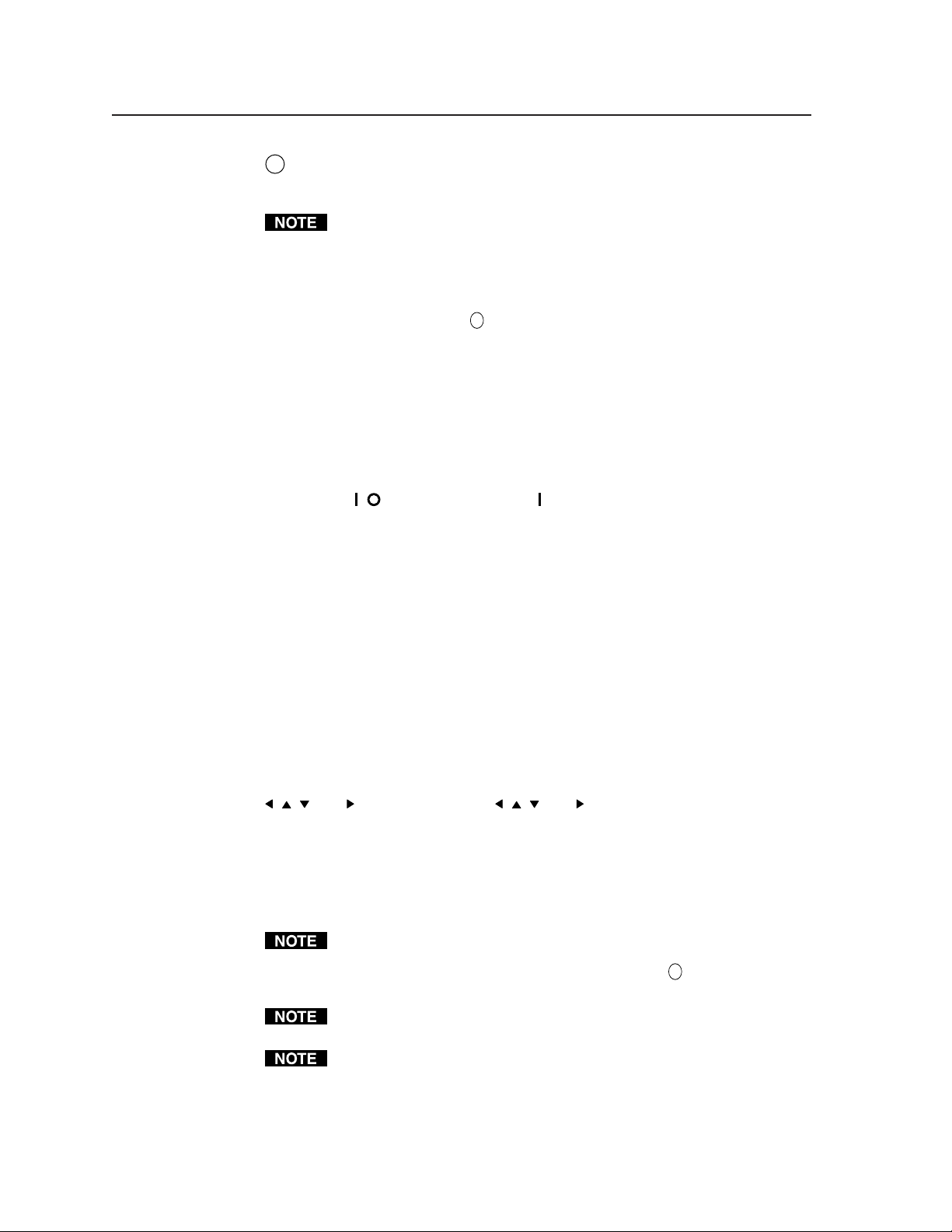
Menu operation
Figure 3-5 shows a flowchart of the main menus in the menu system. Each menu
leads to a series of submenus that accomplish individual tasks or groups of tasks.
Menu button — Press the Menu button to activate the menu system or to back up
one level from the currently selected menu or submenu (for example, pressing
the Menu button in the Video submenu returns the scaler to the Main menu).
, , , and buttons — Press the , , , and buttons to move the highlight bar
over submenus or selections.
Enter button — Press the Enter button to select a highlighted submenu or selection.
Press the Enter button to save a value that you have set to memory. On the
menu system flowcharts (figure 3-7, figure 3-8, figure 3-9, figure 3-11, figure 312, and figure 3-13) and in the following descriptions, “save” functions of the
Enter button are shown in a bold, italics font: Enter (and save).
For a setting that you have made to become permanent (until replaced in favor
of a newer setting), it must be saved by pressing the Enter (and save) button.
With the exception of the volume adjustment (see item
the value by pressing the Enter (and save) button, your adjustment is lost.
To exit an adjustment screen without saving the change, press the Menu
button to return to the previously selected screen.
To return to normal operation (no menus), let the scaler remain idle for 15
seconds until the selected screen times out, or press the Menu button
repeatedly until the Main Menu is deselected.
4
), if you do not save
IN1404XT Video Scaler and Switcher • Operation3-4
Page 25
No
menu
display
Menu
Menu or
15 sec.
Menu
15 sec.
deoVi
righ
Btess
n
ont ras
C
t
✫
BGainRG
olorHC aturaS
✝
ue
arpnesSh s
✝
mm
aNG
a
mb / T r aCo p
esetRideoV
ito
✝
✝
i
lteroise F
✝
15 sec.
Menu
✝
n
esolRRuiont
izePS
os i t i o
lueBSreenc
pu tutO
❖
Ra t eefresh
Mo eam l e ssSe d
n
atnc ForSy m
tputeset ORu
in MenMa u
ideo
V
ud i o
A
pu tIn
utpu
Ot
dvance
A
d
Enter
Menu
dioAu
assTB
reble
lanceBa
ioset AuRe d
pu tIn
igna
SlFor
spect
A
nputHIabe
asePh
dvanRAcd
t
ma
at io
R
ch ngto SwiAu t i
lsL
ack i ngor iz T
r
✫
e
pu tese t I
n
15 sec.
15 sec.
✝
Figure 3-5 — Menu system flowchart
To enable seamless switching, input 4 must be configured as RGB passive
(unscaled) on the Signal Format screen. However, once it is configured as
passive and if input 4 is selected, on-screen menus are not displayed.
No video adjustments are available for the input 4 video signal when it is
configured as passive (unscaled) but audio and other input variables are still
adjustable. Because on-screen displays will be blanked for input 4 once it is
configured as passive, it will be helpful to configure all of the input 4 options
before you configure the input as passive. If, later, you need to change any of
the input 4 settings, the easiest way is to temporarily set input 4 to one of the
scaled output settings. See Signal Format screen in this chapter.
Alternatively, you can make the adjustments under RS-232 control.
MenuMenu
This selection is only available for:
✻ Composite video
✻
✝
✝ Interlaced component, S-video, composite video
✫
✫ RGBHV, RGBS, RGsB, and progresive component
❖
Inputs 3 and 4. Passive input 4 only
❖
●
The refresh rates that are available depend on the
current resolution.
anceddvA
acto
FrRemsey
ser Me
U
ud RatBa e
el im
Deers
R
t
ory
t
-232ese t R
S
fostem ISy n
15 sec.
Status indicators
Most of the Video and Audio menus (see Video menu and Audio menu in this
chapter) and a select few Output menu operations (see Output menu in this chapter)
are performed using on-screen status indicators (figure 3-6) that resemble slide bars
but are controlled using the Menu and buttons.
ont r as tC
128
Figure 3-6 — Typical status indicator
Unless shown in the Video menu and Audio menu subparagraphs, adjusting the
Video and Audio menu settings is accomplished as follows:
1. For the Video, Audio, and Input menu screens, select the input that you want
to adjust by pressing that Input button.
3-5IN1404XT Video Scaler and Switcher • Operation
Page 26

Operation, cont’d
2. Press the Menu button. The on-screen Main Menu display appears on the
connected monitors, overlaid on top of the output image.
3. Use the Menu
Main menu (such as Video) and press the Enter button. The selected
submenu appears on the connected monitors.
4. Use the Menu
submenu (such as Brightness) and press the Enter button. The selected status
indicator appears on the on-screen monitor.
5. Press and release the
level by 1 step or press and hold the buttons to flow through the adjustment
range.
6. Press the Enter (and save) button to save the adjusted value.
To make another adjustment to the same input, return to step 2 or 3.
To adjust another input, exit the menu system by letting the scaler remain idle for
15 seconds until the selected screen times out, or press the Menu button repeatedly
until the Main Menu is deselected and then return to step 1.
Menu system
The main menu selections and their functions are:
and buttons to highlight the desired menu option on the
and buttons to highlight the desired option on the selected
and buttons to decrease and increase the selected
• Video menu — Changes the input signal parameters
• Audio menu — Changes the input signal audio parameters
• Input menu — Changes the input signal parameters
• Output menu — Changes the output signal parameters
• Advanced menu — Displays advanced options
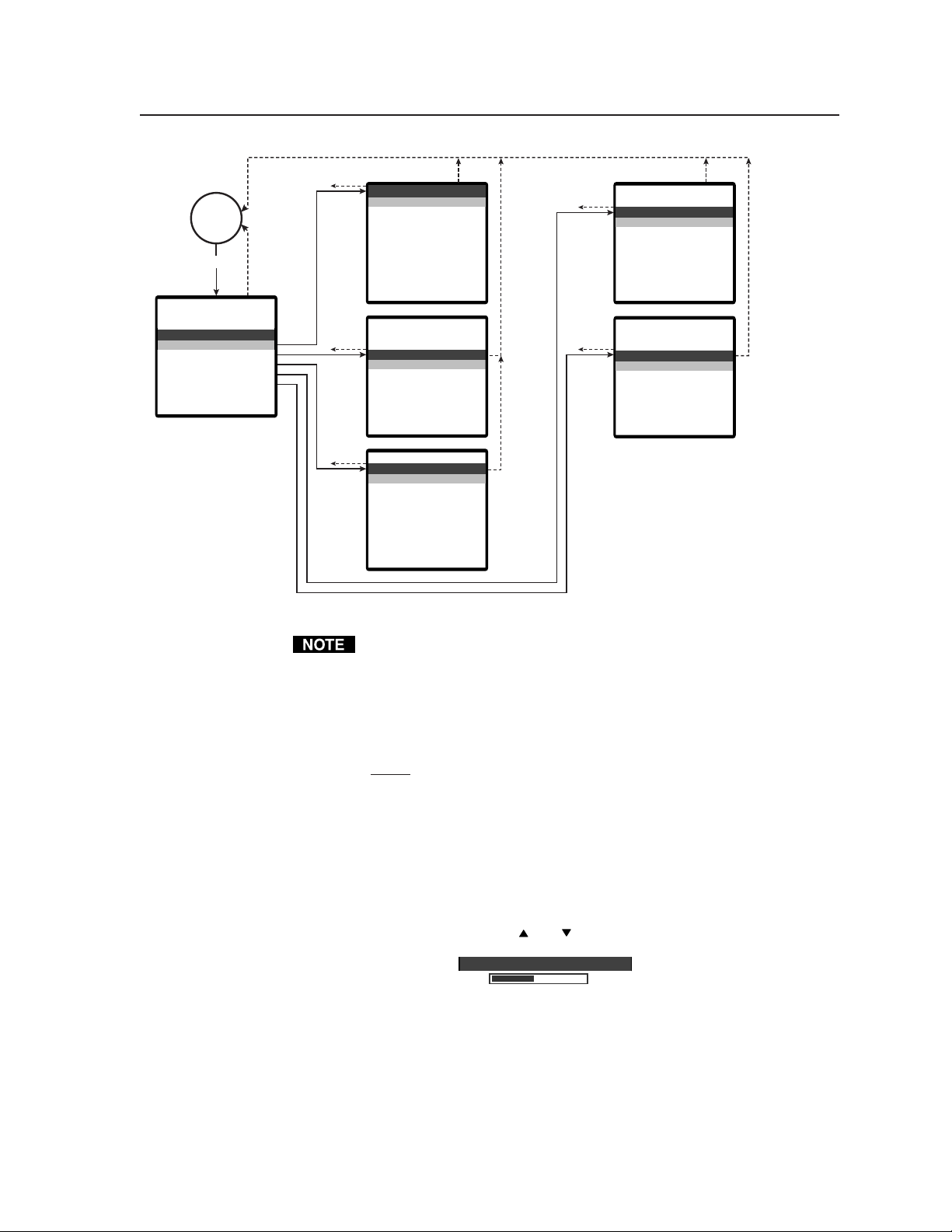
Video menu
Figure 3-7 is a flowchart that shows an overview of the Video menu, its submenus,
and their available settings.
No video adjustments are available for the input 4 video signal when it is
configured as passive (unscaled).
Brightness screen
The Brightness screen displays a status indicator that shows the brightness setting
for the selected input. Brightness adjusts the brightness of the image on the screen.
Use the Menu
to 255. The default setting is 128.
Contrast screen
The Contrast screen displays a status indicator that shows the contrast setting for
the selected input. Contrast adjusts the difference between the input signals
brightness and darkest settings. Use the Menu
contrast through a range of 0 to 255. At the minimum setting, 0, the entire picture is
shown at about the same brightness (gray). At the maximum setting, 255, there is a
marked difference between the dark and light areas of the image. The default
setting is 128.
and buttons to adjust the brightness control through a range of 0
and buttons to adjust the
IN1404XT Video Scaler and Switcher • Operation3-6
Page 27

Menu
15 sec.
15 sec.15 sec.
15 sec.
Menu
No
menu
display
deoVi
righ
Btess
n
ont ras
C
t
✫
BGainRG
olor
C aturaS
✝
ue
H
arpnesSh s
✝
mm
aNG
a
mb / T r aCo p
esetRideoV
ito
✝
✝
i
lteroise F
✝
15 sec.
✝
n
Enter
Enter
(save)
Menu
Enter
(save)
Menu
Menu
Enter
(save)
edR
Green
ueBl
ont r as tC
BGainRG
srightneBs
128
128
✫
✝
ionur tlor SaCo t a
128
Menu
Enter
Enter
(save)
Enter
(save)
Menu
Enter
(save)
Menu
edR
128
Enter
(save)
Menu
Enter
(save)
Comb
Trap
➔
✝
sharpneSs
✝
mm
Ga a
e
tois FiNlre
mb / T r aCo p
3
10
✝
9
✝
Menu
Enter
(save)
✝
eHu
128
Figure 3-7 — Video menu flowchart
Menu
Enter
(save)
se V deRe ito
Yes No
This selection is only available for:
✻ Composite video
✻
✝
✝ Interlaced component, S-video, composite video
✫
✫ RGBHV, RGBS, RGsB, and progresive component
❖
Inputs 3 and 4. Passive input 4 only
❖
●
The refresh rates that are available depend on the
current resolution.
3-7IN1404XT Video Scaler and Switcher • Operation
Page 28

Operation, cont’d
RGB Gain screen
The red, green, and blue gain screens display a status indicator that shows the
input signal gain (contrast) setting for each individual color. Use the Menu
buttons to adjust each color’s gain control through a range of 0 to 255. The default
setting is 128.
An extra step is required to adjust the display, as follows:
1. Select the RGB Gain screen (see steps 1 through 4 in Status indicators in this
chapter).
2. Use the Menu
Red) and press the Enter button. The selected color’s gain status indicator
appears on the on-screen monitor.
3. Press and release the Menu
selected level by 1 step or press and hold the buttons to flow through the
adjustment range.
4. Press the Enter (and save) button to save the adjusted value.
Color Saturation screen
The Color Saturation screen displays a status indicator that shows the color
saturation setting. Color saturation increases and decreases the color of the picture.
Use the Menu
of 0 to 255. At the minimum setting, 0, the scaler removes most of the color. The
default setting is 128.
The RGB gain adjustment is available for RGBHV, RGBS, RGsB, and
progressive component video inputs only.
and
and buttons to highlight the desired color option (such as
and buttons to decrease and increase the
The color saturation adjustment is available for interlaced component video,
S-video, and composite video inputs only.
and buttons to adjust the color saturation control through a range
Hue screen
The hue adjustment is available for NTSC interlaced component video,
S-video, and composite video inputs only.
The Hue screen displays a status indicator that shows the hue setting. Hue adjusts
the picture’s color toward red or green. Use the Menu
color saturation control through a range of 0 to 255. Press the Menu button to
increase the green (and decrease the red). Press the Menu button to increase the
red (and decrease the green). The default setting is 128.
Sharpness screen
The sharpness filters are available for interlaced component video, S-video, and
composite video inputs only.
The Sharpness screen displays a status indicator that shows the sharpness setting.
Sharpness uses variable filtering to affect input picture detail and definition. Use
the Menu
range of 0 to 8. The default setting is 3.
and buttons to increase or decrease the sharpness filtering through a
Increasing the sharpness gives the visual affect of decreasing the noise filter
setting (see Noise filter screen in this chapter). Although the two filters
appear to counteract each other, the two adjustments are completely separate.
Adjust both settings for optimum picture quality.
and buttons to adjust the
IN1404XT Video Scaler and Switcher • Operation3-8
Page 29

Gamma screen
The gamma filters are available for interlaced component video, S-video, and
composite video inputs only.
The Gamma screen displays a status indicator that shows the selected gamma filter.
The scaler has 30 programmed gamma filters that compensate for the non-linear
response of many display devices. Use the Menu
or higher-numbered gamma curves through a range of 1 to 30. The default setting
is 10, which selects a gamma correction curve of 1.0.
For best results, before selecting the gamma filter, set the brightness and
contrast controls to their factory default settings of 128 (see Brightness
screen and Contrast screen in this chapter). Once the optimum gamma filter
is selected, fine tune the output with the brightness and contrast controls.
Noise Filter screen
The noise filters are available for interlaced component video, S-video, and
composite video inputs only.
The Noise Filter screen displays a status indicator that shows the selected noise
filter. Use the Menu
filters through a range of 0 to 47. The default setting is 9.
Increasing the noise filter setting gives the visual affect of decreasing the
sharpness (see Sharpness screen in this chapter). Although the two filters
appear to counteract each other, the two adjustments are completely separate.
Adjust both settings for optimum picture quality.
Comb/Trap selection screen
The Comb/Trap selection screen is available for composite video inputs only.
The Comb/Trap selection screen displays the currently selected Y/C separation
filter (comb filter or trap filter) and provides the ability to change the unselected
filter. The selected filter is indicated by an arrow (➔).
To change the selected filter, use the Menu
filter and press the Enter (and save) button. In general, the trap filter is the better
setting when scaling composite video from a VCR, but try both filters to determine
which is best for your application.
and buttons to step to lower- or higher-numbered noise
and buttons to step to lower-
or button to highlight the desired
Reset Video screen
The Reset Video screen provides the ability to reset all of the video settings for the
selected input to the factory defaults. Use the Menu
and press the Enter (and save) button to reset the video input. Use the button to
highlight “No” and press the Enter button to exit the screen without resetting the
video input (or back out of the screen by pressing the Menu button).
button to highlight “Yes”
Audio menu
Figure 3-8 is a flowchart that shows an overview of the Audio menu, its submenus,
and their available settings.
Bass screen
The Bass screen displays a status indicator that shows the bass setting for the
selected input. Bass enhances or attenuates the lower frequencies of the audio
signal. Use the Menu
through a range of 6 to 27. The default setting is 16 (0dB, no gain or attenuation).
and buttons to increase or decrease the lower frequencies
3-9IN1404XT Video Scaler and Switcher • Operation
Page 30

Operation, cont’d
15 sec.
15 sec.
Menu
assTB
reble
lanceBa
No
menu
display
dioAu
Enter
(save)
Menu
Enter
(save)
15 sec.
Enter
Menu
ioset AuRe d
Enter
(save)
Menu
Enter
(save)
assB
16
rebleT
16
ealancB
16
se A d iRe uto
Yes No
Figure 3-8 — Audio menu flowchart
Treble screen
The Treble screen displays a status indicator that shows the treble setting for the
selected input. Treble enhances or attenuates the higher frequencies of the audio
signal. Use the Menu
and buttons to increase or decrease the higher
frequencies
through a range of 8 to 25. The default setting is 16 (0dB, no gain or attenuation).
Balance screen
The Balance screen displays a status indicator that shows the balance setting for the
selected input. Balance shifts the stereo audio signal to the left or right channel in
incremental steps. Use the Menu
(left) and (right) buttons to shift the audio to
the left and right through a range of 0 to 31. The default setting is 16 (audio in the
center).
Reset Audio screen
The Reset Audio screen provides the ability to reset all of the audio settings for the
selected input to the factory defaults. Use the Menu
button to highlight “Yes”
and press the Enter (and save) button to reset the audio input. Use the button to
highlight “No” and press the Enter button to exit the screen without resetting the
audio input (or back out of the screen by pressing the Menu button).
IN1404XT Video Scaler and Switcher • Operation3-10
Page 31

Input menu
Figure 3-9 is a flowchart that shows an overview of the Input menu, its submenus,
and their available settings.
Menu
.Co3monenp
.RGBH4V
Conn e t on lc
signaI
15 sec.
tignaSlForma
site.Comp1o
oS-Vid2. e
❖
y1
Fo rma t
in ut.oeachtp
❖
t
lraecI-nt
Menu
Enter
Enter
(save)
Com
Com oneonp
➔
RGBHV
RGB S
RG B
RG Bssv Pssi ea
15 sec.
nputI4
sitepo
oS-Vide
t
lrae
I-nt
nen t -Pr oComp
❖
❖
❖
ersg
❖
v Pssi eRGBHVS a
❖
Menu
❖
c
e
❖
s
vdi
Enter
(save)
➔
Fas t
No r a lm
Sl w
o
15 sec.15 sec.
15 sec.
✝
gnor izHrackiT
Fas tVe r y
No
menu
display
15 sec.
pu tIn
igna
SlFor
spect
A
nputHIabe
asePh
dvan
Acd
R
t
ma
at io
R
w
iAu t i
ch ngto S
lsL
✝
ack i ngor iz T
r
✫
e
pu tese t I
n
Enter
Menu
Enter
(save)
Menu
Enter
(save)
Menu
Enter
(save)
specAtRatio
➔
ardStand
ph c
Anamor i
W
W
➔
Of f
On
Mom n t atrye
id scrreee
ie
d
nputIabelsL
s
n
Sc r een
m
aTomara
Label sRe e
hito S i tAu w c ng
FFOON
Menu
Enter
Enter
(save)
Menu
Enter
(save)
Menu
Enter
(save)
To t l P i xa
Sc n
a
Menu
Enter
(save)
Yes No
lse abRe Lte
This selection only available for:
✻ Composite video
✻
✝
✝ Interlaced component, S-video, composite video
✫
✫ RGBHV, RGBS, RGsB, and progresive component
❖
Inputs 3 and 4. Passive input 4 only
❖
● The refresh rates that are available depend on the
current resolution.
dvanAcde
eAreaAct i v
ngBlanki
Type
Mo eInput d
haseP
✫
les
✫
✫
✫
tse npRe Itu
oYes N
10
Figure 3-9 — Input menu flowchart
3-11IN1404XT Video Scaler and Switcher • Operation
Page 32

Operation, cont’d
Signal Format screen
The Signal Format screen shows the video format (such as RGBHV, component
video, or S-video) assigned to each input and provides the ability to change the
video format assigned to each input.
Change the input video format as follows:
It is critical that the signal format selected is correct. If the wrong input
circuitry is selected for the input signal, the scaler will not function properly
and will display either a distorted image or no image at all.
To enable seamless switching, input 4 must be configured as passive
(unscaled) on the Signal Format screen. However, once it is configured as
passive and if input 4 is selected, the scaler cannot place the on-screen displays
on the output video stream.
No video adjustments are available for the input 4 video signal when it is
configured as passive (unscaled) but audio and other input variables are still
adjustable. It is helpful, therefore, to configure all of the input 4 options
before you configure input 4 as passive. If, later, you need to change any of
the input 4 settings, the easiest way is to temporarily set input 4 to one of the
scaled output settings.
The signal format is the only input variable that you can change when that
input is not selected. By selecting an input other than input 4
the Menu button, you
from passive (all on-screen displays blanked for input 4) to one of the scaled
outputs. That will allow you to see the on-screen menu and change other
settings. For seamless switching, remember to set input 4 back to passive.
can see the on-screen display to reconfigure input 4
before pushing
1. Press the Menu button. The on-screen Main Menu display appears on the
connected monitors, overlaid on top of the output image.
2. Use the Menu
Main menu and press the Enter button. The Input screen appears on the
connected monitors.
3. Use the Menu
Enter button. The selected input’s format selection options appear on the
connected monitors (inputs 1 and 2 can be set to S-video and composite video
only, only input 4 can be set to passive (unscaled)).
If seamless switching is on and you select input 4, the format selection options
do not appear. Rather, the connected monitor displays, “Seamless is ON —
RGB passive only”.
4. Use the Menu
press the Enter (and save) button.
Aspect Ratio screen
The Aspect Ratio screen displays the relative image width and height that are
currently selected for the selected input and provides the ability to change the
aspect ratio. For best results, the input aspect ratio should match the output device
aspect ratio (see Resolution screen in this chapter). The selected aspect ratio is
indicated by an arrow (➔). The following aspect ratio selections are available:
and buttons to highlight the Input menu option on the
and buttons to highlight the desired input and press the
and buttons to highlight the desired video format, then
IN1404XT Video Scaler and Switcher • Operation3-12
Page 33

• Standard — For standard 1.33 inputs (also known as full screen).
• Anamorphic — Provides vertical image squeezing to accommodate
anamorphically enhanced DVDs (1.85).
• Wide screen — For wide 1.78 inputs (letterbox).
• Wider screen — For wider screen 2.35 inputs (narrow letterbox).
• Tomarama — Expands a 16:9 signal to fill a 4:3 screen (1.78). As it expands
the signal, it cuts off the left and right sides, simulating the movie aspect ratio
“Cinemascope”.
To change the selected aspect ratio, use the Menu
or buttons to highlight the
desired ratio and press the Enter (and save) button.
Most VCRs and satellite receivers output a signal with a 4:3 aspect ratio. How this
signal is filled with video determines its aspect ratio. Figure 3-10 shows four
examples of different input aspect ratios in their native 4:3 format and as they
appear after scaling.
Aspect ratio setting:
Standard
Aspect ratio setting:
Anamorphic
4:3 display
Aspect ratio setting:
Wide screen
16:9 display
4:3 display
16:9 display
Example 1: Standard Example 2: Wide screen
4:3 display
Aspect ratio setting:
16:9 display
Tomarama
Example 3: Anamorphic Example 4: Tomarama
Figure 3-10 — Aspect ratio examples
Auto Switching screen
The Auto Switching screen indicates whether the scaler’s autoswitching feature is
turned on or not and the provides the ability to turn autoswitching on or off. When
autoswitching is on, the scaler automatically switches to the highest numbered
3-13IN1404XT Video Scaler and Switcher • Operation
Page 34

Operation, cont’d
input with an active video signal. If no inputs are active, input 1 is selected.
Manual input selection is not available on the front panel or via RS-232 control.
Use the Menu
save) button to turn autoswitching on or off.
Input Labels screen
The Input Labels screen provides the ability to set the status of the label that can
appear on the output displays when you switch inputs: on, off, or momentary
(approximately 3 seconds) display. The default label is “Input n”, but these labels
can be customized under RS-232 control (see chapter 4, Programmer’s Guide). This
screen also provides the ability to reset the labels to their factory defaults.
To change the label display option, use the Menu
desired option and press the Enter (and save) button.
Reset labels to the factory default as follows:
or button to highlight “On” or “Off” and press the Enter (and
or button to highlight the
1. Use the Menu
Enter button. The Reset Label screen appears.
2. Use the Menu
button to reset the audio input.
— OR —
Use the
screen without resetting the audio input (or back out of the screen by pressing
the Menu button).
Horizontal Tracking screen
The horizontal tracking adjustment is available for interlaced component
video, S-video, and composite video inputs only.
The Horizontal Tracking screen provides the ability to view the current horizontal
sync tracking and to set a different speed. The horizontal tracking setting
compensates for input video signals of differing quality. The following settings are
available:
• Very fast — For video from poor quality sources, such as a VCR
• Fast — For video from normal quality video sources, such as a cable box or
satellite receiver
• Normal — For video from good quality video sources, such a DVD player
• Slow — For video from high quality video sources, such as broadcast video
To change the horizontal tracking selection, use the Menu
highlight the desired selection and press the Enter (and save) button.
or button to highlight the desired option and press the
button to highlight “Yes” and press the Enter (and save)
button to highlight “No” and press the Enter button to exit the
or button to
Phase screen
The Phase screen is available for RGBHV, RGBS, RGsB, and progressive
component video inputs only.
The Phase screen displays a status indicator that shows the phase adjustment
setting. The phase control adjusts the amount of phase shift applied to the input
video signal. Use the Menu
phase shift through a range of 0 to 31. The default setting is 10.
Advanced screen
The Advanced screen provides a submenu of advanced selection options: active
area, blanking, total pixels, scan type, and input mode. These advanced settings
are rarely needed for standard video and computer video signals, but allow the
and buttons to increase or decrease the amount of
IN1404XT Video Scaler and Switcher • Operation3-14
Page 35

knowledgeable user to optimize the quality when the input is non-standard or
proprietary video. They are described in more detail in Optimizing the Video, in this
chapter.
The Advanced Input settings are a complex set of adjustments to optimize the
scaler for non-standard video inputs. Most users will not encounter such
signals.
Only qualified A/V technicians should adjust these settings.
To select one of the advanced settings, use the Menu
or button to highlight the
desired option and press the Enter button. The selected Advanced screen appears.
Reset Input screen
The Reset Input screen provides the ability to reset all of the settings that are
available from the Input menu for the selected input to the factory defaults.
Use the Menu
button to highlight “Yes” and press the Enter (and save) button to
reset the input. Use the button to highlight “No” and press the Enter button to
exit the screen without resetting the input (or back out of the screen by pressing the
Menu button).
Output menu
Figure 3-11 is a flowchart that shows an overview of the Output menu, its
submenus, and their available settings.
Resolution screen
The Resolution screen identifies the currently selected output resolution and
provides the ability to select a different output resolution. The following table
defines the combinations of resolutions and refresh rates that the scaler can output.
noituloseR
084x0463:4
006x0083:4
084x2589:61
867x42013:4
468x25113:4
027x08219:61
867x08219:61
4201x08214:5
867x56319:61
4201x56313:4
tcepsA
oitar
zH65zH06zH56zH27zH57zH58zH69zH001zH021
● ●●●● ● ●
● ●●●● ● ●
● ●●●● ● ●
● ●●●● ●
● ●●●
● ●●●● ●
●●●
● ●●
● ●●●
●
To select a different resolution, use the Menu or button to highlight the desired
resolution and press the Enter (and save) button.
Resolution and refresh rate are crucial variables for optimum image quality.
For best results, set the scaler output to match the capabilities of your display.
If necessary, see Optimizing the Video, in this chapter for detailed guidelines
for choosing the proper resolution and rate.
3-15IN1404XT Video Scaler and Switcher • Operation
Page 36

Operation, cont’d
No
menu
display
pu tutO
esolRRuiont
Ra t eefresh
Mo eam l e s sSe d
izePS
os i t io
n
atnc Fo rSy m
lueRBSree
nc
tputeset O
u
Menu or
15 sec.
Enter
Menu
Enter
(save)
Menu
Enter
(save)
Menu
Enter
(save)
Menu
Enter
(save)
x480640
60800 x 0
85 x 482
x768
➔
1
04
5
2x 6
8411
12 028 x720
1
20
x768
12412
8
0x 0
13 586 x768
6
5x 0
12413
56
zH
60 z
H
➔
6
5
zH
72
zH
5
7
zH
8
zH
zH
956
1
00
zH
0
12
zH
VSize
15 sec.
nso l u t iRe o
0
atfreshRe R e
oam e s dSe slMe
SizeH
—
—
Menu
Enter
(save)
●
15 sec.
15 sec.
FON OF
15 sec.
0001
0
1
Menu
Enter
(save)
Menu
Enter
(save)
Menu
Enter
(save)
15 sec.
—
VnPos i t i—o
FormanScyt
GBHVRR--
➔
GBHV++
BS ARG
GBSRRB
GsB A
sB BRG
Yes No
nPo s i t iH
o
40
3
3
nue S r eBl c e
FON O F
tse O t pRe utu
15 sec.
15 sec.
15 sec.
●
The refresh rates that are available depend on the current resolution.
Figure 3-11 — Output menu flowchart
Refresh Rate screen
Not all refresh rates are available for a given resolution. The table in
Resolution screen defines the available combinations of resolutions and
refresh rates.
The Refresh Rate screen identifies the currently selected output refresh rate and
provides the ability to select a different rate.
To select a different rate, use the Menu
or button to highlight the desired
resolution and press the Enter (and save) button.
Resolution and refresh rate are crucial variables for optimum image quality.
For best results, set the scaler output to match the capabilities of your display.
If necessary, see Optimizing the Video, in this chapter for detailed guidelines
for choosing the proper resolution and rate.
Seamless Mode screen
The Seamless Mode screen indicates whether the scaler’s seamless mode feature is
turned on or not and the provides the ability to turn seamless mode on or off.
When turned on, seamless switching provides a seamless transition between scaled
inputs 1, 2, or 3 (RGB, component, S-video, or composite video) and the passive
IN1404XT Video Scaler and Switcher • Operation3-16
Page 37

RGB video on input 4. Input 4 must be configured as a passive (unscaled) to serve
as a time reference for seamless switching.
If input 4 is not already configured as passive, the scaler automatically
reconfigures the input when you turn seamless switching on.
Use the Menu
save) button to turn seamless mode on or off.
Size screen
The Size screen displays two status indicators that show the horizontal and vertical
size settings. The size adjustments shrink the output image to a percentage of the
selected output resolution. The most obvious application of this adjustment is to
manually reduce the height of the output signal when an anamorphic input signal
is connected. Size is automatically reset to default values each time a new input
aspect ratio is selected. Size automatically changes to the previously selected
values when an input with a different aspect ratio is selected.
Press the
on the screen. Press the and buttons to shrink or (if not at 100%) expand the
display horizontally on the screen. Press the Enter button to save the changes.
Position screen
The Position screen displays two status indicators that show the horizontal and
vertical position settings. The position adjustments move the output image on the
monitor. Unlike input blanking, the position adjustments do not crop the image or
add blank lines. The position is automatically reset to default values each time a
new input aspect ratio is selected. The position automatically changes to the
previously selected values when an input with a different aspect ratio is selected.
Press the
and buttons to shift the display horizontally on the screen. Press the Enter button
to save the changes and return to normal system operations.
or button to highlight “On” or “Off” and press the Enter (and
The IN1404XT only scales up. Therefore, the output size controls may stop at
a certain point, which varies depending on the selected resolution, where the
input and output resolution are equal.
and buttons to shrink or (if not at 100%) expand the display vertically
and buttons to shift the display vertically on the screen. Press the
Sync Format screen
The Sync Format screen identifies the currently selected sync format and provides
the ability to select a different format. The display or projector may require
RGBHV video with positive or negative horizontal (H) and vertical (V) sync
polarity. For RGBS or RGsB video, many LCD and DLP projectors and plasma
displays will not display properly if serration pulses are present in the sync signal.
(Flagging or bending at the top of the video image is a sign that the serration pulses
should be removed.) The Sync Format screen displays the following options:
• RGBHV-- — Negative sync on the H and V sync lines
• RGBHV++ — Positive sync on the H and V sync lines
• RGBS A — Composite sync with serration pulses
• RGBS B — Composite sync with no serration pulses
• RGsB A — Sync on green with serration pulses
• RGsB B — Sync on green with no serration pulses
To select a different sync format, use the Menu
desired sync format and press the Enter (and save) button.
If you set the scaler to output RGsB video, you may encounter image problems
on the display connected to the TP output.
or button to highlight the
3-17IN1404XT Video Scaler and Switcher • Operation
Page 38

Operation, cont’d
Blue Screen screen
The Blue Screen screen turns the blue screen feature on and off. When on, the blue
screen feature is helpful in the setup of the size and position adjustments on the
display. In the blue only mode, a solid blue field is passed to the display.
Use the Menu
turn on the blue screen feature. Use the
Enter (and save) button to turn the blue screen feature off and return to the normal
video output.
Reset Output screen
The Reset Output screen provides the ability to reset all of the settings that are
available from the Output menu to the factory defaults.
Use the Menu
reset the output. Use the button to highlight “No” and press the Enter button to
exit the screen without resetting the output (or back out of the screen by pressing
the Menu button).
The VTR001 CM that receives the TP output can receive RGsB signals from
the scaler. However, the red, green, and blue video signals’ black levels are not
clamped to a 0V reference, as for RGBHV or RGBS. For most displays, this is
not a problem. On some displays (such as some LCD displays) however, the
black levels of the red, green, and blue signals may change as the average
picture level changes, resulting in an unacceptable image.
The video and input screen settings have no affect on the blue screen. Once the
output settings have been adjusted, turn the blue screen off and then you can
adjust the video and input settings.
button to highlight “ON” and press the Enter (and save) button to
button to highlight “OFF” and press the
button to highlight “Yes” and press the Enter (and save) button to
Advanced menu
Figure 3-12 is a flowchart that shows an overview of the Advanced menu, its
submenus, and their available settings.
Factory Reset screen
The Factory Reset screen provides the ability to reset all of the video, audio, input,
output, and RS-232 settings to the factory defaults.
Use the Menu
reset the scaler. Use the button to highlight “No” and press the Enter button to
exit the screen without resetting the scaler (or back out of the screen by pressing the
Menu button).
User Memory screen
The User Memory screen provides the ability to either save all of the current video,
audio, and input settings to one of 128 memory blocks, recall the settings from a
block, or reset the contents of a block to the factory defaults.
Save, recall, or reset a memory block as follows:
1. Use the Menu
Enter (and save) button. The Save, Recall, or Reset status indicator appears.
2. Press the
number.
3. Press the Enter button to save, recall, or reset the video, audio, and input
settings and return to normal system operations.
button to highlight “Yes” and press the Enter (and save) button to
or button to highlight the desired option and press the
and buttons to count up or down to the desired memory block
IN1404XT Video Scaler and Switcher • Operation3-18
Page 39

No
menu
display
Menu
anceddvA
actoUFrRe
ser Me
ud RatBa e
el im
Deers
R
t
sey
ory
m
t
-232eset R
S
fostem ISy n
Menu or
15 sec.
Enter
Menu
Enter
(save)
Menu
Enter
(save)
Menu
Enter
(save)
15 sec. 15 sec.
Menu
Enter
15
sec.
Menu
Enter
15
sec.
Enter
Menu
Sa
v
Seet
Mem
Re
c
Seal
int
e
e
s
RItd
&
n
l
Se
to
Yes No
Sav e
Reca l
l
s
e
t
Re
Me
m
ir
Viod
Adio na
eu
,o
Inp
P
aame reurt
20021
400
0048
60019
➔
9200
84003
60057
etto y ReacFr s
ryer MemUs o
tss roe
el
t
Ra t euBda
al
d
s.
s
ll
u
up
e
rent hCorC
V
ieo,
dMem yrestc
t
oyd affrca
15 sec.
aveS
eur r tnC
Cn
ogsint Stni
.Bockolyr
ecal lR
tSe its
gnfsorm
oedMem yretc
esetR
Aiud o
tSe itt
n
gfsro
o
e
ha enl
e
a
u
Figure 3-12 — Advance menu flowchart
5
eltce
d
5
lBcok
nnle.
5
lBcok
tl.s
15
sec.
15
sec.
Menu
Enter
(save)
Menu
Enter
(save)
Menu
Ptesissh
➔
B
Se
L
H
me t e rlDies
aren
racket
acesBr
lash
s
reateress &
G
ignsS
!#
Yes No
nputRI3
iz 94
or
yncS
2et R -2esRS3
fostem ISy n
40x480GBHV
6
kHz.9
71er tVzH
024x768utputO1
4ri 81. kHzHo z
z
01Ve r t
H0
HV - -RGB
,Inl ineIc.n
.0 BrsionVe 1
15
sec.
15
sec.
Some parameters, such as the advanced input active area and blanking
parameters, are input mode dependent. Before recalling a user memory that
has not been previously saved, Extron suggests that you reset that memory so
that it is programmed for the current input mode.
Baud Rate screen
The Baud Rate screen displays the currently selected RS-232 port baud rate and
provides the ability to select a different rate.
To select a different baud rate, use the Menu
or button to highlight the desired
rate and press the Enter (and save) button.
Delimiters screen
The Delimiters screen displays the currently selected RS-232 delimiters and
provides the ability to select a different set of delimiters. Delimiters are the leading
and end codes that identify the beginning and end of an RS-232 command code.
Extron products that use this command set can be set to recognize one of six
different delimiters: parenthesis ( ), brackets [ ], braces { }, slashes \ / less-than and
greater-than symbols < >, and the ! and # signs. If desired, several Extron products
that use this set can be connected together on one RS-232 serial control line, with
each device set for a different delimiter pair. Each unit only responds to codes sent
with the appropriate deliminators and ignores all other codes.
To select a deliminator set, use the Menu
or button to highlight the desired set
and press the Enter (and save) button.
Reset RS-232 screen
The Reset RS-232 screen provides the ability to reset all of the RS-232 settings, such
as the baud rate and delimiters, to the factory defaults.
3-19IN1404XT Video Scaler and Switcher • Operation
Page 40

Operation, cont’d
Use the Menu button to highlight “Yes” and press the Enter (and save) button to
reset the RS-232 settings. Use the button to highlight “No” and press the Enter
button to exit the screen without resetting the RS-232 settings (or back out of the
screen by pressing the Menu button).
System Information screen
The System Information screen is an informational display only that shows:
• The selected input number
• The selected input’s sync format (RGBHV, RGBS, and so on) and resolution
• The selected input’s horizontal and vertical rates
• The output’s resolution
• The output’s horizontal and vertical rates
• The firmware version
Enabling seamless switching
When the scaler is in seamless switching mode, it uses input 4’s passive (unscaled)
synchronization signals as a reference for locking the output video signal. For
seamless switching to work properly, the following three conditions must be true:
• Input 4 must be set to be passively output without scaling.
• The output’s resolution, refresh rate, and sync format must be set to those of
the channel 4 input.
• The Input 4 reference must be within ±2% of the selected output resolution
and refresh rate.
When input 4 is passive, the scaler performs no decoding, scaling, or video
adjustment functions. Blank and freeze functions, and on-screen menus are
not available for input 4. The scaler functions as a switcher only for input 4.
Setting up seamless switching
Set the IN1404XT to seamlessly switch between scaled inputs on 1, 2, or 3 (RGB,
component, S-video, or composite video) and the passive RGB video on input 4 as
follows:
1. Apply the RGBHV, RGBS, or RGsB reference to input 4.
2. Press Menu and then select Output>Resolution, select the same resolution as
the input 4 reference signal, and press Enter (and save).
3. While still in the Output screen, select Refresh Rate, select the same refresh
rate as the input 4 reference signal, and press Enter (and save).
4. While still in the Output screen, select Sync Format, select the same sync
format (RGBHV, RGBS, or RGsB) as the input 4 reference signal, and press
Enter (and save).
5. While still in the Output screen, select Seamless Mode, select On, and press
Enter (and save).
When you turn seamless mode on, the scaler automatically sets the input 4
signal format to passive if necessary.
When seamless mode is on, the scaler will not let you change the input 4 signal
format. To change the signal format, you must first turn seamless mode off.
Seamless switching operation
When seamless switching is on; and you switch to input 1, 2, or 3; that input is
synced to the input 4 reference. The synced input 1, 2, or 3 is termed the “channel
IN1404XT Video Scaler and Switcher • Operation3-20
Page 41

in common”. Seamless switching only occurs between the passive channel 4 input
and the channel in common input.
Switching between input 4 and a non-channel in common input occurs during the
vertical interval of input 4. There is a slight delay without blanking while the new
input syncs to input 4 and becomes the new channel in common input.
When you switch between two scaled inputs without going through input 4, the
switch is not seamless. A brief blanking interval is seen on the output.
If the input 4 signal is turned off, the scaler switches over to an internal crystal
reference and operates in free-run mode. When seamless switching is not
available, the scaler blanks the screen when the scaler switches among inputs. The
sync signal remains present on the output while the scaler begins processing the
new video signal. The blanking during this interval ensures that a noise-filled
scramble is not shown on the output during the transition. When the input 4
video signal is restored and a switch to input 4 is made, seamless switching mode
reactivates.
Power-up shortcuts
Several menu functions or combinations of menu functions are coded as shortcuts
into the power up process. These shortcuts can be particularly useful is the
monitor does not display an image or the image is scrambled. Press and hold the
following buttons while powering up the scaler to perform the following functions:
Input 1 — Factory reset
Input 2 — Sets the output sync to RGBHV- - (negative sync)
Input 3 — Sets the output sync to RGBHV+ + (positive sync)
Input 4 — Sets the output sync to RGBS A (with serration pulses)
Blank — Sets the output sync to RGsB A (with serration pulses)
Freeze Frame — Enables the front panel
Mute — Turns autoswitch mode off
Menu — Sets the output resolution at 640 x 480 and refresh rate at 60 Hz
The arrow buttons below, , , , and , are the arrow buttons associated
with he menu system, not the volume
and buttons.
— Sets the output resolution at 800 x 600 and refresh rate at 60 Hz
— Sets the output resolution at 1024 x 768 and refresh rate at 60 Hz
— Sets the output resolution at 1152 x 864 and refresh rate at 60 Hz
— Sets the output resolution at 1280 x 1024 and refresh rate at 60 Hz
Enter — Factory reset (identical to the Input 1 shortcut, above)
Optimizing the Video
Setting up a DVD source
To get the best results when using a DVD as a video source, Extron recommends
that the DVD player itself be set up to output an aspect ratio of 16:9 and not 4:3.
Because all DVDs are mastered as 16:9, having them set up for anything else causes
the player to internally scale and compress the signal. The DVD player’s scaling
and compression defeats the advantage of having 3-2 pulldown detection in the
IN1404XT.
All sizing adjustments to correct aspect ratio should be done using the IN1404XT.
3-21IN1404XT Video Scaler and Switcher • Operation
Page 42

Operation, cont’d
To change the output aspect ratio of most DVD players:
1. Enter the DVD player’s setup or action menu while the disc is stopped.
2. Select the 16:9 aspect ratio.
Resolution and refresh rates
Resolution and refresh rate are probably the most crucial variables for optimum
image quality. Every display has an optimal or native resolution and an optimal
refresh rate. These will vary, depending on:
• The type of display technology
• Whether the display has a fixed number of pixels (a native resolution)
• The size of the pixels
• The size of the display or screen
• The distance of the viewer from the screen.
For best results, set the scaler’s output resolution and refresh rate to match the
capabilities of your display.
The ideal resolution must lie within the compatible range of the display. For
example, some 27” to 36” presentation monitors are limited to input signals in
the 30 hKz to 50 kHz range. Check the Direct View Display Cross Reference
and the Projector Cross Reference in the Extron catalog or on the Extron web
site (www.extron.com) for the most up-to-date compatible ranges of most
displays.
CRT displays — selecting the optimum resolution
While CRT displays do not have a native resolution, they do have a “sweet spot“
for input signal resolution. When the scaler is set to output at the sweet spot of the
CRT, it results in a detailed image with no visible scan lines. If the scaler is set to
output below the sweet spot, the displayed image has small scan lines between the
image lines. If the scaler is set to output above the sweet spot, the images lines
overlap and the image loses detail because there are more lines and pixels than the
display can clearly resolve. When experimenting to find the sweet spot, start with
the output refresh rate set at 72 Hz and the resolution shown in the table on the
next page. Then, with a critical eye, try higher and lower resolutions until you
achieve a solid image with optimum image detail.
CRT displays — selecting the optimum refresh rate
CRTs tend to flicker at refresh rates below 70 Hz. To achieve a flicker-free image,
try an output refresh rate of 72 Hz or 75Hz. With a critical eye, try even higher
rates to see if they improve the display. In some cases, you will find that the image
suddenly appears significantly improved at a higher rate such as 85 Hz.
Note that as the refresh rate increases, the horizontal scan rate also increases,
placing greater bandwidth demands on the video distribution system and the
display. If the bandwidth is too high, you may see a softer image because the signal
exceeds the bandwidth of the distribution system and the display. An extremely
high refresh rate can also create a compatibility problem in which the video signal
is beyond the scan rate of the display.
IN1404XT Video Scaler and Switcher • Operation3-22
Page 43

epytyalpsiD
rotinomatad"51867x4201,006x008zH57/zH27
rotinomatad"71867x4201zH57/zH27
rotinomatad"12-"914201x08
rotinomnoitatneserp"24-"72867x4201,006x008zH57/zh27
htiwyalpsidorterrorotcejorpataD
RC"7
sT
htiwsyalpsidorterrorotcejorpataD
sTRC"9
srotcejorpPLD
srotcejorpALI-D4201x4631zH06
srotcejorpDCL
ptalf"51/"41DCL867x4201zH06
d"04amsalP084x046zH06
iV
)cinoswe
naraM,ecuL
yalpsidlena
yalpsidlenaptalf"81DCL4201x0821zH06
yalpsidlenaptalf"82DCL867x0821zH06
)3:4(yalpsi
)9:61(yalpsid"24amsalP
,thgilxoB()9:61("06/"05amsalP
,prahS,ocnuR,reenoiP,GL,oziE
,CVJ,ustizuF()9:61("06/"05amsalP
,cinosanaP,CEN,zt
)abihsoT,gnusmaS,ocnuR,ACR
21,867x4201zH58-zH27
01,006x008
867x0821
867x0821
867x5631zH06
/topsteewsdetsegguS
noituloserevitan
syalpsiDTRC
867x4201,006x008zH58-zH27
4201x0821,867x4201zH58-zH27
867x4201,006x008
4201x0821,027x0821
867x42
867x5631,4201x0821
867x4201,084x258
detsegguS
etarhserfer
syalpsidamsalpdna,slenaptalf,srotcejorP
tkcehC
zH06
zH06
084x046
zH06
zH56
lp
,zH06,zH65
.zH65
stnemmoC
s'yalpsideh
roF.noituloserevitan
ehttes,006x848
.006x008otrelacs
s'yalpsidehtkcehC
.noituloserevitan
ebyamstinudloyreV
"24ynoS/ustijuFroF
x4201htiwsamsa
otrelacsehttes,4201
.867x4201tuptuo
reenoiProF
esu,DH505-PDP
cnystes,"05CENroF
.++VHBGRottamrof
Fixed pixel displays — selecting the optimum resolution and refresh rate
Display devices that are based on LCD, DLP, D-ILA, and plasma technology have a
specific number of pixels, a native resolution. These displays typically can show
higher or lower resolution signals, but can only do so by scaling the image up or
down to the native resolution. To avoid additional image scaling by the display
(and more processing is inherently bad for image quality), it is important to know
your display’s native resolution.
Check the display’s operation manual to determine its native resolution. Set the
scaler to match this native resolution. The scaler’s refresh rate should be set to 60
Hz for most LCD, plasma, D-ILA, and DLP projectors.
Higher refresh rates are not recommended for these display technologies. They
usually do not improve the image and may cause compatibility problems.
3-23IN1404XT Video Scaler and Switcher • Operation
Page 44

Operation, cont’d
Advanced Input submenu options
Figure 3-13 shows the submenus that are available from the Advanced screen. The
scaler automatically adjusts for different input and output modes. However, if the
input signal has slightly different timing or is non-standard, some settings may
need to be manually adjusted. All settings for each input and output mode
(including non-standard input modes) are stored in non-volatile memory so that
the adjustments do not need to be repeated after the settings are optimized.
No
menu
display
15 sec.
pu tIn
igna
SlFor
spect
A
nputHIabe
asePh
dvan
Acd
R
t
ma
at io
R
w
iAu t i
ch ngto S
lsL
✝
ack i ngor iz T
r
✫
e
pu tese t I
n
Menu
To t l P i xa
a
Sc n
15 sec.
dvanAcde
eAreaAct i v
ngBlanki
Type
Mo eInput d
✫
les
✫
15 sec.15 sec.
15 sec.
Menu
xtive PA
c
Enter
(save)
Enter
Menu
✫
Enter
(save)
Antive Lci
i sel
102
se
688
7
n-B l ank
H
i g
2212
n-B l ankVi
g
5
Menu
Enter
(save)
Menu
Enter
(save)
Inte➔raceidl
➔
➔
Au t o
➔
➔
15 sec.
nTypSca e
eldsSwap F
ynnver tISc
utModInp e
etetctD
Chang e sLockou
in dser DeUfe
wo
Nede t ecRt
✫
✫
Menu
Enter
(save)
✫ This selection only available for RGBHV, RGBS, RGsB, and progresive component video
xotal PTisel
✫
1642
Figure 3-13 — Input Advanced submenu
To select one of the advanced settings, use the Menu
or button to highlight the
desired option and press the Enter button. The selected Advanced screen appears.
The Advanced Input settings are a complex set of adjustments to optimize the
scaler for non-standard video inputs. Most users will not encounter such
signals.
Only qualified A/V technicians should adjust these settings.
The first three Advanced Input settings define the image area of the input
(figure 3-14). There are settable variables for the following parameters:
• Active pixels — Set from the Active Area submenu. The number of pixels
per line that are inside the input active area. The baseline for the active pixels
adjustment is the right edge of the image.
• Active lines — Set from the Active Area submenu. The number of lines per
frame that are inside the input active area. The baseline for the active lines
adjustment is the bottom edge of the image.
For interlaced input signals, this number refers to the total number of lines
per frame after de-interlacing, not the number of lines per field.
IN1404XT Video Scaler and Switcher • Operation3-24
Page 45

Active Pixels
Total Pixels
Total
Lines
Active
Lines
Vertical
Blanking
Horizontal
Blanking
Active Area
Blanking Area
Figure 3-14 — Advanced input settings
• Horizontal blanking — Set from the Blanking submenu. The number of
pixels per line that are inside the blanking area to the left of the active area
(including the horizontal sync width and the horizontal back porch.
• Vertical blanking — Set from the Blanking submenu. The number of lines
per frame that are inside the blanking area above the active area (including
the vertical sync height and the vertical back porch).
• Total pixels (RGBHV/RGBS/RGsB, and progressive component only) — The
total number of pixels per line, including the blanking on both sides of the
input active area (active, horizontal sync width, back porch, and front porch).
The total number of lines per frame, including the blanking above and below
the active area is determined by the input signal and is not user adjustable.
Use these controls to match the input video signal and to frame the active area.
The active pixels and total pixels adjustments are interactive. Setting one of
these variables may require adjusting the other.
Input blanking adjustment
The input blanking controls adjust where the electronic scaling process takes effect.
The input blanking and active area should be manually adjusted, if necessary, to
match the input video signal, framing the active area of the input signal. If the
blanking is set incorrectly, the scaler may add blank borders on the leading edges
(top or left side) or it may crop the active area on the trailing edges (bottom or right
side).
Figure 3-15 shows an image that is improperly blanked (as indicated by the dashed
lines). If the horizontal blanking adjustment is set to less than the amount of actual
blanking, the IN1404XT starts scaling the input before the start of the active image.
This early scaling results in a blank border on the left side and cropping on the
right side, and looks as if the image is shifted to the right.
3-25IN1404XT Video Scaler and Switcher • Operation
Page 46

Operation, cont’d
Vertical
Blanking
Active Blanking Area
Active Area
Horizontal
Blanking
Figure 3-15 — Incorrectly blanked image
Similarly, if the vertical blanking adjustment is set to less than the amount of actual
blanking, the IN1404XT starts scaling before the first line of the active image. This
early scaling results in a blank border on the top and cropping on the bottom, and
looks as if the image is shifted down.
Press the
and buttons to shift the blanking period vertically on the screen.
Press the and buttons to shift the blanking period horizontally on the screen.
Press the Enter button to save the changes and return to normal system operations.
If improperly adjusted, the output position variable can result in an indication
similar to figure 3-15. But, position only moves the image on the monitor. It does
not add blank borders or crop any part of the image. However, the apparent effect
of blank borders and a cropped image can be caused by the image being
improperly positioned on the monitor. You can use the blue screen feature as a tool
to help you adjust the monitor’s controls. The blue screen is always available, even
when the input settings are incorrectly adjusted or there is no input signal. Use the
blue screen to adjust the output settings (resolution, refresh rate, size, position, and
sync format) and to verify the image on the monitor. The video and input settings
have no effect on the blue screen. Once the output settings have been properly
adjusted and verified on the monitor, the blue screen can be turned off, and the
video and input settings then can be adjusted.
Active area adjustment
Figure 3-16 shows an image whose active area is improperly set, as indicated by the
dashed lines. If the number of active image pixels that the scaler is set to scale are
less than the amount of actual active pixels that are input, the IN1404XT only scales
the set active area and will skip some of the input pixels. This early end to the
scaling process results in an output with fewer pixels than it should, and looks as if
the image is stretched horizontally.
IN1404XT Video Scaler and Switcher • Operation3-26
Page 47

Blanking Area
Incorrect Active Area
Active
Lines
Active Area
Active Pixels
Figure 3-16 — Incorrect active area setting
Similarly, if the number of active image lines that the scaler is set to scale is set to
less than the amount of actual active lines that are input, the IN1404XT only scales
the set active area and will skip some of the input lines. This early end to the
scaling process results in an output with fewer lines than it should, and looks as if
the image is stretched vertically.
Depending on the RGB source, the input sampling rates in the following table may
have the same horizontal scan rate and vertical refresh rate. The scaler does not
detect pixel space differences (you can have different numbers of pixels in the
same horizontal & vertical rates) between input rates. The scaler applies the
default capture rate to the specified input frequency. It then maintains the aspect
ratio based on the difference between the input active area and the output
resolution (active area) by inserting blank borders around the images. If, however,
you want to fill the entire monitor, you can adjust the input aspect ratio by
tweaking the number of active pixels and active lines to stretch the image. You may
also need to adjust the number of total pixels.
slexipevitcAsenilevitcAoitartcepsAslexiplatoTtnemmoC
zH06etarlacitrev,zHk5.13=etarlatnoziroH
0460843:4087CSTNevissergorP
04605353:46008
0460045:8008
0460843:4008tluafedyrot
02705353:27009
0270045:9009
zH06etarlacitrev,zHk7.51=etarlatnoziroH
8670845:80193.41CSTN
0270842:38585.31CSTN
0460843:4087)tluafed(3.21CSTN
caF
3-27IN1404XT Video Scaler and Switcher • Operation
Page 48

Operation, cont’d
Press the and buttons to increase and decrease the number of active pixels.
Press the and buttons to increase and decrease the number of lines. Press the
Enter button to save the changes and return to normal system operations.
Total pixels adjustment
There are several methods to determine the correct value to use in the total pixels
variable. Usually, the best method is to use the input signal specifications. For
some input sampling rates, the scaler’s setting can result in fine vertical lines
(figure 3-17).
Blanking Area
Active
Area
Total Pixels
Figure 3-17 — Incorrect total pixels variable
As an approximate setting, multiply the active pixels setting (see Active area
adjustment) by a factor of 1.3.
If the input pixel clock rate is known, the input total pixels setting can be calculated
with this equation: Total pixels = input pixels clock ÷ input horizontal scan rate.
(The input horizontal scan rate is one of the parameters reported on the Advanced
menu>System Info screen.)
Once a preliminary setting is saved, some faint vertical lines may remain. Adjust
the total pixels variable as necessary until the lines are completely out of view or as
far apart as you can make them. If one line remains, it can be moved out of view
using the Input menu>Phase Adjustment screen.
The active pixels and total pixels adjustments are interactive. Setting one of
these variables may require adjusting the other.
Scan Type screen
The Scan Type screen is available for RGBHV, RGBS, RGsB, and progressive
component video inputs only.
The Scan Type screen identifies the currently selected scan types and provides the
ability to select a different type. Three scan type options are available; one, two, or
all three can be turned on simultaneously:
IN1404XT Video Scaler and Switcher • Operation3-28
Page 49

• Interlaced — Some video sources output interlaced video at rates that the scaler
interprets as progressive scan mode. This option lets you force the scaler to
recognize it as interlaced video.
• Swap Fields — Swaps the interlaced fields (if necessary). Although this option
can be turned on when the input is progressive, it has no affect on
progressive video.
• Invert Sync — To invert the sync polarity (if necessary).
Input Mode screen
The Input Mode screen is available for RGBHV, RGBS, RGsB, and progressive
component video inputs only.
The Input Mode screen identifies the currently selected input format detection
mode and provides the ability to select a different mode or to lock out changes.
Four options are available:
• Auto Detect — The default mode at power on. Allows the scaler to
automatically detect new input sampling rates and adjust itself accordingly.
• Lockout Changes — Prevents the scaler from switching back and forth
between input sampling rates, or flickering when small input sampling rate
changes occur (such as from a VCR that is scanning forward or scanning
backward).
• User Defined — All input sampling rates have the same user-definable
settings. However, the inputs are restricted to values that are close to the
sampling rate detected. If a full range of values is necessary, the user-defined
mode can be manually selected.
If the Auto Detect mode cannot determine the input sampling rate, the User
Defined mode is selected automatically.
• Redetect Now — The scaler automatically reconfigures when each new input
is detected and when each new output mode is detected. If the scaler does
not detect a change in the input sampling rate, or if the input/output settings
become invalid, the Redetect Now option allows users to initiate a new
detection sequence and reload the input/output settings.
To select a Input Mode option, use the Menu
option and press the Enter (and save) button.
Optimizing the Audio
Each individual input’s audio bass, treble, and balance levels can be adjusted for
maximum sound quality. Adjust the audio as follows:
1. Connect audio sources to all desired inputs and connect the audio output to
output devices such as audio players. See Input connections and Standard
output connections, in chapter 2, Installation.
2. Power on the audio sources, the scaler, and the audio players.
3. Select an input, listening to the audio with a critical ear.
4. As necessary, adjust each variable for the input (see Audio menu, in this
chapter) for optimum audio quality.
5. Select each input in turn and repeat step 4 for each input.
or button to highlight the desired
3-29IN1404XT Video Scaler and Switcher • Operation
Page 50

Operation, cont’d
Troubleshooting
This paragraph gives recommendations on what to do if you have problems
operating the scaler, and it provides examples and descriptions for some image
problems you may encounter.
The following tips may help you in troubleshooting.
1. Some symptoms may resemble others, so you may want to look through all of
the examples before attempting to solve the problem.
2. Be prepared to backtrack in case the action taken does not solve the problem.
3. It may help to keep notes and sketches in case the troubleshooting process
gets lengthy. This will also give you something to discuss if you call for
technical support.
4. Try simplifying the system by eliminating components that may have
introduced the problem or made it more complicated.
5. For sync-related problems: Portable digital projectors are designed to operate
close to the video source. Sync problems may result from using long cables or
from improper termination. A sync adapter, such as Extron’s ASTA (active
sync termination adapter), may help solve these problems.
6. For LCD and DLP projectors and plasma displays: In addition to the syncrelated information above, check the user’s manual that came with the
projector for troubleshooting tips, as well as for settings and adjustments.
Each manufacturer may have its own terms, so look for terms like “auto
setup”, “auto sync”, “pixel phase”, and “tracking”.
General checks
1. Ensure that all devices are plugged in and powered on. The scaler is receiving
power if one of the Input LEDs is lit.
2. Ensure that the input selected is active.
3. Ensure that the proper signal format is supplied.
4. Check the cabling and make corrections as necessary.
5. Call the Extron S
3
Sales & Technical Support Hotline if necessary.
IN1404XT Video Scaler and Switcher • Operation3-30
Page 51

Specific problems
The table below shows some common operating problems and their solutions.
Problem Possible cause Solution
No image appears. Power. Ensure that the video source, the
No audio output. Power. Ensure that the audio source, the
The input source Autoswitching is Use the RS-232 AS0 command to
cannot be changed. turned on via an turn autoswitching off. See
scaler, and the display are plugged
into a live AC power source and
the scaler is turned on.
No video input. Check that the input device is
outputting a video signal.
No video output. Press the Menu button, if the on-
screen display does not appear,
check the output connection.
The output signal is Use the power up shortcuts to
incompatible. select an output rate that is
compatible with the display.
The output resolution Select an output resolution that is
is lower than the input greater than or equal to the input
resolution. resolution.
The display may not Check the display’s sync capability
accept the output sync and select the correct output sync.
format.
The input/output Select Input>Advanced>Input
settings may be Mode>Redetect Now.
incorrect or may have
been changed with
Lockout Changes
enabled.
The input is improperly Use the Input menu to select the
configured. correct input format.
Freeze mode was Deactivate freeze mode.
entered when the
image was black.
scaler, and the amplifier/speakers
are plugged into a live AC power
source and the scaler is turned on.
The source is incorrect. Ensure that the source is
connected to the correct input and
that the volume has not been
turned down or muted.
The output is incorrect. The IN1404XT outputs line level
audio only. Ensure that it is
connected to a mixer/amplifier or
to amplified speakers.
Volume too low. Increase the volume with the
scaler’s Volume button.
Audio may be muted. Press the Mute Audio button.
RS-232 command. chapter 4, Programmer’s Guide, for
details.
3-31IN1404XT Video Scaler and Switcher • Operation
Page 52

Operation, cont’d
Problem Possible cause Solution
The on-screen menu Input 4 is set for Select a different input. If
does not appear passive (unscaled). necessary to configure input 4,
The image is The input signal format Select Input>Signal Format and
scrambled. is incorrect. verify that the input format is set
The image is The input mode may Select Input>Advanced>Input
scrambled (cont’d). have been changed Mode>Redetect Now.
The image is stretched Total pixels may be set Select Input>Advanced>Total
horizontally. too high. Pixels and reduce the setting to
The image is Total pixels may be set Select Input>Advanced>Total
compressed too low. Pixels and increase the setting to
horizontally. match the input signal.
The image is stretched Active lines may be Select Input>Advanced>Active
vertically set too low. Area and increase the setting to
The image is Active lines may be Select Input>Advanced>Active
compressed vertically. set too high. Area and reduce the setting to
The image is cropped Input horizontal Select Input>Advanced>
on the left. blanking may be set too H. Blanking and reduce the setting
select Input>Signal Format to
reconfigure input 4 to a scaled
format.
correctly.
The output signal is Use the power up shortcuts to
incompatible. select an output rate that is
compatible with the display.
with Lockout Changes
enabled.
match the input signal.
Active pixels may be Select Input>Advanced>Active
set too low. Area and increase the setting to
match the input signal.
Output resolution may Select Output>Resolution and
be too low. increase the resolution to a value
greater than the input active area.
Active pixels may be Select Input>Advanced>Active
set too high. Area and reduce the setting to
match the input signal.
match the input signal.
Output resolution may Select Output>Resolution and
be too low. increase the resolution to a value
greater than the input active area.
match the input signal.
high. to match the input signal.
Horizontal position Increase the horizontal position
may be set too far to setting.
the left.
Display may be set Use the blue screen and the
incorrectly. display’s position or size controls
to fit the image on the display.
IN1404XT Video Scaler and Switcher • Operation3-32
Page 53

Problem Possible cause Solution
The image is cropped Input horizontal Select Input>Advanced>
on the right. blanking may be set too H. Blanking and increase the
low. setting to match the input signal.
Horizontal position Reduce the horizontal position
may be set too far to setting.
the right.
Display may be set Use the blue screen and the
incorrectly. display’s position or size controls
to fit the image on the display.
The image is cropped Input vertical blanking Select Input>Advanced>
on the top. may be set too high. V. Blanking and reduce the setting
to match the input signal.
Vertical position may Increase the vertical position
be set too far to the top. setting.
Display may be set Use the blue screen and the
incorrectly. display’s position or size controls
to fit the image on the display.
The image is cropped Input vertical blanking Select Input>Advanced>
on the bottom. may be set too low. V. Blanking and increase the
setting to match the input signal.
Vertical position may Reduce the vertical position
be set too far to the setting.
bottom.
Display may be set Use the blue screen and the
incorrectly. display’s position or size controls
to fit the image on the display.
Double image. Multiple formats Ensure only one signal is
connected to a single connected to each input.
input.
(Interlaced component Select Input>Advanced>Scan Type
and RGB video) Even and then select Invert Sync.
and odd fields
improperly detected.
Black & white image Signal format Select Input>Signal Format and
only. incorrect. ensure that signal format selected
matches the signal input.
Hooking along the Horizontal tracking Select Input>Horiz Tracking and
top of the image. too slow. increase the tracking speed.
(RGBS and RGsB Select Output>Sync Format and
video) Incorrect select pulses on (A) if off (B) or
serration pulses status. turn pulses off if on.
Frozen image. Freeze is activated. Press freeze to deactivate the
feature.
Displayed image is Input aspect ratio Select Input>Aspect Ratio and
the wrong shape. incorrect. select the correct aspect ratio.
Output aspect ratio Select Output>Resolution and
incorrect. select a resolution to match the
display.
3-33IN1404XT Video Scaler and Switcher • Operation
Page 54

Operation, cont’d
Problem Possible cause Solution
Output resolution Input resolution too The IN1404XT can only scale up.
cannot be increased. high. Connect a signal with a lower
Input aspect ratio Output resolution too The IN1404XT can only scale up.
cannot be selected. low. Select Output>Resolution and
The output size Output resolution too Select Output>Resolution and
cannot be increased. high. decrease the resolution.
Multiple faint Input total pixels Select Input>Advanced>Total
vertical lines appear. setting incorrect. Pixels and experiment with
Single faint vertical Input phase setting Select Input>Phase and
line appears. incorrect. experiment with settings until the
The entire image is Sharpness setting too Select Video>Sharpness and
too soft. low. increase the sharpness setting.
Some characters are Total pixels setting Select Input>Advanced>Total
too soft. incorrect. Pixels and experiment with
Only the top half of (Non-interlaced video) Select Input>Advanced>Scan Type
the image displays. Scan type incorrect. and select Interlaced to toggle the
Image jitters up and (Interlaced video) Select Input>Advanced>Scan Type
down. Scan type incorrect. and select Interlaced to toggle the
active area.
Active pixels and/or Select Input>Advanced>Active
active lines may be too Area and reduce the active lines
high. and/or active pixels to match the
input signal.
increase the resolution until the
desired aspect ratio becomes
available.
Image size too high Select Output>Size and decrease
the image size.
Select a different available aspect
ratio.
settings until the lines move
completely out of view or only
one remains. See Single faint
vertical line appears, below, if
necessary.
line moves completely out of view.
Noise filter incorrect. Select Video>Noise Filter and
select a different setting.
The refresh rate may Select Output>Refresh Rate and
be too high. lower the refresh rate.
settings until the characters are
sharp.
Input phase setting Select Input>Phase and
incorrect. experiment with settings until the
characters are sharp.
setting off.
setting on.
IN1404XT Video Scaler and Switcher • Operation3-34
Page 55

Problem Possible cause Solution
Image has jagged (Interlaced video) Select Input>Advanced>Scan Type
edges. Even and odd fields. and select Swap Fields to toggle
are swapped. the setting on.
Unable to select some Desired settings are Select Input>Advanced>Input
scaler settings. outside the range of. Mode and select User Defined to
the predefined modes. enable the full range of settings.
Total pixels setting Horizontal blanking Select Input>Advanced>H.
cannot be decreased. may be too high Blanking and reduce the setting to
match the input signal.
Active pixels setting Select Input>Advanced>Active
may be too high. Area and reduce the setting to
match the input signal.
Total pixels setting Active pixels setting Select Input>Advanced>Active
cannot be increased. may be too low. Area and increase the setting to
match the input signal.
Horizontal blanking Select Input>Advanced>H.
may be too high Blanking and reduce the setting to
match the input signal.
Output resolution may Select Output>Resolution and
be too low. select a setting that is greater than
or equal to the active area.
Active lines setting Vertical blanking Select Input>Advanced>V.
cannot be increased. may be too high Blanking and reduce the setting to
match the input signal.
Output resolution may Select Output>Resolution and
be too low. select a setting that is greater than
or equal to the active area.
Horizontal blanking Total pixels setting Select Input>Advanced>Total
setting cannot be may be too low. Pixels and increase the setting to
increased. match the input signal.
Active pixels setting Select Input>Advanced>Active
may be too high. Area and reduce the setting to
match the input signal.
Vertical blanking. Active lines setting Select Input>Advanced>Active
may be too high. Area and reduce the setting to
match the input signal.
3-35IN1404XT Video Scaler and Switcher • Operation
Page 56

Operation, cont’d
IN1404XT Video Scaler and Switcher • Operation3-36
Page 57

IN1404XT Video Scaler and Switcher
Chapter Four
4
Programmer’s Guide
Communications Protocols
Serial Control Cable Wiring
Host-to-Scaler Instructions
Scaler Responses
Using the Command/Response Table
Command/Response Table for RS-232 Commands
Page 58

Programmer’s Guide
The scaler’s rear panel RS-232 3.5 mm, 3-pole captive screw connector (figure 4-1)
can be connected to the RS-232 serial port output of a host device such as a
computer running the HyperTerminal utility, an RS-232 capable PDA, or a control
system. This connection makes software control of the scaler possible.
Pin #Color
Black
Scaler
N/C
N/C
N/C
N/C
Gnd
N/C
Orange
RX
TX
N/C
Figure 4-1 — RS-232 port pin assignments
9
Grey
8
Purple
7
6
Blue
5
Green
4
Yellow
3
2
Red
1
Brown
One device Up to 6 devices
Controller Scaler Scaler
UC Cable
Shield
Controller
TXReceive (2) Receive (2)
Gnd
RX
Connector Shell
Each scaler's TX
Each scaler's GndGnd (5) Gnd (5)
One scaler's RXTransmit (3) Transmit (3)
1
6
To control
system
9
5
Communication Protocols
The scaler has a factory-set baud rate of 9600 bps, but can communicate at baud
rates from 1200 bps up to 57,600 bps. Baud rates can be set from the Advance
menu, see Baud rate screen in chapter 3, Operation, and with an RS-232 command
(although communications are lost until the baud rate on the computer, PDA, or
control system are updated to the new baud rate).
The baud rate on the computer, PDA, or control system must match the baud
rate selected on the IN1404XT.
The remaining protocols, which are constant, are: 8-bit, 1 stop bit, no parity, and
no flow control.
Serial Control Cable Wiring
Figure 4-1 shows the serial control cable configured between the scaler’s 3.5 mm,
3-pole captive screw connector and a computer or control system’s 9-pin D
connector. Figure 4-1 shows the pin number in parenthesis for a PC’s standard
9-pin D connection.
When controlling multiple units, the control device or PC can only be
connected to the TX pin on one of the controlled devices; the device that is
connected is unimportant. Multiple TX lines cannot be connected together,
otherwise, signal contention will occur. Therefore, in this configuration, only
one of the controlled devices can send responses to the control system.
Each controlled device must be set to a different set of delimiters.
Command and Response Structure
The scaler accepts commands through its RS-232 port. Valid commands consist of
a leading delimnator, one or more characters in a command code, and an ending
deliminator. The control panel module’s response to an RS-232 command also
consists of a leadingdeliminator, a command code, and an ending deliminator. The
ending deliminator signals the end of either the command or the response.
IN1404XT Video Scaler and Switcher • Programmer’s Guide4-2
Page 59

The scaler’s default leading delimiter code is a left bracket ( [ ). The default ending
delimiter code is a right bracket ( ] ).
Example: [CH3] — where “[“ is the leading code, “CH3” is the command (select
input 3), and “]” is the ending code.
The scaler can be set to recognize one of six different delimiters: parentheses ( ),
brackets [ ], braces { }, slashes \ / less-than and greater-than symbols < >, and the !
and # signs. If desired, several Extron products that use this command set protocol
can be connected together on one RS-232 serial control line, with each device set for
a different delimiter pair. Each unit only responds to codes sent with the
appropriate deliminators and ignores all other codes.
See Delimiters screen in chapter 3, Operation to change the delimiters to which the
scaler responds.
Scaler Responses
When the scaler receives an RS-232 command and determines that it is valid, it
performs the command and sends a response to the host device. If the scaler is
unable to perform the command because the command is invalid or contains
invalid parameters, the scaler returns an error response to the host. The error
response codes are:
Invalid parameter — The scaler received a parameter outside the valid range
Not available — The scaler received a parameter that is within the valid range, but
is not allowed given the current settings
E10 — Invalid command
E11 — Invalid preset number (too large)
E12 — Invalid output number (too large)
E13 — Invalid value (out of range)
Using the Command/Response Table
The command/response table begins on the next page. Upper or lower case letters
are acceptable in the command field. The table below shows the hexadecimal
equivalent of each ASCII command. All entries in the command/response table are
shown using the [] delimiters, but any other valid delimiters could be used instead.
ASCII to HEX Conversion Table
•
4-3IN1404XT Video Scaler and Switcher • Programmer’s Guide
Page 60

Programmer’s Guide, cont’d
Symbols, defined below, are used throughout the table to represent variables in the
command/response fields. Command and response examples are shown
throughout the table. The symbols are defined below.
Symbols
= CR (no line feed)
= Input number 1 through 4
X1
X2
= Autoswitch/seamless/blank/blue/freeze/mute/front panel
lockout status:
0 = Off 2 = (Invalid option)
1 = On 3 = Blue screen on
= Video type:
X3
0 = Composite video 5 = RGBS
1 = S-video 6 = RGsB
2 = Component-I 7 = RGBHVS passive
3 = Component-P 8 = RGsB passive
4 = RGBHV
X4
= Aspect ratio:
0 = Standard (4:3) 3 = Wider screen (2.35)
1 = Anamorphic 4 = Tomarama
2 = Wide screen (16:9, 1.78)
X5
= Scaler resolution:
0 = 640x480 5 = 1280x720 (720p)
1 = 800x600 6 = 1280x768
2 = 852x480 7 = 1280x1024
3 = 1024x768 8 = 1365x768
4 = 1152x864 9 = 1365x1024
= Video refresh rate:
X6
X7
X8
X9
X10
X11
X12
X13
X14
0 = 60 Hz 4 = 96 Hz
1 = 72 Hz 5 = 100 Hz
2 = 75 Hz 6 = 120 Hz
3 = 85 Hz
= Sync format:
0 = RGBHV- - 3 = RGBS (no serrations)
1 = RGBHV+ + 4 = RGsB
2 = RGBS 5 = RGsB (no serrations)
= Brightness, contrast, gain, color saturation, and hue value
(000 thru 255)
= Sharpness value (1 thru 8)
= Gamma value (1 thru 30)
= Noise filter value (0 thru 47)
= Comb/trap filter:
0 = Comb filter 2 = Both filters off
1 = Trap filter
= Horizontal tracking:
0 = Very fast (for poor quality input video (VCR))
1 = Fast (For normal quality input video (cable box))
2 = Normal (for good quality input video (DVD))
3 = Slow (for high quality input video (broadcast))
= Label status:
0 = Off 2 = Momentary
1 = On
= Custom label to be displayed, up to 15 characters
X15
X16
= Horizontal or vertical size (up to 100 (%))
X17
= Horizontal shift value (variable, per resolution)
= Vertical shift value (variable, per resolution)
X18
= Pixel phase value (0 - 31)
X19
= Preset number (5 - 128)
X20
= Volume (12-63)
X21
X22
= Bass (6-27)
X23
= Treble (8-25)
= Balance (0-31, 16 = center)
X24
X25
= Firmware version
= Reset parameter:
X26
1 = Video 4 = Output
2 = Audio 5 = RS-232
3 = Input
X27
= Baud rate:
3 = 1200 7 = 19,200
4 = 2400 8 = 38,400
5 = 4800 9 = 57,600
7 = 9600
= Delimitors:
X28
0 = Brackets [] 3 = Less than/greater than <>
1 = Braces {} 4 = Slashes \/
2 = Parenthesis () 5 = Signs !#
X29
= Total pixels. Variable, depending on the resolution.
= Total lines. Variable, depending on the resolution.
X30
X31
= Horizontal blanking. Variable, depending on the resolution.
= Vertical blanking. Variable, depending on the resolution.
X32
X33
= Total pixels. Variable, depending on the resolution.
= Scan type parameters. Three bit number; each bit is a specific
X34
function,any bit can be set at any time. MSBs with a value of 0
are not returned.
xx1 = Interlaced on xx0 = Interlaced off
x1x = Fields swapped x0x = Fields not swapped
1xx = Inverted sync on 0xx = Inverted sync off
X35
= Input mode:
0 = Auto detect 2 = User defined
1 = Lockout changes
3 = Input
IN1404XT Video Scaler and Switcher • Programmer’s Guide4-4
Page 61

Command/Response Table for RS-232 Commands
Command ASCII Command Response Additional description
(host to scaler) (scaler to host)
Input selection
Select a video and audio input [CH X1] [OK] Select video and audio input X1.
Example: [CH3] [OK] Select video and audio input 3.
View input video selection [CH?] [X1] Video input X1 selected.
The CH? command code views the selected video input only. There is no
corresponding view audio input command.
Select a video input [CHV X1] [OK] Select video input X1.
Select an audio input [CHA X1] [OK] Select audio input X1.
Autoswitch mode
Autoswitch mode on [AS1] [OK] Scaler autoswitches to the
highest numbered input with an
active input. If no inputs are
active, input 1 is selected.
Manual input selection is not available, neither on the front panel nor via
RS-232 control.
Autoswitch mode off [AS0] [OK] Autoswitch mode off.
View autoswitch mode [AS?] [X2] View autoswitch mode status.
Seamless switch mode
1. Input 4 must be configured as passive. Turning seamless switch mode on
automatically configures input 4 as passive if necessary.
2. Turning seamless switch mode off does not reconfigure input 4.
3. When seamless switching is on; and you switch to input 1, 2, or 3; that
input is synced to the input 4 reference. The synced input 1, 2, or 3 is
termed the “channel in common”. Seamless switching only occurs
between the passive channel 4 input and the channel in common input.
Switching between input 4 and a non-common in channel input occurs
during the vertical interval of input 4. There is a slight delay without
blanking while the new input syncs to input 4 and becomes the new
channel in common input.
When you switch between two scaled inputs without going through input
4, the switch is not seamless. A brief blanking interval is seen on the
output.
Seamless mode on [SM1] [OK] Turn seamless mode on (and
Seamless mode off [SM0] [OK] Turn seamless mode off.
View seamless mode [SM?] [X2] View seamless mode status.
configure input 4 as passive, if
necessary).
Blue screen and video blank
Blue screen on [BLANK3] [OK] Set the video output to blue.
Blue screen off [BLANK2] [OK] Set the video output to either the
selected input 1 through 4 or the
blank screen (if enabled).
Video blank on [BLANK1] [OK] Set the video output to blank.
Video blank off [BLANK0] [OK] Set the video output to either the
selected input 1 through 4 or the
blue screen (if enabled).
4-5IN1404XT Video Scaler and Switcher • Programmer’s Guide
Page 62

Programmer’s Guide, cont’d
Command/Response Table for RS-232 Commands (Cont’d)
Command ASCII Command Response Additional description
(host to scaler) (scaler to host)
Blue screen and video blank (continued)
Toggle video blank [BLANK] [OK] Change the state of video blank
(off to on or on to off).
The blue screen has priority over the blank screen feature. If you turn the blue
screen on while the blank screen feature is turned on, the blue screen appears.
If you turn the blue screen off, while the blank screen feature is turned on, the
blank screen appears.
View blank/blue screen [BLANK?] [X2] View the status of the blank
screen/blue screen setting.
If the blue screen feature is on, the scaler returns [3] . If the blue screen
feature is off, the scaler returns either [1] or [0] .
Input video type
Set selected input’s video type [FMT X3] [OK] Specify the video type for the
Example: [FMT4] [OK] Specify the selected input type as
selected input.
RGBHV.
1. Inputs 1 and 2 can be set to S-video and composite video only.
2. Only input 4 can be set to RGBHVS passive or RGsB passive.
View selected input’s video type [FMT?] [X3] Selected input video type is X4.
Input video aspect ratio
Set selected input’s aspect ratio [ASP X4] [OK] Specify the aspect ratio for the
selected input.
Example: [ASP2] [OK] Specify the selected input aspect
ratio as widescreen (1.78).
View selected input’s aspect ratio [ASP?] [X4] Selected input aspect ratio is X4.
Output resolution
Set output resolution [SCS X5] [OK]
Example: [SCS3] [OK] Set output to 1024x768.
View output resolution [SCS?] [X5]
Output refresh rate
Set output refresh rate [REF X6] [OK]
Example: [REF1] [OK] Set refresh rate to 72 Hz.
View output refresh rate [REF?] [X6]
Output sync
If you set the scaler to output RGsB video, you may encounter image
problems on the display connected to the TP output.
The VTR001 CM that receives the TP output can receive RGsB signals from
the scaler. However, the red, green, and blue video signals’ black levels are not
clamped to a 0V reference, as for RGBHV or RGBS. For most displays, this is
not a problem. On some displays (such as some LCD displays) however, the
black levels of the red, green, and blue signals may change as the average
picture level changes, resulting in an unacceptable image.
Set output sync format [SYNCX7] [OK] Set output sync format to X7.
View sync format [SYNC?] [X7]
Example: [SYNC?] [3] Sync format is set to RGBS with
no serration pulses.
IN1404XT Video Scaler and Switcher • Programmer’s Guide4-6
Page 63

Command/Response Table for RS-232 Commands (Cont’d)
Command ASCII Command Response Additional description
(host to scaler) (scaler to host)
Brightness
No video adjustments are available for the input 4 video signal when it is
configured as passive (unscaled).
Set a specific brightness value [BRG X8] [OK] Specify the brightness
adjustment.
Increment brightness value [BRG+] [OK] Increase the brightness setting by
one.
Decrement brightness value [BRG-] [OK] Decrease the brightness setting
by one.
Set brightness value to default [BRG@] [OK] Reset the brightness setting to its
factory default (128).
View the brightness value [BRG?] [X8] Show the brightness setting.
Contrast
No video adjustments are available for the input 4 video signal when it is
configured as passive (unscaled).
Set a specific contrast value [CON X8] [OK] Specify the contrast adjustment.
Increment contrast value [CON+] [OK] Increase the contrast setting by
one.
Decrement contrast value [CON-] [OK] Decrease the contrast setting by
one.
Set contrast value to default [CON@] [OK] Reset the contrast setting to its
factory default (128).
View the contrast value [CON?] [X8] Show the contrast setting.
RGB Gain
1. The RGB gain adjustment is available for RGBHV, RGBS, RGsB, and
progressive component video inputs only.
2. No video adjustments are available for the input 4 video signal when it is
configured as passive (unscaled).
Set a specific red gain value [RED X8] [OK] Specify the red gain adjustment.
Increment red gain value [RED+] [OK] Increase the red gain setting by
one.
Decrement red gain value [RED-] [OK] Decrease the red gain setting by
one.
Set red gain value to default [RED@] [OK] Reset the red gain setting to its
factory default (128).
View the red gain value [RED?] [X8] Show the red gain setting.
Set a specific green gain value [GRN X8] [OK] Specify the green gain
adjustment.
Increment green gain value [GRN+] [OK] Increase the green gain setting by
one.
Decrement green gain value [GRN-] [OK] Decrease the green gain setting
by one.
Set green gain value to default [GRN@] [OK] Reset the green gain setting to its
factory default (128).
View the green gain value [GRN?] [X8] Show the green gain setting.
Set a specific blue gain value [BLU X8] [OK] Specify the blue gain adjustment.
Increment blue gain value [BLU+] [OK] Increase the blue gain setting by
one.
Decrement blue gain value [BLU-] [OK] Decrease the blue gain setting by
one.
4-7IN1404XT Video Scaler and Switcher • Programmer’s Guide
Page 64
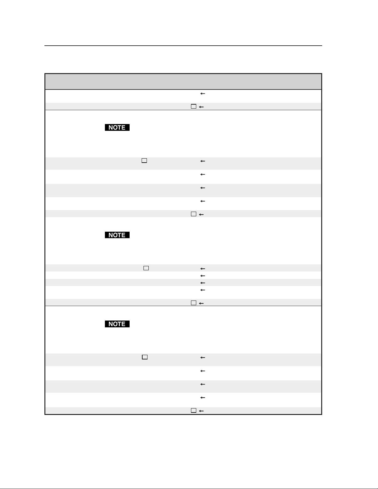
Programmer’s Guide, cont’d
Command/Response Table for RS-232 Commands (Cont’d)
Command ASCII Command Response Additional description
(host to scaler) (scaler to host)
Set blue gain value to default [BLU@] [OK] Reset the blue gain setting to its
factory default (128).
View the blue gain value [BLU?] [X8] Show the blue gain setting.
Color saturation
1. Color saturation adjustments are available only for NTSC interlaced
component video, S-video, and composite video inputs only.
2. No video adjustments are available for the input 4 video signal when it is
configured as passive (unscaled).
Set a specific color saturation value
Increment color saturation value [SAT+] [OK]
Decrement color saturation value [SAT-] [OK] Decrease the color saturation
Set color saturation value to default
View the color saturation value [SAT?] [X8] Show the color saturation setting.
[SAT X8] [OK] Specify the color saturation
adjustment.
Increase the color saturation
setting by one.
setting by one.
[SAT@] [OK] Reset the color saturation setting
to its factory default (128).
Hue
1. Hue adjustments are available only for NTSC interlaced component
video, S-video, and composite video inputs only.
2. No video adjustments are available for the input 4 video signal when it is
configured as passive (unscaled).
Set a specific hue value [HUE X8] [OK] Specify the hue adjustment.
Increment hue value [HUE+] [OK] Increase the hue setting by one.
Decrement hue value [HUE-] [OK] Decrease the hue setting by one.
Set hue value to default [HUE@] [OK] Reset the hue setting to its
factory default (128).
View the hue value [HUE?] [X8] Show the hue setting.
Sharpness
1. Sharpness adjustments are available only for interlaced component video,
S-video, and composite video inputs only.
2. No video adjustments are available for the input 4 video signal when it is
configured as passive (unscaled).
Set a specific sharpness value [SHP X9] [OK] Specify the sharpness
adjustment.
Increment sharpness value [SHP+] [OK] Increase the sharpness setting by
one.
Decrement sharpness value [SHP-] [OK] Decrease the sharpness setting
by one.
Set sharpness value to default [SHP@] [OK] Reset the sharpness setting to its
factory default (3).
View the sharpness value [SHP?] [X9] Show the sharpness setting.
IN1404XT Video Scaler and Switcher • Programmer’s Guide4-8
Page 65

Command/Response Table for RS-232 Commands (Cont’d)
Command ASCII Command Response Additional description
(host to scaler) (scaler to host)
Gamma
1. Gamma adjustments are available only for interlaced component video,
S-video, and composite video inputs only.
2. The gamma adjustment is not available for the input 4 video signal when
it is configured as passive (unscaled).
Set a specific gamma value [GAM
Increment gamma value [GAM+] [OK] Increase the gamma setting by
Decrement gamma value [GAM-] [OK] Decrease the gamma setting by
Set gamma value to default [GAM@] [OK] Reset the gamma setting to its
View the gamma value [GAM?] [
] [OK] Specify the gamma adjustment.
X10
one.
one.
factory default (10).
X10
] Show the gamma setting.
Noise filter
1. Noise filter adjustments are available only for interlaced component
video, S-video, and composite video inputs only.
2. The noise filter adjustment is not available for the input 4 video signal
when it is configured as passive (unscaled).
Set a specific noise filter value [NOISE
Increment noise filter value [NOISE+] [OK] Increase the noise filter setting by
Decrement noise filter value [NOISE-] [OK] Decrease the noise filter setting
Set noise filter value to default [NOISE@] [OK] Reset the noise filter setting to its
View the noise filter value [NOISE?] [
X11
] [OK] Specify the noise filter
adjustment.
one.
by one.
factory default (9).
X11
] Show the noise filter setting.
Comb/trap filter
The comb or trap filter setting is available only for composite video inputs
only on input 1 and input 2 only.
Select comb filter or trap filter [CTF
View the selected filter [CTF?] [
X12
] [OK] Select the comb filter, trap filter,
or neither.
] Show the filter selection.
X12
Horizontal tracking
The horizontal tracking adjustment is available for interlaced component
video, S-video, and composite video inputs only.
Set horizontal tracking [HTK
View horizontal tracking [HTK?] [
] [OK] Set horizontal tracking rate.
X13
X13
] View horizontal tracking rate.
Input labels
Set input label status [LBL
Set custom label [LBL=
Example: [LBL=DVD #1] [OK] Display the label “DVD #1”
X14
] [OK] Set the label feature (displayed
upon input selection) to
X15
] [OK] Set the label to the custom
contents
X15
.
when this input is selected, if
is on (1) or momentary (2).
X14
.
X14
4-9IN1404XT Video Scaler and Switcher • Programmer’s Guide
Page 66

Programmer’s Guide, cont’d
Command/Response Table for RS-232 Commands (Cont’d)
Command ASCII Command Response Additional description
(host to scaler) (scaler to host)
Input labels (continued)
View current label [LBL:] [
Example: [LBL] [DVD #1]
Reset custom label [LBL3] [OK] Erase custom label and return to
View the label status [LBL?] [
] Shows the current custom or
X15
default label for the selected
input.
default (Input n). Label status
) is not affected.
(
X14
X14
] Shows whether the label feature
is on, off, or momentary.
Horizontal size
Set a specific horizontal size value
Increase the horizontal size [SH+] [OK] Widen the picture by 1%.
Decrease the horizontal size [SH-] [OK] Narrow the picture by 1%.
Set horizontal size to default [SH@] [OK] Set the size to the default for the
View the horizontal size [SH?] [
[SH
] [OK] Set the size as a specific
X16
percentage.
selected resolution.
X16
]
Vertical size
Set a specific vertical size value
Increase the vertical size [SV+] [OK] Widen the picture by 1%.
Decrease the vertical size [SV-] [OK] Narrow the picture by 1%.
Set vertical size to default [SV@] [OK] Set the size to the default for the
View the vertical size [SV?] [
X16
[SV
] [OK] Set the size as a specific
percentage.
selected resolution.
] Show the vertical size setting.
X16
Horizontal shift
Set a specific horizontal shift value
Increase the horizontal shift [PH+] [OK] Shift the picture to the right.
Decrease the horizontal shift [PH-] [OK] Shift the picture to the left.
Set horizontal shift to default [PH@] [OK] Set the shift to the default for the
View the horizontal shift value [PH?] [
X17
[PH
] [OK] Shift the image on the screen a
specific amount.
selected resolution.
] Show the horizontal shift setting.
X17
Vertical shift
Set a specific vertical shift value
Increase the vertical shift [PV+] [OK] Move the picture up.
Decrease the vertical shift [PV-] [OK] Move the picture down.
Set vertical shift to default [PV@] [OK] Set the shift to the default for the
View the vertical shift value [PV?] [
X18
[PV
] [OK] Shift the image on the screen a
specific amount.
selected resolution.
X18
] Show the vertical size setting.
Pixel phase
Set a specific pixel sampling phase
Increment sampling value [PHS+] [OK] Increase the phase value.
Decrement sampling value [PHS-] [OK] Decrease the phase value.
Set pixel phase to default [PHS@] [OK] Set the pixel phase value to the
[PHS
X19
] [OK] Specify the pixel sampling phase.
default for the selected
resolution.
IN1404XT Video Scaler and Switcher • Programmer’s Guide4-10
Page 67

Command/Response Table for RS-232 Commands (Cont’d)
Command ASCII Command Response Additional description
(host to scaler) (scaler to host)
Pixel phase (continued)
View the sampling value [PHS?] [
X19
] Show the pixel sampling phase.
Freeze
Video freeze on [FRZ1] [OK] Freeze the video output.
Video freeze off [FRZ0] [OK] Unfreeze.
Toggle video freeze [FRZ] [OK]
Change the state of video freeze
(off to on or on to off).
View freeze [FRZ?] [
X2
] View the status of the freeze
setting.
Memory preset
Save preset [MSAV
Recall preset [MRCL
Reset preset [MRST
] [OK] Save the video, balance, and
X20
input settings as preset
X20
] [OK] Recall preset
X20
] [OK] Erase preset
X20
X20
settings.
settings.
X20
.
Volume
Set volume [VOL
Increment level [VOL+] [OK] Increase balance level for the
Decrement level [VOL-] [OK] Decrease volume level for the
Set volume level to default [VOL@] [OK] Set the volume to the default.
View volume level [VOL?] [
] [OK] Set volume for the selected input.
X21
selected input.
selected input.
] View the volume level for the
X21
selected input.
Bass
Set bass [BAS
Increment level [BAS+] [OK] Increase bass level for the
Decrement level [BAS-] [OK] Decrease bass level for the
Set bass level to default [BAS@] [OK] Set the input bass to the default.
View bass level [BAS?] [
X22
] [OK] Set bass for the selected input.
selected input.
selected input.
] View the bass level for the
X22
selected input.
Treble
Set treble [TRE
Increment level [TRE+] [OK] Increase treble level for the
Decrement level [TRE-] [OK] Decrease treble level for the
Set treble level to default [TRE@] [OK] Set the input treble to the default.
View treble level [TRE?] [
] [OK] Set treble for the selected input.
X23
selected input.
selected input.
X23
] View the treble level for the
selected input.
Balance
Set balance [BAL
Increase balance right [BALR] [OK] Move balance right for the
Increase balance left [BALL] [OK] Move balance left for the selected
Set balance level to default (center)
[BAL@] [OK] Set the input balance to the
] [OK] Set balance for the selected input.
X24
selected input.
input.
center.
4-11IN1404XT Video Scaler and Switcher • Programmer’s Guide
Page 68

Programmer’s Guide, cont’d
Command/Response Table for RS-232 Commands (Cont’d)
Command ASCII Command Response Additional description
(host to scaler) (scaler to host)
Balance (continued)
View balance level [BAL?] [
] View the balance level for the
X24
selected input.
Audio mute
Audio mute on [MUTE1] [OK] Mute the audio output.
Audio mute off [MUTE0] [OK] Unmute.
Toggle audio mute [MUTE] [OK] Change the state of audio mute
(off to on or on to off).
View mute [MUTE?] [X2] View the status of the mute
setting.
Disable front panel
Enable front panel [FP0] [OK] Unlock the front panel.
Disable front panel [FP1] [OK] Lock the front panel.
Toggle front panel mode [FP] [OK] Change the state of front panel
(enabled to disabled or disabled
to enabled).
View front panel mode [FP?] [X2] View the status of front panel
(enabled or disabled).
Information requests
Query firmware version number [INFO?] [
] Show the scaler firmware
X25
version.
Resets
Partial reset to factory defaults [RES
Example: [RES4] [OK] Reset all output settings.
Complete reset to factory defaults [RES000] [Please Wait] Reset all video, balance, input,
X26
] [OK] Reset all
defaults.
output, and RS-232 settings to
the factory default.
X26
settings to factory
RS-232 settings
The scaler and the computer, PDA, or control system must communicate at
the same baud rate. If you change the scaler’s baud rate, you will lose
communications between the computer, PDA, or control system and the
scaler until you set the controller to match the scaler’s baud rate.
Set baud rate [ACI
View baud rate [ACI?] [
X27
] [OK] Set the communications rate to
The scaler and the computer, PDA, or control system must use the same
deliminators to communicate. If you change the scaler’s baud deliminators,
you will lose communications between the computer, PDA, or control system
and the scaler until you set the controller to match the scaler’s deliminators.
Set delimitors [CMDCD
View delimitors [CMDCD?] [
X28
] [OK] Set the leading and end codes to
IN1404XT Video Scaler and Switcher • Programmer’s Guide4-12
.
X27
] Read the scaler’s baud rate.
X27
X28
.
] Read the scaler’s leading and
X28
end codes.
Page 69

Command/Response Table for RS-232 Commands (Cont’d)
Command ASCII Command Response Additional description
(host to scaler) (scaler to host)
Front panel buttons
Menu button [MENU] [OK] The same as pushing the front
panel Menu button. The on-
screen display shows the menu
system.
Left button [LEFT] [OK] The same as pushing the front
panel button.
Up button [UP] [OK] The same as pushing the front
panel (Menu , not volume ).
Down button [DOWN] [OK] The same as pushing the front
panel (Menu , not volume ).
Right button [RIGHT] [OK] The same as pushing the front
panel button.
Enter button [ENTER] [OK] The same as pushing the front
panel Enter button. Any
highlighted or changed on-
screen display parameters are
saved.
The rest of the RS-232 commands are a complex set of adjustments to optimize
the scaler for non-standard video inputs. Most users will not encounter such
signals. Extron recommends that only knowledgeable and qualified video
technicians make changes to these settings.
Active area
The active pixels and total pixels adjustments are interactive. Setting one of
these variables may require adjusting the other.
Set a specific active pixel value [AP
Increment active pixels value [AP+] [OK] Increase the active pixels setting
Decrement active pixels value [AP-] [OK] Decrease the active pixels setting
Set active pixels value to default [AP@] [OK] Reset the active pixels setting to
View the active pixels value [AP?] [
Set a specific active line value [BV
Increment active lines value [BV+] [OK] Increase the active lines setting
Decrement active lines value [BV-] [OK] Decrease the active lines setting
Set active lines value to default [BV@] [OK] Reset the active lines setting to
View the active lines value [BV?] [
X29
] [OK] Specify the active pixels
adjustment.
by one.
by one.
its factory default (9).
] Show the active pixels setting.
X29
X30
] [OK] Specify the active lines
adjustment.
by one.
by one.
its factory default (9).
] Show the active lines setting.
X30
Blanking
Set a specific H blanking value [BH
Increment H blanking value [BH+] [OK] Increase the horizontal blanking
Decrement H blanking value [BH-] [OK] Decrease the horizontal blanking
] [OK] Specify the active pixels
X31
adjustment.
setting by one.
setting by one.
4-13IN1404XT Video Scaler and Switcher • Programmer’s Guide
Page 70

Programmer’s Guide, cont’d
Command/Response Table for RS-232 Commands (Cont’d)
Command ASCII Command Response Additional description
(host to scaler) (scaler to host)
Blanking (continued)
Set H blanking value to default [BH@] [OK] Reset the horizontal blanking
setting to its factory default (9).
View the H blanking value [BH?] [
Set a specific V blanking value [BV
Increment V blanking value [BV+] [OK] Increase the vertical blanking
Decrement V blanking value [BV-] [OK] Decrease the vertical blanking
Set V blanking value to default [BV@] [OK] Reset the vertical blanking
View the V blanking value [BV?] [
] [OK] Specify the vertical blanking
X32
X31
] Show the horizontal blanking
setting.
adjustment.
setting by one.
setting by one.
setting to its factory default (9).
X32
] Show the vertical blanking
setting.
Total pixels
The total pixels and active pixels adjustments are interactive. Setting one of
these variables may require adjusting the other.
Set a specific total pixel value [TP
Increment total pixels value [TP+] [OK] Increase the total pixels setting
Decrement total pixels value [TP-] [OK] Decrease the total pixels setting
Set total pixels value to default [TP@] [OK] Reset the total pixels setting to its
View the total pixels value [TP?] [
] [OK] Specify the total pixels
X33
adjustment.
by one.
by one.
factory default (9).
X33
] Show the total pixels setting.
Scan type
1. The scan type settings are available for RGBHV, RGBS, RGsB, and
progressive component video inputs only.
2. Three scan type options are available; one, two, or all three can be turned
on simultaneously.
Toggle interlaced on or off [ST 0] [OK] Toggle the interlaced function on
or off.
Toggle swapped fields on or off [ST 1] [OK] Toggle the swapped fields
function on or off.
Toggle invert sync on or off [ST 2] [OK] Toggle the inverted sync function
on or off.
View scan type value [ST?] [
] View scan type settings.
X34
Input mode
The input mode settings are available for RGBHV, RGBS, RGsB, and
progressive component video inputs only.
Set input mode to autodetect [ST 0] [OK]
Set input mode to lockout changes
[ST 1] [OK] Prevents the scaler from
Allows the scaler to automatically
detect new input sampling rates
and adjust itself accordingly.
switching back and forth
between input sampling rates.
IN1404XT Video Scaler and Switcher • Programmer’s Guide4-14
Page 71

Command/Response Table for RS-232 Commands (Cont’d)
Command ASCII Command Response Additional description
(host to scaler) (scaler to host)
Input mode (continued)
Set input mode to user defined [ST 2] [OK] All input sampling rates have the
same user-definable settings.
However, the inputs are
restricted to values that are close
to the sampling rate detected. If
a full range of values is
necessary, the user-defined mode
can be manually selected.
Input mode (continued)
If the auto-detect mode cannot determine the input sampling rate, the userdefined mode is selected automatically.
Redetect the input mode [ST 3] {none} Allows users to initiate a new
detection sequence and reload
the input/output settings
View scan type value [ST?] [
] View scan type settings.
X35
4-15IN1404XT Video Scaler and Switcher • Programmer’s Guide
Page 72

Programmer’s Guide, cont’d
IN1404XT Video Scaler and Switcher • Programmer’s Guide4-16
Page 73

IN1404XT Video Scaler and Switcher
Appendix A
A
Reference Information
Specifications
Part Numbers
Page 74

Reference Information
Specifications
Video input
Number/signal type ................... 2 RGBHV, RGBS, RGsB, RGBcvS, component video
4 S-video, composite video
Connectors ................................... 2 x 5 female BNC (inputs 3 and 4, all video formats)
(2) 4-pin mini DIN (inputs 1 and 2, S-video)
2 female BNC (inputs 1 and 2, composite)
Nominal level ............................... 1V p-p for Y of component video and S-video, and for composite video
0.7V p-p for RGB
0.3V p-p for R-Y and B-Y of component video, and for C of S-video
Minimum/maximum levels....... 0V to 1.0V p-p with no offset
Impedance .................................... 75 ohms
Horizontal frequency .................. Autoscan 15 kHz to 60 kHz (RGB)
Vertical frequency ....................... Autoscan 50 Hz to 120 Hz
Resolution range.......................... Autoscan 720 x 525 to 1600 x 1200
Video processing
Decoder ......................................... 8 bit digital
Digital sampling ...........................
Colors ............................................ 16.78 million
PRELIMINARY
24 bit, 8 bits per color
Video output
Number/signal type ................... 2 RGBHV, RGBS, RGsB, scaled RGB
1 set of proprietary analog signals
Connectors ................................... 5 BNC female
(1) 15-pin HD female
1 RJ-45 female
Nominal level ............................... 0.7V p-p
Minimum/maximum levels....... 0V to 0.7V p-p
Impedance .................................... 75 ohms
Scaled resolution .......................... 640x480
1152x864
1365x1024
1
= at 56 Hz 2 = at 60 Hz 3 = at 65 Hz 4 = at 72 Hz 5 = at 75 Hz
6
= at 85 Hz 7 = at 96 Hz 8 = at 100 Hz 9 = 120 Hz
Switching type.............................. Seamless or RGB delayed switching
2,4,5,6,7,8,9
2,4,5,6,
2
, 800x600
, 1280x720
2,4,5,6,7,8,9
2,4,5,6,7,8
, 1280x768
Sync
Input type ..................................... RGBHV, RGBS, RGsB
Output type .................................. RGBHV, RGBS, RGsB
Standards ...................................... NTSC 3.58, NTSC 4.43, PAL, SECAM
Input level ..................................... 0V to 5.0V p-p
Output level .................................. 0V to 5.0V p-p
Input impedance .......................... 1 kohms
Output impedance ....................... 75 ohms
Max input voltage ........................ 5.0V p-p
Polarity .......................................... Positive or negative (selectable)
, 852x480
2,4,5,6,7,8,9
1,2,3
, 1280x1024
, 1024x768
2,4,5,
2,4,5,6,7,8
,
, 1365x768
2,4,5
,
IN1404XT Video Scaler and Switcher • Reference InformationA-2
Page 75

Audio
Gain ................................................ Unbalanced output: 0dB
???Frequency response ............... 20 Hz to 20 kHz, ±0.05dB
???THD + Noise........................... 0.03% @ 1 kHz at nominal level, 0dB gain
???S/N ............................................ >90dB at rated maximum output
???Crosstalk .................................. <-80dB @ 1 kHz, fully loaded
???Stereo channel separation .... >90dB @ 1 kHz
???CMRR ...................................... >75dB @ 20 Hz to 20 kHz
Audio input
Number/signal type ................... 4 stereo, unbalanced
Connectors ................................... 4x2 (left and right) RCA connectors
Impedance .................................... >10 kohms unbalanced/balanced, DC coupled
Nominal level .............................. +4dBu (1.23V), -10dBV (316mV)
PRELIMINARY
Audio output
Number/signal type ................... 1 stereo, unbalanced
Connectors ................................... 1x2 (left and right) RCA connectors
???Impedance ............................... 50 ohms unbalanced, 100 ohms balanced
???Gain error ................................ ±0.1dB channel to channel
???Maximum level (Hi-Z) .......... >+21dBu, balanced or unbalanced at stated %THD+N
???Maximum level (600 ohm) ... >+15dBm, balanced or unbalanced at stated %THD+N
0dBu = 0.775 volts (RMS).
Control/remote — switcher
Serial control port ........................ RS-232, 3-pole captive screw connector
Baud rate and protocol ............... 1200 to 57,600, 8-bit, 1 stop bit, no parity
Serial control pin configurations 1 = TX, 2 = GND, 3 = RX
General
Power ............................................ 90VAC to 260VAC, 50/60 Hz, 60 watts, internal, auto-switchable
Temperature/humidity .............. Storage -40° to +158°F (-40° to +70°C) / 10% to 90%, non-condensing
Operating +32° to +122°F (0° to +50°C) / 10% to 90%, non-condensing
Rack mount .................................. Yes, with included rack mount kit IN9123B
Enclosure type .............................. Metal
Enclosure dimensions ................. 1.75" H x 17.0" W x 12.2" D (1U high, full rack width)
4.5 cm H x 43.2 cm W x 31.0 cm D
(Depth excludes connectors.)
Product weight............................. 3.5 lbs (1.6 kg)
Shipping weight ........................... 7 lbs (3.5 kg)
Vibration ....................................... ISTA/NSTA 1A in carton (International Safe Transit Association)
Listings .......................................... ETL (UL1950)
Compliances ................................. CE
MTBF ............................................. 30,000 hours
Warranty....................................... 3 years parts and labor
Specifications are subject to change without notice.
A-3IN1404XT Video Scaler and Switcher • Reference Information
Page 76

Reference Information, cont’d
Part Numbers
Included parts
These items are included in each order for an IN1404XT:
Included parts Part number
IN1404XT Video Scaler and Switcher 60-732-01
Rack mount ears for IN1403/1404//IN3600 Switchers (black) 70-391-01
Rubber feet (4)
IEC power cord
Tweeker (small screwdriver)
IN1404XT User’s Manual
Optional accessoriess
Part Part number
RCA-to-BNC adapter 10-264-01
SVHS - BNC adapter 26-353-01
Wall mount twisted pair RGBHV receiver - black VTR001CM-1
Wall mount twisted pair RGBHV receiver - white VTR001CM-2
Table top twisted pair RGBHV receiver - black VTR001CM-3
TP R BNC A twisted pair RGBHV video and audio receiver 60-351-02
TP R 15HD A twisted pair RGBHV video and audio receiver 60-450-01
TP R BNC AV twisted pair RGB video, composite video and audio
receiver (RGB receiver portion used only) 60-350-02
Cables
VGA cable
When using signals with a scanning frequency of 15-125 kHz and running
distances of 100 feet or more, use high resolution BNC cables to achieve
maximum performance.
Male-to-female VGA Cable Part number
VGA 3’ MHR (molded) (0.9 m) 26-112-17
VGA 6’ MHR (molded) (1.8 m) 26-122-15
VGA 15’ MHR (molded) (4.6 m) 26-112-01
VGA 25’ MHR (molded) (7.6 m) 26-112-05
VGA 35’ MHR (10.7 m) 26-112-27
VGA 50’ MHR (15.25 m) 26-112-02
VGA 75’ MHR (22.9 m) 26-112-03
VGA 100’ MHR (30.5 m) 26-112-04
VGA 150’ MHR (45.7 m) 26-112-09
VGA 200’ MHR (61.0 m) 26-112-08
VGA 250’ MHR (76.2 m) 26-112-16
IN1404XT Video Scaler and Switcher • Reference InformationA-4
Page 77

Male-to-male VGA Cable
VGA M3’ MHR (molded) (0.9 m) 26-238-14
VGA M6’ MHR (molded) (1.8 m) 26-122-01
VGA M10’ MHR (molded) (4.6 m) 26-238-07
VGA M15’ MHR (molded) (4.6 m) 26-238-02
VGA M25’ MHR (molded) (7.6 m) 26-238-03
VGA M35’ MHR (10.7 m) 26-238-16
VGA M50’ MHR (15.25 m) 26-238-04
VGA M75’ MHR (22.9 m) 26-238-05
VGA M100’ MHR (30.5 m) 26-238-06
VGA M150’ MHR (45.7 m) 26-238-09
VGA M200’ MHR (61.0 m) 26-238-08
VGA M250’ MHR (76.2 m) 26-238-15
Pre-cut cables
BNC-4 Mini HR cable is used for RGBS cable runs, and BNC-5 Mini HR cable is
used for RGBHV cable runs. Either type can also be used for composite video,
S-video, or RGsB. All Extron BNC cables have male connectors on both ends. A
plenum version of the BNC-5 Mini HR cable is also available.
BNC-4 Mini HR Cable Part number
BNC-4-25’ MHR (25 feet/7.5 meters) 26-210-04
BNC-4-50’ MHR (50 feet/15.0 meters) 26-210-05
BNC-4-75’ MHR (75 feet/23.0 meters) 26-210-06
BNC-4-100’ MHR (100 feet/30.0 meters) 26-210-07
BNC-4-150’ MHR (150 feet/45.0 meters) 26-210-08
BNC-4-200’ MHR (200 feet/60.0 meters) 26-210-09
BNC-4-250’ MHR (250 feet/75.0 meters) 26-210-54
BNC-4-300’ MHR (300 feet/90.0 meters) 26-210-53
BNC-5 Mini HR Cable
BNC-5-25’ MHR (25 feet/7.5 meters) 26-260-03
BNC-5-50’ MHR (50 feet/15.0 meters) 26-260-04
BNC-5-75’ MHR (75 feet/23.0 meters) 26-260-16
BNC-5-100’ MHR (100 feet/30.0 meters) 26-260-05
BNC-5-150’ MHR (150 feet/45.0 meters) 26-260-12
BNC-5-200’ MHR (200 feet/60.0 meters) 26-260-06
BNC-5-250’ MHR (250 feet/75.0 meters) 26-260-18
BNC-5-300’ MHR (300 feet/90.0 meters) 26-260-14
A-5IN1404XT Video Scaler and Switcher • Reference Information
Page 78

Reference Information, cont’d
Skew-free A/V cable Part number
Skew-Free A/V UTP cables are not recommended for Ethernet/LAN applications.
3’ Skew-free A/V UTP 26-569-01
6’ Skew-free A/V UTP 26-569-02
12’ Skew-free A/V UTP 26-569-03
25’ Skew-free A/V UTP 26-569-04
35’ Skew-free A/V UTP 26-569-05
50’ Skew-free A/V UTP 26-569-06
75’ Skew-free A/V UTP 26-569-07
100’ Skew-free A/V UTP 26-569-08
150’ Skew-free A/V UTP 26-569-09
200’ Skew-free A/V UTP 26-569-10
250’ Skew-free A/V UTP 26-569-11
300’ Skew-free A/V UTP 26-569-12
25’ Skew-free Plenum 26-570-04
35’ Skew-free Plenum 26-570-05
50’ Skew-free Plenum 26-570-06
75’ Skew-free Plenum 26-570-07
100’ Skew-free Plenum 26-570-08
150’ Skew-free Plenum 26-570-09
200’ Skew-free Plenum 26-570-10
250’ Skew-free Plenum 26-570-11
300’ Skew-free Plenum 26-570-12
Bulk cable
Super High Resolution Cable Part number
SHR-1 bulk , 500’ 22-098-02
SHR-1 bulk , 1000’ 22-098-03
SHR-4 bulk , 500’ 22-099-02
SHR-5 bulk , 500’ 22-100-02
BNC-4 Mini HR Cable Part number
BNC-4 Mini HR bulk, 500’ 22-032-02
BNC-4 Mini HR bulk, 1000’ 22-032-03
BNC-5 Mini HR Cable Part number
BNC-5 Mini HR bulk, 500’ 22-020-02
BNC-5 Mini HR bulk, 1000’ 22-020-03
IN1404XT Video Scaler and Switcher • Reference InformationA-6
Page 79

Plenum BNC-5 Mini HR Cable Part number
Plenum BNC-5 Mini HR bulk, 500’ 22-103-02
Plenum BNC-5 Mini HR bulk, 1000’ 22-103-03
Bulk cable in lengths up to 5000' (1524 meter) rolls is available with or
without connectors.
Skew-free A/V cable Part number
Skew-free A/V UTP 1000’ (Bulk) (non-plenum) 22-141-03
Skew-free A/V UTP 1000’ (Bulk) (plenum) 22-142-03
Assorted connectors, cables, and adapters
Connectors Part number
BNC Mini HR crimp connectors, qty. 50 100-074-51
SHR male crimp connectors, qty. 50 100-075-51
BNC bulkhead connectors, qty. 50 (for custom wall plates) 100-076-51
CAT 6 jack (black) 10-463-10
Assorted cables and adapters Part number
SVHS 6’ (6 feet/1.8 meters) 26-316-02
SVHSM - BNCM-3’ 26-353-03
A-7IN1404XT Video Scaler and Switcher • Reference Information
Page 80

Reference Information, cont’d
IN1404XT Video Scaler and Switcher • Reference InformationA-8
Page 81

Extron’s Warranty
Extron Electronics warrants this product against defects in materials and workmanship for a period
of two years from the date of purchase. In the event of malfunction during the warranty period
attributable directly to faulty workmanship and/or materials, Extron Electronics will, at its option,
repair or replace said products or components, to whatever extent it shall deem necessary to restore
said product to proper operating condition, provided that it is returned within the warranty period,
with proof of purchase and description of malfunction to:
USA, Canada, South America, Europe, Africa, and the Middle East:
and Central America:
Extron Electronics, Europe
Extron Electronics Beeldschermweg 6C
1230 South Lewis Street 3821 AH Amersfoort
Anaheim, CA 92805, USA The Netherlands
Asia: Japan:
Extron Electronics, Japan
Extron Electronics, Asia Kyodo Building
135 Joo Seng Road, #04-01 16 Ichibancho
PM Industrial Bldg. Chiyoda-ku, Tokyo 102-0082
Singapore 368363 Japan
This Limited Warranty does not apply if the fault has been caused by misuse, improper handling
care, electrical or mechanical abuse, abnormal operating conditions or non-Extron authorized
modification to the product.
If it has been determined that the product is defective, please call Extron and ask for an Applications
Engineer at (714) 491-1500 (USA), 31.33.453.4040 (Europe), 65.6383.4400 (Asia), or 81.3.3511.7655 (Japan)
to receive an RA# (Return Authorization number). This will begin the repair process as quickly as
possible.
Units must be returned insured, with shipping charges prepaid. If not insured, you assume the risk
of loss or damage during shipment. Returned units must include the serial number and a
description of the problem, as well as the name of the person to contact in case there are any
questions.
Extron Electronics makes no further warranties either expressed or implied with respect to the
product and its quality, performance, merchantability, or fitness for any particular use. In no event
will Extron Electronics be liable for direct, indirect, or consequential damages resulting from any
defect in this product even if Extron Electronics has been advised of such damage.
Please note that laws vary from state to state and country to country, and that some provisions of
this warranty may not apply to you.
Page 82

www.extron.com
Extron Electronics, USA
1230 South Lewis Street
Anaheim, CA 92805
USA
714.491.1500
Fax 714.491.1517
Extron Electronics, Europe
Beeldschermweg 6C
3821 AH Amersfoort
The Netherlands
+31.33.453.4040
Fax +31.33.453.4050
Extron Electronics, Asia
135 Joo Seng Road, #04-01
PM Industrial Building
Singapore 368363
+65.6383.4400
Fax +65.6383.4664
© 2005 Extron Electronics. All rights reserved.
Extron Electronics, Japan
Kyodo Building
16 Ichibancho
Chiyoda-ku, Tokyo 102-0082 Japan
+81.3.3511.7655
Fax +81.3.3511.7656
 Loading...