

Page 1

User’s Guide
HDSDI-ACR 100
SDI-AVR 100
High Definition SDI to Component Video/RGB Converter
SDI to Video/RGB Converter
68-553-01 C
Printed in the USA
02 02
Page 2
Installation
Overview
The Extron HDSDI-ACR 100 converts a high definition (HD) serial
digital interface (SDI) input (SMPTE-292M) to either analog component
or RGB video. The converter supports the 720p, 1080i, and 1080p HDTV
rates. The 1080p rate is limited to a maximum 30 Hz refresh rate and
includes 1080p segmented frame 23.94/24. DIP switches select between
RGB and component video, and, for component video output, between
bi-level and tri-level sync, and sync on the Y output or on all outputs.
The Extron SDI-AVR 100 converts an SDI (4:2:2) video input at the
270 Mbs rate to analog video. When an SDI input is applied, the
converter produces simultaneous composite and S-video outputs, and
either component (Y, R-Y, and B-Y) or RGB video. A DIP switch selects
between a component or RGB video output. The SDI-AVR 100 accepts
NTSC, PAL, and Betacam (Beta 50/60), autodetects the format, and
deserializes the input. The converter can output NTSC or PAL color
bars, which are DIP switch selectable.
HDTV Tape Deck
HDTV Camera
Figure 1 — Typical HDSDI-ACR 100 and SDI-AVR 100
applications
The input signal is equalized for distances of 330 feet (100 meters)
(HDSDI-ACR 100) or 1000 feet (305 meters) (SDI-AVR 100) on high
quality cable such as Extron SHR cable. A reclocked loop-through
allows the HDSDI/SDI input to be sent to other equipment.
The user must select between an RGB or component video output using
a DIP switch. The converters output separate H and V sync signals and
composite sync simultaneously. Selecting the sync-on-green output
requires changing a DIP switch position.
The converters have internal switching power supplies.
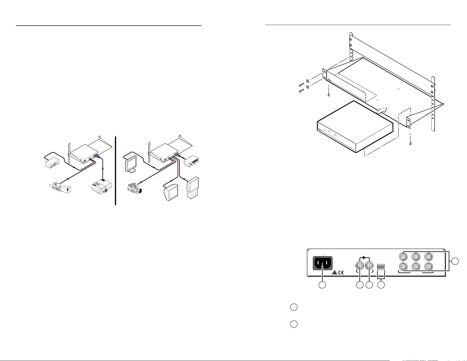
Installation
1. For optional rack mounting, mount the converter on one side of a
19" 1U Universal Rack Shelf (Extron part #60-190-01) (figure 2).
a. If feet were previously installed on the bottom of the case,
HDSDI-ACR 100
SPARE
BI/TRI-LEVEL
RGB/COMPONENT
SOG OFF/ON
T
U
O
IN
T
U
P
N
I
I
A
D
1
.
S
0
D
H
V
0
4
2
0
0
1
remove them.
Y
B
/
B
Y
/
G
S
Y
R
/
R
V
H
S
T
U
P
T
U
O
Projector
Monitor
Camera
SDI-AVR 100
A
2
.
0
z
H
0
6
/
0
5
V
0
4
2
0
0
1
Monitor
Y
R
/
R
H
O
E
D
I
V
T
U
S
P
T
U
O
E
T
I
S
O
P
S
T
M
T
U
O
U
P
C
T
P
U
T
O
U
O
IN
NTSC/PAL
COLOR BARS
BETA
SET UP
RGB/YUV
SOG
T
U
N
O
O
F
F
O
T
U
P
IN
I
D
S
Y
B
/
B
Y
/
G
S
V
Betacam Recorder
Large Screen
Rear Projector
False front panel
uses 2 front holes.
720
FORMAT
P
1080
I
1080
P
H
H
D
S
D
D
S
I
T
O
D
V
I
I
-
D
A
E
O
C
/
R
R
G
B
1
C
0
O
N
0
V
E
R
T
E
R
Use 2 mounting holes on
opposite corners.
(2) 4-40 x 1/8" Screws
Figure 2 — Rack mounting the SDI-AVR 100
b. Mount the SDI-AVR 100 on the rack shelf, using two 4-40 x
1/8 screws in opposite (diagonal) corners.
2. If desired, attach a false front panel or a second ½-rack-width
device to the other side of the shelf.
3. Attach the rack shelf to the rack using four 10-32 x ¾” bolts and
four #10 beveled dress washers.
Rear Panel Cabling
Figure 3 shows the HDSDI-ACR 100 connections and DIP switches.
Figure 4 shows the SDI-AVR 100.
100-240V 0.1A
IN
OUT
SOG OFF/ON
RGB/COMPONENT
BI/TRI-LEVEL
SPARE
50/60 Hz
HDSDI INPUT
216 7
Figure 3 — HDSDI-ACR 100 rear panel
Input In connector — Connect an HDSDI (HDSDI-ACR 100) or
1
SDI (SDI-AVR 100) input to this BNC connector.
Input Out connector — Connect an HDSDI (HDSDI-ACR 100) or
2
SDI (SDI-AVR 100) device to this BNC connector. The converter
outputs a reclocked SDI or HDSDI loop-though on this BNC.
R/R-Y G/Y B/B-Y
HVS
OUTPUTS
5
2
HDSDI-ACR 100 and SDI-AVR 100 • Installation 3HDSDI-ACR 100 and SDI-AVR 100 • Installation
Page 3

Output video format SOG
RGB/
Component
Bi/tri-level
RGBHV/RGBS Off Off Either
RGsB On Off Either
Y, R-Y, B-Y w/ bi-level on Y Either On Off
Y, R-Y, B-Y w/ tri-level on Y Either On On
Output video format SOG RGB/YUV
RGBHV/RGBS Off Off
RGsB On
Either
Off
Y, R-Y, B-Y On
Installation
R/R-Y G/Y B/B-Y
HVS
100-240V 50/60 Hz 0.2A
IN
OUT
SDI INPUT OUTPUTS
COMPOSITE
S-VIDEO
OUTPUT
NTSC/PAL
OUTPUT
SOG
RGB/YUV
SET UP
BETA
COLOR BARS
ON
OFF
21 36 47
Figure 4 — SDI-AVR 100 rear panel
Composite Output connector (SDI-AVR 100 only) — Connect a
3
composite video display device to this BNC connector. This
output is available whenever an active SDI signal is applied to the
SDI input connector, 1.
S-video Output connector (SDI-AVR 100 only) — Connect an
4
S-video device to this 4-pin mini DIN connector. This output is
available whenever an active SDI signal is applied to the SDI
input connector, 1.
RGB/component video output connectors
5
Ensure that the rear panel DIP switches are in the correct
configuration (see Rear Panel Controls).
RGBHV
Video
R/R-Y G/Y B/B-Y
HVS
RGBHV video connection —
Connect to five BNC connectors
as shown.
RGBS video connection —
Connect to four BNC connectors
as shown.
RGsB and component video
connection — Connect to three
RGBS
Video
R/R-Y G/Y B/B-Y
HVS
BNC connectors as shown.
AC power connector — Plug a
6
standard IEC power cord into
this connector to connect the
converter to a 100 to 240VAC, 50
Hz or 60 Hz power source.
RGsB or
Component
Video
R/R-Y
HVS
G/Y B/B-Y
RGB/Component (HDSDI-ACR 100) or RGB/YUV (SDI-
5
SOG
ON
OFF
AVR 100) switch — Set this switch to the Off position to
RGB/YUV
SET UP
BETA
COLOR BARS
NTSC/PAL
output RGB video. Set the switch on for component video.
Bi/tri-level switch (HDSDI-ACR 100 only) — Set this
switch to the On position to output tri-level sync on the
SOG OFF/ON
ON
OFF
component video output. Set the switch off for bi-level
RGB/COMPONENT
BI/TRI-LEVEL
SPARE
sync.
HDSDI-ACR 100 switch configuration
SDI-AVR 100 switch configuration
Set Up switch (SDI-AVR 100 only) — Set this switch to the On position
to output an NTSC signal that is on the 7.5 IRE pedestal. Set the
switch off to return the signal to the normal level.
Beta switch (SDI-AVR 100 only) — Set this switch to the On position to
set the color level of the YUV output to the Betacam level. Set the
switch off to restore the YUV output to the normal level. If a
Betacam signal is input, the switch should be set to On to output
the Betacam format. Otherwise, the output will be NTSC or PAL.
Color Bars switch (SDI-AVR 100 only) — Set this switch to the On
position to output NTSC or PAL color bars. Set the switch off for
the converted video input.
NTSC/PAL switch (SDI-AVR 100 only) — Used in conjunction with
the Color Bars switch only, set this switch to the On position to
output PAL color bars. Set the switch off for NTSC color bars.
Rear Panel Controls
DIP switches
7
SOG switch — Set this switch to the On position to output sync-
4
on-green for RGB video (RGsB). Set the switch off for
RGBHV or RGBS video.
Front Panel Indicators
All indicators are on the front panel. Figure 5 and figure 6 show
HDSDI-ACR 100 and SDI-AVR 100 indicators.
Power LED — The Power LED indicates that power is on.
1
720P LED (HDSDI-ACR 100 only) — The 720P LED indicates that
2
the converter is outputting the HDTV 720P video format.
HDSDI-ACR 100 and SDI-AVR 100 • Installation and Operation 5HDSDI-ACR 100 and SDI-AVR 100 • Installation
Page 4

Indicators and Specifications
FORMAT
720P1080I1080
1 2 3 4
Figure 5 — HDSDI-ACR 100 front panel
LOCK
1 5
Figure 6 — SDI-AVR 100 front panel
1080I LED (HDSDI-ACR 100 only) — The 1080I LED indicates
3
that the converter is outputting the HDTV 1080I video format.
1080P LED (HDSDI-ACR 100 only) — The 1080P LED indicates
4
that the converter is outputting the HDTV 1080P video format.
Lock LED (SDI-AVR 100 only) — The Lock LED indicates that
5
the converter is locked to the 270 Mbs input signal.
P
HDSDI-ACR 100
HDSDI TO VIDEO/RGB CONVERTER
SDI-AVR 100
SDI TO VIDEO/RGB CONVERTER
The equalization applied to the SDI-AVR 100’s input signal is
sufficient for an input coaxial cable length of at least 1000 feet (305
meters) of Extron SHR cable or Belden 8281 cable.
The equalization applied to the HDSDI-ACR 100’s input signal is
sufficient for an input coaxial cable length of at least 330 feet (100
meters) of Extron SHR cable or Belden 8281 cable.
Minimum/maximum levels ...... 0.5V to 1.0V p-p with no offset
Impedance .................................... 75 ohms
Return loss .................................... >-15dB @ 0 MHz to 270 MHz
Maximum DC offset .................... ±0.5V
Video processing
Encoder ......................................... 10 bit digital
Frequency response ..................... Luminance ................ 0 to 5.75 MHz, ±0.5dB
Chroma .................... 0 to 2.75 MHz, ±0.5dB
S/N ................................................ >70dB
RGB matrix error ......................... <1%
Video signal characteristics — for color bar output on the
SDI-AVR 100 only
Dot clock ....................................... 27 MHz
Pixel clock accuracy ..................... 30 ppm
Specifications
Video
Differential phase error .............. SDI-AVR 100 ............ <1º
Differential gain error ................. SDI-AVR 100 ............ <1%
Video input and loop-through
Number/signal type
SDI-AVR 100 .................... 1 SDI (4:2:2, SMPTE 259M-C)
HDSDI-ACR 100 .............. 1 HDSDI (SMPTE 292M)
Connectors
SDI-AVR 100 .................... 1 female BNC (SDI input)
1 female BNC (SDI reclocked loop-through)
HDSDI-ACR 100 .............. 1 female BNC (HDSDI input)
1 female BNC (HDSDI reclocked loop-through)
6
Video output
Number/signal type
SDI-AVR 100 .................... 1 composite video and 1 S-video, and
1 analog RGBHV/RGBS/RGsB or component
video (Y, R-Y, B-Y) (switch selectable)
HDSDI-ACR 100 .............. 1 analog RGBHV/RGBS/RGsB or component
video (Y, R-Y, B-Y) (switch selectable)
Connectors
SDI-AVR 100 .................... 1 female BNC (composite video)
1 female 4-pin mini DIN (S-video)
6 female BNC (RGB, component video, or S-video)
HDSDI-ACR 100 .............. 6 female BNC
Levels ............................................. Composite video ...... 1V p-p (nominal)
S-video .................... 1V p-p/luma, 0.3V p-p/
chroma (nominal)
RGB .................... 0.7V (nominal)
Component video .... Y = 1V p-p; R-Y, B-Y = 1V
p-p (nominal)
Levels depend on the format selected (NTSC, PAL, Betacam).
HDSDI-ACR 100 and SDI-AVR 100 • Specifications 7HDSDI-ACR 100 and SDI-AVR 100 • Specifications
Page 5

Impedance .................................... 75 ohms
Return loss .................................... -30dB @ 5 MHz
Sync
Output type .................................. RGBHV, RGBS, RGsB
Standards (SDI-AVR 100 only) .. NTSC 3.58, PAL 4.43, Betacam
Output impedance....................... 75 ohms
Max. rise/fall time ....................... 200 nS
Polarity .......................................... SDI-AVR 100 ............ negative
HDSDI-ACR 100 ...... bi-level or tri-level sync
(switch selectable) on luma
(Y) leg
General
Power ............................................. 100VAC to 240VAC, 50/60 Hz, internal, auto-
switchable
SDI AVR 100 ..................... 6 watts
HDSDI AVR 100 .............. 10 watts
Temperature/humidity .............. Storage -40° to +158°F (-40° to +70°C) / 10% to
90%, non-condensing
Operating +32° to +122°F (0° to +50°C) / 10% to
90%, non-condensing
Rack mount................................... Yes, with optional rack shelf, part #60-190-01
Enclosure type .............................. Metal
Enclosure dimensions ................. 1.75" H x 8.75" W x 8.0" D
(1 rack unit high, half-rack unit wide)
4.5 cm H x 22.2 cm W x 20.3 cm D
(Depth excludes connectors.)
Shipping weight .......................... 4 lbs (1.8 kg)
Product weight
SDI-AVR 100 .................... 1.8 lbs (0.8 kg)
HDSDI-ACR 100 .............. 1.9 lbs (0.9 kg)
Vibration ....................................... ISTA/NSTA 1A in carton (International Safe
Transit Association)
Listings .......................................... UL, CUL
Compliances ................................. CE, FCC Class A, VCCI, AS/NZS, ICES
MTBF ............................................. 30,000 hours
Warranty ....................................... 3 years parts and labor
www.extron.com
Extron Electronics, USA
1230 South Lewis Street
Anaheim, CA 92805
USA
714.491.1500
Fax 714.491.1517
© 2002 Extron Electronics. All rights reserved.
Extron Electronics, Europe
Beeldschermweg 6C
3821 AH Amersfoort
The Netherlands
+31.33.453.4040
Fax +31.33.453.4050
Extron Electronics, Asia
135 Joo Seng Road, #04-01
PM Industrial Building
Singapore 368363
+65.6383.4400
Fax +65.6383.4664
Extron Electronics, Japan
Daisan DMJ Building 6F
3-9-1 Kudan Minami
Chiyoda-ku, Tokyo 102-0074 Japan
+81.3.3511.7655
Fax +81.3.3511.7656
 Loading...