

Page 1
VM 700T Mounting Kit Installation Guide
6
6
75mm
2.95”
75mm
2.95”
5
Overview
The Extron® VM 700T is
an adapter that provides a
VESA‑mounting option for the
TLP 700TV TouchLink™ panel.
Four holes, one in each corner
allow the adapter to fit any third‑party VESA Type D 75 mm mounting kit.
This guide provides basic instructions for an experienced installer to mount and
perform initial configuration on the TLP 700TV.
Using the VM 700T mounting kit
The TLP 700TV comes assembled with a stand that allows it to be placed on a desk‑top. The stand can also be
removed and replaced with the Extron VM 700T VESA mount adapter kit (part # 70‑692‑01). This kit fits into any
third‑party VESA Type D 75 mm wall mount system as follows:
1. Determine the best location for wall‑mounting the TLP 700TV.
2. Follow the manufacturer’s instructions to attach the VESA mounting kit to the wall.
W
3. Run the cables for power, LAN, and video (two BNC connectors) to the installation site.
4. Remove the TLP 700TV from its packaging or, if the TLP 700TV has previously been used as a free‑standing,
desk‑top unit, remove all cables to the back of the base.
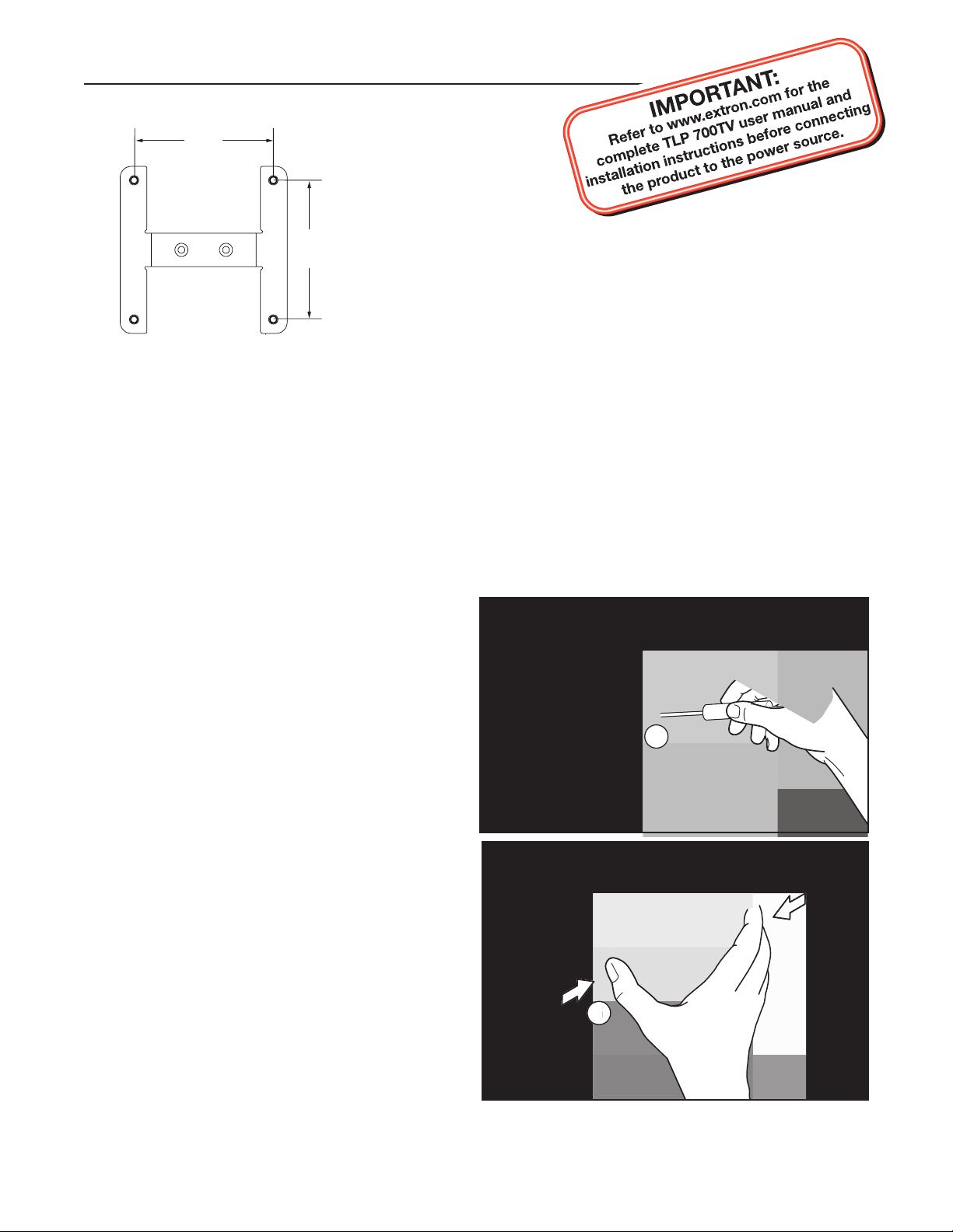
5. At the bottom, the two plastic cover plates for the
stand are held together by a Phillips head screw
near the base. Remove the screw in the recessed slot
at the front of the stand, close to the base.
The third-party VESA mounting kit must be attached to a wall stud to support the weight of the mounting
arm and the TLP 700TV unit.
At the top, the two plastic plates covering the stand
6.
are held together by four locking tabs on the back
cover plate fitting into four slots on the front cover
plate. Squeeze the sides of the front plate at the top
so that the tabs are no longer seated in the slots.
68-1792-01
Rev. A 08 09
Page 2
VM 700T Mounting Kit Installation Guide, Continued
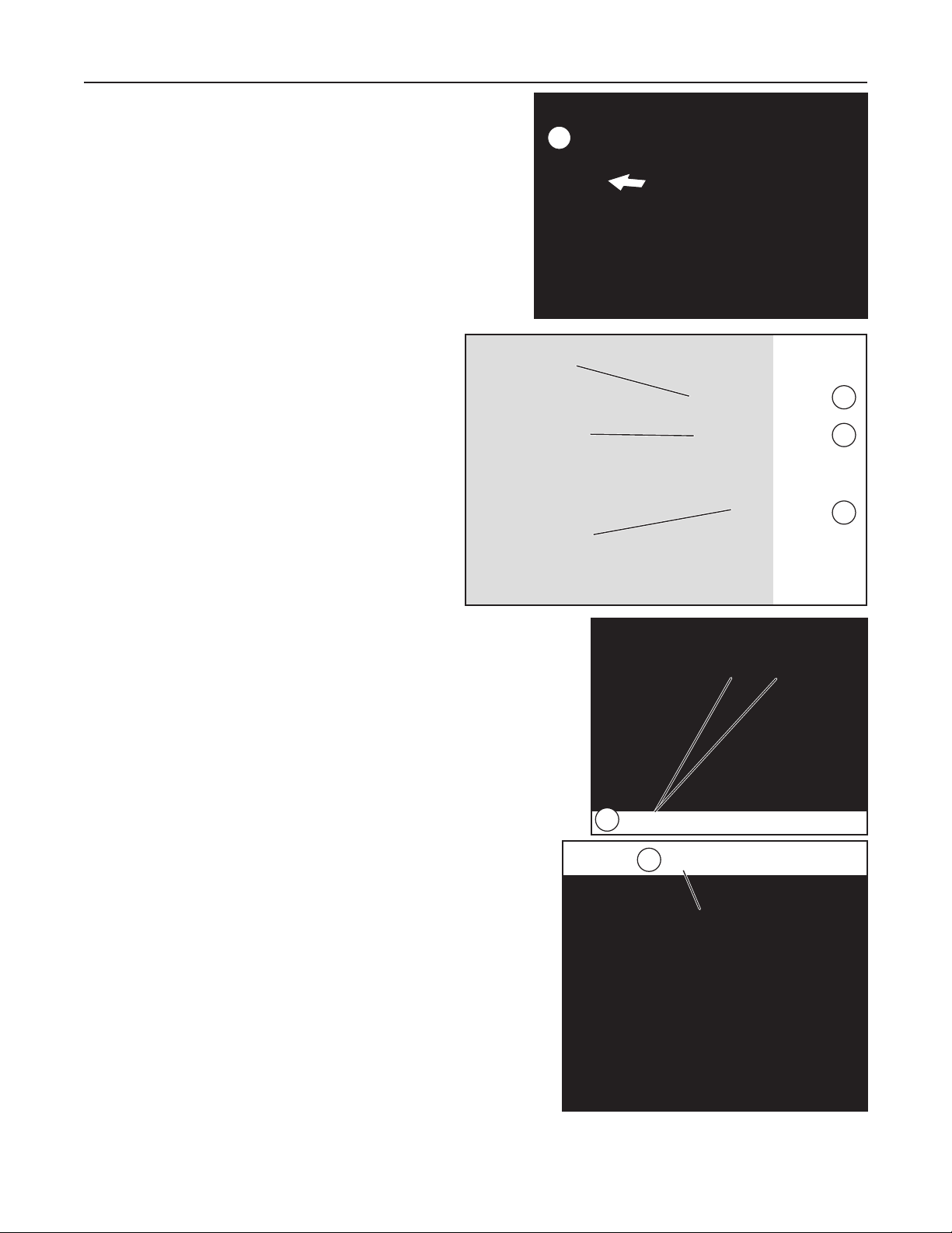
Remove back cover.
7
Remove (2) Screws
11
Adjust bracket and thread cables through.
12
Remove Snake-skin Cover
Remove (cut) Plastic Tie
Remove all Cables
from Base
10
8
9
7. Remove the back cover to reveal the metal stand and the
cables connecting the circuit board in the base to the touch
panel screen.
. Cut the plastic tie holding the cables to the metal
8
stand.
9. Disconnect the power, LAN, audio, LED, and two
BNC cables from the circuit board in the base.
Remove the snake‑skin cover protecting the
10.
cables.
Tilt the screen down to reveal the Phillips head screws securing the
11.
screen to the hinged bracket at the top of the stand. Remove the
screws and save them for use with the VM 700T VESA mounting kit.
N
Save the two screws for use with the VM 700T mounting kit.
12. Thread the cables through the gap between the top bracket and
the stand. Place the screen, face down, on a soft cloth.
If it is difficult to fit the BNC connectors through the space
T
between the top bracket and the stand, adjust the angle of the
bracket to make the space as large as possible.
Page 3

V
Remove (3) Screws
13
PowerLAN S video
Input
17
16
Replace Molding
SECTION A–A
Ridges
Smooth
Power Supply
Output Cord
A A
3/16”
(5 mm) Max.
LED Audio Power
14
13. Remove and save the three Phillips head screws holding the plastic
molding to the back of the screen.
14.
Disconnect the audio, LED, and power cables from the back panel of
the screen.
The audio cables are the black and white pair, wound around a •
ferrite core.
The power cables are the red and black pair, terminated with a •
blue, 2‑pole captive screw connector.
The LED cables are the black and white pair, without a ferrite core.•
N
N
15. Replace the orange 2‑pole captive screw connector on the provided power supply with the blue connector from
C
16.
None of the cables that are connected with a plastic tie should be
disconnected.
Save the blue power cable connector for later use.
the power cable disconnected in step 14.
The power supply provided with the TLP 700TV is intended for use with the power supply input in the
base. In order to use the power supply with the rear panel power input the captive screw connector must be
replaced.
Thread the cable from the power supply through the slot in the plastic
molding and connect it to the direct input captive screw input on the rear
panel.
17. Thread the remaining cables from the rear panel (2 BNC and 1 LAN) through
the slot in the plastic molding. Reattach the molding to the back of the screen,
using the three screws saved from step 13.
Page 4

Extron USA - West
Headquarters
+800.633.9876
Inside USA / Canada Only
+1.714 .491.1500
+1.714 .491.1517 FAX
Extron USA - East
+800.633.9876
Inside USA / Canada Only
+1.919.863.1794
+1.919.863.1797 FA X
Extron Europe
+800.3987.6673
Inside Europe Only
+31.33.453.4040
+31.33.453.4050 FAX
Extron Asia
+800.7339.8766
Inside Asia Only
+65.6383.4400
+65.6383.4664 FAX
Extron Japan
+81.3.3511.7655
+81.3.3511.7656 FAX
Extron China
+400.883.1568
Inside China Only
+86.21.3760.1568
+86.21.3760.1566 FAX
Extron Middle East
+971.4.2991800
+971.4.2991880 FAX
VM 700T Mounting Kit Installation Guide, Continued
21
20
19
18
18. Hold the remaining cables towards the bottom of the
recess in the plastic moulding.
19. Holding the VM 700T mounting plate at a slight angle,
slide the center bar under the cables and into the recess, so
that it sits firmly at the bottom of the recess.
Secure the bracket to the screen, using the two screws saved from
20.
step 11.
Attach the mounting plate to the bracket that was wall‑mounted in
21.
step 2.
. Plug in the rear panel cables, as required.
22
N
When the base is removed from the TLP 700TV, video connections are via BNC connectors, and there is no audio
input.
© 2009 Extron Electronics. All rights reserved.
 Loading...