

Page 1
User’s Guide
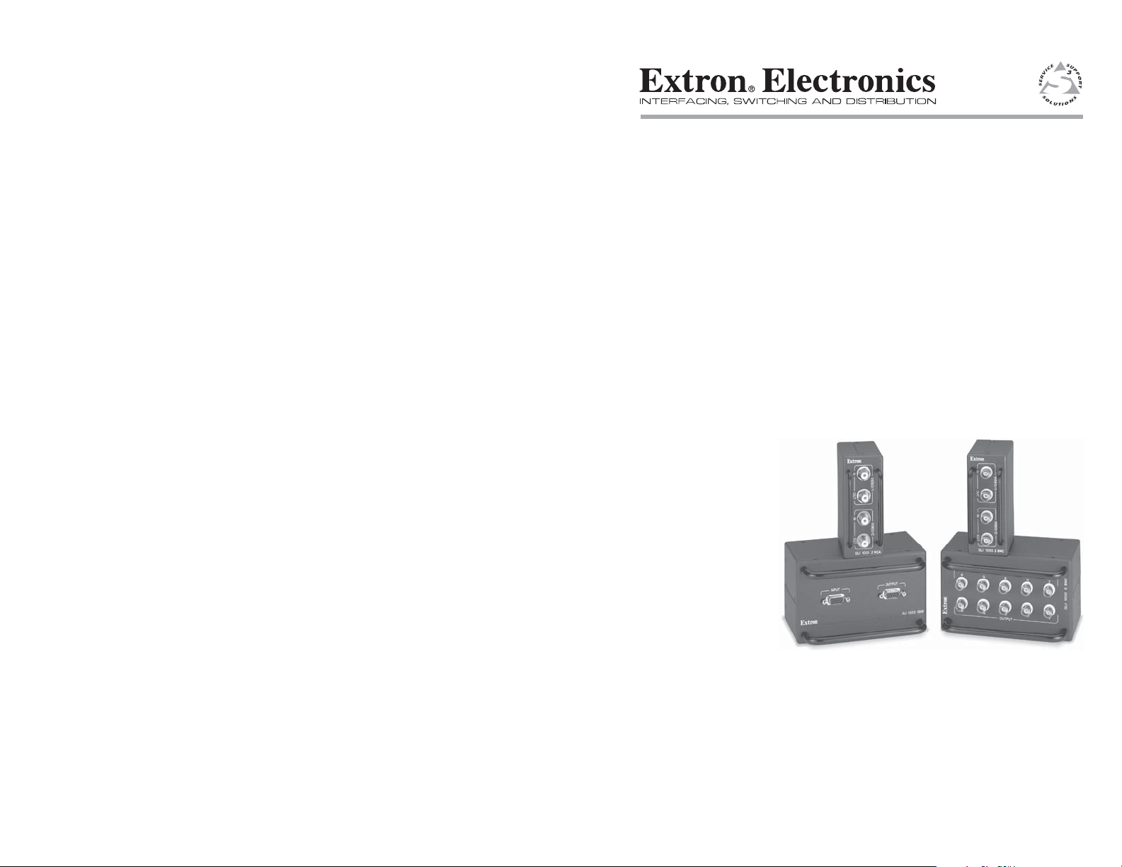
GLI 1000 5BNC
GLI 1000 2BNC
GLI 1000 2RCA
GLI 1000 15HD
Passive Ground Loop Inhibitors
68-571-01 Rev. B
Printed in the USA
09 02
Page 2
Installation
Introduction
The GLI 1000 family of ground loop inhibitors (GLIs) eliminates the
hum bars and common mode noise associated with improper video
equipment grounding (figure 1). Ground loop problems can be caused
by using AC power sources with different ground levels or by plugging
high current equipment into the same power source as video equipment.
Figure 1 — Hum bars
The GLI 1000 family consists of the following four models:
• GLI 1000 5BNC — The GLI 1000 5BNC has five female BNCs on the
input and five on the output. This GLI cleans ground noise from RGB
or component video. It can also be used for one or two S-video
signals or up to five composite video signals.
• GLI 1000 15HD — The GLI 1000 15HD has a female 15HD connector
on the input and another on the output. This GLI inhibits ground
loops on VGA, XGA, and UXGA video. With an adapter cable, it can
be used for S-video signals or composite video signals.
• GLI 1000 2RCA — The GLI 1000 2RCA has two female RCA
connectors on the input and two on the output. This GLI removes
ground problems from one or two composite video signals. With an
adapter, it can also be used with S-video.
• GLI 1000 2BNC — The GLI 1000 2BNC has two female BNCs on the
input and two on the output. This GLI inhibits ground loops on
S-video. It can also be used for one or two composite video signals.
The passive, non-powered, GLIs have a 1.0 GHz (-3dB) bandwidth, and
can handle any video format. Guardrails protect the GLI connectors
from damage caused by rough handling. With optional mounting
brackets, the GLIs can be mounted to a projector mount or under a desk.
The GLIs can also be mounted to optional 1U or 2U rack panels.
Installation
Installation consists of mounting the GLI and making connections.
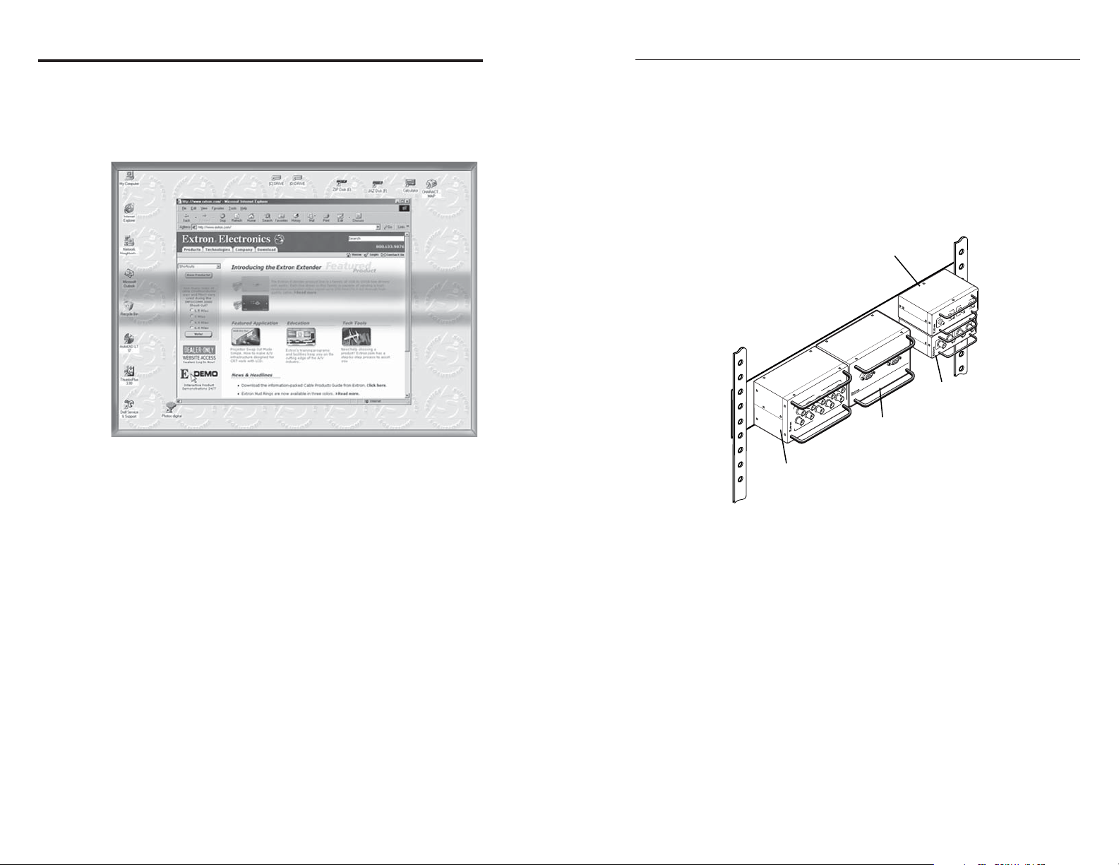
Rack mounting
The GLI 1000 5BNC and GLI 1000 15HD are one third of a standard rack
in width and 2U high. Up to three of these units can be mounted to the
rear of a flat 2U rack panel (figure 2) or the front of a recessed 2U rack
panel using four 6-32 x 3/8 screws.
Extron
GLI 1000 5BNC
Ground Loop Inhibitor
Figure 2 — Rack mounting the GLI Inhibitor
The GLI 1000 2RCA and GLI 1000 2BNC are a quarter of a rack in width
and 1U high. Up to four of these units can be mounted to the rear of the
flat1U rack panel or the front of the recessed 1U rack panel.
A mix of larger and smaller GLIs can be mounted on either 2U panel, for
example, two GLI 1000 15HDs, a GLI 1000 2RCA, and a GLI 1000 2BNC.
Another example is one GLI 1000 5BNC and four GLI 1000 2BNCs.
Bracket mounting
Secure the optional mounting bracket to the GLI using four #8 machine
screws already installed in the side of the GLI. Secure the GLI to a
projector mount or other surface by inserting the mounting screw
through the bracket’s slotted hole (figure 3).
Under table mounting
1. Secure both optional mounting brackets to the GLI with eight #8
machine screws already installed in the side of the GLI (figure 4).
GLI 1000 2RCA
GLI 1000 5BNC
HV
T
U
P
IN
B
G
R
HV
B
T
U
P
T
U
O
G
R
Extron
T
U
P
T
U
O
D
H
5
1
0
0
0
I 1
L
G
T
U
P
IN
Extron
GLI 1000 15HD
/C
O
E
D
I
V
GLI 1000 2RCA
T
U
P
T
U
/Y
O
O
E
ID
V
T
U
P
N
I
IDEO/C
V
GLI 1000 2BNC
PUT
/Y
OUT
VIDEO
T
INPU
Extron
GLI 1000 2BNC
2
GLI 1000 • Installation 3GLI 1000 • Installation
Page 3

Installation
Input
GLI 1000 15HD
Ceiling
Figure 3 — Bracket mounting a GLI
Mounting Screws (2 Plcs)
Projector
Mounting
Bracket
INPUT OUTPUT
Mounting
Bolt
Each Side
Drill pilot holes
__
3/32" (2.4mm) diam.
1/4" (6.3mm) deep.
5. Align the mounting screws with the brackets’ slots and place the
GLI against the surface, with the screws through the bracket slots.
6. Slide the inhibitor slightly forward or back, then tighten all four
screws to secure the inhibitor in place.
Connections
Install the GLI near the display rather than near the source device.
GLI 1000 5BNC
Input connectors — Connect an RGBHV, RGBS, RGsB, RsGsBs,
1
component video source, one or two S-video sources, or up to five
composite video sources to the five Input BNCs (figure 5).
1
RGBHV
RGBHV
INPUT
OUTPUT
GLI 1000 5BNC
2
5 5 6 6 7 7 8 8
GLI 1000 5BNC
3 4
INPUT
GLI 1000 15HD
OUTPUT
GLI 1000 15HD
T
U
P
T
U
O
D
H
15
0
0
0
I 1
L
T
U
P
IN
G
VIDEO/Y
INPUT
GLI 1000 2BNC
VIDEO/C
OUTPUT
GLI 1000 2BNC
VIDEO/Y
INPUT
VIDEO/C
OUTPUT
GLI 1000 2RCA
GLI 1000 2RCA
Figure 5 — GLI 1000 connections
#8 Screws (4 Plcs)
Each Side
Table/
Wall-mount
Bracket
Output connectors — Connect an RGBHV, RGBS, RGsB, RsGsBs,
2
or component video display, one or two S-video display, or up to
five composite video displays to the five Output BNCs.
Figure 4 — Table mounting a GLI
GLI 1000 15HD
2. Hold the GLI with the attached brackets against the underside of
the table or other furniture. Mark the location of the screw holes.
3. Drill 3/32” (2 mm) diameter pilot holes, 1/4” (6.3 mm) deep in the
mounting surface at the marked screw locations.
Input connectors — Connect an RGBHV, RGBS, RGsB, RsGsBs, or
3
component video source to the Input 15HD connector or with an
optional SY-VGA cable, connect one or two S-video sources, or up
to five composite video sources.
4. Insert #8 wood screws into the four pilot holes. Tighten each screw
into the surface until just less than 1/4” of the screw protrudes.
4
GLI 1000 • Installation and Operation 5GLI 1000 • Installation
Page 4

Operation
Output connectors — Connect an RGBHV, RGBS, RGsB, RsGsBs,
4
component video display to the Output 15HD connector or with
an optional SY-VGA cable, connect one or two S-video display, or
up to five composite video displays
GLI 1000 2BNC
Video/Y and Video/C Input connectors — Connect an S-video
5
source or two composite video sources to the two Input BNCs
(figure 5).
Video/Y and Video/C Output connectors — Connect an S-video
6
display or two composite video displays to the two Output BNCs.
GLI 1000 2RCA
Video/Y and Video/C Input connectors — Connect an S-video
7
source or two composite video sources to the two Input RCA
connectors.
Video/Y and Video/C Output connectors — Connect an S-video
8
display or two composite video displays to the two Output RCA
connectors.
Specifications
Video
Gain ............................................... Unity
Bandwidth .................................... 1.0 GHz (-3dB)
CMRR ............................................ -60 dB @ 60Hz/50Hz
Video input
Number/signal type
GLI 1000 15HD ................. 1 analog VGA-XGA, RGBHV, RGBS, RGsB,
RsGsBs, or component video; or 2 S-video and 1
NTSC/PAL/SECAM composite video; or 1
S-video and 3 NTSC/PAL/SECAM composite
video; or 5 NTSC/PAL/SECAM composite video
GLI 1000 5BNC ................ 1 analog RGBHV, RGBS, RGsB, RsGsBs, or
component video; or 2 S-video and 1
NTSC/PAL/SECAM composite video; or 1
S-video and 3 NTSC/PAL/SECAM composite
video; or 5 NTSC/PAL/SECAM composite video
GLI 1000 2BNC/2RCA ... 1 NTSC/PAL/SECAM S-video or 2
NTSC/PAL/SECAM composite video
Connectors
GLI 1000 15HD ................. 1 female 15HD connector
GLI 1000 5BNC ................ 5 female BNCs
GLI 1000 2BNC ................ 2 female BNCs
GLI 1000 2RCA ................ 2 female RCA connectors
Minimum/maximum level(s) .... Analog -10.0V to +10.0V p-p with no offset
Impedance .................................... 75 ohms
Horizontal frequency .................. 10 kHz to 200 kHz
Vertical frequency ....................... 15 Hz to 180 Hz
Video output
Number/signal type
GLI 1000 15HD ................. 1 analog VGA-UXGA, RGBHV, RGBS, RGsB,
RsGsBs, or component video; or 2 S-video and 1
NTSC/PAL/SECAM composite video; or 1
S-video and 3 NTSC/PAL/SECAM composite
video; or 5 NTSC/PAL/SECAM composite video
GLI 1000 5BNC ................ 1 analog RGBHV, RGBS, RGsB, RsGsBs, or
component video; or 2 S-video and 1
NTSC/PAL/SECAM composite video; or 1
S-video and 3 NTSC/PAL/SECAM composite
video; or 5 NTSC/PAL/SECAM composite video
GLI 1000 2BNC/ 2RCA .. 1 S-video or 2 composite video
Connectors
GLI 1000 15HD ................. 1 female 15HD connector
GLI 1000 5BNC ................ 5 female BNCs
GLI 1000 2BNC ................ 2 female BNCs
GLI 1000 2RCA ................ 2 female RCA connector
Minimum/maximum level(s) .... Analog -10.0V to 10.0V p-p with no offset
Impedance .................................... 75 ohms
Return loss .................................... Better than 30dB up to 100 MHz
Sync
Input/Output type
GLI 1000 15HD, 5BNC .... RGBHV, RGBS, RsGsBs, RGsB
Standards ...................................... NTSC 3.58, NTSC 4.43, PAL, SECAM
Input level ..................................... 0.5V to 5.0V p-p
Output level .................................. TTL: 0V to 10.0V p-p
Input/Output impedance .......... 75 ohms
Polarity .......................................... Follows input
General
Power ............................................. Non-powered
6
GLI 1000 • Operation 7GLI 1000 • Operation
Page 5

Temperature/humidity .............. Storage -40° to +158°F (-40° to +70°C) / 10% to
90%, non-condensing
Operating +32° to +122°F (0° to +50°C) / 10% to
90%, non-condensing
Rack mount
GLI 1000 15HD/5BNC .... Yes, with optional flat or recessed 2U rack panel
GLI 1000 2BNC/2RCA ... Yes, with optional flat or recessed 1U rack panel
Also table and projector bracket mountable with
optional brackets
Enclosure type .............................. Metal
Enclosure dimensions
GLI 1000 15HD/5BNC .... 5.6” H x 3.75” W x 4.1” D, 14.3 cm H x 9.5 cm W
x 10.4 cm D (Depth excludes guardrails)
GLI 1000 2BNC/2RCA ... 4.25” H x 1.75” W x 3.8” D, 10.8 cm H x 4.4 cm W
x 9.7 cm D (Depth excludes guardrails)
Protective guards ......................... 1.0” H
Shipping weight
GLI 1000 5BNC ................ 1.5 lbs (0.6 kg)
GLI 1000 15HD ................. 1.4 lbs (0.6 kg)
GLI 1000 2BNC/2RCA ... 0.7 lb (0.3 kg)
Vibration ....................................... ISTA/NSTA 1A in carton (International Safe
Transit Association)
Listings .......................................... UL
Compliances ................................. CE
MTBF ............................................. 30,000 hours
Warranty ....................................... 3 years parts and labor
Specifications are subject to change without notice.
Optional Accessories
• Mini bracket furniture mount 70-212-01
• 1U recessed vertical rack 70-213-01
• 2U recessed vertical rack plate 70-214-01
• 1U flat vertical rack plate 70-215-01
• 2U flat vertical rack plate 70-216-01
• GLI 1000 projector mount 70-217-01
Extron Electronics, USA
1230 South Lewis Street
Anaheim, CA 92805
USA
www.extron.com
714.491.1500
Fax 714.491.1517
© 2002 Extron Electronics. All rights reserved.
Extron Electronics, Europe
Beeldschermweg 6C
3821 AH Amersfoort
The Netherlands
+31.33.453.4040
Fax +31.33.453.4050
Extron Electronics, Asia
135 Joo Seng Road, #04-01
PM Industrial Building
Singapore 368363
+65.6383.4400
Fax +65.6383.4664
Extron Electronics, Japan
Daisan DMJ Building 6F
3-9-1 Kudan Minami
Chiyoda-ku, Tokyo 102-0074 Japan
+81.3.3511.7655
Fax +81.3.3511.7656
 Loading...