

Page 1

Summit Family Hardware
Installation Guide
for Switches Supported by ExtremeXOS 16 or Earlier
121141-03
Published October 2017
Page 2

Copyright © 2017 Extreme Networks, Inc. All rights reserved.
Legal Notice
Extreme Networks, Inc. reserves the right to make changes in specifications and other information
contained in this document and its website without prior notice. The reader should in all cases
consult representatives of Extreme Networks to determine whether any such changes have been
made.
The hardware, firmware, software or any specifications described or referred to in this document
are subject to change without notice.
Trademarks
Extreme Networks and the Extreme Networks logo are trademarks or registered trademarks of
Extreme Networks, Inc. in the United States and/or other countries.
All other names (including any product names) mentioned in this document are the property of
their respective owners and may be trademarks or registered trademarks of their respective
companies/owners.
For additional information on Extreme Networks trademarks, please see:
www.extremenetworks.com/company/legal/trademarks
Software Licensing
Some software files have been licensed under certain open source or third-party licenses. Enduser license agreements and open source declarations can be found at:
www.extremenetworks.com/support/policies/software-licensing
Support
For product support, phone the Global Technical Assistance Center (GTAC) at 1-800-998-2408
(toll-free in U.S. and Canada) or +1-408-579-2826. For the support phone number in other
countries, visit: http://www.extremenetworks.com/support/contact/
For product documentation online, visit: https://www.extremenetworks.com/documentation/
Page 3

Table of Contents
Preface......................................................................................................................................... 7
Audience....................................................................................................................................................................................7
Conventions.............................................................................................................................................................................7
Providing Feedback to Us................................................................................................................................................ 9
Getting Help............................................................................................................................................................................ 9
Related Publications.......................................................................................................................................................... 10
Chapter 1: Summit Switches.....................................................................................................11
Overview of the Summit Switches.............................................................................................................................. 12
Summit X150 Series Switches........................................................................................................................................13
Summit X250e Series Switches....................................................................................................................................18
Summit X350 Series Switches...................................................................................................................................... 31
Summit X430 Series Switches.....................................................................................................................................36
Summit X440 Series Switches.....................................................................................................................................42
Summit X450, X450a, and X450e Series Switches.......................................................................................... 66
Summit X450-G2 Series Switches.............................................................................................................................88
Summit X460 Series Switches.....................................................................................................................................99
Summit X460-G2 Series Switches........................................................................................................................... 107
Summit X480 Series Switches.....................................................................................................................................121
Summit X650 Series Switches....................................................................................................................................126
Summit X670 Series Switches....................................................................................................................................129
Summit X670-G2 Series Switches............................................................................................................................135
Summit X770 Series Switches....................................................................................................................................139
Pluggable Interfaces for Summit Switches.......................................................................................................... 143
Chapter 2: Power Supplies for Use with Summit Switches..............................................145
External Power Supplies for Summit Switches..................................................................................................145
Replaceable Internal Power Supplies for Summit Switches........................................................................ 159
Chapter 3: Option Cards and Versatile Interface Modules...............................................165
Summit XGM-2xn Option Card.................................................................................................................................. 166
Summit XGM2-2xn Option Card................................................................................................................................167
Summit XGM2-2xf Option Card.................................................................................................................................168
Summit XGM2-2sf Option Card................................................................................................................................. 169
Summit XGM2-2bt Option Card................................................................................................................................ 170
Versatile Interface Modules for the Summit X480 Series Switches.........................................................170
Versatile Interface Modules for the Summit X650 Series Switches......................................................... 173
Optional Ports for the Summit X460 Series Switches....................................................................................177
Summit X460 Series Stacking Modules................................................................................................................ 180
Optional Ports for the X460-G2 Series Switches.............................................................................................180
VIM4-40G4X Versatile Interface Module for the Summit X670 Switch................................................ 184
Chapter 4: Site Preparation.................................................................................................. 186
Planning Your Site............................................................................................................................................................ 186
Operating Environment Requirements...................................................................................................................187
Rack Specifications and Recommendations........................................................................................................ 191
Evaluating and Meeting Cable Requirements.....................................................................................................192
Meeting Power Requirements.................................................................................................................................... 198
Following Applicable Industry Standards.............................................................................................................201
Summit Family Hardware Installation Guide 3
Page 4

Table of Contents
Chapter 5: Building Stacks...................................................................................................202
Introduction to Stacking.............................................................................................................................................. 202
Planning to Create Your Stack....................................................................................................................................214
Setting up the Physical Stack....................................................................................................................................239
Chapter 6: Installing Summit Switches...............................................................................263
Safety Considerations for Installing Switches....................................................................................................263
Pre-installation Requirements................................................................................................................................... 264
Installing a Summit Family Switch...........................................................................................................................265
Installing Internal Power Supplies............................................................................................................................285
Connecting Network Interface Cables....................................................................................................................312
Performing Initial Management Tasks..................................................................................................................... 313
Chapter 7: Installing Summit External Power Supplies.................................................... 317
Safety Considerations for Installing Power Supplies.......................................................................................317
Pre-installation Requirements.....................................................................................................................................318
Installing an EPS-150DC External Power Module (with EPS-T2)...............................................................318
Installing an EPS-160 External Power Module (with EPS-T).......................................................................323
Installing an EPS-500 External Power Supply Unit.........................................................................................326
Installing an EPS-600LS External Power Module............................................................................................ 328
Installing an EPS-C2 Power Supply.........................................................................................................................333
Installing an EPS-LD External Power Supply...................................................................................................... 341
Installing an STK-RPS-150PS Redundant Power Supply..............................................................................344
Installing an RPS-500p Redundant Power Supply......................................................................................... 349
Chapter 8: Installing Port Option Cards and VIMs............................................................354
Installing a Summit Port Option Card................................................................................................................... 354
Installing an Option Card in Slot B of a Summit X460 Series Switch....................................................357
Installing a Versatile Interface Module in a Summit X460, X480, X650, or X670 Series
Switch....................................................................................................................................................................................358
Installing a Versatile Interface Module or Clock Module in a Summit X460-G2 Series Switch.360
Chapter 9: Replacing AC Power Supplies..........................................................................362
Replacing a Summit 300 W AC Power Supply.................................................................................................362
Replacing a Summit 715 W AC Power Supply...................................................................................................364
Replacing a Summit 450 W or 550 W AC Power Supply...........................................................................366
Replacing a Summit 750 W AC Power Supply.................................................................................................368
Replacing a Summit 850 W AC Power Supply................................................................................................. 372
Replacing a Summit 1100 W AC Power Supply................................................................................................ 374
Removing an EPS-LD or EPS-500 Power Supply........................................................................................... 376
Removing an EPS-160 Power Supply from an EPS-T.................................................................................... 376
Removing an EPS-600LS Power Module.............................................................................................................377
Removing an STK-RPS-150PS Redundant Power Supply............................................................................377
Chapter 10: Replacing DC Power Supplies........................................................................ 378
Replacing a Summit 300 W DC Power Supply.................................................................................................378
Replacing a Summit 450 W or 550 W DC Power Supply...........................................................................384
Replacing a Summit 850 W DC Power Supply..................................................................................................391
Removing an EPS-150DC Power Module from an EPS-T2 Tray................................................................395
Chapter 11: Replacing Fan Modules.................................................................................... 396
Pre-Installation Requirements................................................................................................................................... 396
Summit Family Hardware Installation Guide 4
Page 5

Table of Contents
Airflow Direction Requirements............................................................................................................................... 396
Replacing a Fan Module...............................................................................................................................................396
Chapter 12: Replacing Port Option Cards and VIMs.........................................................398
Replacing a Stacking Module or Option Card in Slot B of a Summit X460 Series Switch......... 398
Replacing an XGM3/XGM3S Series Port Option Card in a Summit X460 Series Switch.............399
Replacing a Versatile Interface Module (VIM) in a Summit X480, X650 or X670 Series
Switch...................................................................................................................................................................................400
Replacing an XGM or XGM2 Series Port Option Card...................................................................................402
Replacing a Versatile Interface Module or Clock Module in a Summit X460-G2 Series
Switch................................................................................................................................................................................... 403
Chapter 13: Removing Summit Switches........................................................................... 405
Removing an AC Power Supply...............................................................................................................................405
Removing a DC Power Supply................................................................................................................................. 406
Removing a Switch from a Rack..............................................................................................................................407
Appendix A: Safety Information......................................................................................... 409
Considerations Before Installing..............................................................................................................................409
General Safety Precautions.........................................................................................................................................410
Maintenance Safety...........................................................................................................................................................411
Cable Routing for LAN Systems.................................................................................................................................411
Installing Power Supply Units and Connecting Power...................................................................................412
Selecting Power Supply Cords................................................................................................................................... 413
Battery Replacement and Disposal.........................................................................................................................414
Battery Warning - Taiwan.............................................................................................................................................414
Fiber Optic Ports and Optical Safety..................................................................................................................... 414
Sicherheitshinweise..........................................................................................................................................................415
Überlegungen vor der Installation............................................................................................................................416
Allgemeine Sicherheitshinweise................................................................................................................................416
Sicherheit bei Wartungsarbeiten...............................................................................................................................417
Kabelverlegung für LAN-Systeme............................................................................................................................417
Installation der Netzteile und Netzanschluss......................................................................................................418
Auswahl der Netzkabel.................................................................................................................................................420
Wechseln und Entsorgen der Batterie..................................................................................................................420
LWL-Ports und optische Sicherheit....................................................................................................................... 420
Konformität von GBIC, SFP (Mini-GBIC), QSFP+, XENPAK und XFP..................................................... 421
Mögliche Netzanschlussgerät- und Lüftereinsatz-Konfigurationen für X770-32q..........................422
Appendix B: Technical Specifications................................................................................ 424
Summit X150 Series Switches Technical Specifications............................................................................... 425
Summit X250e Series Switches Technical Specifications............................................................................429
Summit X350 Series Switches Technical Specifications..............................................................................436
Summit X430 Series Switches Technical Specifications..............................................................................439
Summit X440 Series Switches Technical Specifications............................................................................. 444
Summit X450 Series Switches Technical Specifications..............................................................................454
Summit X450a Series Switches Technical Specifications........................................................................... 456
Summit X450e Series Switches Technical Specifications........................................................................... 462
Summit X450-G2 Series Switches Technical Specifications......................................................................466
Summit X460 Series Switches Technical Specifications..............................................................................472
Summit X460-G2 Series Switches Technical Specifications......................................................................479
Summit X480 Series Switches Technical Specifications..............................................................................487
Summit Family Hardware Installation Guide 5
Page 6

Table of Contents
Summit X650 Series Switches Technical Specifications..............................................................................499
Summit X670 Series Switches Technical Specifications..............................................................................509
Summit X670-G2 Series Switches Technical Specifications........................................................................515
Summit X770 Series Switches Technical Specifications................................................................................519
STK-RPS-150PS and RPS Shelves Technical Specifications........................................................................523
Summit 300 W Power Supplies Technical Specifications............................................................................525
Summit 350 W Power Supplies Technical Specifications............................................................................527
Summit 450 W Power Supplies Technical Specifications............................................................................528
Summit 550 W Power Supplies Technical Specifications........................................................................... 530
Summit 550 W Power Supplies for X670-G2 Switches.................................................................................531
Summit 715 W Power Supplies Technical Specifications..............................................................................533
Summit 750 W Power Supplies Technical Specifications............................................................................534
Summit 850 W Power Supplies Technical Specifications............................................................................535
Summit 1100 W Power Supplies Technical Specifications...........................................................................536
Summit External Power Supplies Technical Specifications.........................................................................537
EPS-C2 Redundant Power Supply Technical Specifications....................................................................... 541
RPS-500p Redundant Power Supply Technical Specifications................................................................542
Power Cord Requirements for AC-Powered Switches and AC Power Supplies...............................543
Console Connector Pinouts........................................................................................................................................544
Taiwan Warnings..............................................................................................................................................................546
Japan (VCCI Class A).................................................................................................................................................... 546
Korea EMC Statement................................................................................................................................................... 547
Glossary.........................................................................................................................................548
Index........................................................................................................................................ 552
Summit Family Hardware Installation Guide 6
Page 7

Preface
This guide provides the instructions and supporting information needed to install the following Extreme
Networks® Summit® family switches:
Summit X150 Series Switches on page 13
•
Summit X250e Series Switches on page 18
•
Summit X350 Series Switches on page 31
•
Summit X430 Series Switches on page 36
•
Summit X440 Series Switches on page 42
•
Summit X450, X450a, and X450e Series Switches on page 66
•
Summit X450-G2 Series Switches on page 88
•
Summit X460 Series Switches on page 99
•
Summit X460-G2 Series Switches on page 107
•
Summit X480 Series Switches on page 121
•
Summit X650 Series Switches on page 126
•
Summit X670 Series Switches on page 129
•
Summit X670-G2 Series Switches on page 135
•
Summit X770 Series Switches on page 139
•
The guide includes information about site preparation, switch functionality, and switch operation.
Audience
This guide is intended for use by network administrators responsible for installing and setting up
network equipment. It assumes a basic working knowledge of:
Local area networks (LANs)
•
Ethernet concepts
•
Ethernet switching and bridging concepts
•
Routing concepts
•
SNMP (Simple Network Management Protocol)
•
Basic equipment installation procedures
•
See the ExtremeXOS 22.3 User Guide and the ExtremeXOS 22.3 Command Reference Guide for
information about configuring Summit switches.
Note
If the information in an installation note or release note shipped with your Extreme Networks
equipment diers from the information in this guide, follow the installation or release note.
Conventions
This section discusses the conventions used in this guide.
Summit Family Hardware Installation Guide 7
Page 8
Text Conventions
The following tables list text conventions that are used throughout this guide.
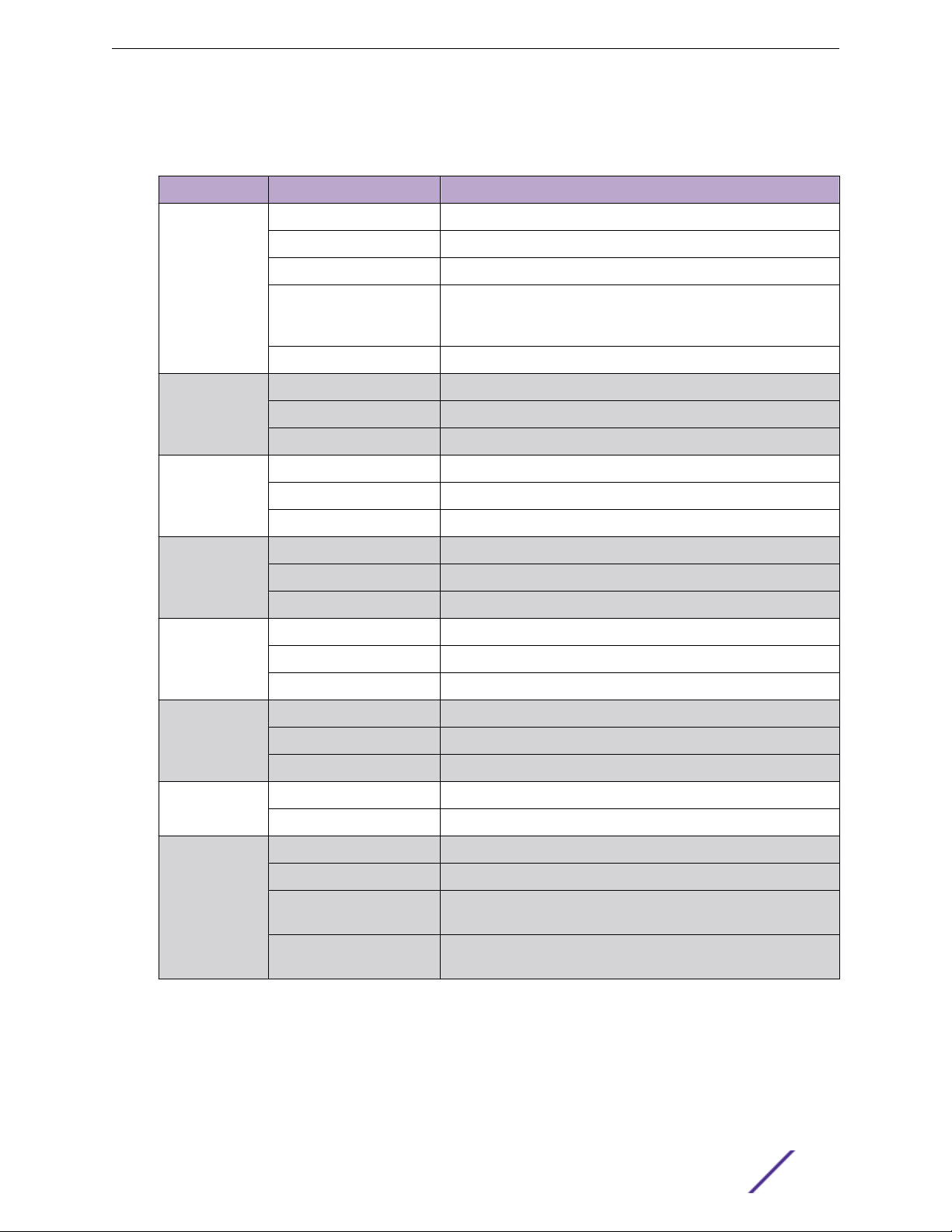
Table 1: Notice Icons
Icon Notice Type Alerts you to...
General Notice Helpful tips and notices for using the product.
Note Important features or instructions.
Caution Risk of personal injury, system damage, or loss of data.
Warning Risk of severe personal injury.
New This command or section is new for this release.
Preface
Table 2: Text Conventions
Convention Description
Screen displays
The words enter and
type
[Key] names Key names are written with brackets, such as [Return] or [Esc]. If you must press two
Words in italicized type Italics emphasize a point or denote new terms at the place where they are defined in
This typeface indicates command syntax, or represents information as it appears on the
screen.
When you see the word “enter” in this guide, you must type something, and then press
the Return or Enter key. Do not press the Return or Enter key when an instruction
simply says “type.”
or more keys simultaneously, the key names are linked with a plus sign (+). Example:
Press [Ctrl]+[Alt]+[Del]
the text. Italics are also used when referring to publication titles.
Platform-Dependent Conventions
Unless otherwise noted, all information applies to all platforms supported by ExtremeXOS® software,
which are the following:
ExtremeSwitching® switches
•
Summit® switches
•
SummitStack
•
™
When a feature or feature implementation applies to specific platforms, the specific platform is noted in
the heading for the section describing that implementation in the ExtremeXOS command
documentation (see the Extreme Documentation page at http://
documentation.extremenetworks.com). In many cases, although the command is available on all
Summit Family Hardware Installation Guide 8
Page 9

platforms, each platform uses specific keywords. These keywords specific to each platform are shown in
the Syntax Description and discussed in the Usage Guidelines sections.
Terminology
When features, functionality, or operation is specific to a switch family, such as ExtremeSwitching™ or
Summit®, the family name is used. Explanations about features and operations that are the same across
all product families simply refer to the product as the switch.
Providing Feedback to Us
We are always striving to improve our documentation and help you work better, so we want to hear
from you! We welcome all feedback but especially want to know about:
Content errors or confusing or conflicting information.
•
Ideas for improvements to our documentation so you can find the information you need faster.
•
Broken links or usability issues.
•
If you would like to provide feedback to the Extreme Networks Information Development team about
this document, please contact us using our short online feedback form. You can also email us directly at
internalinfodev@extremenetworks.com.
Preface
Getting Help
If you require assistance, contact Extreme Networks using one of the following methods:
GTAC (Global Technical Assistance Center) for Immediate Support
•
Phone: 1-800-998-2408 (toll-free in U.S. and Canada) or +1 408-579-2826. For the support
•
phone number in your country, visit: www.extremenetworks.com/support/contact
Email: support@extremenetworks.com. To expedite your message, enter the product name or
•
model number in the subject line.
GTAC Knowledge — Get on-demand and tested resolutions from the GTAC Knowledgebase, or
•
create a help case if you need more guidance.
The Hub — A forum for Extreme customers to connect with one another, get questions answered,
•
share ideas and feedback, and get problems solved. This community is monitored by Extreme
Networks employees, but is not intended to replace specific guidance from GTAC.
Support Portal — Manage cases, downloads, service contracts, product licensing, and training and
•
certifications.
Before contacting Extreme Networks for technical support, have the following information ready:
Your Extreme Networks service contract number and/or serial numbers for all involved Extreme
•
Networks products
A description of the failure
•
A description of any action(s) already taken to resolve the problem
•
A description of your network environment (such as layout, cable type, other relevant environmental
•
information)
Network load at the time of trouble (if known)
•
Summit Family Hardware Installation Guide 9
Page 10

The device history (for example, if you have returned the device before, or if this is a recurring
•
problem)
Any related RMA (Return Material Authorization) numbers
•
Related Publications
ExtremeSwitching X8, ExtremeSwitching, and E4G Hardware
Documentation
E4G Series Routers Hardware Installation Guide
•
Extreme Hardware/Software Compatibility and Recommendation Matrices
•
Extreme Networks Pluggable Transceivers Installation Guide
•
ExtremeSwitching X8 Series Switches Hardware Installation Guide
•
ExtremeXOS 16.2 User Guide
•
ExtremeXOS 16.2 Command Reference Guide
•
ExtremeSwitching and Summit Switches: Hardware Installation Guide for Switches Using
•
ExtremeXOS 21.1 or Later
Environmental Guidelines for ExtremeSwitching Products
•
Preface
Summit Family Hardware Installation Guide 10
Page 11

1 Summit Switches
Overview of the Summit Switches
Summit X150 Series Switches
Summit X250e Series Switches
Summit X350 Series Switches
Summit X430 Series Switches
Summit X440 Series Switches
Summit X450, X450a, and X450e Series Switches
Summit X450-G2 Series Switches
Summit X460 Series Switches
Summit X460-G2 Series Switches
Summit X480 Series Switches
Summit X650 Series Switches
Summit X670 Series Switches
Summit X670-G2 Series Switches
Summit X770 Series Switches
Pluggable Interfaces for Summit Switches
The Summit switches are compact enclosures 1.75 inches high (1 U). Each switch model provides
between 8 and 72 high-density copper or fiber optic ports operating at speeds up to 40 Gbps. Many
models also provide combination copper/fiber uplink ports. PoE connections and options for adding 10-
Gbps or 40-Gbps uplink connections are available on some models.
Many Summit switches include high-speed stacking interfaces that allow you to connect up to eight
switches into a single SummitStack management entity. Models are available for AC or DC power
connection; all switches make provision for redundant power supplies. Most models have connections
for optional external redundant power supplies: the Summit X450-G2 (PoE models), X460, X460-G2,
X480, X650, X670, X670-G2, and X770 switches provide two bays for pluggable power supplies.
Most models are available in versions that are compliant with the Trade Agreements Act (TAA); these
versions are identified by a -TAA sux on the model number. Functionally, the TAA-compliant models
are completely equivalent to the matching versions that are not TAA-compliant. In all feature
descriptions, references to a specific Summit switch model also apply to the equivalent TAA-compliant
model.
This document describes switches that are supported on ExtremeXOS version 16 and earlier. For
information about other ExtremeSwitching and Summit switches, refer to the ExtremeSwitching and
Summit Switches: Hardware Installation Guide for Switches Using ExtremeXOS 21.1 or Later.
The following sections contain general information about the switches:
Summit Family Hardware Installation Guide 11
Page 12

Summit X150 Series Switches on page 13
•
Summit X250e Series Switches on page 18
•
Summit X350 Series Switches on page 31
•
Summit X430 Series Switches on page 36
•
Summit X440 Series Switches on page 42
•
Summit X450, X450a, and X450e Series Switches on page 66
•
Summit X450-G2 Series Switches on page 88
•
Summit X460 Series Switches on page 99
•
Summit X460-G2 Series Switches on page 107
•
Summit X480 Series Switches on page 121
•
Summit X650 Series Switches on page 126
•
Summit X670 Series Switches on page 129
•
Summit X670-G2 Series Switches on page 135
•
Summit X770 Series Switches on page 139
•
Overview of the Summit Switches
Summit Switches
The following sections describe the Summit switches and summarize the features available in each
series.
Model numbers for the switches are in the following format:
<Series>-<number of front-panel I/O ports><port type><internal power supply type>
The number of ports ranges from 8 to 72.
•
The port type can be t (copper), p (copper providing PoE (Power over Ethernet)), q (QSFP+), or x
•
(fiber).
For models with integral power supplies, the power supply type can be AC (no designation) or DC.
•
Models with pluggable power supplies can accommodate either AC or DC supplies and have no
power designation in their model numbers.
Note
See the ExtremeXOS 22.3 User Guide and the ExtremeXOS 22.3 Command Reference Guide
for feature-specific information about the Summit switches and for information regarding
switch configuration.
Combination Ports and Failover
Summit switches provide 2, 4, or 12 uplink ports implemented as combination ports that pair a copper
port using RJ45 connectors with an optical port using LC connectors.
The copper port operates as an autonegotiating 10/100/1000BASE-T port. The optical port allows
Gigabit Ethernet uplink connections through Extreme Networks small form factor pluggable (SFP)
interface modules. See the individual switch descriptions for the port numbers of the combination ports
on each switch model.
Summit Family Hardware Installation Guide 12
Page 13

Summit Switches
Summit switches support automatic failover from an active fiber port to a copper backup or from an
active copper port to a fiber port. If one of the uplink connections fails, the Summit uplink connection
automatically fails over to the second connection. To set up a redundant link on a combination port,
connect the active 1000BASE-T and fiber links to both the RJ45 and SFP interfaces of that port.
Gigabit Ethernet uplink redundancy on the Summit switches follows these rules:
With both the SFP and 1000BASE-T interfaces connected on a combination port, only one interface
•
can be activated. The other is inactive.
If only one interface is connected, the switch activates the connected interface.
•
The switch determines whether the port uses the fiber or copper connection based on the order in
•
which the connectors are inserted into the switch. When the switch senses that an SFP and a copper
connector are inserted, the switch enables the uplink redundancy feature. For example, if you first
connect copper ports x and y on a switch, and then insert SFPs into ports x and y, the switch
assigns the copper ports as active ports and the fiber ports as redundant ports.
Hardware identifies when a link is lost and responds by swapping the primary and redundant ports to
maintain stability. After a failover occurs, the switch keeps the current port assignment until another
failure occurs or a user changes the assignment using the CLI. For more information about configuring
automatic failover on combination ports, see the ExtremeXOS 22.3 User Guide.
Summit X150 Series Switches
The Summit X150 series switches provide 24 or 48 fixed 10/100BASE-T Ethernet ports that deliver highdensity copper connectivity at 2.4 Gbps or 4.8 Gbps.
Models are available with PoE and without PoE. Each Summit X150 series switch has two combination
ports that provide 10/100/1000 BASE-T or SFP connectivity for 2 Gbps of copper or fiber connectivity.
A serial console port on the front panel allows you to connect a terminal and perform local
management. On the back of the switch, an Ethernet management port can be used to connect the
system to a parallel management network for administration. Alternatively, you can use an Ethernet
cable to connect this port directly to a laptop to view and locally manage the switch configurations.
The rear panel of the switch provides an AC power input socket and a redundant power connector. The
internal power supply operates from 100 VAC to 240 VAC. The switch automatically adjusts to the
supply voltage. The redundant power connector allows you to connect the switch to the EPS-160 or
EPS-500 external power supply. When a compatible external power supply is used with the Summit
X150 series switch, the internal and external power supplies are fully fault tolerant and load-sharing. If
one power supply fails, the other power supply will provide sucient power to operate the switch.
The Summit X150e series switches include the following switch models:
Summit X150-24t Switch Ports and Slots on page 14
•
Summit X150-24t-TAA switch
•
Summit X150-24p Switch Ports and Slots on page 15
•
Summit X150-24p-TAA switch
•
Summit Family Hardware Installation Guide 13
Page 14
Summit X150-48t Switch Ports and Slots on page 16
•
Summit X150-48t-TAA switch
•
Note
In the descriptions that follow, references to a Summit X150 series model number also apply
to the equivalent TAA-compliant switch version.
Summit X150 series switches require an ExtremeXOS version of at least 12.0.2.25 but not greater than
15.3.x.
Summit X150-24t Switch Ports and Slots
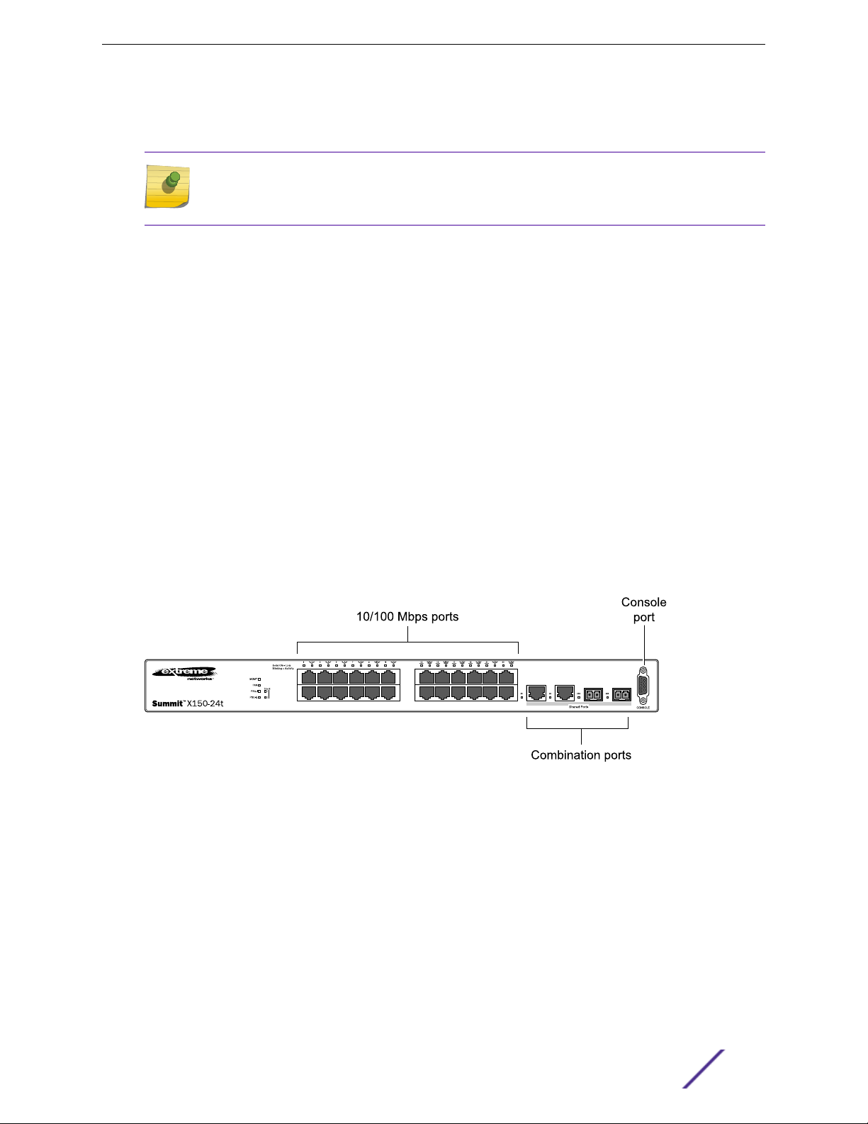
The front panel of the Summit X150-24t switch includes:
Twenty-four fixed autosensing 10/100BASE-T ports (ports 1–24) that provide 2.4 Gbps of high-
•
density copper connectivity.
Two combination ports (ports 25–26) using RJ45 connectors and SFPs to provide 2 Gbps of copper
•
or fiber connectivity.
Summit Switches
For more information about combination ports, see Combination Ports and Failover on page 12.
For information about SFPs, see the Extreme Networks Pluggable Transceivers Installation Guide.
LEDs to indicate port status and switch operating conditions.
•
For a description of the LEDs and their operation, see Summit X150 Series Switch LEDs on page 17.
Serial console port used to connect a terminal and perform local management.
•
Figure 1: Summit X150-24t Switch Front Panel
The rear panel of the Summit X150-24t switch (shown in Figure 2 on page 15) includes:
Ethernet management port with associated LEDs .
•
Redundant power input connector for optional connection to the EPS-160 External Power Module.
•
See EPS-160 External Power Module (with EPS-T) on page 150 for more information. The connecting
redundant power supply cable is shipped with the EPS-160 unit.
AC power input socket.
•
The internal AC power supply operates from 100 VAC to 240 VAC.
Summit Family Hardware Installation Guide 14
Page 15
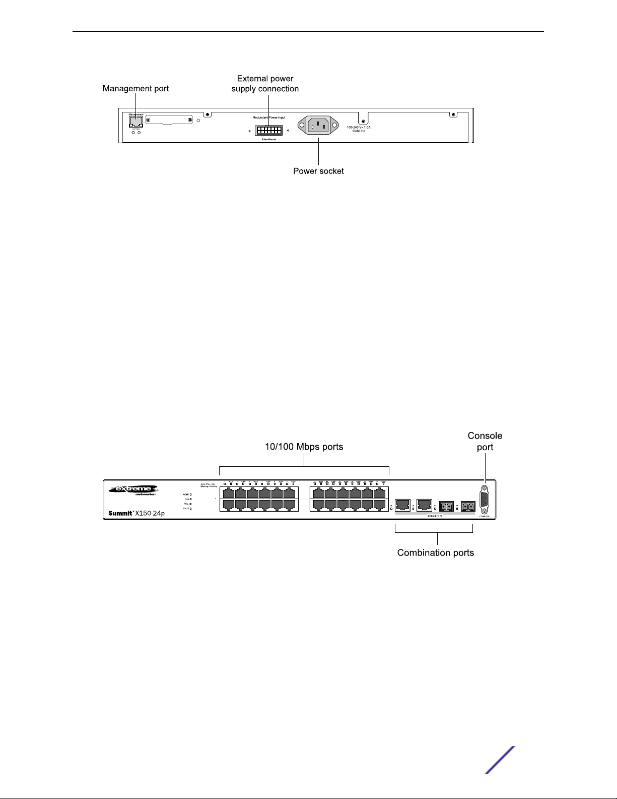
Figure 2: Summit X150-24t Switch Rear Panel
Summit X150-24p Switch Ports and Slots
The front panel of the Summit X150-24p switch includes:
Twenty-four fixed autosensing 10/100BASE-T PoE ports (ports 1–24). In addition to 4 Gbps of high-
•
density copper connectivity, these ports also provide a full 15.4 Watts of PoE per port.
Two combination ports (ports 25–26) using RJ45 connectors and SFPs to provide 2 Gbps of copper
•
or fiber connectivity.
Summit Switches
For more information about combination ports, see Combination Ports and Failover on page 12.
For information about SFPs, see the Extreme Networks Pluggable Transceivers Installation Guide.
LEDs to indicate port status and switch operating conditions.
•
For a description of the LEDs and their operation, see Summit X150 Series Switch LEDs on page 17.
Serial console port used to connect a terminal and perform local management.
•
Figure 3: Summit X150-24p Switch Front Panel
The rear panel of the Summit X150-24p switch includes:
Ethernet management port with associated LEDs.
•
Redundant power input connector for optional connection to the EPS-500 External Power Supply
•
(Model No. 10911) with full PoE power support.
The connecting redundant power supply cable is shipped with the EPS-500 unit. See EPS-500
External Power Supply Unit on page 151 for more information.
AC power input socket.
•
The internal AC power supply operates from 100 VAC to 240 VAC.
Summit Family Hardware Installation Guide 15
Page 16
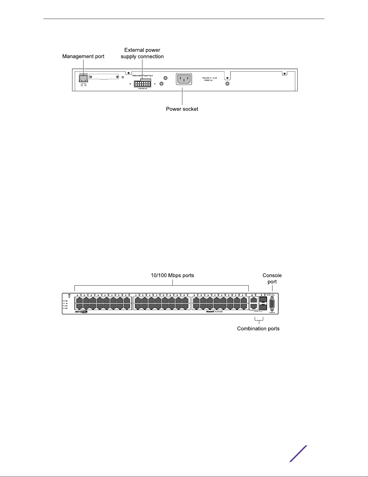
Figure 4: Summit X150-24p Switch Rear Panel
Summit X150-48t Switch Ports and Slots
The front panel of the Summit X150-48t switch includes:
Forty-eight fixed autosensing 10/100BASE-T ports (ports 1–48) that provide 4.8 Gbps of high-
•
density copper connectivity.
Two combination ports (ports 49–50) using RJ45 connectors and SFPs to provide 2 Gbps of copper
•
or fiber connectivity.
Summit Switches
For more information about combination ports, see Combination Ports and Failover on page 12.
For information about SFPs, see the Extreme Networks Pluggable Transceivers Installation Guide.
LEDs to indicate port status and switch operating conditions.
•
For a description of the LEDs and their operation, see Summit X150 Series Switch LEDs on page 17.
Serial console port used to connect a terminal and perform local management.
•
Figure 5: Summit X150-48t Switch Front Panel
The rear panel of the Summit X150-48t switch (Figure 6 on page 17) includes:
Management port with associated LEDs.
•
Redundant power input connector for optional connection to the EPS-160 External Power Module.
•
The connecting redundant power supply cable is shipped with the EPS-160 unit. See EPS-160
External Power Module (with EPS-T) on page 150 for more information.
AC power input socket.
•
The internal AC power supply operates from 100 VAC to 240 VAC.
Summit Family Hardware Installation Guide 16
Page 17
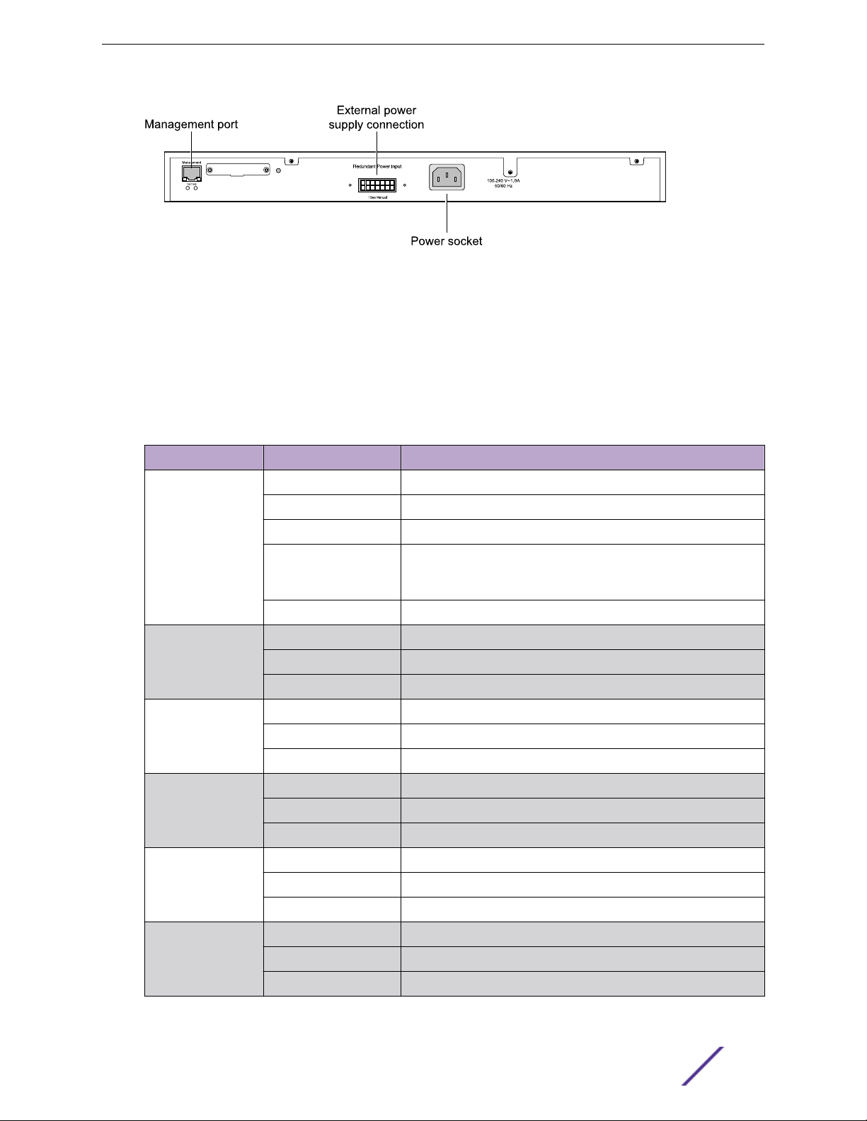
Figure 6: Summit X150-48t Switch Rear Panel
Summit X150 Series Switch LEDs
The following sections describe the meanings of the LEDs on Summit X150 switches.
LEDs on the Summit X150 Series Switches
Table 3: Front Panel
Label or Type Color/State Meaning
Summit Switches
MGMT Blinking green (fast) Power-on self-test (POST) in progress.
Steady green POST passed. System is booting image.
Blinking green (slow) Normal operation.
Blinking amber Switch diagnostics are running.
or
System is disabled. POST failed or system overheated.
O No external power attached.
FAN Steady green Normal operation.
Blinking amber Fan failure. Switch will continue to operate unless it overheats.
O No power.
PSU-I
(Internal power
supply)
PSU-E
(External power
supply)
Port number
1 – 24 or 1 – 48
Steady green Normal operation.
Blinking amber Failure.
O No power.
Steady green Normal operation.
Blinking amber Failure.
O No external power attached.
Steady green Link is OK.
Blinking green Port is transmitting packets.
O Link is not present, or port is disabled.
Port number
25, 26 or 49, 50
(Shared ports)
Summit Family Hardware Installation Guide 17
Steady green Link is OK.
Blinking green Activity.
O Link is not present, or port is disabled.
Page 18
Summit Switches
Table 4: Additional Port LED Meanings for PoE Switch: Summit X150-24p
Label or Type Color/State Meaning
All front-panel ports Steady green Link OK; port is not powered.
Steady amber Link is OK; port is powered; no trac.
Blinking green Link is OK and transmitting packets; port is not powered.
Blinking amber Link is OK and transmitting packets; port is powered.
Slow blinking amber No link, or disabled port; port is powered.
Alternating amber and
green
O Port is not powered, has no link, or is disabled.
Port has a power fault.
Table 5: Rear Panel
Label or Type Color/State Meaning
Management Port Right LED:
Steady green
Left LED:
Blinking green
Both LEDs o Link is not present.
Link is OK.
Activity.
Summit X250e Series Switches
The Summit X250e series switches provide 24 or 48 Ethernet ports that deliver high-density fast
Ethernet connectivity using fixed 10/100/1000BASE-T ports or installable small form pluggable (SFP)
optical modules.
Fixed-port models are available either with or without PoE. Each Summit X250e series switch has two
combination ports that provide 10/100/1000 BASE-T or SFP connectivity for 2 Gbps of copper or fiber
connectivity. A serial console port on the front panel allows you to connect a terminal and perform local
management. An Ethernet management port can be used to connect the system to a parallel
management network for administration. Alternatively, you can use an Ethernet cable to connect this
port directly to a laptop to view and locally manage the switch configurations.
On the back of the switch, two high-speed stacking ports allow you to combine multiple units into a
single SummitStack management entity. The rear panel also provides an AC or DC power input socket
and a redundant power connector. (See specific switch descriptions for more information about the
power options.) The switch automatically adjusts to the supply voltage. The redundant power
connector allows you to connect the switch to the EPS-160, EPS-500, or EPS-150DC external power
supply. When a compatible external power supply is used with the Summit X250e series switch, the
internal and external power supplies are fully fault tolerant and load-sharing. If one power supply fails,
the other power supply will provide sucient power to operate the switch.
The Summit X250e series switches include the following models:
Summit X250e-24t Switch Ports and Slots on page 19
•
Summit X250e-24t-TAA switch
•
Summit Family Hardware Installation Guide 18
Page 19

Summit X250e-24tDC Switch Ports and Slots on page 20
•
Summit X250e-24tDC-TAA switch
•
Summit X250e-24x Switch Ports and Slots on page 21
•
Summit X250e-24x-TAA switch
•
Summit X250e-24xDC Switch Ports and Slots on page 22
•
Summit X250e-24xDC-TAA switch
•
Summit X250e-24p Switch Ports and Slots on page 24
•
Summit X250e-24p-TAA switch
•
Summit X250e-48t Switch Ports and Slots on page 25
•
Summit X250e-48t-TAA switch
•
Summit X250e-48tDC Switch Ports and Slots on page 26
•
Summit X250e-48tDC-TAA switch
•
Summit X250e-48p Switch Ports and Slots on page 27
•
Summit X250e-48p-TAA switch
•
Note
In the descriptions that follow, references to a Summit X250e series model number also apply
to the equivalent TAA-compliant switch version.
Summit Switches
Summit X250e series switches require an ExtremeXOS version of at least 12.0.1.11 but not greater than
15.3.x.
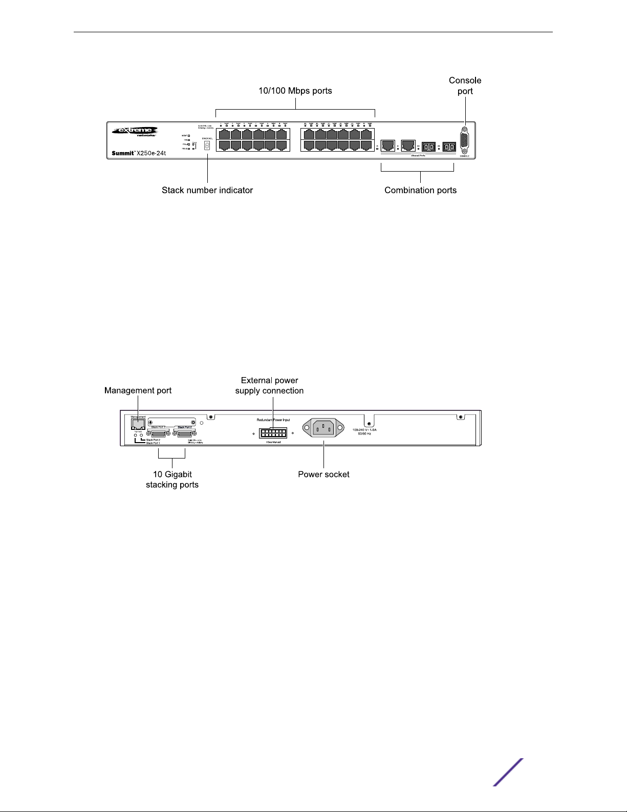
Summit X250e-24t Switch Ports and Slots
The front panel of the Summit X250e-24t switch includes:
Twenty-four fixed autosensing 10/100BASE-T ports (ports 1–24) that provide 2.4 Gbps of high-
•
density copper connectivity.
Two combination ports (ports 25–26) using RJ45 connectors and SFPs to provide 2 Gbps of copper
•
or fiber connectivity.
For more information about combination ports, see Combination Ports and Failover on page 12.
For information about SFPs, see the Extreme Networks Pluggable Transceivers Installation Guide.
LEDs to indicate port status and switch operating conditions.
•
For a description of the LEDs and their operation, see Summit X250e Series Switch LEDs on page
29.
Stack number indicator showing the position of this switch in a stacked configuration.
•
Serial console port used to connect a terminal and perform local management.
•
Summit Family Hardware Installation Guide 19
Page 20
Summit Switches
Figure 7: Summit X250e-24t Switch Front Panel
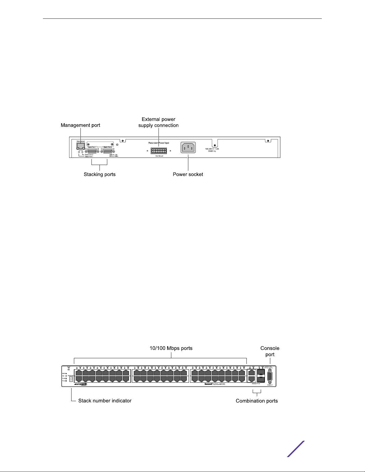
The rear panel of the Summit X250e-24t switch (shown in Figure 8 on page 20) includes:
Ethernet management port with associated LEDs.
•
Two high-performance stacking ports with associated LEDs.
•
Redundant power input connector for optional connection to the EPS-160 External Power Module.
•
The connecting redundant power supply cable is shipped with the EPS-160 unit. See EPS-160
External Power Module (with EPS-T) on page 150 for more information.
AC power input socket.
•
The internal AC power supply operates from 100 VAC to 240 VAC.
Figure 8: Summit X250e-24t Switch Rear Panel
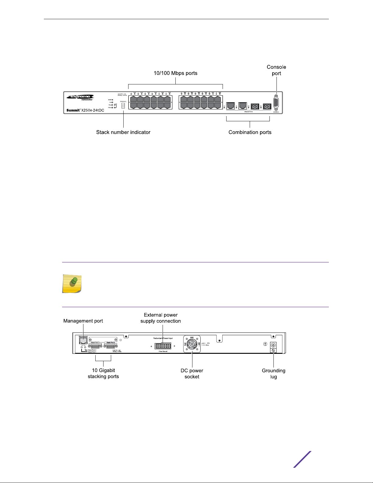
Summit X250e-24tDC Switch Ports and Slots
The front panel of the Summit X250e-24tDC switch includes:
Twenty-four fixed autosensing 10/100BASE-T ports (ports 1–24) that provide 2.4 Gbps of high-
•
density copper connectivity.
Two combination ports (ports 25–26) using RJ45 connectors and SFPs to provide 2 Gbps of copper
•
or fiber connectivity.
For more information about combination ports, see Combination Ports and Failover on page 12.
For information about SFPs, see the Extreme Networks Pluggable Transceivers Installation Guide.
LEDs to indicate port status and switch operating conditions.
•
For a description of the LEDs and their operation, see Summit X250e Series Switch LEDs on page
29.
Summit Family Hardware Installation Guide 20
Page 21
Summit Switches
Stack number indicator showing the position of this switch in a stacked configuration.
•
Serial console port used to connect a terminal and perform local management.
•
Figure 9: Summit X250e-24tDC Switch Front Panel
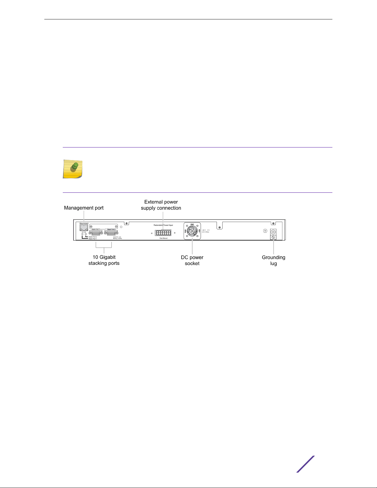
The rear panel of the Summit X250e-24tDC switch (shown in Figure 10 on page 21) includes:
Ethernet management port with associated LEDs.
•
Two high-performance stacking ports with associated LEDs.
•
Redundant power input connector for optional connection to the EPS-150DC External Power Module
•
(Model No. 10909).
The connecting redundant power supply cable is shipped with the EPS-150DC unit. See EPS-150DC
External Power Module (with EPS-T2) on page 149 for more information.
DC power input socket.
•
The internal power supply operates from -36 VDC to -72 VDC.
Grounding lug.
•
Note
For centralized DC power connection, this product is intended to be installed in a restricted
access location (such as a dedicated equipment room, equipment closet, or central oce) in
accordance with Articles 110-16, 110-17, and 110-18 of the National Electric Code, ANSI/NFPA
70.
Figure 10: Summit X250e-24tDC Switch Rear Panel
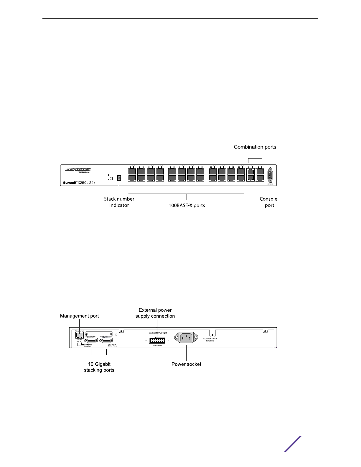
Summit X250e-24x Switch Ports and Slots
The front panel of the Summit X250e-24x switch includes:
Summit Family Hardware Installation Guide 21
Page 22
Summit Switches
Twenty-four 100BASE-FX ports (ports 1–24) that provide 2.4 Gbps of high-density fiber connectivity.
•
Two combination ports (ports 25–26) using RJ45 connectors and SFPs to provide 2 Gbps of copper
•
or fiber connectivity.
For more information about combination ports, see Combination Ports and Failover on page 12.
For information about SFPs, see the Extreme Networks Pluggable Transceivers Installation Guide.
LEDs to indicate port status and switch operating conditions.
•
For a description of the LEDs and their operation, see Summit X250e Series Switch LEDs on page
29.
Stack number indicator showing the position of this switch in a stacked configuration.
•
Serial console port used to connect a terminal and perform local management.
•
Figure 11: Summit X250e-24x Switch Front Panel
The rear panel of the Summit X250e-24x switch (shown in Figure 12 on page 22) includes:
Ethernet management port with associated LEDs.
•
Two high-performance stacking ports with associated LEDs.
•
Redundant power input connector for use with the EPS-160 External Power Module.
•
The connecting redundant power supply cable is shipped with the EPS-160 unit. See EPS-160
External Power Module (with EPS-T) on page 150 for more information.
AC power input socket.
•
The internal AC power supply operates from 100 VAC to 240 VAC.
Figure 12: Summit X250e-24x Switch Rear Panel
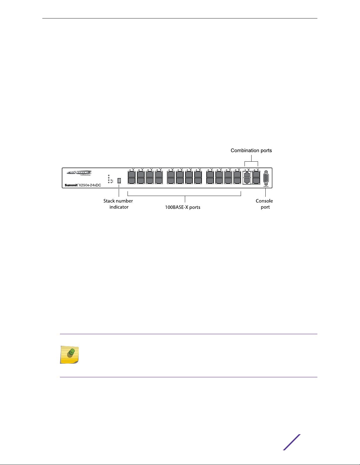
Summit X250e-24xDC Switch Ports and Slots
The front panel of the Summit X250e-24xDC switch includes:
Summit Family Hardware Installation Guide 22
Page 23
Summit Switches
Twenty-four 100BASE-FX ports (ports 1–24) that provide 2.4 Gbps of high-density fiber connectivity.
•
Two combination ports (ports 25–26) using RJ45 connectors and SFPs to provide 2 Gbps of copper
•
or fiber connectivity.
For more information about combination ports, see Combination Ports and Failover on page 12.
For information about SFPs, see the Extreme Networks Pluggable Transceivers Installation Guide.
LEDs to indicate port status and switch operating conditions.
•
For a description of the LEDs and their operation, see Summit X250e Series Switch LEDs on page
29.
Stack number indicator showing the position of this switch in a stacked configuration.
•
Serial console port used to connect a terminal and perform local management.
•
Figure 13: Summit X250e-24xDC Switch Front Panel
The rear panel of the Summit X250e-24xDC switch (Figure 14 on page 24) includes:
Ethernet management port with associated LEDs.
•
Two high-performance stacking ports with associated LEDs.
•
Redundant power input connector for use with the EPS-150DC External Power Module (Model No.
•
10909).
The connecting redundant power supply cable is shipped with the EPS-150DC unit. See EPS-150DC
External Power Module (with EPS-T2) on page 149 for more information.
DC power input socket.
•
The internal power supply operates from -36 VDC to -72 V DC.
Grounding lug.
•
Note
For centralized DC power connection, this product is intended to be installed in a restricted
access location (such as a dedicated equipment room, equipment closet, or central oce) in
accordance with Articles 110-16, 110-17, and 110-18 of the National Electric Code, ANSI/NFPA
70.
Summit Family Hardware Installation Guide 23
Page 24
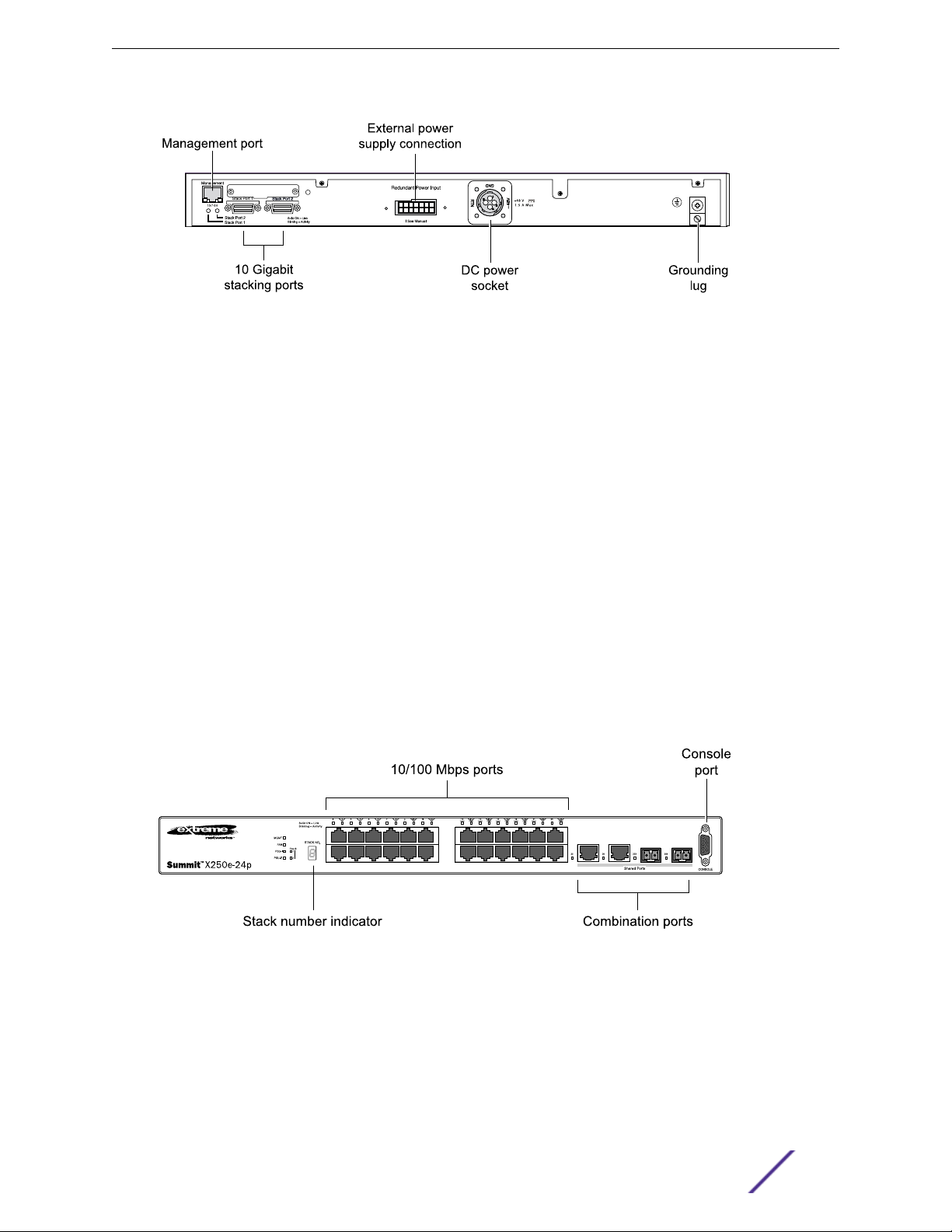
Figure 14: Summit X250e-24xDC Switch Rear Panel
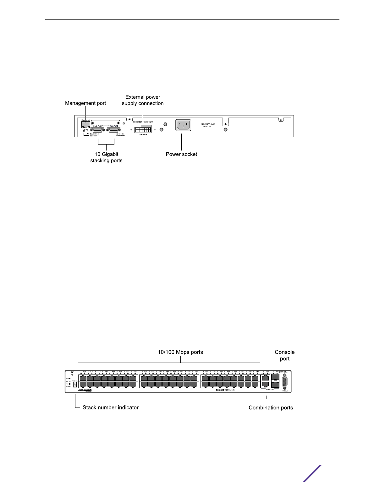
Summit X250e-24p Switch Ports and Slots
The front panel of the Summit X250e-24p switch includes:
Twenty-four fixed autosensing 10/100BASE-T PoE ports (ports 1–24). In addition to 2.4 Gbps of
•
high-density copper connectivity, these ports also provide a full 15.4 Watts of PoE per port.
Two combination ports (ports 25–26) using RJ45 connectors and SFPs to provide 2 Gbps of copper
•
or fiber connectivity.
Summit Switches
For more information about combination ports, see Combination Ports and Failover on page 12.
For information about SFPs, see the Extreme Networks Pluggable Transceivers Installation Guide.
LEDs to indicate port status and switch operating conditions.
•
For a description of the LEDs and their operation, see Summit X250e Series Switch LEDs on page
29.
Stack number indicator showing the position of this switch in a stacked configuration.
•
Serial console port used to connect a terminal and perform local management.
•
Figure 15: Summit X250e-24p Switch Front Panel
The rear panel of the Summit X250e-24p switch (shown in Figure 16 on page 25) includes:
Ethernet management port with associated LEDs.
•
Two high-performance stacking ports with associated LEDs.
•
Redundant power input connector for use with the EPS-500 External Power Supply (Model No.
•
10911) with full PoE power support.
Summit Family Hardware Installation Guide 24
Page 25
Summit Switches
The connecting redundant power supply cable is shipped with the EPS-500 unit. See EPS-500
External Power Supply Unit on page 151 for more information.
AC power input socket.
•
The internal AC power supply operates from 100 VAC to 240 VAC.
Figure 16: Summit X250e-24p Switch Rear Panel
Summit X250e-48t Switch Ports and Slots
The front panel of the Summit X250e-48t switch includes:
Forty-eight fixed autosensing 10/100BASE-T ports (ports 1–48) that provide 4.8 Gbps of high-
•
density copper connectivity.
Two combination ports (ports 49–50) using RJ45 connectors and SFPs to provide 2 Gbps of copper
•
or fiber connectivity.
For more information about combination ports, see Combination Ports and Failover on page 12.
For information about SFPs, see the Extreme Networks Pluggable Transceivers Installation Guide.
LEDs to indicate port status and switch operating conditions.
•
For a description of the LEDs and their operation, see Summit X250e Series Switch LEDs on page
29.
Stack number indicator showing the position of this switch in a stacked configuration.
•
Serial console port used to connect a terminal and perform local management.
•
Figure 17: Summit X250e-48t Switch Front Panel
The rear panel of the Summit X250e-48t switch (Figure 18 on page 26) includes:
Summit Family Hardware Installation Guide 25
Page 26
Summit Switches
Management port with associated LEDs.
•
Two high-performance stacking ports with associated LEDs.
•
Redundant power input connector for optional connection to the EPS-160 External Power Module.
•
The connecting redundant power supply cable is shipped with the EPS-160 unit. See EPS-160
External Power Module (with EPS-T) on page 150 for more information.
AC power input socket.
•
The internal AC power supply operates from 100 VAC to 240 VAC.
Figure 18: Summit X250e-48t Switch Rear Panel
Summit X250e-48tDC Switch Ports and Slots
The front panel of the Summit X250e-48tDC switch includes:
Forty-eight fixed autosensing 10/100BASE-T ports (ports 1–48) that provide 4.8 Gbps of high-
•
density copper connectivity.
Two combination ports (ports 49–50) using RJ45 connectors and SFPs to provide 2 Gbps of copper
•
or fiber connectivity.
For more information about combination ports, see Combination Ports and Failover on page 12.
For information about SFPs, see the Extreme Networks Pluggable Transceivers Installation Guide.
LEDs to indicate port status and switch operating conditions
•
For a description of the LEDs and their operation, see Summit X250e Series Switch LEDs on page
29.
Stack number indicator showing the position of this switch in a stacked configuration.
•
Serial console port used to connect a terminal and perform local management.
•
Figure 19: Summit X250e-48tDC Switch Front Panel
Summit Family Hardware Installation Guide 26
Page 27
Summit Switches
The rear panel of the Summit X250e-48tDC switch (shown in Figure 20 on page 27) includes:
Management port with associated LEDs.
•
Two high-performance stacking ports with associated LEDs.
•
Redundant power input connector for use with the EPS-150DC External Power Module (Model No.
•
10909).
The connecting redundant power supply cable is shipped with the EPS-150DC unit. See EPS-150DC
External Power Module (with EPS-T2) on page 149 for more information.
DC power input socket.
•
The internal power supply operates from -36 VDC to -72 VDC.
Grounding lug.
•
Note
For centralized DC power connection, this product is intended to be installed in a restricted
access location (such as a dedicated equipment room, equipment closet, or central oce) in
accordance with Articles 110-16, 110-17, and 110-18 of the National Electric Code, ANSI/NFPA
70.
Figure 20: Summit X250e-48tDC Switch Rear Panel
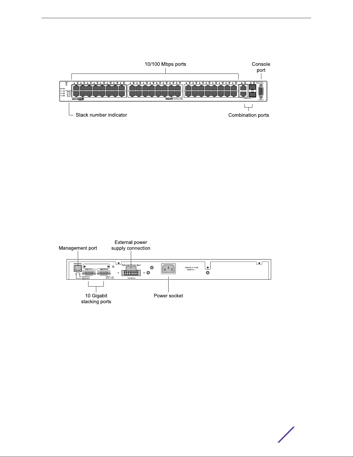
Summit X250e-48p Switch Ports and Slots
The front panel of the Summit X250e-48p switch includes:
Forty-eight fixed autosensing 10/100BASE-T PoE ports (ports 1–48). In addition to 4.8 Gbps of high-
•
density copper connectivity, these ports provide a full 15.4 Watts of PoE per port when used with the
EPS-600LS External Power Module.
Two combination ports (ports 49–50) using RJ45 connectors and SFPs to provide 2 Gbps of copper
•
or fiber connectivity.
For more information about combination ports, see Combination Ports and Failover on page 12.
For information about SFPs, see the Extreme Networks Pluggable Transceivers Installation Guide.
LEDs to indicate port status and switch operating conditions.
•
For a description of the LEDs and their operation, see Summit X250e Series Switch LEDs on page
29.
Summit Family Hardware Installation Guide 27
Page 28
Summit Switches
Stack number indicator showing the position of this switch in a stacked configuration.
•
Serial console port used to connect a terminal and perform local management.
•
Figure 21: Summit X250e-48p Switch Front Panel
The rear panel of the Summit X250e-48p switch (shown in Figure 22 on page 28) includes:
Ethernet management port with associated LEDs.
•
Two high-performance stacking ports with associated LEDs.
•
Redundant power input connector for use with one or more EPS-600LS External Power Modules
•
(Model No. 10913) installed in an EPS-C chassis (Model No. 10912).
The connecting redundant power supply cable is shipped with the EPS-C chassis. The PoE capability
of the Summit X250e-48p switch varies depending on the number of external power modules in use.
For more information, see EPS-600LS External Power Module on page 152.
AC power input socket.
•
The internal AC power supply operates from 100 VAC to 240 VAC.
Figure 22: Summit X250e-48p Switch Rear Panel
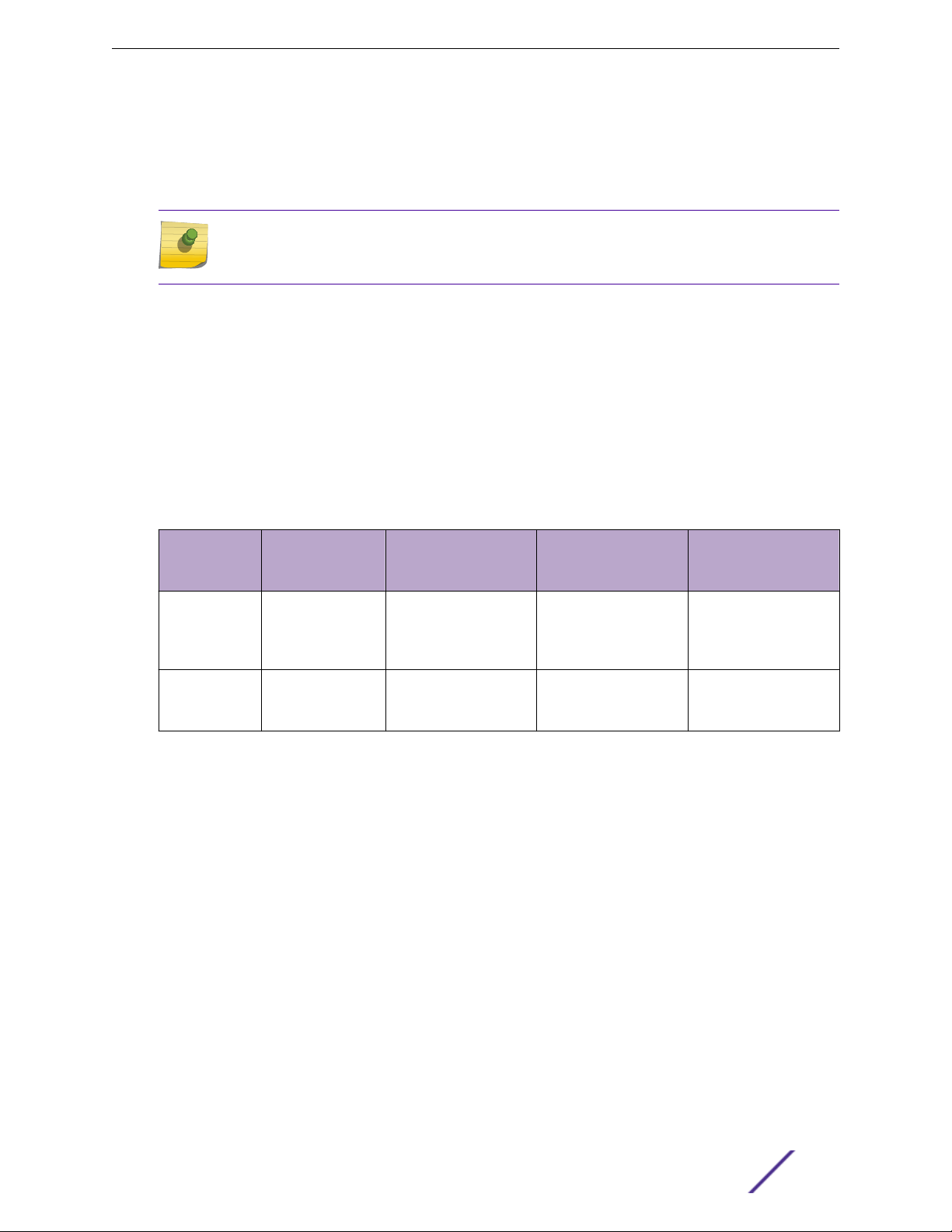
Summit X250e-48p Power Supplies
The Summit X250e-48p switch is powered by both an internal power supply and an optional external
redundant power supply system.
Internal Power Supply
The Summit X250e-48p internal power supply can provide 370 W of PoE power, as follows:
In a 24-port configuration, it provides 15.4 W to each port.
•
In a 48-port configuration or any combination of ports where total PoE power does not exceed 370
•
watts, it provides 7.7 W to each port.
Summit Family Hardware Installation Guide 28
Page 29
Summit Switches
If the total system demands exceed this power limit, you can specify one of the following:
Port priorities to identify which ports should be ranked higher when allocating power
•
Port disconnect precedence to specify the method of shutting o ports when not enough PoE
•
power is available
Note
For a detailed discussion of these concepts, see the Power over Ethernet section in the
ExtremeXOS 22.3 User Guide.
External Power Supplies
The EPS-600LS External Power Module provides optional redundant power for the Summit X250e-48p
switch.
Through the redundant power input connector on the rear panel, the switch can be powered by one,
two, or three external power modules installed in the EPS-C External Power Supply Chassis.
The PoE capability of the Summit X250e-48p varies depending on the number of external power
modules in use. The following table summarizes the PoE power behavior for the Summit X250e-48p
switch based on the number of power supply modules in use.
Internal Power
Supply Status
Internal power
supply:
Power on
Internal power
supply:
Power Failure
EPS-600LS (1x) EPS-600LS (2x) EPS-600LS (3x) External Power Supply/
Chassis Failed/
Disconnected
370 W of
redundant power
370 W of external
power only
740 W of external
power only; internal
power supply disabled
740 W of external
power only
740 W of external
power only with 2:1
redundancy; internal
power supply disabled
740 W of external
power only with 2:1
redundancy
370 W of internal
power only
No PoE power
For specifications and installation instructions for the external power module, see EPS-600LS External
Power Module on page 152.
Summit X250e Series Switch LEDs
The following sections describe the meanings of the LEDs on Summit X250e switches.
Summit Family Hardware Installation Guide 29
Page 30
LEDs on the Summit X250e Series Switches
Table 6: Front Panel
Label or Type Color/State Meaning
MGMT Blinking green (fast) Power-on self-test (POST) in progress
Steady green POST passed. System is booting image.
Blinking green (slow) Normal operation.
Blinking amber Switch diagnostics are running.
or
System is disabled. POST failed or system overheated.
O No external power attached
FAN Steady green Normal operation
Blinking amber Fan failure. Switch will continue to operate unless it overheats.
O No power
Summit Switches
PSU-I
(Internal power
supply)
PSU-E
(External power
supply)
Port number
1 – 24 or 1 – 48
Port number
25, 26 or 49, 50
(Shared ports)
Stack 1, Stack 2 Steady green Link OK on the indicated stacking port.
Stack Number
Indicator
Steady green Normal operation
Blinking amber Failure
O No power
Steady green Normal operation
Blinking amber Failure
O No external power attached
Steady green Link is OK.
Blinking green Port is transmitting packets.
O Link is not present, or port is disabled.
Steady green Link is OK.
Blinking green Port is transmitting packets.
O Link is not present, or port is disabled.
Blinking green Activity on the indicated stacking port.
O This switch is not in stacking mode.
Top half of number blinking This switch is the stack master.
Lower half of number
blinking
This switch is the stack backup.
Number lights steadily This switch is a standby switch (neither the master nor the
backup).
Summit Family Hardware Installation Guide 30
Page 31

Summit Switches
Table 7: Additional Port LED Meanings for PoE Switches: Summit X250e-24p &
Summit X250e-48p
Label or Type Color/State Meaning
All front-panel
ports
Steady green Link OK. port not powered.
Steady amber Link OK, port is powered, no trac
Blinking green Link OK, transmitting packets, port not powered.
Blinking amber Link OK, transmitting packets, port is powered.
Slow blinking amber No link or disabled port, port is powered
Alternating amber and
green
O Port is not powered, has no link, or is disabled.
Port has a power fault.
Table 8: Rear Panel
Label or Type Color/State Meaning
Management
Port
Stack Port 1,
Stack Port 2
Right LED: Steady green Link OK
Left LED: Blinking green Activity
Both LEDs o Link is not present.
Steady green Link OK
Blinking green Activity
O No link
Summit X350 Series Switches
The Summit X350 series switches provide 24 or 48 Ethernet ports that deliver high-density fast
Ethernet connectivity using fixed 10/100/1000BASE-T ports.
Each Summit X350 series switch has four combination ports that provide 10/100/1000 BASE-T or SFP
connectivity for 2 Gbps of copper or fiber connectivity. A serial console port on the front panel allows
you to connect a terminal and perform local management. An Ethernet management port can be used
to connect the system to a parallel management network for administration. Alternatively, you can use
an Ethernet cable to connect this port directly to a laptop to view and locally manage the switch
configurations.
The rear panel of the switch has an option slot to accommodate one of the following Summit port
option cards:
Summit XGM2-2xf option card, which allows you to add one or two 10-gigabit XFP modules.
•
Summit XGM2-2xn option card, which allows you to add one or two 10-gigabit XFP modules.
•
Summit XGM2-2bt option card, which allows you to add one or two fixed 10GBASE-T ports.
•
Summit XGM2-2sf option card, which allows you to add one or two 10-gigabit SFP+ modules.
•
For option card installation instructions, see Installing Port Option Cards and VIMs on page 354.
Summit Family Hardware Installation Guide 31
Page 32

Summit Switches
Power connectors on the rear panel of the switch include an AC power input socket and a redundant
power connector. The internal AC power supply operates from 100 VAC to 240 VAC. The switch
automatically adjusts to the supply voltage. The redundant power connector allows you to connect the
switch to the EPS-500 external power supply. When a compatible external power supply is used with
the Summit X350 series switch, the internal and external power supplies are fully fault tolerant and
load-sharing. If one power supply fails, the other power supply provides sucient power to operate the
switch.
The Summit X350 series switches include the following models:
Summit X350-24t Switch Ports and Slots on page 32
•
Summit X350-24t-TAA switch
•
Summit X350-48t Switch Ports and Slots on page 33
•
Summit X350-48t-TAA switch
•
Note
In the descriptions that follow, references to a Summit X350 series model number also apply
to the equivalent TAA-compliant switch version.
Summit X350 series switches require an ExtremeXOS version of at least 12.0.3.16 but not greater than
15.3.x.
Summit X350-24t Switch Ports and Slots
The front panel of the Summit X350-24t switch includes:
Twenty fixed autosensing 10/100/1000BASE-T ports (ports 1–20) that provide 20 Gbps of high-
•
density copper connectivity
Four combination ports (ports 21-24) using RJ45 connectors and SFPs to provide 4 Gbps of copper
•
or fiber connectivity
For more information about combination ports, see Combination Ports and Failover on page 12.
For information about SFPS, see the Extreme Networks Pluggable Transceivers Installation Guide.
LEDs to indicate port status and switch operating conditions
•
For a description of the LEDs and their operation, see Summit X350 Series Switch LEDs on page
35.
Serial console port used to connect a terminal and perform local management.
•
Figure 23: Summit X350-24t Switch Front Panel
Summit Family Hardware Installation Guide 32
Page 33

Summit Switches
The rear panel of the Summit X350-24t switch (as shown in Figure 24 on page 33) includes a slot for
one of the Summit option cards listed in the following table. These port option cards allow you to add
one or two high-speed uplink ports to the switch.
Table 9: Port Option Cards for Summit X350 Series Switches
Option Card Model Type of Added Ports For More Information, see . . .
XGM2-2xn option card 10-gigabit XENPAK modules Summit XGM2-2xn Option Card on page 167
XGM2-2xf option card 10-gigabit XFP modules Summit XGM2-2xf Option Card on page 168
XGM2-2sf option card 10-gigabit SFP+ modules Summit XGM2-2sf Option Card on page 169
XGM2-2bt option card Fixed 10GBASE-T copper Summit XGM2-2bt Option Card on page 170
The rear panel of the Summit X350-24t switch also includes:
Management port with associated LEDs.
•
Redundant power input connector for optional connection to the EPS-500 External Power Module
•
(Model No. 10907).
The connecting redundant power supply cable is shipped with the EPS-500 unit. See EPS-500
External Power Supply Unit on page 151 for more information.
AC power input socket.
•
The internal power supply operates from 100 VAC to 240 VAC.
Figure 24: Summit X350-24t Switch Rear Panel
Summit X350-48t Switch Ports and Slots
The front panel of the Summit X350-48t switch includes:
Forty-four fixed autosensing 10/100/1000 BASE-T ports (ports 1–44) that provide 44 Gbps of high-
•
density copper connectivity.
Four combination ports (ports 45–48) using RJ45 connectors and SFPs to provide 4 Gbps of copper
•
or fiber connectivity. For more information about combination ports, see Combination Ports and
Failover on page 12.
For information about SFPs, see the Extreme Networks Pluggable Transceivers Installation Guide.
LEDs to indicate port status and switch operating conditions
•
Summit Family Hardware Installation Guide 33
Page 34

Summit Switches
For a description of the LEDs and their operation, see Summit X350 Series Switch LEDs on page
35.
Serial console port used to connect a terminal and perform local management.
•
Figure 25: Summit X350-48t Switch Front Panel
The rear panel of the Summit X350-48t switch includes a slot for one of the Summit option cards listed
in the following table. These port option cards allow you to add one or two high-speed uplink ports to
the switch.
Table 10: Port Option Cards for Summit X350 Series Switches
Option Card Model Type of Added Ports For More Information, see . . .
XGM2-2xn option card 10-gigabit XENPAK modules Summit XGM2-2xn Option Card on page 167
XGM2-2xf option card 10-gigabit XFP modules Summit XGM2-2xf Option Card on page 168
XGM2-2sf option card 10-gigabit SFP+ modules Summit XGM2-2sf Option Card on page 169
XGM2-2bt option card Fixed 10GBASE-T copper Summit XGM2-2bt Option Card on page 170
The rear panel of the Summit X350-48t switch also includes:
Management port with associated LEDs.
•
Redundant power input connector for optional connection to the EPS-500 External Power Supply
•
Unit (Model No. 10911).
The connecting redundant power supply cable is shipped with the EPS-500 power supply. See
EPS-500 External Power Supply Unit on page 151 for more information.
AC power input socket.
•
The internal power supply operates from 100 VAC to 240 VAC.
Summit Family Hardware Installation Guide 34
Page 35

Figure 26: Summit X350-48t Switch Rear Panel
Summit X350 Series Switch LEDs
The following sections describe the meanings of the LEDs on Summit X350 switches.
Summit Switches
Table 11: Front Panel
Label or Type Color/State Meaning
MGMT Blinking green (fast) Power-on self-test (POST) in progress.
Steady green POST passed. System is booting image.
Blinking green (slow) Normal operation
Blinking amber Switch diagnostics are running.
or
System is disabled. POST failed or system overheated.
FAN Steady green Normal operation
Blinking amber Failure
O No power
PSU-I (Internal power supply) Steady green Normal operation
Blinking amber Failure
O No power
PSU-E (External power
supply)
Steady green Normal operation
Blinking amber Failure
O No external power attached.
Summit Family Hardware Installation Guide 35
Page 36

Table 12: Front-panel Port LEDs
Label or Type Color/State Meaning
Summit Switches
Ethernet Ports
1 – 24 or 1 – 48 (21 – 24 and 45
– 48 are shared ports)
Steady green Link OK
Blinking green Activity
O Link is not present.
or
Port is disabled.
Table 13: Rear Panel
Label or Type Color/State Meaning
Management Port Steady green Link OK
Blinking green Activity
O Link is not present.
SFP+ 10G Port
(on installed option card)
XFP 10G Port
(on installed option card)
Steady green Link OK
Blinking green Activity
O Link down
Steady green Link OK
Blinking green Activity
O Link down
Summit X430 Series Switches
The Summit X430 series switches provide 8, 24, or 48 Ethernet ports that deliver high-density fast
Ethernet or Gigabit Ethernet connectivity using fixed 10/100/1000Base-T copper or POE+ ports, plus
four 100/1000Base-X fiber ports via SFP modules on some models.
For all models, a serial console port on the front panel allows you to connect a terminal and perform
local management. An Ethernet management port can be used to connect the system to a parallel
management network for administration. Alternatively, you can use an Ethernet cable to connect this
port directly to a laptop to view and locally manage the switch configurations. The rear panel provides
an AC power input socket.
The Summit X430 series switches include the following models:
Summit X430-8p switch
•
Summit X430-24t switch
•
Summit X430-24p switch
•
Summit X430-48t switch
•
Summit X430-24t and X430-48t switches require an ExtremeXOS version of at least 16.3.2 but not
greater than 16.x.
Summit X430-8p and X430-24p switches require an ExtremeXOS version of at least 15.5.2 but not
greater than 16.x.
Summit Family Hardware Installation Guide 36
Page 37

Summit X430-8p Switch Ports and Slots
The front panel of the Summit X430-8p switch includes:
Eight fixed autosensing 10/100/1000BASE-T ports (ports 1–8) that provide 8 Gbps of high-density
•
copper connectivity. In addition, all of these ports (ports 1-8) also support the POE protocol
IEEE802.af and POE+ protocol IEEE 802.at standard. Using the POE protocol, the switch can provide
15.4 Watts of power on a single port up to a total power budget of 60 Watts. Using the POE+
protocol, the switch can provide 30 Watts of power on a single port up to a total power budget of
60 Watts.
Note
Up to 90 watts of PoE power can be configured on the switch if it is used standalone and
not in a rack.
Two unpopulated 1000BASE-X SFP ports (ports 9–10) that provide 2 Gbps of fiber connectivity.
•
Note
All the eight 10/100/1000BASE-T ports and all of the 1000BASE-X SFP ports can be used
simultaneously.
Summit Switches
For information about SFPs, see the Extreme Networks Pluggable Interface Modules Installation
Guide.
Ethernet management port.
•
Serial console port implemented as an RJ45 connector, used to connect a terminal and perform local
•
management.
LEDs to indicate port status and switch operating conditions
•
For a description of the LEDs and their operation, see Summit X430 Series Switch LEDs on page
42.
Note
If you are desktop mounting a Summit X430-8p switches you must use the four rubber
pads to maintain sucient airflow around the unit See Installing Summit Switches in
Desktop or Free-Standing Mode on page 280 for installation instructions.
Note
If you are rack mounting Summit X430-8p switches, you must use special "keep out" rack
mounting hardware. Rack mounting hardware must be ordered separately and you must
reserve at least 2 RU of space for the unit. For installation instructions, see Installing a
Summit X430-8p or X440-8t Switch in a Rack on page 265.
Summit Family Hardware Installation Guide 37
Page 38

4
2
1
3
Figure 27: Summit X430-8p Switch Front Panel
100-2 40 V~1. 75A
50 60 Hz
1
-
1 = Ethernet management port 3 = SFP ports
2 = 10/100/1000BASE-T POE+ ports 4 = Console port
The rear panel of the Summit X430-8p switch includes:
AC power input socket
•
Summit Switches
The internal AC power supply operates from 100 VAC to 240 VAC.
Figure 28: Summit X430-8p Switch Rear Panel
1 = AC power input connector
Summit X430-24t Switch Ports and Slots
The front panel of the Summit X430-24t switch includes:
Twenty-four fixed autosensing 10/100/1000BASE-T ports (ports 1–24) that provide 24 Gbps of high-
•
density copper connectivity.
Four unpopulated 1000BASE-X SFP ports (ports 25–28) that provide 4 Gbps of fiber connectivity.
•
Note
All of the 10/100/1000BASE-T ports and four 1000BASE-X SFP ports can be used
simultaneously.
For information about SFPs, see the Extreme Networks Pluggable Interface Modules Installation
Guide.
Ethernet management port.
•
Summit Family Hardware Installation Guide 38
Page 39

X430-2 4t
25
26
27
28
25 26
27 28
FAN
MGMT
4
321
1
0.75A
Summit Switches
Serial console port implemented as an RJ45 connector, used to connect a terminal and perform local
•
management.
LEDs to indicate port status and switch operating conditions.
•
For a description of the LEDs and their operation, see Summit X430 Series Switch LEDs on page
42.
Figure 29: Summit X430-24t Switch Front Panel
1 = Ethernet management port 3 = SFP ports
2 = 10/100/1000BASE-T ports 4 = Console port
The rear panel of the Summit X430-24t switch (shown in Figure 30) includes:
AC power input socket
•
The internal AC power supply operates from 100 VAC to 240 VAC.
Figure 30: Summit X430-24t Switch Rear Panel
1 = AC power input connector
Summit X430-24p Switch Ports and Slots
The front panel of the Summit X430-24p switch includes:
Twenty-four fixed autosensing 10/100/1000BASE-T ports (ports 1–24) that provide 24 Gbps of high-
•
density copper connectivity. In addition, all of these ports (ports 1-24) also support the POE protocol
IEEE802.af and POE+ protocol IEEE 802.at standard. Using the POE protocol, the switch can provide
15.4 Watts of power on a single port up to a total power budget of 370 Watts. Using the POE+
Summit Family Hardware Installation Guide 39
Page 40

X430-24p
25
26
27
28
25 26
27 28
FAN
MGMT
4
321
1
5.75A
Summit Switches
protocol, the switch can provide 30 Watts of power on a single port up to a total power budget of
370 Watts.
Four unpopulated 1000BASE-X SFP ports (ports 25–28) that provide 4 Gbps of fiber connectivity.
•
Note
All the twenty-four 10/100/1000BASE-T ports and all four of the 1000BASE-X SFP ports
can be used simultaneously.
For information about SFPs, see the Extreme Networks Pluggable Interface Modules Installation
Guide.
Ethernet management port.
•
Serial console port implemented as an RJ45 connector, used to connect a terminal and perform local
•
management.
LEDs to indicate port status and switch operating conditions.
•
For a description of the LEDs and their operation, see Summit X430 Series Switch LEDs on page
42.
Figure 31: Summit X430-24p Switch Front Panel
1 = Ethernet management port
2 = 10/100/1000BASE-T POE+ ports 4 = Console port
3 = SFP ports
The rear panel of the Summit X430-24p switch (shown in Figure 32) includes:
AC power input socket
•
The internal AC power supply operates from 100 VAC to 240 VAC.
Figure 32: Summit X430-24p Switch Rear Panel
1 = AC power input connector
Summit Family Hardware Installation Guide 40
Page 41

Summit X430-48t Switch Ports and Slots
2
43
1
FAN
MGMT
X430-48t
52
51
50
49
525150
49
1
0.75A
The front panel of the Summit X430-48t switch includes:
Forty-eight fixed autosensing 10/100/1000BASE-T ports (ports 1–48) that provide 48 Gbps of high-
•
density copper connectivity.
Four 1000BASE-X SFP ports (ports 49–52) that provide 4 Gbps of fiber connectivity.
•
Note
All the forty-eight 10/100/1000BASE-T ports and all four of the 1000BASE-X SFP ports
can be used simultaneously.
For information about SFPs, see the Extreme Networks Pluggable Interface Modules Installation
Guide.
Ethernet management port.
•
Serial console port implemented as an RJ45 connector, used to connect a terminal and perform local
•
management.
LEDs to indicate port status and switch operating conditions.
•
Summit Switches
For a description of the LEDs and their operation, see Summit X430 Series Switch LEDs on page 42.
Figure 33: Summit X430-48t Switch Front Panel
1 = Ethernet management port
2 = Console port 4 = SFP ports
3 = 10/100/1000BASE-T ports
The rear panel of the Summit X430-48t switch (shown in Figure 34) includes:
AC power input socket.
•
The internal AC power supply operates from 100 VAC to 240 VAC.
Figure 34: Summit X430-48t Switch Rear Panel
Summit Family Hardware Installation Guide 41
1 = AC power input connector
Page 42

Summit X430 Series Switch LEDs
The following table describes the meanings of the LEDs on Summit X430 switches.
Table 14: X430 Front Panel LEDs
Label or Type Color/State Meaning
MGMT Blinking green Power-on self-test (POST) in progress.
Steady green POST passed. Normal operation.
Blinking amber System is disabled. POST failed or system overheated.
O No external power attached.
FAN Steady green Normal operation, fan is good.
Blinking amber Fan failure. Switch will continue to operate unless it overheats.
O No power
Summit Switches
PSU
(Internal power
supply)
Port number
1-8 or
1 – 24 or
1 – 48
Port number
9-10 or
25 – 28 or
49 – 52
(SFP ports)
Steady green Normal operation.
O No power is attached/Power failure.
Steady green Link is OK.
Blinking green Port is transmitting packets.
Solid Amber (POE only) POE delivering with Ethernet link OK.
Fast Blinking Amber
(POE only)
Slow Blinking Amber
(POE only)
O Link is not present, or port is disabled.
Steady green Link is OK.
Blinking green Port is transmitting packets.
O Link is not present, or port is disabled.
POE delivering and port is transmitting packets.
POE fault detected.
Summit X440 Series Switches
The Summit X440 series switches provide 8, 24, or 48 Ethernet ports that deliver high-density fast
Ethernet or Gigabit Ethernet connectivity using fixed 10/100/1000BASE-T or 100/1000 BASE-X ports.
Additional ports on various models include the following:
Summit Family Hardware Installation Guide 42
Page 43

Table 15: X440 Series Switches and Port Types
10/100/1000BASE-T
RJ45
X440-8t 8 4 (unpopulated)
X440-8p 8 4 (unpopulated)
10/100/1000BASE-T
POE+ RJ45
100/1000BASE-X
SFP
Summit Switches
10G BASE-X SFP+
X440-24t
X440-24tDC
X440-24p 24 (four are combo
X440-24x 4 (four are combo
X440-L2-24t 24 (four are combo
X440-24t-10G 24 4 (unpopulated
X440-24p-10G 24 (four are combo
X440-24x-10G 4 (combo ports) 24 (unpopulated)
X440-48t
X440-48tDC
X440-48p 48 (four are combo
X440-L2-48t 48 (four are combo
24 (four are combo
ports)
ports)
ports)
48 (four are combo
ports)
ports)
ports)
ports)
ports)
4 (unpopulated
combo ports)
4 (unpopulated
combo ports)
24 (unpopulated)
(four are combo
ports)
4 (unpopulated
combo ports)
combo ports)
4 (unpopulated
combo ports)
(four are combo
ports)
4 (unpopulated
combo ports)
4 (unpopulated
combo ports)
4 (unpopulated
combo ports)
2 (unpopulated)
2 (unpopulated)
2 (unpopulated)
X440-48t-10G 48 (two are combo
ports)
X440-48p-10G 48 (two are combo
ports)
2 (unpopulated
combo ports)
2 (unpopulated
combo ports)
2 (unpopulated)
2 (unpopulated)
For all models, a serial console port on the front panel allows you to connect a terminal and perform
local management. An Ethernet management port can be used to connect the system to a parallel
management network for administration. Alternatively, you can use an Ethernet cable to connect this
port directly to a laptop to view and locally manage the switch configurations.
Most models have two high-speed stacking ports that allow you to combine multiple units into a single
SummitStack management entity. On the 8-port models, the stacking ports are on the front panel. On
the 24 and 48 port 10-G models, the SFP+ 10G ports on the front panel can be used as alternate
stacking ports. On all other Summit X440 series switches (except the x440-L2-24t and x440-L2-48t
which do not have stacking capability), the stacking ports are on the back panel. Stacking port locations
are listed in the following table.
Summit Family Hardware Installation Guide 43
Page 44

X440 Switch Type Stacking Port type Port Location
8p and 8t High-speed stacking port Front panel
Summit Switches
24p, 24t, 24tDC, 24x, 48p, 48t,
48tDC
24p-10G, 24t-10G, 24x-10G 48p-10G,
48t-10G
Note
The X440-L2-24t and the X440-L2-48t do not have stacking capability.
The rear panel provides an AC power input socket or DC input connector; 24-port and 48-port switch
models also include a redundant power connector. The switch automatically adjusts to the supply
voltage. The redundant power connector allows you to connect the switch to the EPS-C2 external
power system. When a compatible external power supply is used with the Summit X440 series switch,
the internal and external power supplies are fully fault tolerant. If one power supply fails, the other
power supply will provide sucient power to operate the switch.
Most Summit switches have fans that can change speeds depending upon operating conditions. See
Summit X440 Series Switches Technical Specifications on page 444 for specifications.
The Summit X440 series switches include the following models:
Summit X440-8t Switch Ports and Slots on page 44
•
Summit X440-8p Switch Ports and Slots on page 46
•
Summit X440-24t Switch Ports and Slots on page 47
•
Summit X440-24tDC Switch Ports and Slots on page 48
•
Summit X440-24t-10G Switch Ports and Slots on page 49
•
Summit X440-L2-24t Switch Ports and Slots on page 51
•
Summit X440-24x Switch Ports and Slots on page 52
•
Summit X440-24x-10G Switch Ports and Slots on page 53
•
Summit X440-24p Switch Ports and Slots on page 54
•
Summit X440-24p-10G Switch Ports and Slots on page 56
•
Summit X440-48t Switch Ports and Slots on page 57
•
Summit X440-48tDC Switch Ports and Slots on page 58
•
Summit X440-48t-10G Switch Ports and Slots on page 59
•
Summit X440-L2-48t Switch Ports and Slots on page 60
•
Summit X440-48p Switch Ports and Slots on page 62
•
Summit X440-48p-10G Switch Ports and Slots on page 63
•
High-speed stacking port Rear panel
SFP+ Front panel
The minimum required ExtremeXOS version for Summit X440 series switches varies by model. (See the
Extreme Hardware/Software Compatibility and Recommendation Matrices for details.) The ExtremeXOS
version cannot be greater than 16.x.
Summit X440-8t Switch Ports and Slots
The front panel of the Summit X440-8t switch includes:
Summit Family Hardware Installation Guide 44
Page 45

Summit Switches
Eight fixed autosensing 10/100/1000BASE-T ports (ports 1–8) that provide 8 Gbps of high-density
•
copper connectivity
Four unpopulated SFP ports (ports 9–12) that provide 4 Gbps of fiber connectivity. The SFP ports
•
support both 100BASE-FX and 1000BASE-X optical modules.
For information about SFPs, see the Extreme Networks Pluggable Interface Modules Installation
Guide.
Two high-performance stacking ports with associated LEDs
•
Ethernet management port.
•
Serial console port implemented as an RJ45 connector, used to connect a terminal and perform local
•
management.
LEDs to indicate port status and switch operating conditions
•
For a description of the LEDs and their operation, see Summit X440 Series Switch LEDs on page
64.
Stack number indicator.
•
Note
If you are desktop mounting a Summit X440-8t switch, you must use the four rubber pads to
maintain sucient airflow around the unit See Installing Summit Switches in Desktop or Free-
Standing Mode on page 280 for installation instructions.
Note
If you are rack mounting Summit X440-8t switches, you must use special "keep out" rack
mounting hardware. The rack mounting hardware is included with the unit. You must reserve
3 RU of space for the installation. See Installing a Summit X430-8p or X440-8t Switch in a
Rack on page 265 for installation instructions.
Figure 35: Summit X440-8t Switch Front Panel
1 = Ethernet management port
2 = 10/100/1000BASE-T ports 5 = Console port
3 = SFP ports 6 = Stacking Ports
4 = Stack number indicator
The rear panel of the Summit X440-8t switch provides an AC power input socket. The internal AC
power supply operates from 100 VAC to 240 VAC.
Summit Family Hardware Installation Guide 45
Page 46

Figure 36: Summit X440-8t Switch Rear Panel
1 = AC power input connector
Summit X440-8p Switch Ports and Slots
The front panel of the Summit X440-8p switch includes:
Eight fixed autosensing 100/1000BASE-T PoE+ ports (ports 1–8). In addition to 8 Gbps of high-
•
density copper connectivity, these ports also supports the PoE+ IEEE 802.3a standard and provide
up to 30 Watts of power per port up to a total power budget of 170 Watts.
Four unpopulated SFP ports (ports 9–12) that provide 4 Gbps of fiber connectivity. The SFP ports
•
support both 100BASE-FX and 1000BASE-X optical modules.
Summit Switches
For information about SFPs, see the Extreme Networks Pluggable Transceivers Installation Guide.
Two high-performance stacking ports with associated LEDs.
•
Ethernet management port.
•
Serial console port implemented as an RJ45 connector, used to connect a terminal and perform local
•
management.
LEDs to indicate port status and switch operating conditions.
•
For a description of the LEDs and their operation, see Summit X440 Series Switch LEDs on page
64.
Stack number indicator.
•
Figure 37: Summit X440-8p Switch Front Panel
1 = Ethernet management port
2 = 10/100/1000BASE-T PoE ports 5 = Console port
3 = SFP ports 6 = Stacking Ports
Summit Family Hardware Installation Guide 46
4 = Stack number indicator
Page 47

The rear panel of the Summit X440-8t switch provides an AC power input socket. The internal AC
power supply operates from 100 VAC to 240 VAC.
Figure 38: Summit X440-8p Switch Rear Panel
1 = AC power input connector
Summit X440-24t Switch Ports and Slots
The front panel of the Summit X440-24t switch includes:
Twenty-four fixed autosensing 10/100/1000BASE-T ports (ports 1–24) that provide 24 Gbps of high-
•
density copper connectivity
Four unpopulated SFP ports (ports 21–24) that provide 4 Gbps of fiber connectivity. The SFP ports
•
support both 100BASE-FX and 1000BASE-X optical modules.
Summit Switches
Ports 21 through 24 are implemented as shared ports that pair a copper port with a fiber port. For
more information about combination ports, see Combination Ports and Failover on page 12.
For information about SFPs, see the Extreme Networks Pluggable Interface Modules Installation
Guide.
Ethernet management port.
•
Serial console port implemented as an RJ45 connector, used to connect a terminal and perform local
•
management.
LEDs to indicate port status and switch operating conditions
•
For a description of the LEDs and their operation, see Summit X440 Series Switch LEDs on page
64.
Stack number indicator.
•
Figure 39: Summit X440-24t Switch Front Panel
1 = Ethernet management port
2 = 10/100/1000BASE-T ports 5 = Console port
Summit Family Hardware Installation Guide 47
4 = Stack number indicator
Page 48

Summit Switches
3 = SFP ports 6 = Combination ports
The rear panel of the Summit X440-24t switch (shown in Figure 40 on page 48) includes:
Two high-performance stacking ports with associated LEDs.
•
Redundant power input connector for optional connection to the EPS-C2 External Power Module.
•
The connecting redundant power supply cable is shipped with the power module unit. For more
information, see Installing an RPS-500p Redundant Power Supply on page 349 or Installing an EPS-
C2 Power Supply on page 333.
AC power input socket.
•
The internal AC power supply operates from 100 VAC to 240 VAC.
Figure 40: Summit X440-24t Switch Rear Panel
1 = AC power input connectors
2 = Stacking ports
3 = Redundant power connector
Summit X440-24tDC Switch Ports and Slots
The front panel of the Summit X440-24tDC switch includes:
Twenty-four fixed autosensing 10/100/1000BASE-T ports (ports 1–24) that provide 24 Gbps of high-
•
density copper connectivity.
Four unpopulated SFP ports (ports 21–24) that provide 4 Gbps of fiber connectivity. The SFP ports
•
support both 100BASE-FX and 1000BASE-X optical modules.
Ports 21 through 24 are implemented as shared ports that pair a copper port with a fiber port. For
more information about combination ports, see Combination Ports and Failover on page 12.
For information about SFPs, see the Extreme Networks Pluggable Interface Modules Installation
Guide.
Ethernet management port.
•
Serial console port implemented as an RJ45 connector, used to connect a terminal and perform local
•
management.
LEDs to indicate port status and switch operating conditions.
•
For a description of the LEDs and their operation, see Summit X440 Series Switch LEDs on page
64.
Stack number indicator.
•
Summit Family Hardware Installation Guide 48
Page 49

4 5
6
32
1
1
2
3
1.25
Summit Switches
Figure 41: Summit X440-24tDC Switch Front Panel
1 = LEDs 4 = Stack number indicator
2 = 10/100/1000BASE-T ports 5 = Ethernet management port/Console port
3 = SFP ports 6 = Combination ports
The rear panel of the Summit X440-24tDC switch (shown in Figure 42 on page 49) includes:
Two high-performance stacking ports with associated LEDs.
•
Redundant power input connector for optional connection to the EPS-C2 External Power Module.
•
The connecting redundant power supply cable is shipped with the power module unit. For more
information, see Installing an RPS-500p Redundant Power Supply on page 349 or Installing an EPS-
C2 Power Supply on page 333.
DC power input connectors. The DC power supply operates at -48V.
•
Figure 42: Summit X440-24tDC Switch Rear Panel
1 = DC power input connectors
2 = Stacking ports
3 = Redundant power connector
Summit X440-24t-10G Switch Ports and Slots
The front panel of the Summit X440-24t-10G switch includes:
Twenty-four fixed autosensing 10/100/1000BASE-T ports (ports 1–24) that provide 24 Gbps of high-
•
density copper connectivity.
Four unpopulated SFP ports (ports 21–24) that provide 4 Gbps of fiber connectivity. The SFP ports
•
support both 100BASE-FX and 1000BASE-X optical modules.
Ports 21 through 24 are implemented as shared ports that pair a copper port with a fiber port. For
more information about combination ports, see Combination Ports and Failover on page 12.
Summit Family Hardware Installation Guide 49
Page 50

Summit Switches
For information about SFPs, see the Extreme Networks Pluggable Transceivers Installation Guide.
Two unpopulated SFP+ ports (ports 25 and 26) that provide 20 Gbps of fiber connectivity.
•
Ethernet management port.
•
Serial console port implemented as an RJ45 connector, used to connect a terminal and perform local
•
management.
LEDs to indicate port status and switch operating conditions.
•
For a description of the LEDs and their operation, see Summit X440 Series Switch LEDs on page
64.
Figure 43: Summit X440-24t-10G Switch Front Panel
1 = Ethernet management port 5 = Console port
2 = 10/100/1000BASE-T ports 6 = Combination Ports
3 = SFP ports 7 = SFP+ ports
4 = Stack number indicator
The rear panel of the Summit X440-24t-10G switch (Figure 44 on page 50) includes:
Redundant power input connector for optional connection to the EPS-C2 External Power Module.
•
The connecting redundant power supply cable is shipped with the power module unit. For more
information, see Installing an RPS-500p Redundant Power Supply on page 349 or Installing an EPS-
C2 Power Supply on page 333.
AC power input socket.
•
The internal AC power supply operates from 100 VAC to 240 VAC.
Figure 44: Summit X440-24t-10G Switch Rear Panel
1 = AC power input connector
Summit Family Hardware Installation Guide 50
2 = Redundant power connector
Page 51

Summit X440-L2-24t Switch Ports and Slots
The front panel of the Summit X440-L2-24t switch includes:
Twenty-four fixed autosensing 10/100/1000BASE-T ports (ports 1–24) that provide 24 Gbps of high-
•
density copper connectivity.
Four unpopulated SFP ports (ports 21–24) that provide 4 Gbps of fiber connectivity. The SFP ports
•
support both 100BASE-FX and 1000BASE-X optical modules.
Ports 21 through 24 are implemented as shared ports that pair a copper port with a fiber port. For
more information about combination ports, see Combination Ports and Failover on page 12.
For information about SFPs, see the Extreme Networks Pluggable Transceivers Installation Guide.
Ethernet management port.
•
Serial console port implemented as an RJ45 connector, used to connect a terminal and perform local
•
management.
LEDs to indicate port status and switch operating conditions.
•
For a description of the LEDs and their operation, see Summit X440 Series Switch LEDs on page 64.
Summit Switches
Figure 45: Summit X440-L2-24t Switch Front Panel
1 = Ethernet management port
2 = 10/100/1000BASE-T ports 5 = Combination ports
3 = SFP ports
The rear panel of the Summit X440-L2-24t switch (shown in Figure 46 on page 52) includes:
Redundant power input connector for optional connection to the EPS-C2 External Power Module.
•
The connecting redundant power supply cable is shipped with the power module unit. For more
information, see Installing an RPS-500p Redundant Power Supply on page 349 or Installing an EPS-
C2 Power Supply on page 333.
AC power input socket.
•
The internal AC power supply operates from 100 VAC to 240 VAC.
4 = Console port
Summit Family Hardware Installation Guide 51
Page 52

Figure 46: Summit X440-L2-24t Switch Rear Panel
X
4 5 6
321
1 = AC power input connector 2 = Redundant power connector
Summit X440-24x Switch Ports and Slots
The front panel of the Summit X440-24x switch includes:
Twenty-four unpopulated SFP ports (ports 1–24) that provide 24 Gbps of fiber connectivity. The SFP
•
ports support both 100BASE-FX and 1000BASE-X optical modules.
Summit Switches
Ports 21 through 24 are implemented as shared ports that pair a copper port with a fiber port. For
more information about combination ports, see Combination Ports and Failover on page 12.
For information about SFPs, see the Extreme Networks Pluggable Transceivers Installation Guide.
Four autosensing 10/100/1000BASE-T ports (ports 21–24) that provide 4 Gbps of high-density
•
copper connectivity.
These ports are implemented as shared ports that pair a copper port with a fiber port. For more
information about combination ports, see Combination Ports and Failover on page 12.
Ethernet management port.
•
Serial console port implemented as an RJ45 connector, used to connect a terminal and perform local
•
management.
LEDs to indicate port status and switch operating conditions
•
For a description of the LEDs and their operation, see Summit X440 Series Switch LEDs on page
64.
Stack number indicator.
•
Figure 47: Summit X440-24x Switch Front Panel
1 = Ethernet management port
2 = SFP ports 5 = Console port
Summit Family Hardware Installation Guide 52
4 = Stack number indicator
Page 53

3
2
1
Summit Switches
3 = 10/100/1000BASE-T ports 6 = Combination ports
The rear panel of the Summit X440-24x switch includes:
Two high-performance stacking ports with associated LEDs.
•
Redundant power input connector for optional connection to the EPS-C2 External Power Module
•
The connecting redundant power supply cable is shipped with the power module unit. See Installing
an EPS-C2 Power Supply on page 333 for more information.
AC power input socket.
•
The internal AC power supply operates from 100 VAC to 240 VAC.
Figure 48: Summit X440-24x Switch Rear Panel
1 = AC power input connectors
2 = Stacking ports
3 = Redundant power connector
Summit X440-24x-10G Switch Ports and Slots
The front panel of the Summit X440-24x-10G switch includes:
Twenty-four unpopulated SFP ports (ports 1–24) that provide 24 Gbps of fiber connectivity. The SFP
•
ports support both 100BASE-FX and 1000BASE-X optical modules.
Ports 21 through 24 are implemented as shared ports that pair a copper port with a fiber port.
•
For more information about combination ports, see Combination Ports and Failover on page 12
For information about SFPs, see the Extreme Networks Pluggable Transceivers Installation Guide.
Four autosensing 10/100/1000BASE-T ports (ports 21–24) that provide 4 Gbps of high-density
•
copper connectivity.
These ports are implemented as shared ports that pair a copper port with a fiber port. For more
information about combination ports, see Combination Ports and Failover on page 12.
Two unpopulated SFP+ ports (ports 25 and 26) that provide 20 Gbps of fiber connectivity.
•
Ethernet management port.
•
Serial console port implemented as an RJ45 connector, used to connect a terminal and perform local
•
management.
LEDs to indicate port status and switch operating conditions.
•
For a description of the LEDs and their operation, see Summit X440 Series Switch LEDs on page
64.
Summit Family Hardware Installation Guide 53
Page 54

4
5
21
7
6
3
x
1
SH_284
2
Summit Switches
Figure 49: Summit X440-24x-10G Switch Front Panel
1 = Ethernet management port 5 = Console port
2 = SFP ports 6 = Combination ports
3 = 10/100/1000BASE-T ports 7 = SFP+ ports
4 = Stack number indicator
The rear panel of the Summit X440-24x-10G switch includes:
Redundant power input connector for optional connection to the EPS-C2 External Power Module
•
The connecting redundant power supply cable is shipped with the power module unit. See Installing
an EPS-C2 Power Supply on page 333 for more information.
AC power input socket
•
The internal AC power supply operates from 100 VAC to 240 VAC.
Figure 50: Summit X440-24x-10G Switch Rear Panel
1 = AC power input connectors
Summit X440-24p Switch Ports and Slots
The front panel of the Summit X440-24p switch includes:
Twenty-four fixed autosensing 10/100/1000BASE-T PoE+ ports (ports 1–24). The Summit X440-24p
•
switch supports the PoE+ IEEE 802.3a standard and provides up to 30 Watts of power per port. This
switch provides a total switch PoE power budget of 380 Watts.
Four unpopulated SFP ports (ports 21–24) that provide 4 Gbps of fiber connectivity. The SFP ports
•
support both 100BASE-FX and 1000BASE-X optical modules.
2 = Redundant power connector
Ports 21 through 24 are implemented as shared ports that pair a copper port with a fiber port. For
more information about combination ports, see Combination Ports and Failover on page 12.
Summit Family Hardware Installation Guide 54
Page 55

Summit Switches
For information about SFPs, see the Extreme Networks Pluggable Transceivers Installation Guide.
Ethernet management port.
•
Serial console port implemented as an RJ45 connector, used to connect a terminal and perform local
•
management.
LEDs to indicate port status and switch operating conditions
•
For a description of the LEDs and their operation, see Summit X440 Series Switch LEDs on page
64.
Stack number indicator.
•
Figure 51: Summit X440-24p Switch Front Panel
1 = Ethernet management port 4 = Stack number indicator
2 = 10/100/1000BASE-T PoE ports 5 = Console port
3 = SFP ports 6 = Combination ports
The rear panel of the Summit X440-24p switch includes:
Two high-performance stacking ports with associated LEDs
•
Redundant power input connector for optional connection to the EPS-C2 External Power Module
•
The connecting redundant power supply cable is shipped with the power module. See Installing an
EPS-C2 Power Supply on page 333 for more information.
AC power input socket
•
The internal AC power supply operates from 100 VAC to 240 VAC.
Figure 52: Summit X440-24p Switch Rear Panel
1 = AC power input connector
2 = Stacking ports
Summit Family Hardware Installation Guide 55
3 = Redundant power connector
Page 56

Summit X440-24p-10G Switch Ports and Slots
The front panel of the Summit X440-24p-10G switch includes:
Twenty-four fixed autosensing 10/100/1000BASE-T PoE+ ports (ports 1–24). In addition to 24 Gbps
•
of high-density copper connectivity, these ports also provide a full 30 Watts of PoE+ per port. This
switch provides a total switch PoE power budget of 380 Watts.
Four unpopulated SFP ports (ports 21–24) that provide 4 Gbps of fiber connectivity. The SFP ports
•
support both 100BASE-FX and 1000BASE-X optical modules.
Ports 21 through 24 are implemented as shared ports that pair a copper port with a fiber port. For
more information about combination ports, see Combination Ports and Failover on page 12.
For information about SFPs, see the Extreme Networks Pluggable Transceivers Installation Guide.
Two unpopulated SFP+ ports (ports 25 and 26) that provide 20 Gbps of fiber connectivity.
•
Ethernet management port.
•
Serial console port implemented as an RJ45 connector, used to connect a terminal and perform local
•
management.
LEDs to indicate port status and switch operating conditions.
•
Summit Switches
For a description of the LEDs and their operation, see Summit X440 Series Switch LEDs on page
64.
Figure 53: Summit X440-24p-10G Switch Front Panel
1 = Ethernet management port
2 = 10/100/1000BASE-T PoE ports 6 = Combination ports
3 = SFP ports 7 = SFP+ ports
4 = Stack number indicator
The rear panel of the Summit X440-24p-10G switch (Figure 54 on page 57) includes:
Redundant power input connector for optional connection to the EPS-C2 External Power Module
•
The connecting redundant power supply cable is shipped with the power module. See Installing an
EPS-C2 Power Supply on page 333 for more information.
AC power input socket.
•
5 = Console port
The internal AC power supply operates from 100 VAC to 240 VAC.
Summit Family Hardware Installation Guide 56
Page 57

Figure 54: Summit X440-24p-10G Switch Rear Panel
1 = AC power input connector 2 = Redundant power connector
Summit X440-48t Switch Ports and Slots
The front panel of the Summit X440-48t switch includes:
Forty-eight fixed autosensing 10/100/1000BASE-T ports (ports 1–48) that provide 48 Gbps of high-
•
density copper connectivity.
Four unpopulated SFP ports (ports 45–48) that provide 4 Gbps of fiber connectivity. The SFP ports
•
support both 100BASE-FX and 1000BASE-X optical modules.
Summit Switches
Ports 45 through 48 are implemented as shared ports that pair a copper port with a fiber port. For
more information about combination ports, see Combination Ports and Failover on page 12.
For information about SFPs, see the Extreme Networks Pluggable Transceivers Installation Guide.
Ethernet management port.
•
Serial console port implemented as an RJ45 connector, used to connect a terminal and perform local
•
management.
LEDs to indicate port status and switch operating conditions.
•
For a description of the LEDs and their operation, see Summit X440 Series Switch LEDs on page
64.
Stack number indicator.
•
Figure 55: Summit X440-48t Switch Front Panel
1 = Ethernet management port
2 = 10/100/1000BASE-T ports 5 = Console port
3 = SFP ports 6 = Combination ports
The rear panel of the Summit X440-48t switch includes:
Summit Family Hardware Installation Guide 57
4 = Stack number indicator
Page 58

Summit Switches
Two high-performance stacking ports with associated LEDs.
•
Redundant power input connector for optional connection to the EPS-C2 External Power Module
•
The connecting redundant power supply cable is shipped with the power module unit. See Installing
an EPS-C2 Power Supply on page 333 for more information.
AC power input connector.
•
The internal AC power supply operates from 100 VAC to 240 VAC.
•
Figure 56: Summit X440-48t Switch Rear Panel
1 = AC power input connector 3 = Redundant power connector
2 = Stacking ports
Summit X440-48tDC Switch Ports and Slots
The front panel of the Summit X440-48tDC switch includes:
Forty-eight fixed autosensing 10/100/1000BASE-T ports (ports 1–48) that provide 48 Gbps of high-
•
density copper connectivity.
Four unpopulated SFP ports (ports 45–48) that provide 4 Gbps of fiber connectivity. The SFP ports
•
support both 100BASE-FX and 1000BASE-X optical modules.
Ports 45 through 48 are implemented as shared ports that pair a copper port with a fiber port. For
more information about combination ports, see Combination Ports and Failover on page 12.
For information about SFPs, see the Extreme Networks Pluggable Transceivers Installation Guide.
Ethernet management port.
•
Serial console port implemented as an RJ45 connector, used to connect a terminal and perform local
•
management.
LEDs to indicate port status and switch operating conditions.
•
For a description of the LEDs and their operation, see Summit X440 Series Switch LEDs on page
64.
Stack number indicator.
•
Summit Family Hardware Installation Guide 58
Page 59

4
5
3
2
1
6
1
2
3
2.0
Summit Switches
Figure 57: Summit X440-48tDC Switch Front Panel
1 = LEDs 4 = Stack number indicator
2 = 10/100/1000BASE-T ports 5 = Ethernet management port/Console port
3 = SFP ports 6 = Combination ports
The rear panel of the Summit X440-48tDC switch includes:
Two high-performance stacking ports with associated LEDs.
•
Redundant power input connector for optional connection to the EPS-C2 External Power Module
•
The connecting redundant power supply cable is shipped with the power module unit. See Installing
an EPS-C2 Power Supply on page 333 for more information.
DC power input connectors. The DC power supply operates at -48V.
•
Figure 58: Summit X440-48tDC Switch Rear Panel
1 = DC power input connectors
2 = Stacking ports
3 = Redundant power connector
Summit X440-48t-10G Switch Ports and Slots
The front panel of the Summit X440-48t-10G switch includes:
Forty-eight fixed autosensing 10/100/1000BASE-T ports (ports 1–48) that provide 48 Gbps of high-
•
density copper connectivity.
Two unpopulated SFP ports (ports 47 and 48) that provide 2 Gbps of fiber connectivity. The SFP
•
ports support both 100BASE-FX and 1000BASE-X optical modules.
Ports 47 and 48 are implemented as shared ports that pair a copper port with a fiber port. For more
information about combination ports, see Combination Ports and Failover on page 12.
For information about SFPs, see the Extreme Networks Pluggable Transceivers Installation Guide.
Summit Family Hardware Installation Guide 59
Page 60

Summit Switches
Two unpopulated SFP+ ports (ports 49 and 50) that provide 20 Gbps of fiber connectivity.
•
Ethernet management port.
•
Serial console port implemented as an RJ45 connector, used to connect a terminal and perform local
•
management.
LEDs to indicate port status and switch operating conditions.
•
For a description of the LEDs and their operation, see Summit X440 Series Switch LEDs on page
64.
Figure 59: Summit X440-48t-10G Switch Front Panel
1 = Ethernet management port 5 = Console port
2 = 10/100/1000BASE-T ports 6 = Combination ports
3 = SFP ports 7 = SFP+ ports
4 = Stack number indicator
The rear panel of the Summit X440-48t-10G switch includes:
Redundant power input connector for optional connection to the EPS-C2 External Power Module
•
The connecting redundant power supply cable is shipped with the power module unit. See Installing
an EPS-C2 Power Supply on page 333 for more information.
AC power input socket.
•
The internal AC power supply operates from 100 VAC to 240 VAC.
Figure 60: Summit X440-48t-10G Switch Rear Panel
1 = AC power input connector
2 = Redundant power connector
Summit X440-L2-48t Switch Ports and Slots
The front panel of the Summit X440-L2-48t switch includes:
Summit Family Hardware Installation Guide 60
Page 61

Summit Switches
Forty-eight fixed autosensing 10/100/1000BASE-T ports (ports 1–48) that provide 48 Gbps of high-
•
density copper connectivity.
Four unpopulated SFP ports (ports 45–48) that provide 4 Gbps of fiber connectivity. The SFP ports
•
support both 100BASE-FX and 1000BASE-X optical modules.
Ports 45 through 48 are implemented as shared ports that pair a copper port with a fiber port. For
more information about combination ports, see Combination Ports and Failover on page 12.
For information about SFPs, see the Extreme Networks Pluggable Transceivers Installation Guide.
Ethernet management port.
•
Serial console port implemented as an RJ45 connector, used to connect a terminal and perform local
•
management.
LEDs to indicate port status and switch operating conditions.
•
For a description of the LEDs and their operation, see Summit X440 Series Switch LEDs on page 64.
Figure 61: Summit X440-L2-48t Switch Front Panel
1 = Ethernet management port
2 = 10/100/1000BASE-T ports 5 = Combination ports
3 = SFP ports
The rear panel of the Summit X440-L2-48t switch includes:
Redundant power input connector for optional connection to the EPS-C2 External Power Module
•
The connecting redundant power supply cable is shipped with the power module unit. See Installing
an EPS-C2 Power Supply on page 333 for more information.
AC power input socket.
•
The internal AC power supply operates from 100 VAC to 240 VAC.
4 = Console port
Figure 62: Summit X440-L2-48t Switch Rear Panel
Summit Family Hardware Installation Guide 61
Page 62

1 = AC power input connector 2 = Redundant power connector
Summit X440-48p Switch Ports and Slots
The front panel of the Summit X440-48p switch includes:
Forty-eight fixed autosensing 10/100/1000BASE-T PoE+ ports (ports 1–48). In addition to 48 Gbps
•
of high-density copper connectivity, these ports also provide a full 30 Watts of PoE+ per port. This
switch provides a total switch PoE power budget of 380 Watts.
Four unpopulated SFP ports (ports 45 – 48) that provide 4 Gbps of fiber connectivity. The SFP ports
•
support both 100BASE-FX and 1000BASE-X optical modules.
Ports 45 through 48 are implemented as shared ports that pair a copper port with a fiber port. For
more information about combination ports, see Combination Ports and Failover on page 12.
For information about SFPs, see the Extreme Networks Pluggable Transceivers Installation Guide.
Ethernet management port.
•
Serial console port implemented as an RJ45 connector, used to connect a terminal and perform local
•
management.
LEDs to indicate port status and switch operating conditions.
•
Summit Switches
For a description of the LEDs and their operation, see Summit X440 Series Switch LEDs on page
64.
Stack number indicator
•
Figure 63: Summit X440-48p Switch Front Panel
1 = Ethernet management port
2 = 10/100/1000BASE-T PoE+ ports 5 = Console port
3 = SFP ports 6 = Combination ports
The rear panel of the Summit X440-48p switch (Figure 64 on page 63) includes:
Two high-performance stacking ports with associated LEDs.
•
Redundant power input connector for optional connection to the EPS-C2 External Power Module
•
4 = Stack number indicator
The connecting redundant power supply cable is shipped with the power module. See Installing an
EPS-C2 Power Supply on page 333 for more information.
AC power input socket.
•
The internal AC power supply operates from 100 VAC to 240 VAC.
Summit Family Hardware Installation Guide 62
Page 63

Figure 64: Summit X440-48p Switch Rear Panel
1 = AC power input connector 3 = Redundant power connector
2 = Stacking ports
Summit X440-48p-10G Switch Ports and Slots
The front panel of the Summit X440-48p-10G switch includes:
Forty-eight fixed autosensing 10/100/1000BASE-T PoE+ ports (ports 1–48). In addition to 48 Gbps
•
of high-density copper connectivity, these ports also provide a full 30 Watts of PoE+ per port. This
switch provides a total switch PoE power budget of 380 Watts.
Two unpopulated SFP ports (ports 47 and 48) that provide 2 Gbps of fiber connectivity. The SFP
•
ports support both 100BASE-FX and 1000BASE-X optical modules.
Summit Switches
Ports 47 and 48 are implemented as shared ports that pair a copper port with a fiber port. For more
information about combination ports, see Combination Ports and Failover on page 12.
For information about SFPs, see the Extreme Networks Pluggable Transceivers Installation Guide.
Two unpopulated SFP+ ports (ports 49 and 50) that provide 20 Gbps of fiber connectivity.
•
Ethernet management port.
•
Serial console port implemented as an RJ45 connector, used to connect a terminal and perform local
•
management.
LEDs to indicate port status and switch operating conditions.
•
For a description of the LEDs and their operation, see Summit X440 Series Switch LEDs on page
64.
Figure 65: Summit X440-48p-10G Switch Front Panel
1 = Ethernet management port
2 = 10/100/1000BASE-T PoE+ ports 6 = Combination ports
Summit Family Hardware Installation Guide 63
5 = Console port
Page 64

Summit Switches
3 = SFP ports 7 = SFP+ ports
4 = Stack number indicator
The rear panel of the Summit X440-48p-10G switch includes:
Redundant power input connector for optional connection to the EPS-C2 External Power Module
•
The connecting redundant power supply cable is shipped with the power module. See Installing an
EPS-C2 Power Supply on page 333 for more information.
AC power input socket.
•
The internal AC power supply operates from 100 VAC to 240 VAC.
Figure 66: Summit X440-48p-10G Switch Rear Panel
1 = AC power input connector
2 = Redundant power connector
Summit X440 Series Switch LEDs
The following sections describe the meanings of the LEDs on Summit X440 switches.
LEDs on the Summit X440 Series Switches
Table 16: Front Panel
Label or Type Color/State Meaning
MGT (Management) Fast blinking green (2
Hz)
Steady green POST passed. System is booting image.
Slow blinking green (1
Hz)
Blinking amber Switch diagnostics are running.
O No external power is attached.
Power-on self test (POST) in progress.
Normal operation
or
System is disabled. Post failed or system overheated.
Summit Family Hardware Installation Guide 64
Page 65

Table 16: Front Panel (continued)
Label or Type Color/State Meaning
FAN Steady green Normal operation, fan is good.
Note: For the following Summit models, fan light is “ON” only
when the fan is running:
Summit X440-24t model No. 800471-00 Revision 6 or lower
•
Summit X440-24t-10G model No. 800475-00 Revision 5 or
•
lower
Summit X440-L2-24t model No. 800526-00 Revision 1
•
Blinking amber Fan failure. Switch will continue to operate unless it overheats.
O No power
Note: For the following Summit models, fan light “OFF” indicates
either no power to the fan or temperature is below threshold
where fans are needed:
Summit X440-24t model No. 800471-00 Revision 6 or lower
•
Summit X440-24t-10G model No. 800475-00 Revision 5 or
•
lower
Summit X440-L2-24t model No. 800526-00 Revision 1
•
Summit Switches
PSU-I
(Internal power
supply)
PSU-E
(External power
supply)
Port number
1 – 8 or
1 – 24 or
1 – 48
Port number
21 – 24 or
45 – 48
(Shared ports)
Port number
25 – 26 or
49 – 50
(10G ports)
Steady green Normal operation.
Steady amber Power is attached, but no power is on.
Blinking amber Power failure.
O No power is attached.
Steady green Normal operation.
Steady amber Power is attached, but no power is on.
Blinking amber Power failure.
O No external power attached.
Steady green Link is OK.
Blinking green Port is transmitting packets.
O Link is not present, or port is disabled.
Steady green Link is OK.
Blinking green Port is transmitting packets.
O Link is not present, or port is disabled.
Steady green Link is OK.
Blinking green Port is transmitting packets.
O Link is not present, or port is disabled.
Summit Family Hardware Installation Guide 65
Page 66

Table 16: Front Panel (continued)
Label or Type Color/State Meaning
Summit Switches
Stack 1, Stack 2
NOTE: The X440L2-24t and X440L2-48t do not have
stacking capability;
the stacking LEDs
do not function.
Stack Number
Indicator
NOTE: The X440L2-24t and X440L2-48t do not have
stacking capability;
the stacking LEDs
do not function.
Steady green Link OK on the indicated stacking port.
Blinking green Activity on the indicated stacking port.
Top half of the stack
number blinking
Bottom half of the stack
number blinking
Stack number steady This switch is a standby switch (neither the master nor the
O The stackable switch is not in stacking mode.
The switch is designated as master in the stack.
The switch is designated as backup in the stack.
backup) in the stack.
Table 17: Additional Port LED Meanings for PoE Switches: Summit X440-8p,
X440-24p, X440-24p-10G, X440-48p, and X440-48p-10G
Label or Type Color/State Meaning
All front-panel ports Steady green Link OK; port is not powered.
Steady amber Link is OK; port is powered; no trac.
Blinking green Link is OK and transmitting packets; port is not powered.
Blinking amber Link is OK and transmitting packets; port is powered.
Slow blinking amber No link, or disabled port; port is powered.
Alternating amber and
green
O Port is not powered, has no link, or is disabled.
Port has a power fault.
Summit X450, X450a, and X450e Series Switches
The Summit X450, X450a, and X450e series switches provide 24 or 48 Ethernet ports.
These switches deliver high-density fast Ethernet connectivity using fixed 10/100/1000BASE-T ports or
installable small form pluggable (SFP) optical modules. Models in dierent series are available both with
and without PoE and in AC or DC power versions.
Each Summit X450, X450a, or X450e series switch has four combination ports that provide
10/100/1000 BASE-T or SFP connectivity for 4 Gbps of copper or fiber connectivity. A serial console
port on the front panel allows you to connect a terminal and perform local management. An Ethernet
management port on the back panel can be used to connect the system to a parallel management
network for administration. Alternatively, you can use an Ethernet cable to connect the Ethernet
management port directly to a laptop to view and locally manage the switch configurations.
Summit Family Hardware Installation Guide 66
Page 67

Summit Switches
The rear panel of the switch has an option slot to accommodate one of the Summit port option cards
listed in the following table.
Table 18: Port Option Cards for Summit X450, X450a, and X450e Series Switches
Option Card Model Type of Added Ports For more information, see . . .
XGM-2xn option card 10-gigabit XENPAK modules Summit XGM-2xn Option Card on page 166
XGM2-2xn option card 10-gigabit XENPAK modules Summit XGM2-2xn Option Card on page 167
XGM2-2xf option card 10-gigabit XFP modules Summit XGM2-2xf Option Card on page 168
XGM2-2sf option card 10-gigabit SFP+ modules Summit XGM2-2sf Option Card on page 169
XGM2-2bt option card Fixed 10GBASE-T copper Summit XGM2-2bt Option Card on page 170
Option card compatibility depends on the specific switch series. See the individual switch descriptions
for the option card supported on each switch. For option card installation instructions, see Installing
Port Option Cards and VIMs on page 354.
Two high-speed stacking ports allow you to combine multiple units into a single SummitStack
management entity.
Power connectors include an AC or DC power input socket and a redundant power connector. (See
specific switch descriptions for more information about the power options.) The switch automatically
adjusts to the supply voltage. The redundant power connector allows you to connect the switch to the
an external power supply. When a compatible external power supply is used with the Summit X450,
X450a, or X450e series switch, the internal and external power supplies are fully fault tolerant. For most
switches, if one power supply fails, the other power supply will provide sucient power to operate the
switch. For information about power supply redundancy with the Summit X450a-48p switch, see
Summit X450e-48p Power Supplies on page 86.
For information about each switch series, see the following sections:
Summit X450 Series Switches on page 67
•
Summit X450a Series Switches on page 70
•
Summit X450e Series Switches on page 79
•
Summit X450 Series Switches
The Summit X450 series switches are 24-port switches without PoE options.
The ports are implemented as fixed 10/100/1000BASE-t RJ45 ports or as installable SFP modules.
These switches are available only with AC internal power supplies.
The Summit X450 series switches include the following models:
Summit X450-24t Switch Ports and Slots on page 68
•
Summit X450-24x Switch Ports and Slots on page 69
•
Summit X450-24t switches require an ExtremeXOS version of at least 11.2.2.4 but not greater than
12.4.x. Summit X450-24x switches require an ExtremeXOS version of at least 11.6.1.9 but not greater than
12.4.x.
Summit Family Hardware Installation Guide 67
Page 68

Summit X450-24t Switch Ports and Slots
The front panel of the Summit X450-24t switch includes:
Twenty fixed autosensing 10/100/1000BASE-T ports (ports 5–24) that provide 20 Gbps of high-
•
density copper connectivity
Four combination ports (ports 1–4) using RJ45 connectors and SFPs to provide 4 Gbps of copper or
•
fiber connectivity
For more information about combination ports, see Combination Ports and Failover on page 12.
For information about SFPs, see the Extreme Networks Pluggable Transceivers Installation Guide.
LEDs to indicate port status and switch operating conditions
•
For a description of the LEDs and their operation, see Summit X450, X450a, and X450e Series
Switch LEDs on page 87.
Stack number indicator showing the position of this switch in a stacked configuration
•
Serial console port used to connect a terminal and perform local management.
•
Summit Switches
Figure 67: Summit X450-24t Switch Front Panel
The rear panel of the Summit X450-24t switch includes:
Slot for the Summit XGM-2xn option card, which allows you to add one or two 10-gigabit XENPAK
•
modules
See Summit XGM-2xn Option Card on page 166.
Management port with associated LEDs
•
Two high-performance stacking ports with associated LEDs
•
Redundant power input connector for optional connection to the EPS-160 External Power Module
•
(Model No. 10907)
The connecting redundant power supply cable is shipped with the EPS-160 unit. See EPS-160
External Power Module (with EPS-T) on page 150 for more information.
AC power input socket
•
The internal power supply operates from 100 VAC to 240 V AC.
Summit Family Hardware Installation Guide 68
Page 69

Figure 68: Summit X450-24t Switch Rear Panel
Summit X450-24x Switch Ports and Slots
The front panel of the Summit X450-24x switch includes:
Twenty fixed SFP ports (ports 5–24) that provide 20 Gbps of high-density fiber connectivity
•
For information about SFPS, see the Extreme Networks Pluggable Transceivers Installation Guide.
Four combination ports (ports 1–4) using RJ45 connectors and SFPs to provide 4 Gbps of copper or
•
fiber connectivity
Summit Switches
For more information about combination ports, see Combination Ports and Failover on page 12.
LEDs to indicate port status and switch operating conditions
•
For a description of the LEDs and their operation, see Summit X450, X450a, and X450e Series
Switch LEDs on page 87.
Stack number indicator showing the position of this switch in a stacked configuration
•
Serial console port used to connect a terminal and perform local management.
•
Figure 69: Summit X450-24x Switch Front Panel
The rear panel of the Summit X450-24x switch includes:
Slot for the Summit XGM-2xn option card, which allows you to add one or two 10-gigabit XENPAK
•
modules
See Summit XGM-2xn Option Card on page 166.
Management port with associated LEDs
•
Two high-performance stacking ports with associated LEDs
•
Redundant power input connector for optional connection to the EPS-160 External Power Module
•
(Model No. 10907).
Summit Family Hardware Installation Guide 69
Page 70

Summit Switches
The connecting redundant power supply cable is shipped with the EPS-160 unit. See EPS-160
External Power Module (with EPS-T) on page 150 for more information.
AC power input socket
•
The internal power supply operates from 100 VAC to 240 V AC.
Figure 70: Summit X450-24x Switch Rear Panel
Summit X450a Series Switches
The Summit X450a series switches are 24-port or 48-port switches without PoE options.
The Ethernet ports are implemented as fixed 10/100/1000BASE-T RJ45 ports or as installable SFP
modules. These switches are available with either AC or DC internal power supplies. The switch
automatically adjusts to the supply voltage. The internal AC power supply operates from 100 VAC to
240 VAC. The internal DC power supply operates from -36 VDC to -72 VDC.
The Summit X450a series switches include the following switches:
Summit X450a-24t Switch Ports and Slots on page 71
•
Summit X450a-24t-TAA switch
•
Summit X450a-24tDC Switch Ports and Slots on page 72
•
Summit X450a-24tDC-TAA switch
•
Summit X450a-24x Switch Ports and Slots on page 73
•
Summit X450a-24x-TAA switch
•
Summit X450a-24xDC Switch Ports and Slots on page 75
•
Summit X450a-24xDC-TAA switch
•
Summit X450a-48t Switch Ports and Slots on page 76
•
Summit X450a-48t-TAA switch
•
Summit X450a-48tDC Switch Ports and Slots on page 78
•
Summit X450a-48tDC-TAA switch
•
Note
In the descriptions that follow, references to a Summit X450a series model number also apply
to the equivalent TAA-compliant switch version.
The minimum required ExtremeXOS version for Summit X450a series switches varies by model. (See
the Extreme Hardware/Software Compatibility and Recommendation Matrices for details.) The
ExtremeXOS version cannot be greater than 15.3.x.
Summit Family Hardware Installation Guide 70
Page 71

Summit X450a-24t Switch Ports and Slots
The front panel of the Summit X450a-24t switch includes:
Twenty fixed autosensing 10/100/1000 BASE-T ports (ports 1–20) that provide 20 Gbps of high-
•
density copper connectivity
Four combination ports (ports 21–24) using RJ45 connectors and SFPs to provide 4 Gbps of copper
•
or fiber connectivity
For more information about combination ports, see Combination Ports and Failover on page 12.
For information about SFPs, see the Extreme Networks Pluggable Transceivers Installation Guide.
LEDs to indicate port status and switch operating conditions
•
For a description of the LEDs and their operation, see Summit X450, X450a, and X450e Series
Switch LEDs on page 87.
Stack number indicator showing the position of this switch in a stacked configuration
•
Serial console port used to connect a terminal and perform local management
•
Summit Switches
Figure 71: Summit X450a-24t Switch Front Panel
The rear panel of the Summit X450a-24t switch (Figure 72 on page 72) includes:
Slot for one of the Summit option cards listed in the following table. These port option cards allow
•
you to add one or two high-speed uplink ports to the switch.
Table 19: Port Option Cards for Summit X450a Series Switches
Option Card Model Type of Added Ports For More Information
XGM2-2xn option card 10-gigabit XENPAK modules Summit XGM2-2xn Option Card on page 167
XGM2-2xf option card 10-gigabit XFP modules Summit XGM2-2xf Option Card on page 168
XGM2-2sf option card 10-gigabit SFP+ modules Summit XGM2-2sf Option Card on page 169
XGM2-2bt option card Fixed 10GBASE-T copper Summit XGM2-2bt Option Card on page 170
Management port with associated LEDs.
•
Two high-performance stacking ports with associated LEDs.
•
Redundant power input connector for optional connection to one of the following redundant power
•
supplies:
EPS-LD External Power Supply Unit (Model No. 45019)
•
See EPS-LD External Power Supply Unit on page 155 for more information.
Summit Family Hardware Installation Guide 71
Page 72

EPS-500 External Power Supply (Model 10911)
•
See EPS-500 External Power Supply Unit on page 151 for more information.
The connecting redundant power supply cable is shipped with the external power supply.
AC power input socket
•
The internal power supply operates from 100 VAC to 240 VAC.
Summit Switches
Figure 72: Summit X450a-24t Switch Rear Panel
Summit X450a-24tDC Switch Ports and Slots
The front panel of the Summit X450a-24tDC switch includes:
Twenty fixed autosensing 10/100/1000 BASE-T ports (ports 1–20) that provide 20 Gbps of high-
•
density copper connectivity
Four combination ports (ports 21–24) using RJ45 connectors and SFPs to provide 4 Gbps of copper
•
or fiber connectivity
For more information about combination ports, see Combination Ports and Failover on page 12.
For information about SFPs, see the Extreme Networks Pluggable Transceivers Installation Guide.
LEDs to indicate port status and switch operating conditions
•
For a description of the LEDs and their operation, see Summit X450, X450a, and X450e Series
Switch LEDs on page 87.
Stack number indicator showing the position of this switch in a stacked configuration
•
Serial console port used to connect a terminal and perform local management
•
Figure 73: Summit X450a-24tDC Switch Front Panel
Summit Family Hardware Installation Guide 72
Page 73

Summit Switches
The rear panel of the Summit X450a-24tDC switch (shown in Figure 74 on page 73) includes:
Slot for one of the Summit option cards listed in the following table. These port option cards allow
•
you to add one or two high-speed uplink ports to the switch.
Table 20: Port Option Cards for Summit X450a Series Switches
Option Card Model Type of Added Ports For More Information
XGM2-2xn option card 10-gigabit XENPAK modules Summit XGM2-2xn Option Card on page 167
XGM2-2xf option card 10-gigabit XFP modules Summit XGM2-2xf Option Card on page 168
XGM2-2sf option card 10-gigabit SFP+ modules Summit XGM2-2sf Option Card on page 169
XGM2-2bt option card Fixed 10GBASE-T copper Summit XGM2-2bt Option Card on page 170
Ethernet management port with associated LEDs
•
Two high-performance stacking ports with associated LEDs
•
Redundant power input connector for optional connection to the EPS-150DC External Power Module
•
(Model No. 10909)
The connecting redundant power supply cable is shipped with the EPS-150DC unit. See EPS-150DC
External Power Module (with EPS-T2) on page 149 for more information.
DC power input socket
•
The internal power supply operates from -36 VDC to -72 VDC.
Grounding lug
•
Note
For centralized DC power connection, this product is intended to be installed in a restricted
access location (such as a dedicated equipment room, equipment closet, or central oce) in
accordance with Articles 110-16, 110-17, and 110-18 of the National Electric Code, ANSI/NFPA
70.
Figure 74: Summit X450a-24tDC Switch Rear Panel
Summit X450a-24x Switch Ports and Slots
The front panel of the Summit X450a-24x switch includes:
Twenty 1000BASE-X ports (ports 1–20) that provide 20 Gbps of high-density fiber (SFP)
•
connectivity
Four combination ports (ports 21–24) using RJ45 connectors and SFPs to provide 4 Gbps of copper
•
or fiber connectivity
Summit Family Hardware Installation Guide 73
Page 74

Summit Switches
For more information about combination ports, see Combination Ports and Failover on page 12.
For information about SFPs, see the Extreme Networks Pluggable Transceivers Installation Guide.
LEDs to indicate port status and switch operating conditions
•
For a description of the LEDs and their operation, see Summit X450, X450a, and X450e Series
Switch LEDs on page 87.
Stack number indicator showing the position of this switch in a stacked configuration
•
Serial console port used to connect a terminal and perform local management.
•
Figure 75: Summit X450a-24x Switch Front Panel
The rear panel of the Summit X450a-24x switch (Figure 76 on page 75) includes:
Slot for one of the Summit option cards listed in the following table. These port option cards allow
•
you to add one or two high-speed uplink ports to the switch.
Table 21: Port Option Cards for Summit X450a Series Switches
Option Card Model Type of Added Ports For More Information
XGM2-2xn option card 10-gigabit XENPAK modules Summit XGM2-2xn Option Card on page 167
XGM2-2xf option card 10-gigabit XFP modules Summit XGM2-2xf Option Card on page 168
XGM2-2sf option card 10-gigabit SFP+ modules Summit XGM2-2sf Option Card on page 169
XGM2-2bt option card Fixed 10GBASE-T copper Summit XGM2-2bt Option Card on page 170
Management port with associated LEDs
•
Two high-performance stacking ports with associated LEDs
•
Redundant power input connector for optional connection to one of the following external
•
redundant power supplies:
EPS-LD External Power Supply Unit (Model No. 45019)
•
See EPS-LD External Power Supply Unit on page 155 for more information.
EPS-500 External Power Supply (Model 10911)
•
See EPS-500 External Power Supply Unit on page 151 for more information.
The connecting redundant power supply cable is shipped with the external power supply.
AC power input socket
•
The internal power supply operates from 100 VAC to 240 VAC.
Summit Family Hardware Installation Guide 74
Page 75

Figure 76: Summit X450a-24x Switch Rear Panel
Summit X450a-24xDC Switch Ports and Slots
The front panel of the Summit X450a-24xDC switch includes:
Twenty fixed autosensing 1000BASE-X ports (ports 1–20) that provide 20 Gbps of high-density fiber
•
(SFP) connectivity
Four combination ports (ports 21–24) using RJ45 connectors and SFPs to provide 4 Gbps of copper
•
or fiber connectivity
Summit Switches
For more information about combination ports, see Combination Ports and Failover on page 12.
For information about SFPs, see the Extreme Networks Pluggable Transceivers Installation Guide.
LEDs to indicate port status and switch operating conditions
•
For a description of the LEDs and their operation, see Summit X450, X450a, and X450e Series
Switch LEDs on page 87.
Stack number indicator showing the position of this switch in a stacked configuration
•
Serial console port used to connect a terminal and perform local management.
•
Figure 77: Summit X450a-24xDC Switch Front Panel
The rear panel of the Summit X450a-24xDC switch (Figure 78 on page 76) includes:
Slot for one of the Summit option cards listed in the following table. These port option cards allow
•
you to add one or two high-speed uplink ports to the switch.
Summit Family Hardware Installation Guide 75
Page 76

Summit Switches
Table 22: Port Option Cards for Summit X450a Series Switches
Option Card Model Type of Added Ports For More Information
XGM2-2xn option card 10-gigabit XENPAK modules Summit XGM2-2xn Option Card on page 167
XGM2-2xf option card 10-gigabit XFP modules Summit XGM2-2xf Option Card on page 168
XGM2-2sf option card 10-gigabit SFP+ modules Summit XGM2-2sf Option Card on page 169
XGM2-2bt option card Fixed 10GBASE-T copper Summit XGM2-2bt Option Card on page 170
Management port with associated LEDs
•
Two high-performance stacking ports with associated LEDs
•
Redundant power input connector for optional connection to the EPS-150DC External Power Module
•
(Model No. 10909)
The connecting redundant power supply cable is shipped with the EPS-150DC unit. See EPS-150DC
External Power Module (with EPS-T2) on page 149 for more information.
DC power input socket
•
The internal power supply operates from -36 VDC to -72 VDC.
Grounding lug
•
Note
For centralized DC power connection, this product is intended to be installed in a restricted
access location (such as a dedicated equipment room, equipment closet, or central oce) in
accordance with Articles 110-16, 110-17, and 110-18 of the National Electric Code, ANSI/NFPA
70.
Figure 78: Summit X450a-24xDC Switch Rear Panel
Summit X450a-48t Switch Ports and Slots
The front panel of the Summit X450a-48t switch includes:
Forty-four fixed autosensing 10/100/1000 BASE-T ports (ports 1–44) that provide 44 Gbps of high-
•
density copper connectivity
Four combination ports (ports 45–48) using RJ45 connectors and SFPs to provide 4 Gbps of fiber or
•
copper connectivity
For more information about combination ports, see Combination Ports and Failover on page 12.
For information about SFPs, see the Extreme Networks Pluggable Transceivers Installation Guide.
Summit Family Hardware Installation Guide 76
Page 77

Summit Switches
LEDs to indicate port status and switch operating conditions
•
For a description of the LEDs and their operation, see Summit X450, X450a, and X450e Series
Switch LEDs on page 87.
Stack number indicator showing the position of this switch in a stacked configuration
•
Serial console port used to connect a terminal and perform local management.
•
Figure 79: Summit X450a-48t Switch Front Panel
The rear panel of the Summit X450a-48t switch (Figure 80 on page 78) includes:
Slot for one of the Summit option cards listed in the following table. These port option cards allow
•
you to add one or two high-speed uplink ports to the switch.
Table 23: Port Option Cards for Summit X450a Series Switches
Option Card Model Type of Added Ports For More Information
XGM2-2xn option card 10-gigabit XENPAK modules Summit XGM2-2xn Option Card on page 167
XGM2-2xf option card 10-gigabit XFP modules Summit XGM2-2xf Option Card on page 168
XGM2-2sf option card 10-gigabit SFP+ modules Summit XGM2-2sf Option Card on page 169
XGM2-2bt option card Fixed 10GBASE-T copper Summit XGM2-2bt Option Card on page 170
Management port with associated LEDs
•
Two high-performance stacking ports with associated LEDs
•
Redundant power input connector for optional connection to the EPS-500 External Power Supply
•
Unit (Model No. 10911)
The connecting redundant power supply cable is shipped with the EPS-500 power supply. See
EPS-500 External Power Supply Unit on page 151 for more information.
AC power input socket
•
The internal power supply operates from 100 VAC to 240 V AC.
Summit Family Hardware Installation Guide 77
Page 78

Figure 80: Summit X450a-48t Switch Rear Panel
Summit X450a-48tDC Switch Ports and Slots
The front panel of the Summit X450a-48tDC switch includes:
Forty-four fixed autosensing 10/100/1000 BASE-T ports (ports 1–44) that provide 44 Gbps of high-
•
density copper connectivity
Four combination ports (ports 45–48) using RJ45 connectors and SFPs to provide 4 Gbps of copper
•
or fiber connectivity
Summit Switches
For more information about combination ports, see Combination Ports and Failover on page 12.
For information about SFPs, see the Extreme Networks Pluggable Transceivers Installation Guide.
LEDs to indicate port status and switch operating conditions
•
For a description of the LEDs and their operation, see Summit X450, X450a, and X450e Series
Switch LEDs on page 87.
Stack number indicator showing the position of this switch in a stacked configuration
•
Serial console port used to connect a terminal and perform local management.
•
Figure 81: Summit X450a-48tDC Switch Front Panel
The rear panel of the Summit X450a-48tDC switch (Figure 82 on page 79) includes:
Slot for one of the Summit option cards listed in the following table. These port option cards allow
•
you to add one or two high-speed uplink ports to the switch.
Summit Family Hardware Installation Guide 78
Page 79

Summit Switches
Table 24: Port Option Cards for Summit X450a Series Switches
Option Card Model Type of Added Ports For More Information
XGM2-2xn option card 10-gigabit XENPAK modules Summit XGM2-2xn Option Card on page 167
XGM2-2xf option card 10-gigabit XFP modules Summit XGM2-2xf Option Card on page 168
XGM2-2sf option card 10-gigabit SFP+ modules Summit XGM2-2sf Option Card on page 169
XGM2-2bt option card Fixed 10GBASE-T copper Summit XGM2-2bt Option Card on page 170
Management port with associated LEDs
•
Two high-performance stacking ports with associated LEDs
•
Redundant power input connector for optional connection to the EPS-150DC External Power Module
•
(Model No. 10909)
The connecting redundant power supply cable is shipped with the EPS-150DC unit. See EPS-500
External Power Supply Unit on page 151 for more information.
DC power input socket
•
The internal power supply operates from -36 VDC to -72 V DC.
Grounding lug
•
Note
For centralized DC power connection, this product is intended to be installed in a restricted
access location (such as a dedicated equipment room, equipment closet, or central oce) in
accordance with Articles 110-16, 110-17, and 110-18 of the National Electric Code, ANSI/NFPA
70.
Figure 82: Summit X450a-48tDC Switch Rear Panel
Summit X450e Series Switches
The Summit X450e series switches provide 24 or 48 fixed 10/100/1000BASE-T Ethernet ports using
RJ45 connectors.
Models are available with PoE and without PoE. These switches are available only in AC-powered
models.
The Summit X450e series of switches consists of the following switches:
Summit Family Hardware Installation Guide 79
Page 80

Summit Switches
Summit X450e-24t Switch Ports and Slots on page 80
•
Summit X450e-24t-TAA switch
•
Summit X450e-24p Switch Ports and Slots on page 81
•
Summit X450e-24p-TAA switch
•
Summit X450e-48t Switch Ports and Slots on page 83
•
Summit X450e-48t-TAA switch
•
Summit X450e-48p Switch Ports and Slots on page 84
•
Summit X450e-48p-TAA switch
•
Note
In the descriptions that follow, references to a Summit X450e series model number also apply
to the equivalent TAA-compliant switch version.
The minimum required ExtremeXOS version for Summit X450e series switches varies by model. (See
the Extreme Hardware/Software Compatibility and Recommendation Matrices for details.) The
ExtremeXOS version cannot be greater than 15.3.x.
Summit X450e-24t Switch Ports and Slots
The front panel of the Summit X450e-24t switch includes:
Twenty fixed autosensing 10/100/1000BASE-T ports (ports 1–20) that provide 20 Gbps of high-
•
density copper connectivity
Four combination ports (ports 21–24) using RJ45 connectors and SFPs to provide 4 Gbps of copper
•
or fiber connectivity
For more information about combination ports, see Combination Ports and Failover on page 12.
For information about SFPS, see the Extreme Networks Pluggable Transceivers Installation Guide.
LEDs to indicate port status and switch operating conditions
•
For a description of the LEDs and their operation, see Summit X450, X450a, and X450e Series
Switch LEDs on page 87.
Serial console port used to connect a terminal and perform local management.
•
The rear panel of the Summit X450e-24t switch (Figure 83 on page 81) includes:
Slot for one of the Summit option cards listed in Table 24 on page 79. These port option cards allow
•
you to add one or two high-speed uplink ports to the switch.
Table 25: Port Option Cards for Summit X450e Series Switches
Option Card Model Type of Added Ports For More Information
XGM2-2xn option card 10-gigabit XENPAK modules Summit XGM2-2xn Option Card on page 167
XGM2-2xf option card 10-gigabit XFP modules Summit XGM2-2xf Option Card on page 168
XGM2-2sf option card 10-gigabit SFP+ modules Summit XGM2-2sf Option Card on page 169
XGM2-2bt option card Fixed 10GBASE-T copper Summit XGM2-2bt Option Card on page 170
Management port with associated LEDs
•
Two high-performance stacking ports with associated LEDs
•
Summit Family Hardware Installation Guide 80
Page 81

Summit Switches
Redundant power input connector for optional connection to the EPS-500 External Power Module
•
(Model No. 10907).
The connecting redundant power supply cable is shipped with the EPS-500 unit. See EPS-500
External Power Supply Unit on page 151 for more information.
AC power input socket
•
The internal power supply operates from 100 VAC to 240 VAC.
Figure 83: Summit X450e-24t Switch Rear Panel
Summit X450e-24p Switch Ports and Slots
The front panel of the Summit X450e-24p switch includes:
Twenty fixed autosensing 10/100/1000 BASE-T PoE ports (ports 1–20) that provide high-density
•
copper connectivity and a full 15.4 Watts of PoE per port.
Four combination ports (ports 21–24) using RJ45 connectors and SFPs to provide 4 Gbps of copper
•
or fiber connectivity
For more information about combination ports, see Combination Ports and Failover on page 12.
For information about SFPs, see the Extreme Networks Pluggable Transceivers Installation Guide.
Note
All 24 ports can provide PoE power.
LEDs to indicate port status and switch operating conditions
•
For a description of the LEDs and their operation, see Summit X450, X450a, and X450e Series
Switch LEDs on page 87.
Stack number indicator showing the position of this switch in a stacked configuration
•
Serial console port used to connect a terminal and perform local management.
•
Summit Family Hardware Installation Guide 81
Page 82

Summit Switches
Figure 84: Summit X450e-24p Switch Front Panel
The rear panel of the Summit X450e-24p switch (Figure 85 on page 83) includes:
Slot for one of the Summit option cards listed in the following table. These port option cards allow
•
you to add one or two high-speed uplink ports to the switch.
Table 26: Port Option Cards for Summit X450e Series Switches
Option Card Model Type of Added Ports For More Information
XGM2-2xn option card 10-gigabit XENPAK modules Summit XGM2-2xn Option Card on page 167
XGM2-2xf option card 10-gigabit XFP modules Summit XGM2-2xf Option Card on page 168
XGM2-2sf option card 10-gigabit SFP+ modules Summit XGM2-2sf Option Card on page 169
XGM2-2bt option card Fixed 10GBASE-T copper Summit XGM2-2bt Option Card on page 170
Management port with associated LEDs
•
Two high-performance stacking ports with associated LEDs
•
Redundant power input connector for optional connection to one of the following external
•
redundant power supplies with full PoE power support:
EPS-LD External Power Supply Unit (Model 45019)
•
See EPS-LD External Power Supply Unit on page 155 for more information.
EPS-500 External Power Supply (Model 10911).
•
See EPS-500 External Power Supply Unit on page 151 for more information.
The connecting redundant power supply cable is shipped with the power supply.
AC power input socket
•
The internal power supply operates from 100 VAC to 240 VAC.
Summit Family Hardware Installation Guide 82
Page 83

Figure 85: Summit X450e-24p Switch Rear Panel
Summit X450e-48t Switch Ports and Slots
The front panel of the Summit X450e-48t switch includes:
Forty-four fixed autosensing 10/100/1000 BASE-T ports (ports 1–44) that provide 44 Gbps of high-
•
density copper connectivity.
Four combination ports (ports 45–48) using RJ45 connectors and SFPs to provide 4 Gbps of copper
•
or fiber connectivity
Summit Switches
For more information about combination ports, see Combination Ports and Failover on page 12.
For information about SFPs, see the Extreme Networks Pluggable Transceivers Installation Guide.
LEDs to indicate port status and switch operating conditions
•
For a description of the LEDs and their operation, see Summit X450, X450a, and X450e Series
Switch LEDs on page 87.
Serial console port used to connect a terminal and perform local management.
•
Figure 86: Summit X450e-48t Switch Front Panel
The rear panel of the Summit X450e-48t switch (Figure 87 on page 84) includes:
Slot for one of the Summit option cards listed in the following table. These port option cards allow
•
you to add one or two high-speed uplink ports to the switch.
Table 27: Port Option Cards for Summit X450e Series Switches
Option Card Model Type of Added Ports For More Information, see . . .
XGM2-2xn option card 10-gigabit XENPAK modules Summit XGM2-2xn Option Card on page 167
XGM2-2xf option card 10-gigabit XFP modules Summit XGM2-2xf Option Card on page 168
Summit Family Hardware Installation Guide 83
Page 84

Summit Switches
Table 27: Port Option Cards for Summit X450e Series Switches (continued)
Option Card Model Type of Added Ports For More Information, see . . .
XGM2-2sf option card 10-gigabit SFP+ modules Summit XGM2-2sf Option Card on page 169
XGM2-2bt option card Fixed 10GBASE-T copper Summit XGM2-2bt Option Card on page 170
Management port with associated LEDs.
•
Two high-performance stacking ports with associated LEDs.
•
Redundant power input connector for optional connection to the EPS-500 External Power Supply
•
Unit (Model No. 10911).
See EPS-500 External Power Supply Unit on page 151 for more information. The connecting
redundant power supply cable is shipped with the EPS-500 power supply.
AC power input socket
•
The power supply operates from 100 VAC to 240 VAC.
Figure 87: Summit X450e-48t Switch Rear Panel
Summit X450e-48p Switch Ports and Slots
The front panel of the Summit X450e-48p switch includes:
Forty-four fixed autosensing 10/100/1000 BASE-T PoE ports (ports 1–44) that provide high-density
•
copper connectivity and a full 15.4 Watts of PoE per port when used with the EPS-C/EPS-600LS
Four combination ports (ports 45–48) using RJ45 connectors and SFPs to provide 4 Gbps of copper
•
or fiber connectivity
For more information about combination ports, see Combination Ports and Failover on page 12.
For information about SFPs, see the Extreme Networks Pluggable Transceivers Installation Guide.
Note
All 48 ports can provide PoE power.
LEDs to indicate port status and switch operating conditions
•
For a description of the LEDs and their operation, see Summit X450, X450a, and X450e Series
Switch LEDs on page 87.
Stack number indicator showing the position of this switch in a stacked configuration
•
Serial console port used to connect a terminal and perform local management.
•
Summit Family Hardware Installation Guide 84
Page 85

Summit Switches
Figure 88: Summit X450e-48p Switch Front Panel
The rear panel of the Summit X450e-48p switch (Figure 89 on page 85) includes:
Slot for one of the Summit option cards listed in the following table. These port option cards allow
•
you to add one or two high-speed uplink ports to the switch.
Table 28: Port Option Cards for Summit X450e Series Switches
Option Card Model Type of Added Ports For More Information
XGM2-2xn option card 10-gigabit XENPAK modules Summit XGM2-2xn Option Card on page 167
XGM2-2xf option card 10-gigabit XFP modules Summit XGM2-2xf Option Card on page 168
XGM2-2sf option card 10-gigabit SFP+ modules Summit XGM2-2sf Option Card on page 169
XGM2-2bt option card Fixed 10GBASE-T copper Summit XGM2-2bt Option Card on page 170
Management port with associated LEDs
•
Two high-performance stacking ports with associated LEDs
•
Redundant power input connector for optional connection to the EPS-C chassis (Model No. 10912).
•
This chassis can hold up to three EPS-600LS External Power Modules (Model No. 10913). The
connecting redundant power supply cable is shipped with the EPS-C chassis.
The PoE capability of the Summit X450e-48p switch varies depending on the number of external
power modules in use. For more information, see Summit X450e-48p Power Supplies on page 86
and EPS-600LS External Power Module on page 152.
AC power input socket
•
The power supply operates from 100 VAC to 240 VAC.
Figure 89: Summit X450e-48p Switch Rear Panel
Summit Family Hardware Installation Guide 85
Page 86

Summit X450e-48p Power Supplies
Internal Power Supply
The Summit X450e-48p switch is powered by both an internal power supply and an optional external
redundant power supply system.
The internal Summit X450e-48p power supply can provide 370 W of PoE power, as follows:
In a 24-port configuration, it provides 15.4 W to each port.
•
In 48-port configuration or any combination of ports where total PoE power does not exceed 370
•
watts, it provides 7.7 W to each port.
If the total system demands exceed this power limit, you can specify:
Port priorities to identify which ports should be ranked higher when allocating power.
•
Port disconnect precedence to specify the method of shutting o ports when not enough PoE
•
power is available.
Note
For a detailed discussion of these concepts, see the Power over Ethernet section in the
ExtremeXOS 22.3 User Guide.
Summit Switches
External Power Supplies
The Summit X450e-48p switch can be powered by one, two, or three external power modules through
the redundant power input connector on the rear of the switch.
The EPS-C (External Power Supply Chassis) is shipped with the redundant power supply cable that
connects to the redundant input connector on the rear of the switch. The EPS-C chassis can hold from
one to three 600-Watt EPS-600LS external power module units.
The PoE capability of the Summit X450e-48p switch varies depending on the number of external power
modules in use. The following table summarizes the PoE power behavior for the Summit X450e-48p
switch based on the number of power supply modules in use.
Internal Power
Supply Status
Internal Power
Supply:
Power On
Internal Power
Supply:
Power Failure
EPS-600LS (1x) EPS-600LS (2x) EPS-600LS (3x) External Power Supply/
Chassis Failed/
Disconnected
370 W of
redundant power
370 W of
external power
only
740 W of
external power only
Internal power supply
disabled
740 W of
external power only
740 W of
external power only
with 2:1 redundancy
Internal power supply
disabled
740 W of
external power only
with 2:1 redundancy
370 W of
internal power only
No PoE power
For more information, see EPS-600LS External Power Module on page 152.
Summit Family Hardware Installation Guide 86
Page 87

Summit X450, X450a, and X450e Series Switch LEDs
The following sections describe the meanings of the LEDs on the Summit X450, X450a, and X450e
series switches.
Table 29: Front Panel
Label or Type Color/State Meaning
MGMT Blinking green (fast) Power-on self-test (POST) in progress.
Steady green POST passed. System is booting image.
Blinking green (slow) Normal operation
Blinking amber Switch diagnostics running.
or
System is disabled. POST failed or system overheated.
O No external power attached.
FAN Steady green Normal operation
Summit Switches
Steady amber* A single fan in the array has failed. The switch can
continue to operate indefinitely.
Blinking amber Failure
or
Two or more fans in the array have failed. Because
system cooling is compromised, you should replace the
switch.*
O No power
PSU-I
(Internal power supply)
PSU-E
(External power supply)
Ethernet Ports
1 – 24 or 1 – 48
(21 – 24 and 45 – 48 are
shared ports)
Stack Number Indicator Top half of number blinking This switch is the stack master.
Steady green Normal operation
Blinking amber Failure
O No power
Steady green Normal operation
Blinking amber Failure
O No external power attached.
Steady green Link OK
Blinking green Activity
O Link is not present or port is disabled.
Lower half of number
blinking
This switch is the stack backup.
1
Number lights steadily This switch is a standby node (neither the master nor the
backup).
LED dark This stackable switch is not in stacking mode.
1
These states for the Fan LED occur only on Summit X450a-48tDC switches with a manufacturing part number of
800294-00 and X450a-48tDC-TAA switches with a manufacturing part number of 800337-00.
Summit Family Hardware Installation Guide 87
Page 88

Summit Switches
Table 30: Additional Port LED meanings for PoE switches: Summit X450e-24p &
Summit X450e-48p
Label or Type Color/State Meaning
All front-panel ports Steady amber Port is powered with link, with no trac.
Blinking amber Port is powered with link, with trac.
Slow blinking amber Port is powered, with no link.
Alternating amber and
green
O Port is not powered, has no link, or is disabled.
Port has a fault.
Table 31: Rear Panel
Label or Type Color/State Meaning
Management Port Steady green Link OK
Blinking green Activity
Stacking Port Steady green Link OK
Blinking green Activity
SFP 1G Port
(on installed option card)
XENPAK 10G Port
(on installed option card)
XFP 10G Port
(on installed option card)
Steady green Link OK
Blinking green Activity
Steady green Link OK
Blinking green Activity
Steady green Link OK
Blinking green Activity
Summit X450-G2 Series Switches
The Summit X450-G2 series switches provide 24 or 48 Ethernet ports that deliver high-density fast
Ethernet or Gigabit Ethernet connectivity using fixed 10/100/1000BASE-T ports. In addition, some
models oer either 24 or 48 PoE+ ports. The X450-G2 series switches also provide four ports of SFP
+ 10 Gb Ethernet or four ports of SFP 1 Gb Ethernet on the front panel. Each model includes two
dedicated stacking ports on the rear panel.
All X450-G2 ports are full-duplex. They do not support half-duplex operation.
The Summit X450-G2 series switches include the following base models:
Summit X450-G2-24t-GE4 switch
•
Summit X450-G2-24t-10GE4 switch
•
Summit X450-G2-48t-GE4 switch
•
Summit X450-G2-48t-10GE4 switch
•
Summit X450-G2-24p-GE4 switch
•
Summit X450-G2-24p-10GE4 switch
•
Summit Family Hardware Installation Guide 88
Page 89

Summit Switches
Summit X450-G2-48p-GE4 switch
•
Summit X450-G2-48p-10GE4 switch
•
Each base model supports front-to-back cooling only. Switch cooling is provided by a replaceable fan
module.
Note
The fan module must be ordered separately.
A serial console port on the front panel of the Summit X450-G2 series switch allows you to connect a
terminal and perform local management. An Ethernet management port can be used to connect the
system to a parallel management network for administration. Alternatively, you can use an Ethernet
cable to connect this port directly to a laptop to view and locally manage the switch configuration. The
Ethernet management port supports 10/100/1000 Mbps speeds.
The non-PoE+ switches (that is, the 24t and 48t models) have a fixed, internal power supply. The PoE+
switches (that is, the 24p and 48p models) have two power supply bays to accommodate AC power
supplies. Power supplies have integrated cooling fans that operate independently of the switch fans.
For more information about the power supplies used in the Summit X450-G2 switches, see Replaceable
Internal Power Supplies for Summit Switches on page 159.
Note
Summit X450-G2 series switches do not support back-to-front (BF) power supplies, and the
switches do not support the back-to-front fan module.
Summit X450-G2 series switches require ExtremeXOS version 16.1.1 or later, or version 21.1.1 or later.
Summit X450-G2-24t-GE4 Switch Ports and Slots
The Summit X450-G2-24t-GE4 switch ports and slots include:
24 front panel ports of 10/100/1000BASE-T (ports 1–24).
•
Four front panel ports of 1GBASE-X SFP (ports 25–28).
•
One front panel USB port.
•
Ethernet management port 1 x 10/100/1000BASE-T.
•
Serial console port implemented as an RJ45 connector used to connect a terminal and perform local
•
management.
One fixed power supply.
•
One rear redundant power supply connector.
•
One rear slot for fan module with front-to-back airflow.
•
Two dedicated QSFP-form factor 21 Gb stacking ports on the rear panel.
•
Summit Family Hardware Installation Guide 89
Page 90

CONSOLE
Summit
™
X450-G2-24t-GE4
GbE S FP
25
27
28
26
MGT FAN P1 P2 S
1 2 3 4 5 6 7 8 9
10 11 12 13 14 15 161817 1920212223
24
CLK ACT LINK
S2
STACK NO.
Management
5
3
4
1
2
Redun dant Po wer Inp ut
! See Manua l
1
2
SummitStack-V84
4 531 2
Summit Switches
Figure 90: Summit X450-G2-24t-GE4 Front Panel
1 = Stack number indicator 4 = 10/100/1000BASE-T ports
2 = Console port/Ethernet management port 5 = SFP 1GBASE-X ports
3 = USB port
Figure 91: Summit X450-G2-24t-GE4 Rear Panel
1 = 21 Gb stacking ports (QSFP+)
2 = Redundant power supply (RPS) connector 5 = Grounding screw
3 = Front-to-back fan module slot
4 = AC power input connector
Summit X450-G2-24t-10GE4 Switch Ports and Slots
The Summit X450-G2-24t-10GE4 switch ports and slots include:
24 front panel ports of 10/100/1000BASE-T (ports 1–24).
•
Four front panel ports of 10GBASE-X SFP+ (ports 25–28, with ports 27 and 28 configurable to be
•
stacking ports). The SFP+ ports are dual speed (1 Gb/10 Gb).
Front panel USB port.
•
Ethernet management port 1 x 10/100/1000BASE-T.
•
Serial console port implemented as an RJ45 connector used to connect a terminal and perform local
•
management.
One fixed power supply.
•
One rear redundant power supply connector.
•
One rear slot for fan module with front-to-back airflow.
•
Two dedicated QSFP-form factor 21 Gb stacking ports on the rear panel.
•
Summit Family Hardware Installation Guide 90
Page 91

CONSOLE
Summit
™
X450-G2-24t-10GE4
10GbES FP+
25
27
28
26
MGT FAN P1 P2 S
1 2 3 4 5 6 7 8 9
10 11 12 13 14 15 161817 1920212223
24
CLK ACT LINK
S2
STACK NO.
Management
5
3
4
1
2
Redun dant Po wer Inp ut
! See Manua l
1
2
SummitStack-V84
4 531 2
Summit Switches
Figure 92: Summit X450-G2-24t-10GE4 Front Panel
1 = Stack number indicator 4 = 10/100/1000BASE-T ports
2 = Console port/Ethernet management port 5 = SFP+ 10GBASE-X ports
3 = USB port
Figure 93: Summit X450-G2-24t-10GE4 Rear Panel
1 = 21 Gb stacking ports (QSFP+)
2 = Redundant power supply (RPS) connector 5 = Grounding screw
3 = Front-to-back fan module slot
Summit X450-G2-24p-GE4 Switch Ports and Slots
The Summit X450-G2-24p-GE4 switch ports and slots include:
24 front panel PoE+ ports of 10/100/1000BASE-T (ports 1–24).
•
Four front panel ports of 1GBASE-X SFP (ports 25–28).
•
One front panel USB port.
•
Ethernet management port 1 x 10/100/1000BASE-T.
•
Serial console port implemented as an RJ45 connector used to connect a terminal and perform local
•
management.
One rear slot for fan module with front-to-back airflow.
•
Two dedicated QSFP-form factor 21 Gb stacking ports on the rear panel.
•
Rear dual power supply slots with front-to-back airflow.
•
Note
Unused power supply slots must be covered with blank panels.
4 = AC power input connector
Summit Family Hardware Installation Guide 91
Page 92

CONSOLE
Summit
™
X450-G2-24p-GE4
GbES FP
25
27
28
26
MGT FAN P1 P2 S
1 2 3 4 5 6 7 8 9
10 11 12 13 14 15 161817 1920212223
24
CLK ACT LINK
S2
STACK NO.
Management
5
3
4
1
2
PSU-2PS
IN.OK
AIR OUT
(AFO)
OUT. OK
115V-240V- 12-6A 50-60Hz
CLEI LABEL
U-1
SummitStack-V84
431 2
Summit Switches
Figure 94: Summit X450-G2-24p-GE4 Front Panel
1 = Stack number indicator 4 = PoE+ 10/100/1000BASE-T ports
2 = Console port/Ethernet management port 5 = SFP 1G ports
3 = USB port
Figure 95: Summit X450-G2-24p-GE4 Rear Panel
1 = 21 Gb stacking ports (QSFP+)
2 = Grounding screw 4 = PoE+ power supply bays
3 = Front-to-back fan module slot
Summit X450-G2-24p-10GE4 Switch Ports and Slots
The Summit X450-G2-24p-10GE4 switch ports and slots include:
24 front panel PoE+ ports of 10/100/1000BASE-T (ports 1–24).
•
Four front panel ports of 10GBASE-X SFP+ (ports 25–28, with ports 27 and 28 configurable to be
•
stacking ports). The SFP+ ports are dual speed (1 Gb/10 Gb).
Front panel USB port.
•
Ethernet management port 1 x 10/100/1000BASE-T.
•
Serial console port implemented as an RJ45 connector used to connect a terminal and perform local
•
management.
One rear slot for fan module with front-to-back airflow.
•
Two dedicated QSFP-form factor 21 Gb stacking ports on the rear panel.
•
Rear dual power supply slots with front-to-back airflow.
•
Note
Unused power supply slots must be covered with blank panels.
Summit Family Hardware Installation Guide 92
Page 93

25
27
28
26
MGT FAN P1 P2 S
1 2 3 4 5 6 7 8 9
10 11 12 13 14 15 161817 1920212223
24
CLK ACT LINK
S2
STACK NO.
Management
5
3
4
1
2
PSU-2PS
IN.OK
AIR OUT
(AFO)
OUT. OK
115V-240V- 12-6A 50-60Hz
CLEI LABEL
U-1
SummitStack-V84
431 2
Summit Switches
Figure 96: Summit X450-G2-24p-10GE4 Front Panel
1 = Stack number indicator 4 = PoE+ 10/100/1000BASE-T ports
2 = Console port/Ethernet management port 5 = SFP+ 10GBASE-X ports
3 = USB port
Figure 97: Summit X450-G2-24p-10GE4 Rear Panel
1 = 21 Gb stacking ports (QSFP+)
2 = Grounding screw 4 = PoE+ power supply bays
3 = Front-to-back fan module slot
Summit X450-G2-48t-GE4 Switch Ports and Slots
The Summit X450-G2-48t-GE4 switch ports and slots include:
48 front panel ports of 10/100/1000BASE-T (ports 1–48).
•
Four front panel ports of 1GBASE-X SFP (ports 49–52).
•
One front panel USB port.
•
Ethernet management port 1 x 10/100/1000BASE-T.
•
Serial console port implemented as an RJ45 connector used to connect a terminal and perform local
•
management.
One fixed power supply.
•
One rear redundant power supply connector.
•
One rear slot for fan module with front-to-back airflow.
•
Two dedicated QSFP-form factor 21 Gb stacking ports on the rear panel.
•
Summit Family Hardware Installation Guide 93
Page 94

MGT FAN P1 P2 S1
CLK ACT LINK
S2
21
22
23
24
17
18
19
20 25
26
27
28 29 30
31
32
36
37
38
39 40
41
42
43
46
44 47
45
48
333435
505149
52
1 2 3 4 5 6 7 8 9
10 11 12 13 14 15 16
CONSOLE
STACK NO.
Management
5
3
4
1
2
Summit
™
X450-G2-48t-GE4
GbES FP
Redun dant Po wer Inp ut
! See Manua l
1
2
SummitStack-V84
4 531 2
Summit Switches
Figure 98: Summit X450-G2-48t-GE4 Front Panel
1 = Stack number indicator 4 = 10/100/1000BASE-T ports
2 = Console port/Ethernet management port 5 = SFP 1GBASE-X ports
3 = USB port
Figure 99: Summit X450-G2-48t-GE4 Rear Panel
1 = 21 Gb stacking ports (QSFP+)
2 = Redundant power supply (RPS) connector 5 = Grounding screw
3 = Front-to-back fan module slot
4 = AC power input connector
Summit X450-G2-48t-10GE4 Switch Ports and Slots
The Summit X450-G2-48t-10GE4 switch ports and slots include:
48 front panel ports of 10/100/1000BASE-T (ports 1–48).
•
Four front panel ports of 10GBASE-X SFP+ (ports 49–52, with ports 51 and 52 configurable to be
•
stacking ports). The SFP+ ports are dual speed (1 Gb/10 Gb).
Front panel USB port.
•
Ethernet management port 1 x 10/100/1000BASE-T.
•
Serial console port implemented as an RJ45 connector used to connect a terminal and perform local
•
management.
One fixed power supply.
•
One rear redundant power supply connector.
•
One rear slot for fan module with front-to-back airflow.
•
Two dedicated QSFP-form factor 21 Gb stacking ports on the rear panel.
•
Summit Family Hardware Installation Guide 94
Page 95

MGT FAN P1 P2 S1
CLK ACT LINK
S2
21
22
23
24
17
18
19
20 25
26
27
28 29 30
31
32
36
37
38
39 40
41
42
43
46
44 47
45
48
333435
505149
52
1 2 3 4 5 6 7 8 9
10 11 12 13 14 15 16
CONSOLE
STACK NO.
Management
5
3
4
1
2
Summit
™
X450-G2-48t-10GE4
10GbES FP+
Redun dant Po wer Inp ut
! See Manua l
1
2
SummitStack-V84
4 531 2
Summit Switches
Figure 100: Summit X450-G2-48t-10GE4 Front Panel
1 = Stack number indicator 4 = 10/100/1000BASE-T ports
2 = Console port/Ethernet management port 5 = SFP+ 10GBASE-X ports
3 = USB port
Figure 101: Summit X450-G2-48t-10GE4 Rear Panel
1 = 21 Gb stacking ports (QSFP+)
2 = Redundant power supply (RPS) connector 5 = Grounding screw
3 = Front-to-back fan module slot
Summit X450-G2-48p-GE4 Switch Ports and Slots
The Summit X450-G2-48p-GE4 switch ports and slots include:
48 front panel PoE+ ports of 10/100/1000BASE-T (ports 1–48).
•
Four front panel ports of 1GBASE-X SFP (ports 49–52).
•
One front panel USB port.
•
Ethernet management port 1 x 10/100/1000BASE-T.
•
Serial console port implemented as an RJ45 connector used to connect a terminal and perform local
•
management.
One rear slot for fan module with front-to-back airflow.
•
Two dedicated QSFP-form factor 21 Gb stacking ports on the rear panel.
•
Rear dual power supply slots with front-to-back airflow.
•
Note
Unused power supply slots must be covered with blank panels.
4 = AC power input connector
Summit Family Hardware Installation Guide 95
Page 96

MGT FAN P1 P2 S1
CLK ACT LINK
S2
21
22
23
24
17
18
19
20 25
26
27
28 29 30
31
32
36
37
38
39 40
41
42
43
46
44 47
45
48
333435
505149
52
1 2 3 4 5 6 7 8 9
10 11 12 13 14 15 16
CONSOLE
STACK NO.
Management
5
3
4
1
2
Summit
™
X450-G2-48p-GE4
GbES FP
PSU-2PS
IN.OK
AIR OUT
(AFO)
OUT. OK
115V-240V- 12-6A 50-60Hz
CLEI LABEL
U-1
SummitStack-V84
431 2
Summit Switches
Figure 102: Summit X450-G2-48p-GE4 Front Panel
1 = Stack number indicator 4 = PoE+ 10/100/1000BASE-T ports
2 = Console port/Ethernet management port 5 = SFP 1GBASE-X ports
3 = USB port
Figure 103: Summit X450-G2-48p-GE4 Rear Panel
1 = 21 Gb stacking ports (QSFP+)
2 = Grounding screw 4 = PoE+ power supply bays
3 = Front-to-back fan module slot
Summit X450-G2-48p-10GE4 Switch Ports and Slots
The Summit X450-G2-48p-10GE4 switch ports and slots include:
48 front panel PoE+ ports of 10/100/1000BASE-T (ports 1–48).
•
Four front panel ports of 10GBASE-X SFP+ (ports 49–52, with ports 51 and 52 configurable to be
•
stacking ports). The SFP+ ports are dual speed (1 Gb/10 Gb).
Front panel USB port.
•
Ethernet management port 1 x 10/100/1000BASE-T.
•
Serial console port implemented as an RJ45 connector used to connect a terminal and perform local
•
management.
One rear slot for fan module with front-to-back airflow.
•
Two dedicated QSFP-form factor 21 Gb stacking ports on the rear panel.
•
Rear dual power supply slots with front-to-back airflow.
•
Note
Unused power supply slots must be covered with blank panels.
Summit Family Hardware Installation Guide 96
Page 97

MGT FAN P1 P2 S1
CLK ACT LINK
S2
21
22
23
24
17
18
19
20 25
26
27
28 29 30
31
32
36
37
38
39 40
41
42
43
46
44 47
45
48
333435
505149
52
1 2 3 4 5 6 7 8 9
10 11 12 13 14 15 16
CONSOLE
STACK NO.
Management
5
3
4
1
2
Summit
™
X450-G2-48p-10GE4
10GbES FP+
PSU-2PS
IN.OK
AIR OUT
(AFO)
OUT. OK
115V-240V- 12-6A 50-60Hz
CLEI LABEL
U-1
SummitStack-V84
431 2
Summit Switches
Figure 104: Summit X450-G2-48p-10GE4 Front Panel
1 = Stack number indicator 4 = PoE+ 10/100/1000BASE-T ports
2 = Console port/Ethernet management port 5 = SFP+ 10GBASE-X ports
3 = USB port
Figure 105: Summit X450-G2-48p-10GE4 Rear Panel
1 = 21 Gb stacking ports (QSFP+)
2 = Grounding screw 4 = PoE+ power supply bays
3 = Front-to-back fan module slot
Summit X450-G2 Series Switch LEDs
The following sections describe the meanings of the LEDs on the Summit X450-G2 series switches.
Table 32: X450-G2 Front Panel LEDs
Label or Type Color/State Meaning
M (Management) Slow blinking green (1 Hz) Normal operation
Fast blinking green (2 Hz) Power-on self test (POST) in progress
or
Switch diagnostics are running
Steady green POST passed: system is booting image
Blinking amber System is disabled: POST failed or system
overheated
O No external power is attached
S1, S2 (Stack Management) Steady green Link OK on the indicated stacking port
Summit Family Hardware Installation Guide 97
Blinking green Activity on the indicated stacking port
Page 98

Table 32: X450-G2 Front Panel LEDs (continued)
Label or Type Color/State Meaning
FAN Steady green Normal operation
Blinking amber Failure
O No power
P1, P2 (Power Supply) Steady green Normal operation
Steady amber Power is attached, but no power is on
Blinking amber Power failure
O No power attached
Ethernet Port 1–24 or 1–48 Steady green Link OK
Blinking green Activity on the indicated port
O No link or port disabled
Summit Switches
1G SFP ports or 10G SFP+
ports 25, 26, 27, and 28 or
49, 50, 51, and 52
Steady green Link OK
Blinking green Activity on the indicated port
O No 1G or 10G link, or port disabled
Table 33: Additional Port LED Meanings for PoE Switches: Summit X450-G2-24p-GE4,
X450-G2-24p-10GE4, X450-G2-48p-GE4, and X450-G2-48p-10GE4
Label or Type Color/State Meaning
All front panel ports 1-24 or
1-48
Steady green Link is OK; port is not powered
Steady amber Link is OK; port is powered; no trac
Blinking green Link is OK and transmitting packets; port is not
powered
Blinking amber Link is OK and transmitting packets; port is
powered
Slow blinking amber No link, or disabled port; port is powered
Alternating amber and green Port has a power fault
O Port is not powered, has no link, or is disabled
Table 34: Summit X450-G2 2-digit Stack Number Indicator
Label or Type Color/State Meaning
Left digit (1) Reserved for future use.
Right digit (1–8) Indicates the position of this switch in the SummitStack configuration
Upper half blinking This switch is the stack master node
Lower half blinking This switch is the stack backup node
Lit steadily This switch is a standby node in the stack
Summit Family Hardware Installation Guide 98
Page 99

Summit Switches
Summit X460 Series Switches
The Summit X460 series switches are 24-port or 48-port switches that provide Ethernet connectivity
using fixed 10/100/1000BASE-T RJ45 ports or installable SFP or SFP+ optical modules.
Two Summit X460 models support the PoE+ IEEE 802.3at standard and provide up to 30 Watts of
power per port. These models provide a total switch PoE power budget of 380 Watts with a single
installed power supply and 760 Watts with two installed power supplies.
Four of the Summit X460 models include ports that support Synchronous Ethernet. Five models have
four combination ports that provide 10/100/1000 BASE-T or SFP connectivity for 4 Gbps of copper or
fiber connectivity.
A serial console port on the front panel allows you to connect a terminal and perform local
management. An Ethernet management port can be used to connect the system to a parallel
management network for administration. Alternatively, you can use an Ethernet cable to connect this
port directly to a laptop to view and locally manage the switch configurations. The Ethernet
management port supports 10/100/1000 Mbps speeds.
The rear panel of the switch provides slots for installing the Summit option cards listed in the following
table. These port option cards allow you to add high-speed data ports or stacking ports to the switch.
Summit X460 series switches require an ExtremeXOS version of at least 12.5.1 but not greater than 16.x.
Port Option Cards for Summit X460 Series Switches
Table 35: Slot A
Option Card Model Connector Type Port Type More Information
XGM3-2sf 10-gigabit XENPAK modules Data XGM3-2sf Port Option Card
on page 177
XGM3S-2sf 10-gigabit SFP+ modules Data with SyncE support XGM3S-2sf Port Option Card
on page 178
XGM3S-2xf 10-gigabit XFP modules Data with SyncE support XGM3S-2xf Port Option Card
on page 178
Table 36: Slot B
Option Card Model Connector Type Port Type More Information
SummitStack
stacking module
SummitStack-V80
stacking module
Integrated stacking ports 20-Gbps bidirectional
stacking
QSFP+ optical modules or
QSFP+ compatible active or
passive cables
20-Gbps bidirectional
stacking
Summit X460 Series Stacking
Modules on page 180
Summit X460 Series Stacking
Modules on page 180
XGM3SB-4sf 10-gigabit SFP+ modules Data with SyncE support XGM3SB-4sf Port Option
Card on page 179
Cooling is provided by a replaceable fan module. Two power supply bays accommodate either an AC or
DC power supply; the PoE-capable models require a specific AC power supply. For more information
Summit Family Hardware Installation Guide 99
Page 100

Summit Switches
about the power supplies used in the Summit X460 switches, see Replaceable Internal Power Supplies
for Summit Switches on page 159.
The Summit X460 series switches include the following base models:
Summit X460-24t Switch Ports and Slots on page 100
•
Summit X460-24x Switch Ports and Slots on page 101
•
Summit X460-24p Switch Ports and Slots on page 102
•
Summit X460-48t Switch Ports and Slots on page 103
•
Summit X460-48x Switch Ports and Slots on page 104
•
Summit X460-48p Switch Ports and Slots on page 105
•
Summit X460-24t Switch Ports and Slots
The front panel of the Summit X460-24t switch includes:
Twenty-four fixed autosensing 10/100/1000BASE-T ports (ports 1–24) that provide 24 Gbps of high-
•
density copper connectivity
Eight unpopulated SFP ports (ports 21–28) that provide 8 Gbps of fiber connectivity. The SFP ports
•
support both 100BASE-FX and 1000BASE-X optical modules.
Ports 21 through 24 are implemented as shared ports that pair a copper port with a fiber port. For
more information about combination ports, see Combination Ports and Failover on page 12.
For information about SFPs, see the Extreme Networks Pluggable Transceivers Installation Guide.
10/100/1000 Mbps management port.
•
Serial console port used to connect a terminal and perform local management.
•
LEDs to indicate port status and switch operating conditions.
•
For a description of the LEDs and their operation, see Summit X460 Series Switch LEDs on page
106.
Stack number indicator.
•
Figure 106: Summit X460-24t Switch Front Panel
The rear panel of the Summit X460-24t switch (Figure 107 on page 101) includes:
Two slots for port option cards or stacking modules (see Port Option Cards for Summit X460 Series
•
Switches on page 99).
Replaceable fan tray.
•
Two power supply bays for either AC or DC power supplies (see Summit 300 W AC and DC Power
•
Supplies on page 160).
Summit Family Hardware Installation Guide 100
 Loading...