

Extreme Networks BlackDiamond 6800 1-port, BlackDiamond 6800 24-port, BlackDiamond 6800 10GX3, BlackDiamond 6800 16-port, BlackDiamond 6800 32-port Installation And User Manual
...
Asynchronous Transfer
Mode (ATM) Module
Installation and User
Guide
Extreme Networks, Inc.
3585 Monr oe Street
Santa Clara, California 95051
(888) 257-3000
http://www.extremenetworks.com
Published: November 2001
Part number: 121049-00 Rev. 01

©2001 Extreme Networks, Inc. All rights reserved. Extreme Networks and BlackDiamond are
registered trademarks of Extreme Networks, Inc. in the United States and certain other jurisdictions.
ExtremeWare, ExtremeWare Vista, ExtremeWorks, ExtremeAssist, ExtremeAssist1, ExtremeAssist2,
PartnerAssist, Extreme Standby Router Protocol, ESRP, SmartTraps, Alpine, Summit, Summit1,
Summit4, Summit4/FX, Summit7i, Summit24, Summit48, Summit Virtual Chassis, SummitLink,
SummitGbX, SummitRPS, and the Extreme Networks logo are trademarks of Extreme Networks, Inc.,
which may be registered or pending registration in certain jurisdictions. The Extreme Turbodrive logo
is a service mark of Extreme Networks, which may be registered or pending registration in certain
jurisdictions. Specifications are subject to change without notice.
All other registered trademarks, trademarks, and service marks are property of their respective owners.
ii

Contents
Preface
Introduction xi
Terminology xii
Conventions xii
Related Publications xiii
1Overview
BlackDiamond 6800 Series Switch Overview 1-1
BlackDiamond I/O Modules 1-2
About t he ATM Module 1-3
Physical Description 1-4
Feature Summary 1-6
Function Summary 1-7
2 Installing or Replacing an ATM Module
Preparing for Install ation 2-1
Software and Hardware Version Requirements 2-2
Cables and Connectors 2-3
Safety Information 2-3
Tools 2-4
I/O Module Slot Locations 2-4
Inserting and Securing a Module 2-7
Asynchronous Transfer Mode (ATM) Module Installat ion and User Guide iii

Making Network Interface Cable Connections 2-9
Verifying the Module Installation 2-10
LED Indicators 2-10
Displayed Slot Status Inf ormation 2-10
Troubleshooting 2-10
Identifying Problem Categories 2-12
Fixing Configuration Errors 2-13
Upgrading the Switch Software Image 2-14
Upgrading the ATM Module Software Image 2-14
Upgrading the ATM Module BootROM 2-15
Fixing Power-Related Problems 2-15
Fixing Link Down P roblems 2-16
Identifying Conditions f or Replacing an I/O Mo dule 2-16
Removing and Replacing an I/O Module 2-17
Tools and Equipment 2-17
Removing an I/O Module 2-17
3 Configuring the ATM Module
Basic ATM Module Configuration Information 3-2
ATM Module Characteristics 3-2
Default ATM Module Configurations 3-3
Bridging and Routing Over ATM Ports 3-3
Configuring and Monitoring ATM Ports 3-9
Configuring PVCs 3-9
Deleting PVCs 3-9
Displaying ATM Port Status Information 3-10
Displaying PVC Statu s Information 3-11
Configuring ATM Scrambling 3-12
Configuring and Monitoring SONET 3-14
SONET Parameters and Values 3-14
Commands for Configuring and Monitoring SONET Features
on ATM Ports 3-15
Configuring SONET Framing 3-16
Configuring SONET Clocking 3-16
Configuring the Signal F ail Threshold 3-17
Configuring the Signal De grade Threshold 3-17
iv Asynchronous Transfer Mode (ATM) Module Installation an d User Guide

Configuring the Section Trace Identifier 3-18
Configuring the Path Trace Identifier 3-18
Configuring the Signal Label 3-19
Resetting SONET Co nfiguration Parame ter Values 3-20
Displaying SONET Stat us Information on ATM ports 3-20
SONET Events on ATM Ports 3-21
Configur ing VLAN -Related Attribut es 3-24
Summary of V LAN-Relat ed Command s 3-24
Configuring Tagged VLAN 802.1p and 802.1Q Functions 3-25
Generic VLAN Registration Protocol Functions 3-28
Configuring Forwarding Database Attributes 3-28
Configuring Spanning Tree Attributes 3-28
Configuring QoS Functions 3-29
Summary of QoS-Related Commands 3-29
Configuring a QoS Profile 3-30
Classification and Replacement Po licies 3-31
Configuring DiffServ 3-33
Enhanced RED Support 3-36
QoS Monitor 3-44
Intra-Subnet QoS 3-44
Additional ATM Module Support Topics 3-45
Configuring General Switch Attribu tes 3-45
Configuring Port Attributes 3-46
Configuring IGMP Attributes 3-48
Configuring Layer 2 and 3 Switching Attributes 3-49
Configuring Access List Attrib utes 3-49
Changing Image and Config uration Attributes 3-49
A ExtremeWare Command Compatibility Information
Related to the ATM Module
New Commands A-1
New ExtremeWare Commands A-2
Changed Commands A-3
Commands and Functions Not Supported A-6
Asynchronous Transfer Mode (ATM) Module Installat ion and User Guide v

B Supported MIBs and Standards
ATM Support B-2
MIBs Supported for ATM B-2
SONET/SDH Support B-2
Standards Supported for SONET/SDH B-2
MIBs Supported for SONET/SDH B-2
QoS and DiffServ Support B-3
Standards Supported for DiffServ B-3
Index
Index of Commands
B-3
vi Asynchronous Transfer Mode (ATM) M odule Installation and User Guide

Figures
1-1 AT M m o d u l e 1- 4
1-2 Front panel view of the ATM module 1-6
2-1 Slot locations in a BlackDiamond 6800 series chassis 2-6
2-2 Inserting and securing an ATM module 2-8
3-1 Bridging over ATM ports 3-6
3-2 Routing over ATM ports 3-7
3-3 Comparisons of RED and WRED operation 3-38
Asynchronous Transfer Mode (ATM ) Module Ins tallation and User Guide vii

viii Asynchronous Transfer Mode (ATM) Modu le Installation and User Guide

Tables
1 Notice Icons xii
2 Te xt Conventi on s x iii
2-1 AT M Module and Port LEDs 2-12
3-1 Summary of ATM Receive Statistics 3-11
3-2 Summary of ATM Transmit Statistics 3-11
3-3 SONET Parameters and Values 3-14
3-4 SONET Features on ATM Ports Commands 3-15
3-5 Summary of SONET Statistics 3-21
3-6 SONET Events 3-21
3-7 VLAN-related Commands 3-24
3-8 QoS-Related Commands 3-29
3-9 Default Code Point-to-QoS Profile Ma pping 3-33
3-10 Assured Forwarding Classes and Three-Level
Drop Precedence 3-41
3-11 Assured Forwarding Classes and Two-Level
Drop Precedence 3-41
3-12 Mapping PHBs to QoS Profiles 3-41
3-13 Changes to General Switch Co mmands 3-45
3-14 Changes to Port Commands 3-47
3-15 Changes to Image Commands 3-49
A-1 New ExtremeWare Commands A-2
A-2 Summary of Co mmands with E nhanced Syn tax A-4
A-3 Summary of Commands with A ugmented Implementation A-5
A-4 Summary of Commands Not Supported for ATM Ports A-6
Asynchronous Transfer Mode (ATM ) Module Ins tallation and User Guide ix

x Asynchronous Transfer Mode (ATM) Module Installa tion and User Guide

Preface
This preface provides an overview of this guide, describes guide conventions, and lists
other publications that may be useful.
Introduction
This guide provides the required information t o install the ATM module in a
®
BlackDiamond
module configuration t asks.
This guide is intended for use by network administrators who are responsible for
installing and setting up n etwork equipment. It assumes a ba sic working knowledge of:
• Local area networks (LANs)
• Ethern et conc epts
• Asynchronous Transfer Mode (ATM)
• Ethernet switching and bridging concepts
• Routing concepts
• Internet Protocol (IP) co ncepts
• Routing Information Protocol (RIP) and Open Shortest Path First (OSPF)
• Simple Network Managemen t Protocol (SNMP)
6800 series switch from Extreme Networks and perform th e initial
Asynchronous Transfer Mode (ATM ) Module Ins tallation and User Guide xi
If the information in the release notes shipped with your module differs from the
information in this guide, follow the release notes.
Terminology
When features, functionality, or operation is specific to the ATM module, the ATM
module name is used.
Switches and switch modules t hat use naming convention s ending in “i” have
additional capabilities that are documented throughout this user guide. For the most
current list of products supporting the “i” chipset, consult you r release notes.
Unless otherwise specified, a fe ature requiring the “i” chipset requires the use of both
an “i” chipset-based managemen t module, such as the M SM64i, and an “i”
chipset-based I/O module, such as the G8Xi.
Conventions
Table 1 and Table 2 list co nventions that are used throughout this guide.
Table 1: Notice Icons
Icon Notice Type Alerts you to...
Note Important features or instructions.
Caution Risk of personal injury, system damage, or loss of data.
Warning Risk of severe personal inju ry.
xii Asyn chronous Transfer Mode (ATM) M odule Installa tion and User Guide

Related Publications
Table 2: Text Conventions
Convention Description
Screen displays This typeface indicates command syntax, or represents information
as it appears on the screen.
Screen displays
bold
The words “enter”
and “type”
[Key] names Key names are written with brackets, such as [Return] or [Esc].
Words in italicized type Italics emphasize a point or denote new terms at the place where
This typeface indicates how you would type a particular command.
When you see the word “enter” in this guide, you must type
something, and then press the Return or Enter key. Do not press the
Return or Ente r key when an inst ruction simpl y says “type.”
If you must press two or more keys simultaneously, the key names
are linked with a plus sign (+). Example:
Press [Ctrl]+[Alt]+[Del].
they are defined in the text.
Related Publications
The publications related to this one a re:
• ExtremeWare
• ExtremeWare Software User Guide
• BlackDiamond 6800 Series Switch Hardware Installation Guide
• BlackDiamond Module Installation Note
Documentation for Extreme Networks products is available on t he World Wide Web at
the following location :
http://www.extremenetworks.com/
™
release n otes
Asynchronous Transfer Mode (ATM ) Module Ins tallation and User Guide xi ii

xiv Asynchronous Tran sfer Mode (ATM) Module Installation and User Guide

1
Overview
The Asynchronous Transfer Mode (ATM) module is an I/O module for the
BlackDiamond 6800 s eries chassis-based syste m. The ATM module connects a
BlackDiamond 6800 series switch to the ATM infrastructure used by service providers
or enterprise customers.
This chapter includes information on the following topics:
• BlackDiamond 6800 Series Switch Overview on page 1-1
• About the ATM Module on page 1 -3
BlackDiamond 6800 Series Switch Overview
The BlackDiamond 6800 series switch i s a chassi s-based sw itch designed to be placed in
the core of your network. The BlackDiamond 6 800 series switch is flexible and scalable,
making it easy for you to meet the changing requirements of your network. The
™
combination of B lackDiamond
end-to-end network solut ion that provides a nonblocking architecture, wire-speed
switching, wire-speed IP routing, and poli cy-based Quality of Service ( QoS).
Asynchronous Transfer Mode (ATM ) Module Ins tallation and User Guide 1-1
, Alpine™, and Summit™ switches delivers a consistent

Overview
BlackDiamond I/O Modules
In addition to the ATM module described in this guide, the BlackDiamo nd 6800 series
switch supports a variety of I/O modules that offer a choice of port connections over
different media types and distances. For more information, see the BlackDiamond 6800
Series Switch Hardwa re Installation Guide.
BlackDiamond 6800 series I/O modules can be inserted or removed at an y time,
without causing disruption of network services. No configuration information is stored
on the I/O modules; all con figuration information is stored on the MSM64i modules.
When the BlackDiamond 6800 series switch is powered on, the ExtremeWare software
determines which slots a re occupied by I/O modules, detects w hether it has a
configuration for each module, and generates a default configuration for each slot that
is occupied by an I/O module that has not yet been configured. The default
configuration is the minima l set of configuration param eter settings that will a llow the
I/O module and its ports to function. The default configuration for the I/O modul e is
not preserved unless you explicitly save the information to nonvolatile RAM (NVRAM).
You can also use E xtremeWare commands to configure the I/O module a fter installin g it
in the BlackDiamond chass is, or you can preconfigure the parameters of a module that
has not yet been inserted into the cha ssis.
If you preconfigure a slot for a particul ar modu le, the preconfigured inform ation is used
when the module is inserted. You must select a module type for the slot before you can
preconfigure the parameters. If you have preconfigured a slot for a specific module type
and then insert a different type of module, you must explicitly overwrite the existing
configuration with a new configuration, or use the ExtremeWare
slot <slot>
command to clear the existing slot conf iguration. If you enter a new
unconfig
configuration for the new module, the module uses that configuration. If you clear the
slot configuration, the new module type can use the default configuration ExtremeWare
creates.
For information on configur ing I/O modules, s ee the E xtremeWare Software User
Guide.
1-2 Asynchronous Transfer Mod e (ATM) Module Insta llation and Us er Guide

About the ATM Module
About the ATM Module
Key applications f or the ATM module are: interconnecting met ropolitan area networks
across an ATM network infrastructure, interconnecti ng server co-location networ k sites
directly using ATM links, and providing connectivity between a legacy Enterprise ATM
network and an Ethernet backbone.
In the first application, the metropolitan area network service provider can build service
network sites in various cities, then use ATM modules in a BlackDiamond 6800 series
switch to connect those cities to a carrier ’s ATM infrastructure.
In the second ap plication, opera tors of server co -location net works can use ATM
modules in BlackDiamond 6800 series switches to create an ATM-based connection
between server co-location sites. The result is that their netw ork is simpler to manage,
and problems can be isolated and resolved more expediently.
In the third application, a service provider can provide Ethernet-based services by usin g
ATM modules in a BlackDiamo nd 6800 series switch to con nect their Enterprise ATM
network to an Ethernet backbone.
Extreme Networks offers the ATM module in the following configuration:
• A3cSi: four OC-3c/STM-1 single-mo de, intermediate-reach optical interfaces
The A3cSi (single-mode version) operates in the 1310 nanometer (nm) wavelength
window, but at a typi cal maximum cable distance of 15 km o r 9.32 (mi). The ATM
module uses industry-standard duplex S C optical fiber connectors.
Asynchronous Transfer Mode (ATM ) Module Ins tallation and User Guide 1-3
Overview
Physical Description
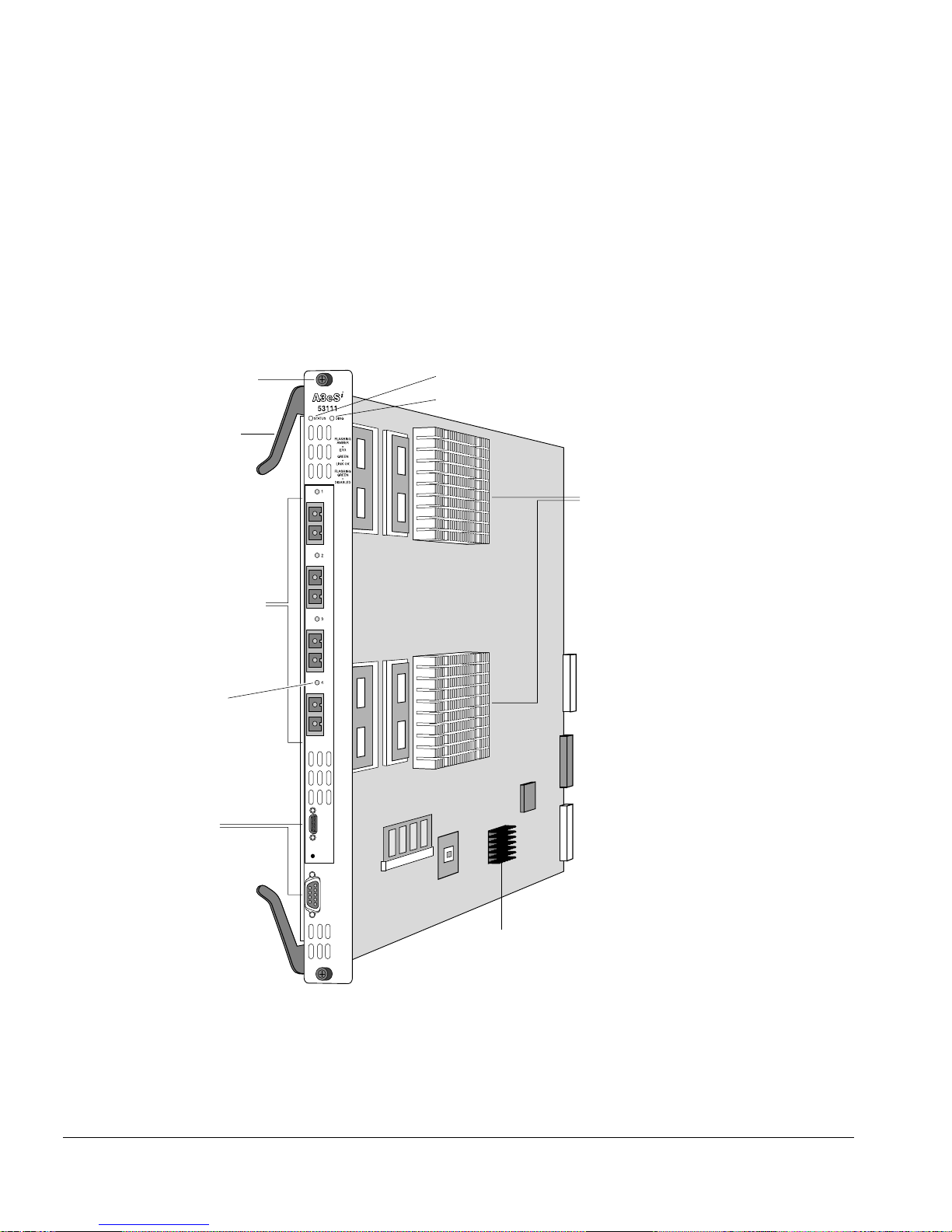
The ATM module consists of a printed circuit board mounted on a metal carrier that
acts as the insertion vehicle in a BlackDiamond 6800 series switch (see Figure 1-1). The
module carrier also includes ejector/ injector handles and captive retaining screws at
each end of the module front panel. The module o ccupies one slot in a BlackD iamond
6800 series switch.
Captive
retaining screw
Ejector/injector
handle
Network interface ports
Four on OC-3 ATM module
Port status LED
(one per port)
Module status LED
Module diagnostics LED
Network processors
and heat sinks
Service ports
Figure 1-1: ATM modu l e
1-4 Asynchronous Transfer Mod e (ATM) Module Insta llation and Us er Guide
General Purpose Processor (GPP)
ATM_002

About the ATM Module
The ATM module has the following key components:
• Two high-performance network processors
• A General Purpose Processor (GPP) subsystem
The network processors are programmable devices that partici pate with the Extreme “i”
chipset to support expanded functio nality, features, and fl exibility.
The GPP subsystem ha ndles system control and I/ O module managem ent functions.
The GPP subsystem resides outside of the I/O mo dule data path to optimize
performance.
ATM Module LED Indicators
The ATM module is equipped with two module-level LED indicators (STATUS and
DIAG) and one port-level LED indicator for each network interface port on the ATM
module (see Figure 1-2).
The STATUS LED indicator is located near the top end of the ATM module front panel,
near the ejector/injector handle. This LED indicator is a bi-color LED (displaying in
either green or amber) that signals the operating status of the module as a whole.
The DIAG LED indicator is located beside the STAT US LED. This LED is a single-color
LED (displaying in amb er only) tha t flashes amber when diagnos tics are running on th e
module, and is solid amber if the module fails the diagnostics.
The port-level LED is an LED next to the port number identifying each fiber optic
network interface connector on the front panel of the module. The port LED is a bi -color
LED (displaying in eit her green or amber) that signals the opera ting status of that
network interface port.
For more information on ATM module LED states and thei r use in troubleshooting
ATM m odule problems, see “Verifying the Module Installa tion” on page 2-10.
Service Ports
The ATM module is equipped with tw o front-panel service ports: one port is a DB-9
connector; the other is a micro HD-15 co nnector (see Figure 1-2). Bo th ports are reserved
for use only by Extreme Networks technical support personne l for diagnostic purposes.
Asynchronous Transfer Mode (ATM ) Module Ins tallation and User Guide 1-5
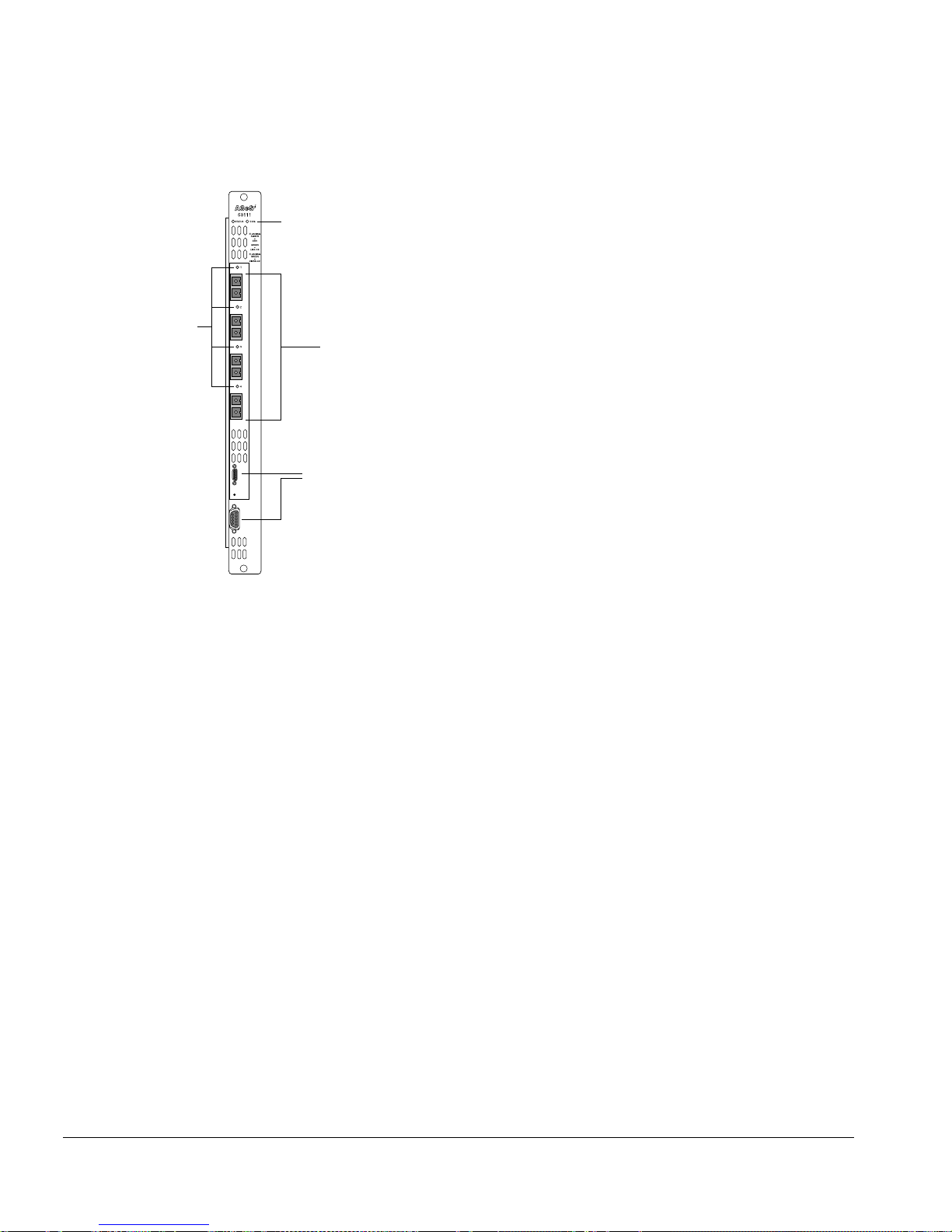
Overview
Port
status
LEDs
Module status LEDs
Network
interface
ports
Service ports
BD_A3
Figure 1-2: Front panel view of the ATM module
Feature Summary
The ATM module supports the fol lowing key networking f unctions:
• Synchronous Optical Network ( SONET) and Synchronous Dig ital Hierarchy (SDH)
modes of operat ion
• IP routing via the Logical Link Control (LLC) Encapsulation for Routed Protocols
compatible w ith RFC 2684 /RFC 1483
• Transparent LAN Services (TLS) over Asynchronous Transfer Mode (ATM) via the
LLC Encapsulation Bridge d Protocols compatible with RFC 2684 /RFC 1483
• Permanent Virtual Circuits (PVCs) may be associated with one or more VLANs
• Routed and bridged encapsulations on the same PVC
• Jumbo frames
• Quality of Service (QoS) and Differentiated Services (DiffServ) features, including
support for:
— Eight ingress queues and eight egress queues per interface
1-6 Asynchronous Transfer Mod e (ATM) Module Insta llation and Us er Guide

About the ATM Module
— Ingress and egress rate shaping and limiti ng
— IEEE 802.1p VLAN priorities
— Weighted RED (WRED) congestion avoidance algor ithm
— Assured Forwarding and Expedited Forwarding RFCs
• Service provider specific features, such as:
— Flexible remapping of DiffServ codepoints
— Flexible remapping of IEEE 802.1Q VLAN IDs
— VLAN tunneling via nested 802.1Q tags
Function Summary
The following sections provide brief descriptio ns of the key functions provided by t he
ATM module. Each of these sectio ns is expanded into greater detail in Chapter 3 .
Asynchronous Transfer Mode (ATM)
ATM is a connection-oriented packet transmissio n technique that is widely used in
existing telecommunications n etworks to transport voice, video, a nd data. ATM uses
fixed size data packets called “cells” which are 53-bytes long and have a header that
includes a connection identifier. The connection identifier makes it possible to support
more than one point-to-point connectio n on a single physical ATM connection. The
switches in an ATM network use the connection identifier in each cell to forward the
cell to the next hop.
Synchronous Optical Network (SONET) and
Synchronous Digital Hierarchy (SDH)
SONET and SDH are the two terms used to identify a time division multiplexing
technology that is optimize d for transporting voice traffic across a digital optical
network, but that is also capable of providing high-speed capacity for transporting data.
The term SONET is used to identify the technolog y used within the North American
digital network. Its standa rds are published by Bellcore and the American National
Standards Institute (ANSI). The term SDH is used to identify the equivalent standard
approved by the International Telecommunication Union (ITU) for use in Europe and
elsewhere in the global digital network. Because SDH evolved out of SONET, the two
standards are closely related and have been widely accepted as a dominant choice for
implementations requiring high transp ort capacity and resistance to failure. The term
Asynchronous Transfer Mode (ATM ) Module Ins tallation and User Guide 1-7

Overview
SONET is used through out this gui de. In instances where there are differences between
SONET and SDH, the differences are explicitly called out.
Jumbo Frames
The ATM module ports provide jumbo frame support th at is similar to that provided by
Ethernet ports on a BlackDiamond 6800 series switch.
Jumbo frames are Ethernet frames that are larger than 1522 bytes, including four bytes
used for the cyclic redundancy check (CRC). Extreme products that use the “i” chipset
support switching and routing of jumbo frames at wi re-speed on all ports.
Jumbo frames are used between endstations that support larger frame sizes for more
efficient transfers of bulk data. Both endstations involved in t he transfer must be
capable of supporting jumbo frames.
QoS and Differentiat ed Serv ices
The ATM module supports eight ingress queues and eight egress queues per port. The
scheduling parameters for these queues (minimum bandwidth, maximum bandwidth,
priority level, etc.) are controlled by QoS profiles that you can customize for in dividual
ingress or egress queues on a specific ATM port.
You can assign frames to queues based on IEEE 802.1p priorities, Differentiated Services
Code Points (DSCPs), or by configuring a QoS profile for the port or VLAN. You can
tailor the DSCP-to-queue mappin g on a per-port basis. Most of the existin g ingress
classification functions, along with the DiffServ replacement functions, are also
supported for ATM ports.
The supported DiffServ functions maximize u ser flexibility while providing all of th e
features needed to support the standard per-hop behaviors (PHBs), including:
• Default
• Class Selector
• Assured Forwarding
• Expedited Forwarding
The ATM module also provides flexible support for the w ell-known Weighted RED
(WRED) congestion avoidance algorithm.
1-8 Asynchronous Transfer Mod e (ATM) Module Insta llation and Us er Guide

About the ATM Module
Service Provider Features
The ATM module provides the following features for service provider environments:
• DSCP mapping
• VLAN ID (VID) tag mapping
• VLAN ID (VID) tag nesting
• VLAN to PVC mapping
DSCP Mapping. You can use the
diffserv dscp-mapping command to configure a
mapped relationship between an input DSCP and an associated output DSCP. Each
ATM port supports three DSCP mapping tables: one o f the tables is used in the ingress
direction; two are used for egress flows (onto the ATM link). The two egress tables are
for the congested and noncongested states, as determined by the RED algorithm. If RED
is not enabled on the ATM port, the egress congested-state mapping table is not used.
In the ingress direction, the input DSCP of a packet received from the ATM link is
replaced by an output DSCP before the packet is forwarded. In the egress direction, the
operation is similar, except that the DSCP mapping occurs before the packet is
transmitted onto the ATM link.
One potential use of the DSCP mappin g capability is to reconcile varying DiffServ
policies at the boundary between autonomous systems, such as at the boundary
between two ISPs. The availability of different tables for the congested and
noncongested states is useful i n marking operations that increase the probabili ty of
packets being dropped during times of congestion, as discussed in the DiffServ Assured
Forwarding RFC (RFC 2597).
VLAN ID (VID) Tag Mapping. An analogous feature has been added for the managing
of 802.1Q tags. The
dot1q tagmapping command provides support for VLAN ID (VID)
mapping tables. Each ATM port supports two VID tables: one table is used in the
ingress direction; the other is used in the egress direction. Each of the tables enables an
input VID to be mapped to an output VID. This feature is useful in reconciling policy
differences at the boundary between the customer and the service provider.
VLAN ID (VID) Tag Nesting. Anot her related enhanceme nt provides support for
nested 802.1Q tags by allowin g a tag push or tag pop attribute to be a ssociated with a
VID. The push attribute indicates that a new tag is to be added to the frame, while the
pop attribute indicates that the t op-level tag is to be removed from the frame. This
capability is augmented by an option t hat allows the 802.1p priority of the fra me to be
either preserved or set to a user-configurable value when a new tag is pushed. These
Asynchronous Transfer Mode (ATM ) Module Ins tallation and User Guide 1-9

Overview
functions make it possible for s ervice providers to tunnel customer-specific VLANs
across a common ATM backbone in a very simple manner.
VLAN to PVC Mapping. VLAN to PVC mapping can be used by service providers to
isolate and provision a customer’s traffic using different VLANs and PVCs for each
customer. Thus, a service provider can securely transport a customer’s Ethernet traffic
across an ATM backbone or vice-versa.
1-10 Asynchronous Transfer Mod e (ATM) Module Insta llation and Us er Guide

2
Installing or Replacing an
ATM Module
This chapter includes information on the following topics:
• Preparing for Installation on page 2-1
• Insert ing and Se curing a Modul e on pag e 2 -7
• Making Network Interface Cable Connections on page 2-9
• Verifying the M odule Installation o n page 2-10
• Troub leshooting on page 2-10
• Removing and Replacin g an I/O Module on pag e 2 -17
Preparing for Installation
This section describes the preparation st eps that you must perform before inserting and
securing an ATM module. This section includes information on the followi ng topics:
• Software and Hardware Version Requirements on page 2-2
• Cables and Connectors on page 2-3
• Safety Information on page 2-3
• To ols on page 2-4
• I/O Module Slot Locations on page 2-4
Asynchronous Transfer Mode (ATM ) Module Ins tallation and User Guide 2-1

Installing or Replacing an ATM Module
Software and Hardware Version Requirements
The ATM module is compatib le with “i”-series MSM modu les and Summit and
“i”-series I/O modules. Fo r the most cu rrent list of I/O m odules suppo rted for use with
the ATM module, consult your release notes.
Software support for the ATM module is provided in an ExtremeWare technology release,
which is a software release providing specialized h ardware support and/or additional
functionality not found in the current mains tream ExtremeWare releases.
The ExtremeWare technology releas e that supports the ATM module includes multiple
software packages. One software package runs on the MSM module, while another
package runs on each ATM module. These software packages are downloaded
independently using the ExtremeWare
package has an associated version number that you can display by using the
show version command. As a recommendation (not a re quirement), the MSM software
package and the ATM module software package should be the same version. To ensure
compatibility, the MSM performs an automati c compatibility check before an ATM
module is activated. In case of incompatibilit y, the ATM ports on the module will not
come up and the
show slot command will indicate that the softw are on the ATM
module is incompatible wit h the software on the MSM.
download image command. Each software
You can also verify compatibility by co mparing the version of the MS M software
package with the version of the ATM module software package. The format of the
software version field of the ExtremeWare software version identifier has been extended
to support technology releases. The following example of the ExtremeWare software
version identifier illustrates the extended version format:
ExtremeWare V6 .1.8 (Bui ld 12) Proj ect IP_ SERV_TECH_REL V 4.1.40
In this example, the technology release-specific version information Project
IP_SERV_TECH_REL V4.1.40 is added to the base ExtremeWare version identifier
ExtremeWare V6.1.8 (Build 12) to form the extended version identifier format. The first
field of the version identifier, ExtremeWare V6.1.8 (Build 12) , identifies the ExtremeWare
software version on which this technolog y release is based. The second field in the
extended version identifier, Project IP_SERV_TECH_REL, is the name of the technology
release. The final field, V4.1.40 is a three-part number that identifies the version of the
technology release. In the example, the first part of the number, 4, is the extended major
version number; the second part of the number, 1, i s the extended minor version number;
the third part of the number, 40, is the extended build version number.
2-2 Asynchronous Transfer Mod e (ATM) Module Insta llation and Us er Guide

Preparing for Insta llation
The MSM software package is compatible with the ATM module software package
when the following condit ions are true:
• Base ExtremeWare version numbers match
• Technology release names match
• Extended major version numbers match
• Extended minor version number of the MSM software package is equa l to or greater
than the extended minor version of the ATM module software package
The extended build number is ignored for compat ibility comparis ons.
For example, MSM software package ExtremeWare V6.1.8 (Build 12) Project
IP_SERV_TECH_REL V4.2.60 is compatible with ATM module software package
ExtremeWare V6.1.8 (Build 12) Project IP_SERV_TECH_REL V4.1.50, but is not compatible
with ATM module software package ExtremeWare V6.1.8 (Build 12) Project
IP_SERV_TECH_REL V4.3.60.
Cables and Connectors
Extreme Networks offers the ATM module in the following co nfiguration:
• A3cSi: four OC-3c/STM-1 single-mo de, intermediate-reach optical interfaces
The A3cSi (single-mode version) operates in the 1310 nanometer (nm) wavelength
window, but at a typi cal maximum cable distance of 15 km o r 9.32 (mi). The ATM
module uses industry-standard duplex SC optical-fiber connectors.
Use the appropriate type of optical-fiber cable to connect the ATM ports of your
BlackDiamond 6800 series switch to another switch or router.
Safety Information
Before you begin the process of installing or replacing an ATM module in a
BlackDiamond 6800 s eries system, read the safety info rmation in this section.
Failure to observe the necessa ry safety guideli nes can lead to personal inj ury or
damage to the equipm ent.
In addition, observe the following sa fety guidelines:
Asynchronous Transfer Mode (ATM ) Module Ins tallation and User Guide 2-3

Installing or Replacing an ATM Module
• All service to components of a Bla ckDiamond 6800 series switch , including I/O
modules, should be performed by trai ned service personnel only. S ervice personnel
are persons having appropriate technical training and experience necessary to be
aware of the hazards to which they are exposed in performing a task and of
measures to minimize the danger to themselves or o ther persons.
The ATM module uses electronic c omponents that are sens itive to static
electricity. Electrostatic discharge (ESD) or iginating from you or from objects
around you can damage thes e components. Exercise every possible
precaution to prevent ESD when worki ng around printed c ircuit assemblies.
Keep all printed circui t assemblies in protective ESD-pr eventive sacks or
place them on antis tatic mats until you are ready to install them. Wear an
ESD-preventive wrist strap and ensur e that the leash is se curely grounded
before handling a bare pr inted circuit asse mbly.
• This device contains fiber optic ports. To protect your eyes, you should never look at
the fiber optic ports while they are on, or look directly at the fiber cable ends when
they are on.
• This module is a Class 1 laser device.
Tools
You need the following tools to in stall an Extreme Networks I/O mod ule in a
BlackDiamond 6800 series chassis.
• ESD-preventive wrist strap and grounding leash that is p rovided with the
BlackDiamond 6800 series chassis.
• Number 1 Phillips-head screwdriver.
• Optical-fiber cable of the type appropriate to the I/O module version yo u plan to
install (see “Cables and Connectors” on pag e 2-3 for more informa tion abo ut cable
and connector requirements).
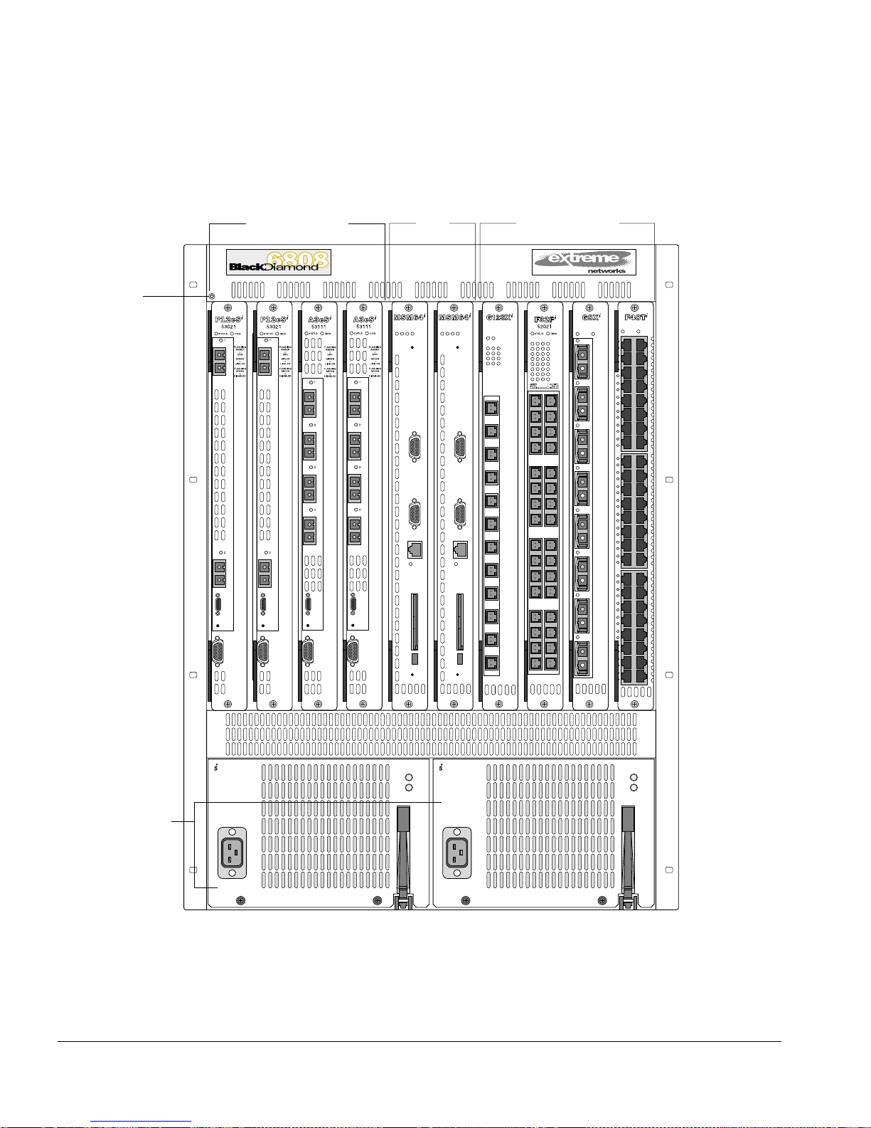
I/O Module Slot Locations
Figure 2 -1 show s the I/ O modu le slot loca tions i n the Bla ckDiamon d 6800 series cha ssis.
You can install the ATM module in any of the numbered slots labeled 1 through 8. I/O
modules do not fit in slots A or B. When y ou are installing a new ATM module, you
must first remove the blank filler from the avai lable slot.
2-4 Asynchronous Transfer Mod e (ATM) Module Insta llation and Us er Guide

Preparing for Insta llation
To ensure a suf ficient flow of cooling air across the component side of the ATM
module, install the ATM module in the BlackDia mond 6 800 ser ies cha ssis so that
another module, a blank filler, or the far right chassis wall covers the compone nt
side of the module.
Asynchronous Transfer Mode (ATM ) Module Ins tallation and User Guide 2-5
Installing or Replacing an ATM Module
ESD wrist strap
connector
1234AB5678
I/O module slots
MSM module
slots
I/O module slots
50015 50015
S
M
E
E
Y
N
R
S
S
V
R
T
R
CONSOLE
MODEM
MGMT
LINK /
ACTIVITY
PCMCIA
S
M
Y
S
S
51040
E
E
N
R
V
R
T
R
ST
D
ATU
CONSOLE
1
5
2
6
3
7
4
8
AMBER
GREEN
FLASHING GREEN
1
IAG
S
9
10
11
12
17
1
9
10
18
2
11
19
3
20
12
4
21
13
5
=
ACTIVITY
22
14
6
=
LINK OK
=
DISABLED
23
15
7
24
16
8
51032
1
25
26
27
28
29
30
31
32
2
17
3
DIAGSTATUS
ACTIVITY
LINK OK
FLASHING
DISABLED
52011
DIAGSTATUS
AMBER
=
GREEN
=
GREEN
=
2
4120
8524
12928
21
4
5
25
6
7
29
8
ACTIVITY
3
4
MODEM
5
6
MGMT
7
LINK /
8
9
10
11
PCMCIA
12
161332
POWER
Power supplies
V-50/60Hz
200-240V, 15A
Figure 2-1: Slot l ocations in a BlackDiamo nd 6800 series ch assis
2-6 Asynchronous Transfer Mod e (ATM) Module Insta llation and Us er Guide
50021
DC OUT
AC IN
POWER
V-50/60Hz
200-240V, 15A
50021
DC OUT
AC IN
ATM_003
 Loading...