

Extreme Networks BlackDiamond 12804, BlackDiamond 12802 User Manual

BlackDiamond 12800 Series Switches
Hardware Installation Guide
BlackDiamond 12802 Switch
BlackDiamond 12804 Switch
Extreme Networks, Inc.
3585 Monroe Street
Santa Clara, California 95051
(888) 257-3000
(408) 579-2800
http://www.extremenetworks.com
Published: June 2008
Part number: 104002-00 Rev. 03

AccessAdapt, Alpine, Altitude, BlackDiamond, EPICenter, Essentials, Ethernet Everywhere, Extreme Enabled,
Extreme Ethernet Everywhere, Extreme Networks, Extreme Standby Router Protocol, Extreme Turbodrive, Extreme
Velocity, ExtremeWare, ExtremeWorks, ExtremeXOS, Go Purple Extreme Solution, ScreenPlay, Sentriant,
ServiceWatch, Summit, SummitStack, Triumph, Unified Access Architecture, Unified Access RF Manager, UniStack,
the Extreme Networks logo, the Alpine logo, the BlackDiamond logo, the Extreme Turbodrive logo, the Summit
logos, the Powered by ExtremeXOS logo, and the Color Purple, among others, are trademarks or registered
trademarks of Extreme Networks, Inc. or its subsidiaries in the United States and/or other countries.
Adobe, Flash, and Macromedia are registered trademarks of Adobe Systems Incorporated in the U.S. and/or other
countries. AutoCell is a trademark of AutoCell. Avaya is a trademark of Avaya, Inc. Internet Explorer is a registered
trademark of Microsoft Corporation. Mozilla Firefox is a registered trademark of the Mozilla Foundation. sFlow is a
registered trademark of sFlow.org. Solaris and Java are trademarks of Sun Microsystems, Inc. in the U.S. and other
countries.
Specifications are subject to change without notice.
All other registered trademarks, trademarks, and service marks are property of their respective owners.
© 2007, 2008 Extreme Networks, Inc. All Rights Reserved.
For safety compliance information, see Appendix A, “Safety Information.”
2
BlackDiamond 12800 Series Switches Hardware Installation Guide

Table of Contents
Preface........................................................................................................................................... 9
Introduction ...............................................................................................................................9
Conventions................................................................................................................................9
Related Publications .................................................................................................................10
Part 1: BlackDiamond 12800 Series Switches
Chapter 1: About the BlackDiamond 12800 Series Switches............................................................ 15
Overview of the BlackDiamond 12800 Series Switches .................................................................15
Full-Duplex Support ............................................................................................................15
Management Ports ..............................................................................................................16
External Compact Flash Memory Card ...................................................................................16
BlackDiamond 12804 Switch Chassis.........................................................................................16
BlackDiamond 12802 Switch Chassis.........................................................................................18
Chapter 2: BlackDiamond 12800 Series Modules ........................................................................... 19
Overview of the BlackDiamond 12800 Series Modules..................................................................19
BlackDiamond 12800 Series MSMs............................................................................................20
Software Requirements........................................................................................................20
Redundant MSM Activity (BlackDiamond 12804 Switch)........................................................21
MSM LEDs .........................................................................................................................21
Features of the BlackDiamond 12800 MSMs.........................................................................22
BlackDiamond 12800 Series I/O Modules ...................................................................................23
I/O Module LEDs.................................................................................................................24
Port LEDs on I/O Modules ....................................................................................................24
GM-20T I/O Module ............................................................................................................25
GM-20T LEDs...............................................................................................................25
GM-20XT and GM-20XTR I/O Modules ..................................................................................25
GM-20XT and GM-20XTR LEDs ......................................................................................26
XM-2X and XM-2XR I/O Modules ..........................................................................................26
XM-2X and XM-2XR LEDs ..............................................................................................27
XM-2HR I/O Module ............................................................................................................28
XM-2HR LEDs ..............................................................................................................28
Chapter 3: Extreme Networks Power Supply Units for BlackDiamond Switches.................................. 29
Overview of BlackDiamond 12800 Series Power Supplies .............................................................29
Extreme Networks 1200 W DC PSU ............................................................................................30
Minimum Software Required ................................................................................................31
LEDs..................................................................................................................................31
Extreme Networks 700/1200 W AC PSU .....................................................................................32
LEDs..................................................................................................................................33
Power Supply Cords.............................................................................................................33
Fuse ..................................................................................................................................33
Specifications.....................................................................................................................34
BlackDiamond 12800 Series Switches Hardware Installation Guide
3

Table of Contents
Extreme Networks 325 W DC Power Supply.................................................................................34
Minimum Software Required ................................................................................................35
LEDs..................................................................................................................................35
Fuse ..................................................................................................................................36
Specifications.....................................................................................................................36
Extreme Networks 325 W AC Power Supply .................................................................................36
LEDs..................................................................................................................................37
Replacing AC Power Supply Cords ..............................................................................................37
Fuse ..................................................................................................................................38
Part 2: Installing BlackDiamond Switches and Modules
Chapter 4: Site Preparation............................................................................................................ 41
Planning Your Site ....................................................................................................................41
Meeting Site Requirements ........................................................................................................42
Operating Environment Requirements ...................................................................................42
Building and Electrical Codes.........................................................................................42
Wiring Closet Considerations ..........................................................................................43
Temperature .................................................................................................................43
Humidity ......................................................................................................................44
BlackDiamond Family Chassis Spacing Requirements.......................................................44
Airflow Requirements ....................................................................................................44
Electrostatic Discharge ..................................................................................................45
Rack Specifications and Recommendations ...........................................................................46
Mechanical Recommendations for the Rack .....................................................................46
Protective Grounding for the Rack...................................................................................46
Space Requirements for the Rack ...................................................................................47
Securing the Rack .........................................................................................................47
Evaluating and Meeting Cable Requirements ...............................................................................48
Cabling Standards ...............................................................................................................48
Cable Labeling and Record Keeping......................................................................................48
Installing Cable...................................................................................................................49
Fiber Optic Cable ..........................................................................................................50
Cable Distances ............................................................................................................51
RJ-45 Connector Jackets .....................................................................................................52
Radio Frequency Interference...............................................................................................53
Meeting Power Requirements .....................................................................................................53
Power Supply Requirements.................................................................................................53
AC Power Cable Requirements..............................................................................................54
Replacing the Power Cable.............................................................................................54
Uninterruptible Power Supply Requirements ..........................................................................54
Selecting a UPS............................................................................................................55
Calculating Volt-Amperage Requirements.........................................................................55
UPS Transition Time .....................................................................................................55
Applicable Industry Standards....................................................................................................55
Chapter 5: Installing the BlackDiamond 12800 Series Chassis ........................................................ 57
Unpacking the BlackDiamond 12804 Chassis..............................................................................58
Rack-Mounting the BlackDiamond 12804 Chassis .......................................................................60
Pre-installation Requirements...............................................................................................61
4
BlackDiamond 12800 Series Switches Hardware Installation Guide

Table of Contents
Attaching the BlackDiamond 12804 Mid-Mount Brackets .......................................................61
Rack-Mounting the BlackDiamond 12804 Chassis .................................................................62
Unpacking the BlackDiamond 12802 Chassis..............................................................................64
Rack-Mounting the BlackDiamond 12802 Chassis .......................................................................66
Required Tools and Equipment.............................................................................................66
Front-Mounting a BlackDiamond 12802 Chassis....................................................................66
Mid-Mounting a BlackDiamond 12802 Chassis......................................................................67
Grounding the BlackDiamond 12800 Series Chassis ....................................................................68
Initial Management Access ........................................................................................................70
Connecting Equipment to the Console Port ..................................................................................70
Logging In for the First Time ......................................................................................................71
Chapter 6: Installing Power Supply Units ........................................................................................73
Safety ......................................................................................................................................73
BlackDiamond PSU Compatibility ...............................................................................................74
Extreme Networks 1200 W DC PSU ............................................................................................74
Minimum Software Required ................................................................................................75
Pre-Installation Requirements ..............................................................................................75
Installing the DC Wiring .......................................................................................................75
Installing an Extreme Networks 1200 W DC PSU ...................................................................76
Removing an Extreme Networks 1200 W DC PSU...................................................................79
Front Panel LEDs ................................................................................................................80
Extreme Networks 700/1200 W AC PSU .....................................................................................81
Pre-Installation Requirements ..............................................................................................81
Installing an Extreme Networks 700/1200 W AC PSU.............................................................81
Removing an Extreme Networks 700/1200 W AC PSU............................................................83
Front Panel LEDs ................................................................................................................84
Power Supply Cords.............................................................................................................84
Fuse ..................................................................................................................................85
Using the BlackDiamond12804 AC Power Cord Retainer Channel..................................................85
Pre-Installation Requirements ..............................................................................................85
Installing the BlackDiamond 12804 AC Power Cord Retainer Channel......................................85
Removing the BlackDiamond 12804 AC Power Cord Retainer Channel.....................................88
Extreme Networks 325 W DC Power Supply.................................................................................88
Minimum Software Required ................................................................................................88
Pre-Installation Requirements ..............................................................................................89
Installing the DC Wiring .......................................................................................................89
Installing an Extreme Networks 325 W DC PSU .....................................................................90
Removing an Extreme Networks 325 W DC PSU.....................................................................93
LEDs..................................................................................................................................94
Extreme Networks 325 W AC Power Supply .................................................................................94
Pre-Installation Requirements ..............................................................................................94
Installing an Extreme Networks 325 W AC PSU .....................................................................95
Installing Retaining Brackets and Connecting Power...............................................................97
Removing an Extreme Networks 325 W AC PSU.....................................................................99
Front Panel LEDs ................................................................................................................99
Power Supply Cords...........................................................................................................100
Fuse ................................................................................................................................100
Chapter 7: Installing Modules and Connecting Cables ................................................................... 101
BlackDiamond 12800 Series Switches Hardware Installation Guide
5

Table of Contents
Module Slot Assignments.........................................................................................................101
Distinguishing a BlackDiamond 12800 Series MSM from an I/O Module ......................................102
Installing a BlackDiamond 12800 Series Module .......................................................................102
Making Network Interface Cable Connections.............................................................................105
Installing a Backup MSM.........................................................................................................105
Verifying the Module Installation ..............................................................................................106
Displaying Slot Status Information ......................................................................................106
Removing a BlackDiamond 12800 Series Module ......................................................................106
BlackDiamond Series Blank Front Panels ..................................................................................108
Installing a Blank Front Panel ............................................................................................108
Removing a Blank Front Panel............................................................................................109
Installing or Removing an External Compact Flash Memory Card..................................................111
Part 3: BlackDiamond Maintenance Procedures
Chapter 8: Replacing BlackDiamond 12800 Series Chassis Components........................................ 115
Safety Information ..................................................................................................................115
Replacing a BlackDiamond 12804 PSU/Fan Controller ...............................................................115
Pre-Installation Requirements ............................................................................................116
Removing a BlackDiamond 12804 PSU/Fan Controller .........................................................116
Installing a Replacement BlackDiamond 12804 PSU/Fan Controller ......................................117
Replacing a BlackDiamond 12802 PSU/Fan Controller ...............................................................118
Pre-installation Requirements.............................................................................................118
Removing a BlackDiamond 12802 PSU/Fan Controller .........................................................118
Installing the Replacement PSU/Fan Controller ....................................................................119
Replacing a BlackDiamond 12804 Fan Tray ..............................................................................119
Pre-Installation Requirements ............................................................................................119
Removing the Fan Tray ......................................................................................................120
Installing the Replacement BlackDiamond 12804 Fan Tray ..................................................121
Replacing the BlackDiamond 12802 Fan Tray ...........................................................................121
Pre-installation Requirements.............................................................................................122
Removing the BlackDiamond 12802 Fan Tray .....................................................................122
Installing the Replacement BlackDiamond 12802 Fan Tray ..................................................123
Chapter 9: Repacking a BlackDiamond Chassis............................................................................. 125
Safety Information ..................................................................................................................125
Repacking the BlackDiamond 12804 Chassis ............................................................................126
Repacking the BlackDiamond 12802 Chassis ............................................................................129
Part 4: Appendixes
Appendix A: Safety Information .................................................................................................... 133
Considerations Before Installing ...............................................................................................133
Installing Power Supply Units...................................................................................................134
Maintenance Safety.................................................................................................................135
General Safety Precautions ......................................................................................................135
Cable Routing for LAN Systems ................................................................................................136
PoE Devices ...........................................................................................................................136
6
BlackDiamond 12800 Series Switches Hardware Installation Guide

Table of Contents
Selecting Power Supply Cords ..................................................................................................136
Battery Replacement and Disposal............................................................................................138
Fiber Optic Ports—Optical Safety .............................................................................................138
GBIC, SFP (Mini-GBIC), XENPAK, and XFP Regulatory Compliance .......................................139
Appendix B: Technical Specifications .......................................................................................... 147
BlackDiamond 12804 Switch...................................................................................................147
BlackDiamond 12802 Switch...................................................................................................149
Power Supplies for the BlackDiamond 12800 Series Switches ....................................................151
Connector Pinouts...................................................................................................................153
Index .......................................................................................................................................... 155
BlackDiamond 12800 Series Switches Hardware Installation Guide
7

Table of Contents
8
BlackDiamond 12800 Series Switches Hardware Installation Guide

Preface
This preface provides an overview of this guide, describes guide conventions, and lists other
publications that might be useful.
WARNING!
Service to all equipment should be performed by trained and qualified service personnel only. Before installing or
removing any components of the system, or before carrying out any maintenance procedures, you must thoroughly
read the safety information provided in Appendix A of this guide. Failure to follow this safety information can lead to
personal injury or damage to the equipment.
Introduction
This guide provides the required information to install Extreme Networks® BlackDiamond® 12800 series
switches. This guide also contains information about site preparation, switch functionality, and switch
operation.
This guide is intended for use by network administrators responsible for installing and setting up
network equipment. It assumes a basic working knowledge of:
● Local area networks (LANs)
● Ethernet concepts
● Ethernet switching and bridging concepts
● Routing concepts
● Simple Network Management Protocol (SNMP)
See the ExtremeXOS 12.0 Concepts Guide and the ExtremeXOS 12.0 Command Reference Guide for
information about configuring Extreme Networks BlackDiamond 12800 series switches.
NOTE
If the information in the installation note or release note shipped with your Extreme Networks switch differs from the
information in this guide, follow the installation or release note.
Conventions
Tabl e 1 and Tab le 2 list conventions used throughout this guide.
BlackDiamond 12800 Series Switches Hardware Installation Guide
9
Preface
Table 1: Notice icons
Icon Notice Type Alerts you to...
Note Important features or instructions.
Caution Risk of personal injury, system damage, or loss of data.
Warning Risk of severe personal injury.
Table 2: Text conventions
Convention Description
Screen displays This typeface represents information as it appears on the screen, or command
The words “enter”
and “type”
[Key] names Key names appear in text in one of two ways:
Words in italicized type Italics emphasize a point of information or denote new terms at the place where
syntax.
When you see the word “enter” in this guide, you must type something, and then
press the Return or Enter key. Do not press the Return or Enter key when an
instruction simply says “type.”
• Referenced by their labels, such as “the Return key” or “the Escape key”
• Written with brackets, such as [Return] or [Esc]
If you must press two or more keys simultaneously, the key names are linked with a
plus sign (+). Example:
Press [Ctrl]+[Alt]+[Del].
they are defined in the text.
10
Related Publications
The Extreme Networks ExtremeXOS™ switch documentation set includes:
●
ExtremeXOS 12.0 Concepts Guide
●
ExtremeXOS 12.0 Command Reference Guide
●
ExtremeXOS 12.0 Release Notes
●
BlackDiamond 8800 Series Switches Hardware Installation Guide
●
BlackDiamond 10808 Switch Hardware Installation Guide
●
Summit Family Switches Hardware Installation Guide
●
Extreme Networks Pluggable Interfaces Hardware Installation Guide
Documentation for Extreme Networks products is available from the Extreme Networks website at the
following location:
http://www.extremenetworks.com/services/documentation
BlackDiamond 12800 Series Switches Hardware Installation Guide

Related Publications
You can select and download the following Extreme Networks documentation from the Documentation
Overview page:
● Software User Guides
● Hardware User Guides
You can find archived user guides for software at:
http://www.extremenetworks.com/services/documentation/swuserguides.asp
You can also find archived installation guides for hardware at:
http://www.extremenetworks.com/services/documentation/hwuserguides.asp
BlackDiamond 12800 Series Switches Hardware Installation Guide
11

Preface
12
BlackDiamond 12800 Series Switches Hardware Installation Guide

1 BlackDiamond 12800 Series Switches


1 About the BlackDiamond 12800 Series
Switches
This chapter includes the following sections:
● Overview of the BlackDiamond 12800 Series Switches on page 15
● BlackDiamond 12804 Switch Chassis on page 16
● BlackDiamond 12802 Switch Chassis on page 18
For information about the I/O modules and management modules (MSMs) for the BlackDiamond 12800
series switches, see Chapter 3, “BlackDiamond 12800 Series Modules.”
For information about installing the BlackDiamond switches, see Chapter 2, “Installing the
BlackDiamond 12800 Series Chassis.”
Overview of the BlackDiamond 12800 Series Switches
The BlackDiamond switches are chassis-based, Ethernet service core switches designed for core
applications. For more information about configuring a BlackDiamond switch, see the ExtremeXOS 12.0
Concepts Guide and the ExtremeXOS 12.0 Command Reference Guide.
The features of these switches include:
● I/O modules that are hot-swappable and include Gigabit Ethernet copper ports (10/100/1000) and
Gigabit Ethernet fiber ports (SFP), or 10 Gigabit Ethernet ports
● Management Switch Fabric Modules (MSMs) that provide the active switching fabric and CPU
control subsystem
● Redundant, load-sharing, hot-swappable power supplies
● Field-replaceable, hot-swappable fan trays
● Auto-negotiation for half-duplex or full-duplex operation on 10/100/1000 Mbps ports
● Load sharing on multiple ports
The BlackDiamond 12800 series switches include two chassis models:
● BlackDiamond 12804 switch chassis (see page 16)
● BlackDiamond 12802 chassis (see page 18)
Full-Duplex Support
Extreme Networks switches provide full-duplex support for all ports. Full-duplex support means that
frames can be transmitted and received simultaneously, which, in effect, doubles the bandwidth
available on a link. Most ports on an Extreme Networks switch will auto-negotiate duplex in the default
configuration. Gigabit Ethernet fiber ports and 10 Gigabit Ethernet ports operate only in full-duplex
mode in accordance with technical standards.
BlackDiamond 12800 Series Switches Hardware Installation Guide
15

About the BlackDiamond 12800 Series Switches
Management Ports
Each BlackDiamond series Management Switch Fabric Module (MSM) has a 10/100BASE-TX Ethernet
management port. This port allows you to communicate directly with the central processing unit (CPU)
of the switch. You can plug an Ethernet cable directly from your laptop into the management port, for
direct access into the switch. This access allows you to view and locally manage the switch
configurations.
External Compact Flash Memory Card
All MSMs in the BlackDiamond family include a compact flash slot next to the console port on the
MSM. This slot accepts a compact flash memory card, which can be used to download a new version of
ExtremeXOS and for other functions, including capturing debug information and core dump files. See
the ExtremeXOS 12.0 Concepts Guide for more information regarding the use of the external compact
flash memory card.
The external compact flash slot supports third party compact flash cards.
NOTE
You must use an industrial-grade compact flash card in the external compact flash slot of the MSM.
BlackDiamond 12804 Switch Chassis
The BlackDiamond 12804 chassis consists of the following components:
● One 6-slot chassis with backplane
● Four dedicated I/O module slots, labeled 1, 2, 5, and 6
● Two MSM slots, labeled 3/A and 4/B
● Up to six SSI redundant AC/DC power supplies, accessed from the front of the unit
● One fan tray, accessed from the front right of the unit
● One connector for an ESD-preventive wrist strap
● Two PSU/fan controllers that collect and report data from the installed power supply units and the
BlackDiamond fan tray. The PSU/fan controllers intervene in the event of power inconsistencies and
provide primary/backup redundancy if a BlackDiamond 12804 PSU/fan controller fails.
Figure 1 shows a BlackDiamond 12804 chassis equipped with one MSM and three optional I/O
modules.
16
BlackDiamond 12800 Series Switches Hardware Installation Guide
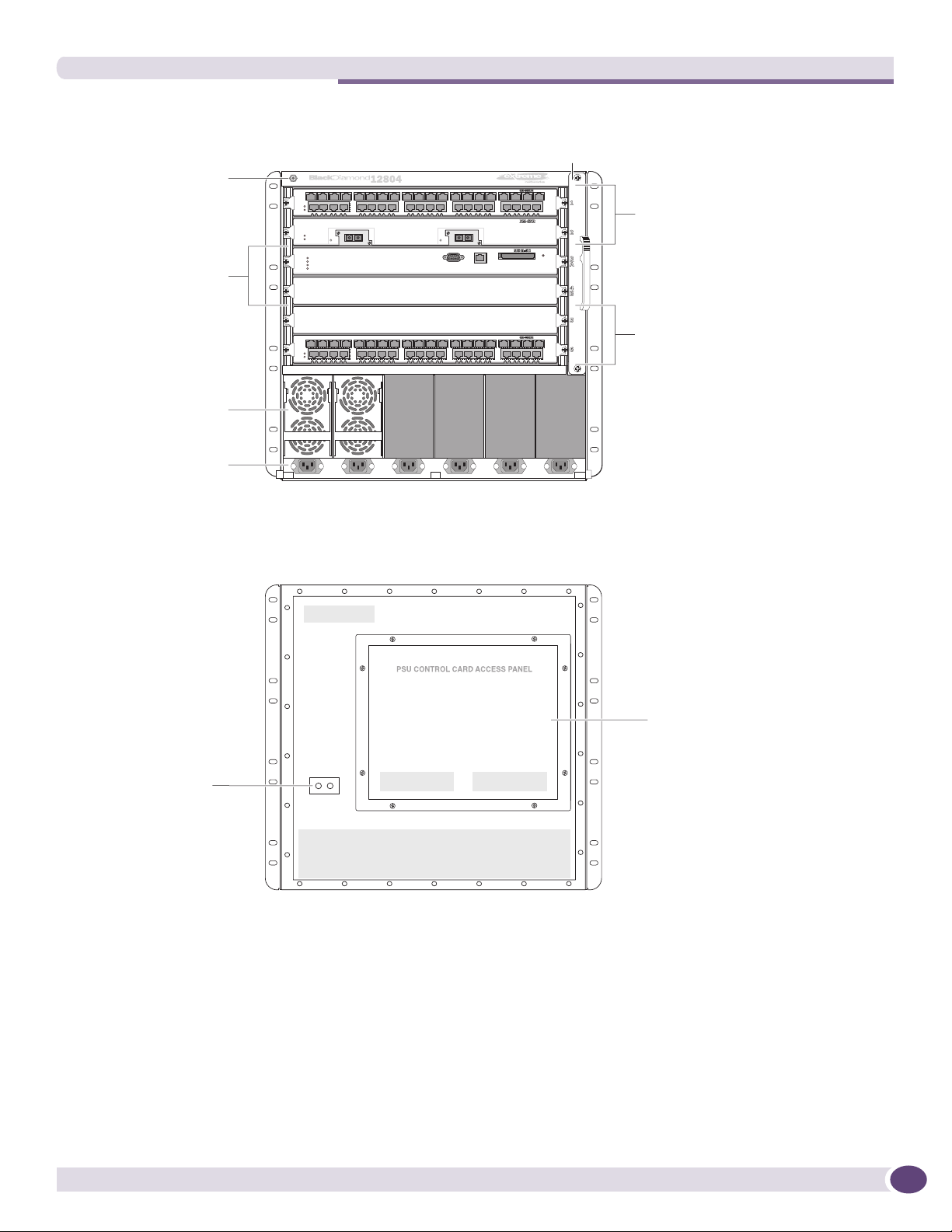
Figure 1: Front of the BlackDiamond 12804 Chassis
BlackDiamond 12804 Switch Chassis
ESD wrist strap
Fan tray
connector
MSM module slots
Power supplies
Power cord
connectors
Figure 2 shows the rear view of the BlackDiamond 12804 chassis.
Figure 2: Rear Panel of the BlackDiamond 12804 Chassis
I/O module
slots
I/O module
slots
EX_127
EX_157
Grounding point
The rear panel of the BlackDiamond 12804 chassis provides:
● Chassis serial number
● Ethernet MAC address of the switch
● Symbols of safety certification
● Access to the PSU/fan controllers
● Attachment point for optional chassis ground
PSU / fan
controllers
EX_128A
BlackDiamond 12800 Series Switches Hardware Installation Guide
17
About the BlackDiamond 12800 Series Switches
BlackDiamond 12802 Switch Chassis
The BlackDiamond 12802 chassis consists of the following components:
● One 3-slot chassis with backplane
● Two dedicated I/O module slots, labeled 1 and 2
● One MSM slot, labeled MSM
● Up to three redundant AC or DC power supplies, accessed from the back of the unit
● One fan tray, accessed from the back left of the unit
● One connector for an ESD-preventive wrist strap
● One PSU/fan controller that collects and reports data from the power supply units and the fan tray.
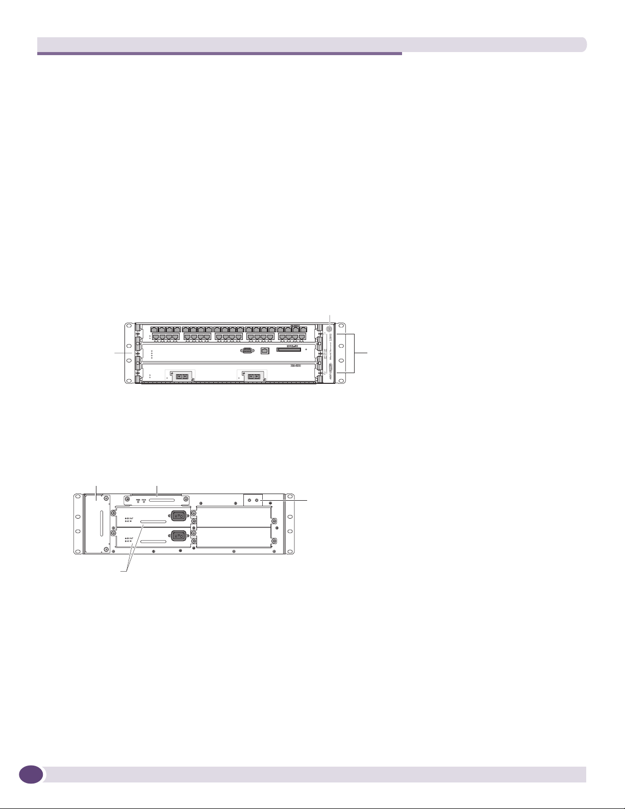
Figure 3 shows a BlackDiamond 12802 chassis equipped with one MSM and two I/O modules.
Figure 3: Front of the BlackDiamond 12802 Chassis
ESD wrist strap
connector
MSM slot
Figure 4 shows the rear panel of the BlackDiamond 12802 chassis.
Figure 4: Rear Panel of the BlackDiamond 12802 Chassis
PSU/fan controller
Fan tray
Power
supplies
The rear panel of the BlackDiamond 12802 chassis provides:
● Access to the fan tray
● Access to the PSU/fan controller module
● Four bays for installing power supplies
● Attachment point for optional chassis ground
module
Grounding
point
BD_142A
I/O module
slots
BD_141
18
The bottom of the chassis has a label showing safety certification symbols and the Ethernet MAC
address of the switch. The chassis serial number is on the side near the back of the chassis.
BlackDiamond 12800 Series Switches Hardware Installation Guide

2 BlackDiamond 12800 Series Modules
This chapter includes the following sections:
● Overview of the BlackDiamond 12800 Series Modules on page 19
● BlackDiamond 12800 Series MSMs on page 20
● BlackDiamond 12800 Series I/O Modules on page 23
For information about installing modules in a BlackDiamond 12800 series switch, see Chapter
4, “Installing Modules and Connecting Cables.”
Overview of the BlackDiamond 12800 Series Modules
Two sets of modules are available for the BlackDiamond 12800 series switch: the 12800 series of
modules and the 12800 R series of modules. All BlackDiamond 12800 series I/O modules and
management system modules (MSMs) use the Extreme Networks 4th Generation ASICs that enable
high availability, advanced security, and deterministic performance independent of traffic mix. The
BlackDiamond 12800 series R-series modules further provide hierarchical QoS and larger MAC address,
IP route, and ACL capacity for network designs that need the advanced QoS features and scale. The
R-series modules support rate limiting, which is the ability to control bandwidth throughout the
network. For complete details about rate limiting, refer to the ExtremeXOS 12.0 Concepts Guide. Ta ble 3
lists the modules available in each series.
Table 3: Modules for the BlackDiamond 12800 Series Switches
Module Type BlackDiamond 12800 Series BlackDiamond 12800 R Series
MSM MSM-5 module MSM-5R module
MSM-6R module
I/O module XM-2X I/O module XM-2XR I/O module
GM-20XT I/O module GM-20XTR I/O module
GM-20T I/O module
XM-2HR I/O module
CAUTION
Do not attempt to mix modules across Extreme Networks product lines. BlackDiamond 12800 series modules are for
use only in a BlackDiamond 12802 or 12804 switch. When a BlackDiamond 12800 series switch is in use,
ExtremeXOS software will not recognize a module from a different product line.
NOTE
The BlackDiamond R-series modules must be used together to take advantage of the higher feature set and scale.
The ExtremeXOS software recognizes the MSM type installed in your BlackDiamond 12800 series switch and only
allows use of compatible I/O modules from the same series. An error message is displayed if you attempt to mix
modules.
BlackDiamond 12800 Series Switches Hardware Installation Guide
19

BlackDiamond 12800 Series Modules
BlackDiamond 12800 Series MSMs
The BlackDiamond 12800 series MSMs are the MSM-5 module, MSM-5R module, and MSM-6R module.
These MSMs provide the active switching fabric and CPU control subsystem for the switch. The
BlackDiamond 12802 chassis has one dedicated MSM slot; the BlackDiamond 12804 chassis has two
dedicated MSM slots. One MSM is required for switch operation; however, adding a second MSM to a
BlackDiamond 12804 chassis increases system availability through redundancy. Each MSM provides
192 Gbps of switching throughput through three ASICs. Each module also contains a temperature
sensor, nonvolatile random-access memory (NVRAM), and a real-time clock.
The MSM-5 and the MSM-5R and MSM-6R modules support different sizes of Ternary Content
Addressable Memory (TCAM). The MSM-5R and MSM-6R modules have more memory available for
routing tables, learned MAC addresses, and access control lists (ACLs). For specific details about
memory allocation, refer to the data sheet for each module.
CAUTION
You must use compatible MSMs and I/O modules from a single BlackDiamond 12800 module series. Do not attempt
to mix MSMs from the two different series. The ExtremeXOS software recognizes the MSM type installed in your
BlackDiamond 12800 series switch and only allows use of a second MSM of the same type and compatible I/O
modules from the same series. An error message is displayed if you attempt to mix module series.
Software Requirements
Tabl e 4 lists the minimum software revision required for MSMs in the BlackDiamond 12800 series
switches.
Table 4: Required Software for BlackDiamond 12800 Series MSMs
Switch Model MSM Model Required Software
BlackDiamond 12804 MSM-5, MSM-5R ExtremeXOS 11.4.1 or later
MSM-6R ExtremeXOS 12.0.2 or later
BlackDiamond 12802 MSM-5, MSM-5R ExtremeXOS 12.0.1 or later
MSM-6R ExtremeXOS 12.0.2 or later
Make sure your BlackDiamond switches are running the required software version to support the
switch model and MSM type. The MSM-6R requires ExtremeXOS 12.0.2 or later. A BlackDiamond 12802
switch running software earlier than version 12.0.1 will not be fully operational.
To upgrade the software in your BlackDiamond 12802 switch, access the latest image at the Extreme
Networks support website at
instructions in the ExtremeXOS Release Notes.
NOTE
http://www.extremenetworks.com/services/services-hub.aspx. Follow the upgrade
20
The MSM slot in the BlackDiamond 12802 switch is labeled MSM on the front panel. The ExtremeXOS software
refers to this MSM as MSM-A in all related displays and command output.
BlackDiamond 12800 Series Switches Hardware Installation Guide

BlackDiamond 12800 Series MSMs
Redundant MSM Activity (BlackDiamond 12804 Switch)
The BlackDiamond 12804 switch can operate with a single MSM installed, providing full bandwidth
with this single MSM. When you install a second MSM, one of the MSMs operates as the primary, and
the other becomes the secondary or backup.
The primary MSM is responsible for upper-layer protocol processing and system management
functions. The MSMs in the BlackDiamond 12804 switch are not load sharing. MSM(A) or MSM(B)
handles packets while the other MSM is idle.
When you save the switch configuration, it is saved to all MSMs.
Selection of the primary MSM occurs automatically. The following examples describe the selection
process:
● When a BlackDiamond 12804 switch boots with two MSMs installed, the MSM in slot 3/A becomes
the primary.
If a switch is operating with one MSM and a second MSM is added to the switch after it has been
powered up, the added MSM becomes the secondary. MSMs that operate as secondary, or backup,
MSMs can be inserted and removed without disrupting network services.
● If you remove the primary MSM while the switch is operating, the secondary MSM performs a soft
reset and then becomes the primary MSM.
For example, if you have a BlackDiamond 12804 switch with a primary MSM in slot 3/A and a
secondary MSM in slot 4/B, and you remove the primary MSM from slot 3/A, the secondary, or
backup, MSM in slot 4/B becomes the primary.
MSM LEDs
Tabl e 5 describes the LED activity on the BlackDiamond 12800 series MSMs.
Table 5: BlackDiamond 12800 Series MSM LEDs
LED Color Meaning
SYS Green blinking
Amber blinking
Amber steady Diagnostic failure has occurred.
Off Switch is not receiving power.
MSTR Green steady Module is operating as primary MSM.
Amber Module is operating as secondary, or backup, MSM.
Green blinking Power-on self-test (POST) is running.
Off Normal operation for diagnostics.
ERR Amber A critical software error has been logged since power-up.
Off Normal operation.
ENV Green Environment (temperature, fan, power supply) is operating properly.
Amber Environmental failure has occurred.
Normal operation.
Diagnostic tests are running on the module. The LED resets if the
diagnostics are terminated. The LED returns to blinking amber if
another diagnostic test is started.
BlackDiamond 12800 Series Switches Hardware Installation Guide
21
BlackDiamond 12800 Series Modules
Features of the BlackDiamond 12800 MSMs
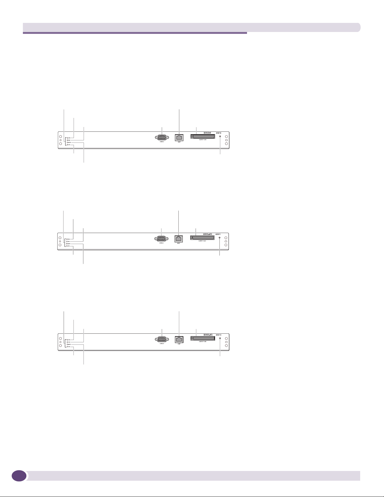
Figure 5 shows the MSM-5 module, Figure 6 shows the MSM-5R module, and Figure 7 shows the
MSM-6R module.
Figure 5: MSM-5 Module
Module status
LEDs
ERR
ENV
SYS Reset
MSTR
Figure 6: .MSM-5R Module
Module status
LEDs
ERR
ENV
SYS Reset
MSTR
MGMT port
Console
port
MGMT port
Console
port
Compact
flash
EX_150h
Compact
flash
EX_151h
Figure 7: .MSM-6R Module
Module status
LEDs
ERR
ENV
SYS Reset
MSTR
Each MSM consists of a printed circuit board mounted on a metal panel that acts as the insertion
vehicle in the BlackDiamond 12800 series switch. The module carrier also includes ejector/injector
levers and captive retaining screws at each end of the module front panel.
The MSMs have the following features on the front panel:
● Console port—The DB-9 serial console port is used to connect a terminal, allowing you to perform
local management.
● Management port—The 10/100 Mbps Ethernet management port allows you to connect an Ethernet
cable directly from your laptop to the management port to view and locally manage the switch
MGMT port
Console
port
Compact
flash
EX_183
22
BlackDiamond 12800 Series Switches Hardware Installation Guide

BlackDiamond 12800 Series I/O Modules
configurations. This port can also be used to connect the system to a parallel management network
for administration.
● Compact flash—You can insert an external compact flash memory card into this slot. (See Chapter 2
for more information about Extreme Networks-supported compact flash cards.)
● Reset button—Use the Reset button to reset the MSM without removing the module from the
chassis.
NOTE
Although the BlackDiamond 12800 series MSMs are similar in appearance, each MSM model has specific features.
The MSM-5R and MSM-6R modules belong to the R series and include the rate limiting feature, which the MSM-5
module does not support.
To use rate limiting, you must install modules with model numbers ending in R. These include the MSM-5R module
or MSM-6R module and the GM-20XTR I/O module, the XM-2XR I/O module, and the XM-2HR module.
The MSM-6R module provides the same functionality as the MSM-5R module, with higher performance
for CPU-based activities such as BGP, OSPF, and MPLS.
BlackDiamond 12800 Series I/O Modules
No configuration information is stored on the I/O modules; all configuration information is stored on
the MSMs.
When a BlackDiamond 12800 series switch is powered on, the software generates a default
configuration for any slots that contain I/O modules. The default configuration allows the I/O module
ports to participate in the VLAN named default. The default configuration for the I/O module is not
preserved unless you explicitly save the configuration to NVRAM.
You can configure parameters of an I/O module after it is installed, or preconfigure a slot for a certain
type of module and configuration. The preconfigured information is applied to the module after it is
inserted. If you preconfigure a slot for a specific module type and then insert a different type of
module, the module reverts to its default configuration.
NOTE
See the ExtremeXOS 12.0 Concepts Guide and the ExtremeXOS 12.0 Command Reference Guide for more
information about configuring the modules.
BlackDiamond 12800 Series Switches Hardware Installation Guide
23

BlackDiamond 12800 Series Modules
I/O Module LEDs
Tabl e 6 describes the LED activity for the BlackDiamond 12800 series I/O modules.
Table 6: BlackDiamond 12800 Series Switch I/O Module LEDs
LED Color Meaning
Status Green blinking Normal operation
Amber blinking Configuration error, hardware failure, diagnostic
failure, or other severe module error
Off No power
DIAG Off Normal operation
Amber blinking Diagnostics in progress
Amber Diagnostic failure
Port LEDs on I/O Modules
Tabl e 7 describes the LED activity for each port on the GM-20XT, GM-20XTR, XM-2X, XM-2XR, and
XM-2HR I/O modules.
Table 7: Port LEDs for the BlackDiamond GM-20XT, GM-20XTR, XM-2X, XM-2XR, and XM-2HR I/O
Modules
LED Color Meaning
Port Solid green Link up
Slow green blinking Port disabled
Amber blinking Activity
Off Link down
Tabl e 8 describes the LED activity for each port on the BlackDiamond GM-20T I/O module.
Table 8: Port LEDs for the BlackDiamond GM-20T Module
LED Color Meaning
Port with power enabled Solid amber Link up
Slow amber blinking Port disabled
Amber blinking Activity
Slow amber blinking Link down
Blinking amber/green Power fault or insufficient power
Port with power disabled Solid green Link up
Slow green blinking Port disabled
Green blinking Activity
Off Link down
Blinking amber/green Power fault or insufficient power
24
BlackDiamond 12800 Series Switches Hardware Installation Guide
GM-20T I/O Module
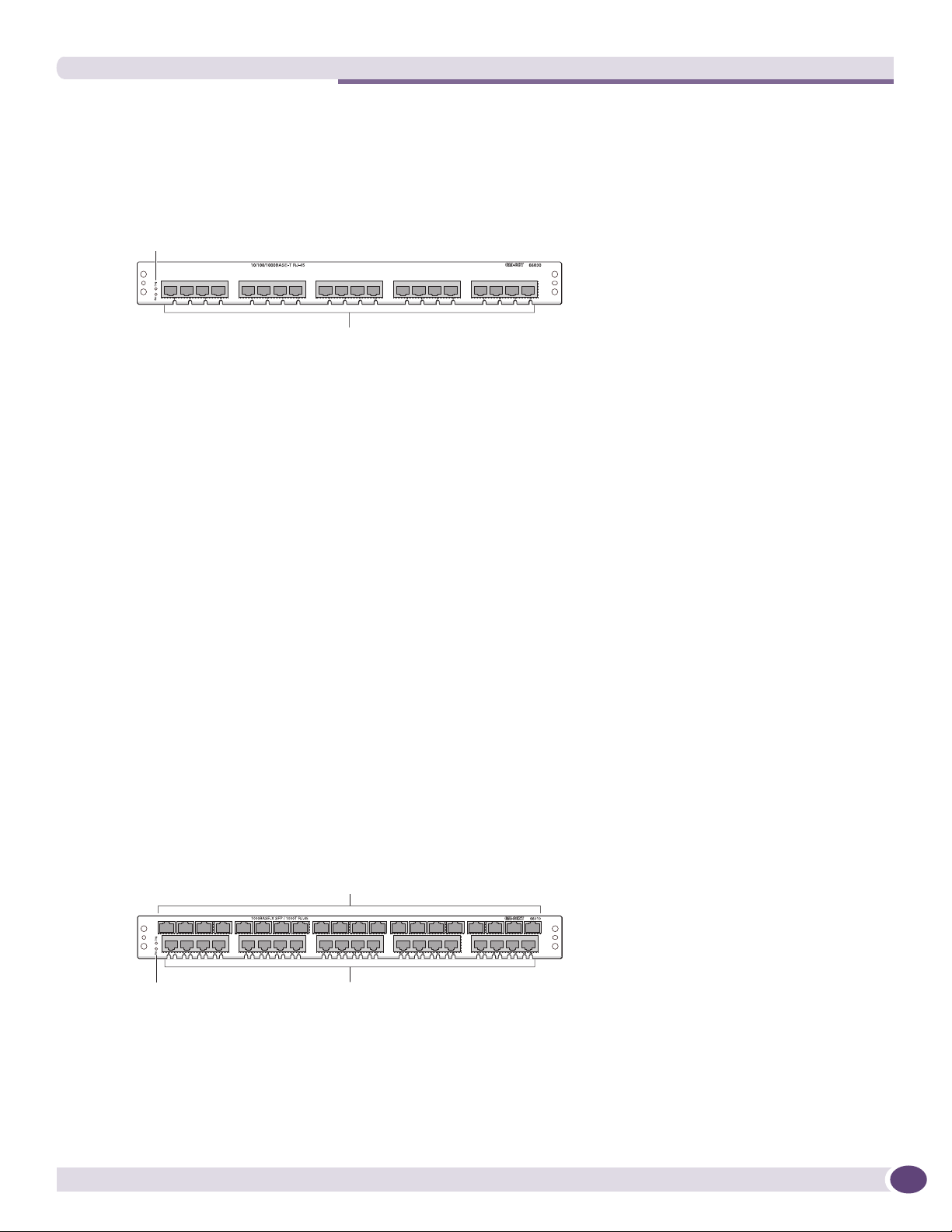
Figure 8 shows the GM-20T I/O module.
Figure 8: GM-20T I/O Module
Module status
LEDs
BlackDiamond 12800 Series I/O Modules
10/100/1000BASE-T
EX_152h
The GM-20T I/O module has 20 autosensing 10/100/1000BASE-T ports that use standard RJ-45
connectors.
The default configuration of the GM-20T I/O module is as follows. All ports:
● Are added to the default VLAN as untagged.
● Inherit the properties of the default VLAN (for example, protocol type and VLANid).
● Operate in autonegotiation mode.
GM-20T LEDs
The GM-20T I/O module has the following LEDs:
● Module status
● Module diagnostics
● Port status
● Power status
GM-20XT and GM-20XTR I/O Modules
Figure 9 shows the GM-20XT I/O module, and Figure 10 shows the GM-20XTR I/O module.
Figure 9: GM-20XT I/O Module
Mini-GBIC
fiber ports
Module status
LEDs
BlackDiamond 12800 Series Switches Hardware Installation Guide
10/100/1000BASE-T ports
EX_153h
25

BlackDiamond 12800 Series Modules
Figure 10: GM-20XTR I/O Module
Mini-GBIC
fiber ports
Module status
LEDs
10/100/1000BASE-T ports
EX_154h
NOTE
Although the GM-20XT module and the GM-20XTR module are similar in appearance, they have different
functionality. The GM-20XTR is part of the R series and includes the rate limiting feature; the GM-20XT module
does not support rate limiting.
To use rate limiting, you must install the MSM-5R plus the GM-20XTR I/O module and/or the XM-2XR I/O module.
The GM-20XT module and GM-20XTR I/O module have 20 autosensing 10/100/1000BASE-T ports that
use standard RJ-45 connectors and 20 SFP ports. Each pair of ports operates as a combination port.
Either the copper port or the fiber port can be active, but not both. You can set up a redundant link by
connecting both the copper and fiber ports in the pair. The port that is connected first becomes the
active port. If that port fails, the second port automatically becomes active. For more information about
redundant ports and automatic failover, see the ExtremeXOS Concepts Guide.
The default configuration of the GM-20XT and GM-20XTR I/O module is as follows. All ports:
● Are added to the default VLAN as untagged.
● Inherit the properties of the default VLAN (for example, protocol type and VLANid).
● Operate in autonegotiation mode.
26
GM-20XT and GM-20XTR LEDs
The GM-20XT and GM-20XTR I/O modules have the following LEDs:
● Module status
● Module diagnostics
● Port status
XM-2X and XM-2XR I/O Modules
Figure 11 shows the XM-2X I/O module, and Figure 12 shows the XM-2XR I/O module.
BlackDiamond 12800 Series Switches Hardware Installation Guide
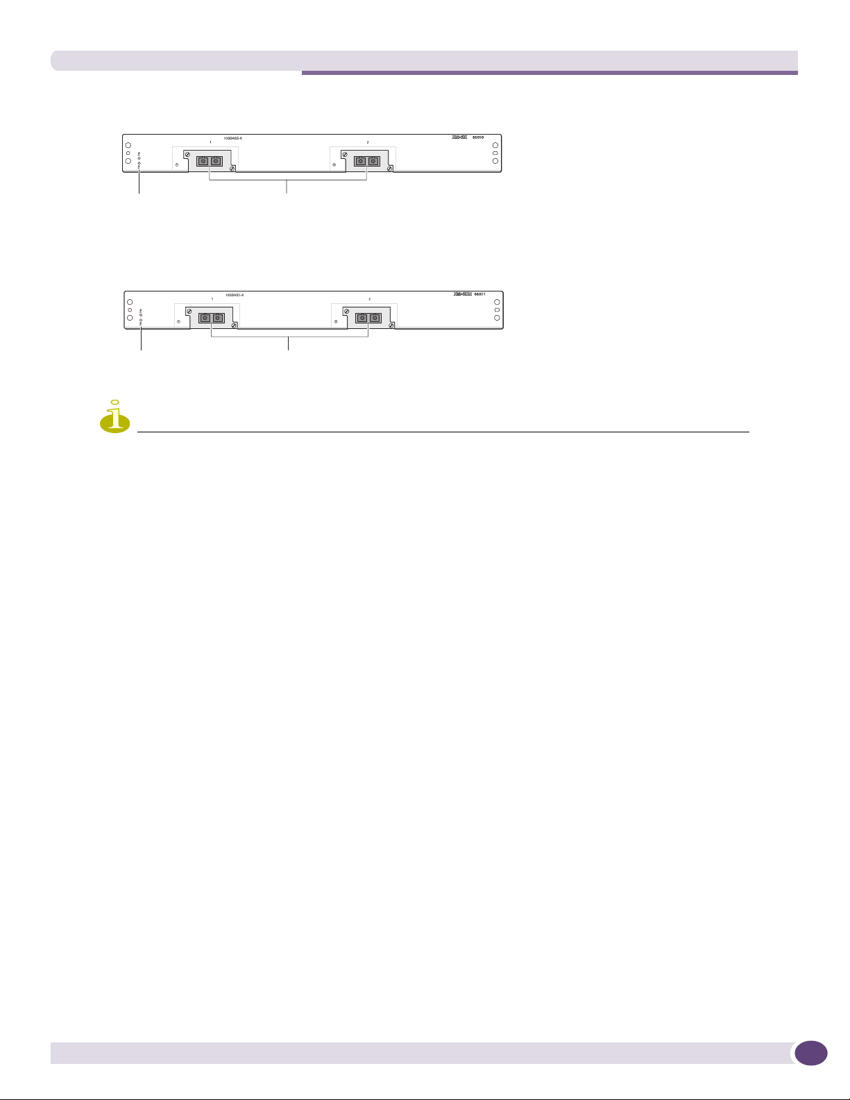
Figure 11: XM-2X I/O Module
BlackDiamond 12800 Series I/O Modules
Module status
LEDs
10 Gbs ports
EX_155h
Figure 12: XM-2XR I/O module
Module status
LEDs
NOTE
Although the XM-2X module and the XM-2XR module are similar in appearance, the functionality of each I/O module
varies. The XM-2XR module is part of the R series and includes the rate limiting feature; the XM-2X module does
not support rate limiting.
To use rate limiting, you must install the MSM-5R plus the GM-20XTR I/O module and/or the XM-2XR I/O module.
The XM-2X module and XM-2XR module have two unpopulated XENPAK-based 10 Gigabit Ethernet
ports.
The default configuration of the XM-2X and XM-2XR I/O modules is as follows. All ports:
● Are added to the default VLAN as untagged.
● Inherit the properties of the default VLAN (for example, protocol type and VLANid).
10 Gbs ports
EX_156h
XM-2X and XM-2XR LEDs
The XM-2X module and XM-2XR module have the following LEDs:
● Module status
● Module diagnostics
● Port status
BlackDiamond 12800 Series Switches Hardware Installation Guide
27
BlackDiamond 12800 Series Modules
XM-2HR I/O Module
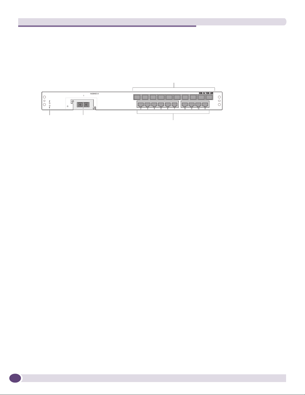
Figure 13 shows the XM-2HR I/O module.
Figure 13: XM-2HR I/O Module
Mini-GBIC
fiber ports
Module status
LEDs
10 Gbs ports
10/100/1000BASE-T ports
BD_167
The XM-2HR I/O module has 10 SFP ports and 10 autosensing 10/100/1000BASE-T ports that use
standard RJ-45 connectors. In addition, it has one unpopulated XENPAK-based 10-Gigabit Ethernet
port.
The default configuration of the XM-2HR I/O module is as follows. All ports:
● Are added to the default VLAN as untagged.
● Inherit the properties of the default VLAN (for example, protocol type and VLANid).
In addition, the 10/100/1000BASE-T ports and SFP ports operate in autonegotiation mode.
XM-2HR LEDs
The XM-2HR I/O module has the following LEDs:
● Module status
● Module diagnostics
● Port status
28
BlackDiamond 12800 Series Switches Hardware Installation Guide

3 Extreme Networks Power Supply Units for
BlackDiamond Switches
This chapter includes the following sections:
● Overview of BlackDiamond 12800 Series Power Supplies on page 29
● Extreme Networks 1200 W DC PSU on page 30
● Extreme Networks 700/1200 W AC PSU on page 32
● Extreme Networks 325 W DC Power Supply on page 34
● Extreme Networks 325 W AC Power Supply on page 36
NOTE
For central DC power connections, the 1200 W DC PSU and 325 W DC PSU are intended to be installed only in
restricted access locations (dedicated equipment rooms, equipment closets, or the like) in accordance with Articles
110-16, 110-17, and 110-18 of the National Electric Code, ANSI/NFPA-70. All wiring methods involving the DC
input cable assembly must be performed according to the relevant articles of the National Electrical Code.
WARNING!
Field operators must not attempt to open the PSU enclosure for any reason; the PSU does not contain
user-serviceable parts. In the event of failure, return the defective PSU to Extreme Networks for repair or
replacement.
Overview of BlackDiamond 12800 Series Power Supplies
The BlackDiamond 12800 series switches can be powered by either AC or DC power supplies (PSUs).
Power supplies in the BlackDiamond 12800 series switches are fully fault tolerant and load-sharing in
an N+1 configuration. After the system is properly configured, if one PSU fails, the others will provide
sufficient power to operate a fully loaded switch.
The BlackDiamond power supply units are intended for use in specific BlackDiamond switches only.
Tabl e 9 lists the power supplies for use in the BlackDiamond 12800 series switches.
Table 9: PSUs for the BlackDiamond 12800 Series Switches
BlackDiamond Switch Compatible PSU Compatibility Notes
BlackDiamond 12804 700W/ 1200W AC PSU
OR
1200W DC PSU
BlackDiamond 12802 325 W AC PSU, Model # 65021
OR
325 W DC PSU, Model # 65022
Extreme Networks does not recommended using
the 700/1200 W AC PSU in combination with a
1200W DC PSU.
Extreme Networks does not recommended using
the 325 W AC PSU in combination with the
325 W DC PSU.
BlackDiamond 12800 Series Switches Hardware Installation Guide
29
Extreme Networks Power Supply Units for BlackDiamond Switches
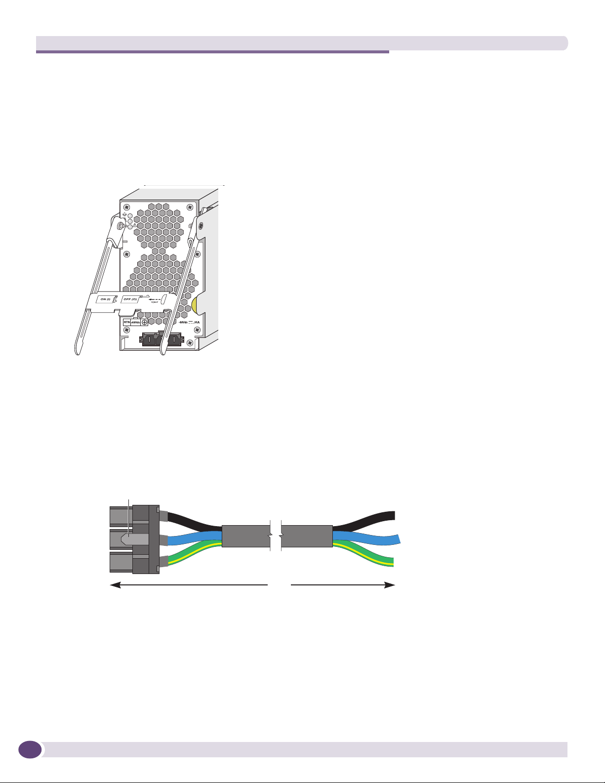
Extreme Networks 1200 W DC PSU
Figure 14 shows the Extreme Networks 1200 W DC UL-listed accessory power supply unit (Model
60021/PS 2350). This power supply is compatible with the BlackDiamond 12804 switch. The power
supply bay in the BlackDiamond 12804 switch can accommodate up to six hot-swappable Extreme
Networks 1200 W DC PSUs. You cannot install a 1200 W DC PSU in the BlackDiamond 12802 switch.
Figure 14: 1200 W DC PSU
BD_168
In an N+N configuration, each group of power supplies can provide A/B feed redundancy for the
system.
The input DC cable has an input connector on one end and precut wire on the other end that goes to
the DC power source (see Figure 15). The connector end has a locking mechanism that locks onto the
DC PSU to prevent accidental removal of the input DC cable.
Figure 15: Input DC Power Cable for the 1200 W DC PSU
Lock
Return
-48Vdc
Ground
10 ft.
Airflow enters from the front vents on the 1200 W DC PSU and exits to the rear vents of the switch.
Airflow through the 1200 W DC PSU is independent of the airflow through the rest of the switch.
To use the 1200 W DC PSU, you need a -48 V DC power source capable of providing 50 A dedicated
power to each of the 1200 W DC PSUs installed in the switch.
Black: Return
Blue: -48V
Green/yellow:
Ground
EX_135
30
BlackDiamond 12800 Series Switches Hardware Installation Guide
 Loading...