

Extreme Networks BlackDiamond 10K Series, BlackDiamond 10808 Installation Manual

Extreme Networks
BlackDiamond 10K-Series
Switch Installation Guide
Extreme Networks, Inc.
3585 Monroe Street
Santa Clara, California 95051
(888) 257-3000
http://www.extremenetworks.com
Part number: 104000-00 Rev. 02
Published: July 2004

©2003 Extreme Networks, Inc. All rights reserved. Extreme Networks, ExtremeWare, BlackDiamond, and Alpine are
registered trademarks of Extreme Networks, Inc. in the United States and certain other jurisdictions. ExtremeWare Vista,
ExtremeWorks, ExtremeAssist, ExtremeAssist1, ExtremeAssist2, PartnerAssist, Extreme Standby Router Protocol, ESRP,
SmartTraps, Summit, Summit1i, Su mmit4, Su mmit4/FX, Sum mit5i, Summ it7i, Summ it24, Summi t48, Summi t48i,
Summit Virtual Chassis, SummitLink, SummitGbX, SummitRPS and the Extreme Networks logo are trademarks of
Extreme Networks, Inc., which may be registered or pending registration in certain jurisdictions. The Extreme
Turbodrive logo is a service mark of Extreme Networks, which may be registered or pending registration in certain
jurisdictions. All other registered trademarks, trademarks and service marks are property of their respective owners.
Specifications are subject to change without notice.
All other registered trademarks, trademarks, and service marks are property of their respective owners.
For safety compliance information, see Appendix A.
Authors: Julie Laccabue
Production: Julie Laccabue
2

Contents
Preface
Introduction 7
Conventions 8
Related Publications 9
About This Guide 9
How To Use This Guide 10
Chapter 1 BlackDiamond 10808 Switch Overview
Summary of Features 11
Full-Duplex Support 12
Management Ports 12
Mini-GBIC Type and Hardware/Software Support 12
Mini-GBIC Types and Specifications 12
Safety Information 14
Preparing to Install or Replac e a Mini-GBIC 14
Installing and Re moving a Mini-GBI C 15
XENPAK Module Installation 16
Chapter 2 Site Preparation
Planning Your Site 20
Step 1: Meeting Site Requirements 20
Step 2: Evaluating and Meeting Cable Requirements 20
Step 3: Meeting Power Requirements 20
Meeting Site Requirements 20
Operating Environment Requirements 20
Rack Specifications and Recommendations 26
Evaluating and Meeting Cable Requirements 28
Cabling Standards 28
Extreme Networks BlackDiamond 10K-Series Switch Installation Guide 3

Cable Labeling and Record Keeping 28
Installing Cable 29
RJ-45 Connector Jackets 32
Radio Frequency Interference 32
Making Network Interface Cable Connections 33
Meeting Power Requirements 33
Power Supply Requirements 33
AC Power Cable Requirements 34
Uninterruptable Power Supply Requirements 35
Applicable Industry Standards 36
Chapter 3 BlackDiamond 10808 Switch Chassis
BlackDiamond 10808 Switch Architecture 37
BlackDiamond 10808 Switch Front View 37
BlackDiamond 10808 Switch Rear View 39
BlackDiamond 10808 Switch LEDs 40
Power Socket 40
Installing the Chassis 40
Standard Rack I nstallation 41
Mid-mount Rack Installation 49
Grounding the BlackDiamo nd 10808 Switch 51
Installing the BlackDiamond Cable Manager 52
Chapter 4 BlackDiamond 10808 Switch Management Module
MSM Activity 60
MSM LEDs 61
Installing MSMs 62
Verifying the MSM Installation 64
Removing MSMs 64
Chapter 5 BlackDiamond 10808 I/O Modules
Configuring I/O Modules 67
G60T Module 68
G60X Module 69
10G6X Modu le 70
I/O Module LEDs 71
Installing I/O Modules 72
Verifying the I/O Module Installation 74
LED Indicators 74
Displaying Slot Statu s Information 74
Removing I/O Modules 75
4 Extreme Networks Bla ckDiamond 10K-Ser ies Switch Installation Gui de

Installing a Blank Front Panel 76
Chapter 6 BlackDiamond 10808 Switch
Power Supplies and Power Supply Controllers
Power Supply Overview 80
Installing the Power Supplies 83
Removing the Power Supplies 84
Power Supply Controller Overview 85
Installing the Power Supply Controllers 86
Verifying a Successful Installation 86
Chapter 7 BlackDiamond 10808 Switch Fan Tray and Filter
BlackDiamond 10808 Switch Fan Tray 87
Removing the BlackDiamond 10808 Switch Fan Tray 88
Installing the Fan Tray 90
Replacing the Filter 91
Chapter 8 Initial Switch and Management Access
Connecting Equipment to the Console Port 93
Logging In fo r the First Time 95
Appendix A Safety Information
Important Saf ety Informa tion 97
Power 97
Power Cable 98
Connections 99
Lithium Battery 99
Appendix B Switch Technical Specifications
Index
Extreme Networks BlackDiamond 10K-Series Switch Installation Guide 5

6 Extreme Networks Bla ckDiamond 10K-Ser ies Switch Installation Gui de
Preface
This preface provides an overview of this guide, describes guide conventions, and lists other
publications that might be useful.
NOTE
To ensure prop er operation of your Extreme Network s equipment, read this gui de before you install any
Extreme Networks equi pment.
Introduction
This guide provides the required information to insta ll an Extreme Networks BlackDiamond® 10808
switch. It also contains info rmation about site locatio n, switch functionality, and switch operation.
This guide is intended for use by net work administrators who a re responsible for installing and setting
up network equipment. It assu mes a basic working knowledg e of:
• Local area networks (LANs)
• Ethern et conc epts
• Ethernet switching and bridging concepts
• Routing concepts
• Simple Network Management Protocol ( SNMP)
See the ExtremeWare XOS Concepts Guide and t he ExtremeWare XOS Comm and Reference Guide for
information about con figuring the BlackDiamon d 10808 switch.
NOTE
If the information in the re lease notes that shippe d with your switch differs from the information in thi s
guide, follow the release notes.
Extreme Networks BlackDiamond 10K-Series Switch Installation Guide 7

Preface
Conventions
Table 1 and Table 2 list conventions used throughout this guide.
Table 1: Notice icons
Icon Notice Type Alerts you to...
Note Important features or instructions.
Caution Risk of perso nal injury , system damage,
Warning Risk of severe pe rsonal injury .
or loss of dat a.
Table 2: Te xt c on v en ti on s
Convention Description
Screen displays This typeface represents information as it appears on the screen,
Screen displays bold This typeface represents commands that you type.
The words “enter”
and “type”
[Key] names Key names appear in text in one of two ways:
Words in italicized type Italics emphasize a point of information or denote new terms at the
or command syntax.
When you see the word “enter” in this guide, you must type
something, and then press the Return or Enter key. Do not press
the Return or En ter key when an instruct ion simply sa ys “type.”
• Referenced by their labels, such as “the Return key” or “the
Escape key”
• Written with brackets, such as [Return] or [Esc]
If you must press two or more keys simultaneously, the key names
are linked with a plus sign (+). Example:
Press [Ctrl]+[Alt]+[Del].
place where they are defined in the text.
8 Extreme Networks Bla ckDiamond 10K-Ser ies Switch Installation Gui de

Related Publications
Related Publications
The Extreme Networks switch documentation set includes:
• Extreme Networks BlackDiamond 10808 Installation Guide
• ExtremeWare XOS Concepts Guide
• ExtremeWare XOS Command Reference Guide
• ExtremeWare XOS Release Notes
Documentation for Extreme Networks products is available from the Extreme Networks website a t the
following location:
http://www.extremenetworks.com/services/documentation/
You can select and download the followin g Extreme Networks documentation from the Docum entation
section of the Services page:
• Release Notes (you must have a valid service contract to access the release notes)
• Software User Guides
• Hardware User Guides
• White Papers
• Troub leshooting Tools
• Preventative Maintenance
• Instructional Videos
• Archives
About This Guide
This guide describes how to prepare your site a nd how to install, maintain , and operate your Extreme
Networks switch.
• Site Planning—Describes how to evaluate, plan, and determine th e location of your Extreme
Networks switch.
• BlackDiamond Switch—Describes the features that a re specific to the BlackDiamond switch. This
section provides an overview of the BlackDia mond switch, information a bout model types, a
summary of features, and insta llation guidelines.
• Switch Operation—Describes how to pow er on any Extreme Networks switch, verify the swi tch
installation, connect equipment to the con sole port, and log in to the switch for th e first time.
• Appendixes—Includes informatio n about safety requirements and technica l specifications.
Extreme Networks BlackDiamond 10K-Series Switch Installation Guide 9

Preface
How To Use This Guide
Each chapter of this guid e contains information on how to successful ly operate your Ext reme Networks
BlackDiamond 10808 switch.
This guide also contains appendices that describe:
• Switch safety issues
• Switch specifications
• Module specifications
Appendix A, “Safety Information” describes important safety issues such as power, power cables, and
fuses.
Appendix B, “Switch Technical Specifications” describes switch specifications such as physical
dimensions, weight, certifications, and po wer supply parameters.
Appendix C, “Module Technical Specifications” describes module specification s such as physical
dimensions, weight, and standards.
Information that is comm on to all modules is described at t he end of the appendix.
10 Extreme Networks BlackDiamond 10K -Series Switch Installation Guide

1 BlackDiamond 10808 Switch Overview
The BlackDiamond 10808 swit ch is a chassis-based, Ethernet service co re switch designed for core
applications.
This chapter describes:
• Summary of Features on page 11
• Full-Duplex Support on page 12
• Management Ports on page 12
• Mini-GBIC Type and Hardware/Software Support on page 12
• XENPAK Module Installation o n page 16
Summary of Features
This section describes the features of the Black Diamond 10808 switch. If the inf ormation in the release
notes differs from the information in this g uide, follow the release notes. For more info rmation about
configuring the switch, refer to the ExtremeWare XOS Concepts Guide an d the ExtremeWare XOS Command
Reference Guide.
The features of the BlackDiamond 10808 switch include:
• A 10-slot chassis that can be populated with up to eight input/output (I/O) modul es and two
Management Switch Fabric Modules (MSM-1 and MSM-1XL)
• I/O modules that are hot-swappable, and include Gigabit Ethernet copper ports (10/100/1000) and
Gigabit Ethernet fiber ports (SFP), or 10 Gigabit Ethernet ports
• Redundant, load-sharing, hot-swappable power supplies
• Field-replaceable, hot-swappable fan trays
• Autonegotiation for half-duplex o r full-duplex operation on 10/100/1000 Mbps ports
• Load-sharing on multiple po rts
Extreme Networks BlackDiamond 10K-Series Switch Installation Guide 11

BlackDiamond 10808 Switc h Overview
Full-Duplex Suppor t
Extreme Networks switches provide full-duplex support for all ports. This m eans that frames can be
transmitted and received simultaneously, which, in effect, doubles the bandwidth available on a link.
Most ports on an Extreme Networks switch au tonegotiate for half- duplex or full-duplex operation.
Gigabit Ethernet fiber ports and 10 G igabit Ethernet ports operate in f ull-duplex mode only in
accordance with technical standards.
Management Por ts
The 10/100BASE-TX Ethernet managem ent port allows you to communica te directly to the CPU of the
switch. You can plug an Ethernet cable directly from your lapto p into the management po rt, which
provides you with direct access into the switch. This acces s allows you to view and locall y manage the
switch configurations.
Do not assign an in-band IP address to the management port VLAN. The management port VLAN is an
out-of-band VLAN, so if it is assigned an in-band IP address (an address where the source and
destination are in the same subnet), the switch will treat it as a normal VLAN and attempt to route
traffic through it.
The management port is located on the f ollowing Extreme Networks devices:
• BlackDiamond—Manag ement Switch Fabric Module (MSM-1 and MSM-1XL)
— The MSM-1XL has 256,000 entries in its lookup tables versus 128,000 entries in the MSM-1. The
MSM-1XL is necessary to support BGP-4.
Extreme Networks does not recommend that you use the manageme nt port to route traffic to any front
panel port on the switch. The managemen t port is designed for switch managem ent purposes.
Mini-GBIC Type and Hardware/Software Suppor t
The BlackDiamond 10808 switch supports the small form plugga ble (SFP) GBIC, also known as th e
mini-GBIC. The switches and the modules identify the type of mini-GBIC that is installed and verifies
that the mini-GBIC is an Extreme Networks-certified mini-GBIC.
Mini-GBIC Types and Specifications
The three types of mini-GBIC interfaces are:
• SX mini-GBIC , which confo rms to the 1000 BASE-SX sta ndard
• LX mini-GBIC, which conforms to the 1000BASE-LX standard
• ZX mini-GBIC, which conforms to the IEEE 802.3z standard
Use only Extreme Networks-certified mini-GBICs, available from Extreme Networks, into the
mini-GBIC port in the switch or module.
12 Extreme Networks BlackDiamond 10K -Series Switch Installation Guide

Mini-GBIC Type and Hardware/Software Support
Table 3 describes the specifications for the SX mini-GBIC in terface, Table 4 describes the specifications
for the LX mini-GBIC interface, and Table 5 describes the specifications for the ZX mini-GBIC interface.
Table 3: SX mini-GBIC specifications
Parameter Minimum Typical Maximum
Transceiver
Optical output power -9.5 dBm -4 dBm
Center wavelength 830 nm 850 nm 860 nm
Receiver
Optical input power sensitivity -21 dBm
Optical input power maximum -4 dBm
Operating wavelength 830 nm 860 nm
General
Total system budget 11.5 dB
Total optical system budget for the SX mini-GBIC is 11.5 dB. Extreme Networks recommends that 3 dB
of the total budget be reserved for losses induced by cable splices/connectors and operating margin.
While 8.5 dB remains available for cable induced attenuation, the 1000BASE-SX standard specifies
supported distances of 275 meters over 62.5 micron multimode fiber and 550 meters over 50 micron
multimode fiber. There is no minimum attenua tion or minimum cable length restriction.
Table 4: LX mini-GBIC s pecifications
Parameter Minimum Typical Maximum
Transceiver
Optical output power -9.5 dBm -3 dBm
Center wavelength 1275 nm 1310 nm 1355 nm
Receiver
Optical input power sensitivity -23 dBm
Optical input power maximum -3 dBm
Operating wavelength 1270 nm 1355 nm
General
Total system budget 13.5 dB
Total optical system budget for the LX mini-GBIC is 13.5 dB. Measure cable plant losses with a 1310 nm
light source and verify this to be within budget. When you calcul ate the maximum distance attainable
using optical cable with a specified loss per kilometer ( for example 0.25 dB/km), Extreme Networks
recommends that 3 dBm of the total budget be reserved for losses induced by cable splices/connectors
and operating margin. Thus, 10.5 dB remains available for cable induced attenuatio n. There is no
minimum system budget or minimum cable length restriction because the maximum receive power is
the same as the maximum transmit power. There is no minimum attenuation or minimum cable length
restriction.
Extreme Networks BlackDiamond 10K-Series Switch Installation Guide 13

BlackDiamond 10808 Switc h Overview
Table 5: ZX mini-GBIC sp ecifications
Parameter Minimum Typical Maximum
Transceiver
Optical output power -2 dBm 0 dBm 3 dBm
Center wavelength 1540 nm 1550 nm 1570 nm
Receiver
Optical input power sensitivity -23 dBm
Optical input power maximum -3 dBm
Operating wavelength 1540 nm 1550 nm 1570 nm
Safety Information
Before you begin the process of installing or replaci ng a mini-GBIC, read the safety inf ormation in this
section.
CAUTION
Mini-GBICs can emit invisible laser radiation. Avoid direct eye exposure to beam.
Mini-GBICs are Class 1 laser devices, and they operate at 3.3 V. Use only Extreme Networks-certified
mini-GBI C device s.
If you see an amber blinking mini-GBIC port status LED after you install a mini-GBIC into a
BlackDiamond 10K-series module, this means the mini-GBIC is not certified by Extreme Networks. To
correct this problem, install an Extreme Networks-certified mini-GBIC, available from Extreme
Networks, into the mini-GBIC port.
If you install a mini-GBIC n ot certified by Extreme Networks into a Black Diamond 10K-series module
and insert a cable to bring up the lin k, the port status L ED remains “off” and an error specifying the use
of a non-Extreme Networks-certified mini-GBIC is sent to the sysl og. To view the syslog and to
determine why the link is down , use the
show log command. To correct this problem, install an
Extreme Networks-certified mini-GBIC, available from Extreme Networks, into the mini-GBIC slot in
the module.
Preparing to Install or Replace a Mini-GBIC
To ensu re proper installation, complete the following five tasks before inserting the mini-GBIC:
1 Disable the port that is needed to install or replace the mini-GBIC.
2 Inspect and clean the fiber tips, coupler, and connectors.
3 Prepare and clean an external attenuator, if needed.
4 Do not stretch the fiber.
5 Make sure the bend radius of the fiber is not less than 2 inches (5.08 cm).
14 Extreme Networks BlackDiamond 10K -Series Switch Installation Guide
Mini-GBIC Type and Hardware/Software Support
In addition to the previously described tasks, Extreme Networks recommends the following when
installing or replacing mini- GBICs on an active netwo rk:
• Use the same type of mini-GBIC at each end of the link.
• Connect one end of the link to the Tx port. Without an attenuator, measure the total loss from the Tx
port to the other site of the link. The total loss must not exceed the total optical system budget.
After you complete these described tasks, you are ready to install or replace a min i-GBIC.
Installing and Removing a Mini-GBIC
You can add mini-GBICs into, or remove mini-GBICs from your BlackDiamond 10808 switch without
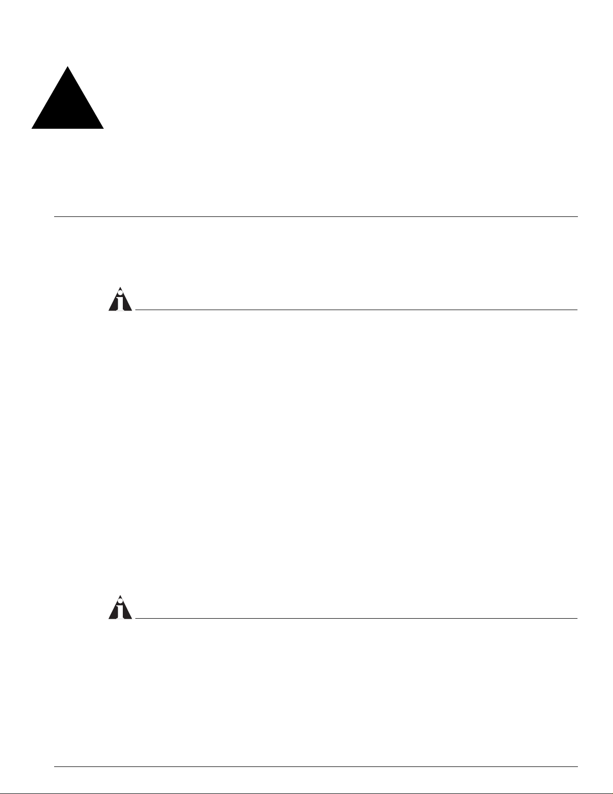
powering off the system. Figure 1 shows the two types o f mini-GBIC connectors.
Figure 1: Mini-GBIC modules
Module A Module B
XM_024
Mini-GBICs are a 3.3 V Class 1 laser devices. Use only Extreme-approved devices.
CAUTION
Mini-GBICs can emi t invisible laser radiation. Avoid direct eye exposure to beam.
NOTE
Remove the LC fiber-optic connector fr om the mini-GBIC pri or to removing the mini-GBIC fr om the
switch.
If you see an amber blinking mini-GBIC po rt status LED, the mini-GBIC insta lled in your switch or
module is not approved, supported, or certified by Extreme Networ ks. To correct this problem, install
an Extreme Networks-certified mini-GBIC.
To remove a m ini-GBIC similar to the one labeled “M odule A” in Figure 1, gently press and hold dow n
the black plastic tab at the bottom of the conn ector to release the mini-GBIC, and pull the mini-GBIC
out of the SFP receptacle .
Extreme Networks BlackDiamond 10K-Series Switch Installation Guide 15
BlackDiamond 10808 Switc h Overview
To remove a min i-GBIC connector similar to the on e labeled “Module B” in Figure 1, gently rotate the
front handle and pull the mini-GBIC out of the SFP receptacle.
To insert a mini-GBIC connector:
NOTE
Mini-GBICs can be ins talled in the SFP mini -GBIC receptacles onl y.
1 Holding the mini-GBIC by its sides, insert the m ini-GBIC into the SFP receptacle on the switch or
module.
2 Slide the mini-GBIC into the S FP receptacle until you h ear an au dible click, indicating th e mini-GBIC
is securely seated into the SFP receptacle. If the mini-GBIC ha s a handle, push up on the hand le to
secure the mini-GBIC.
XENPAK Module Installation
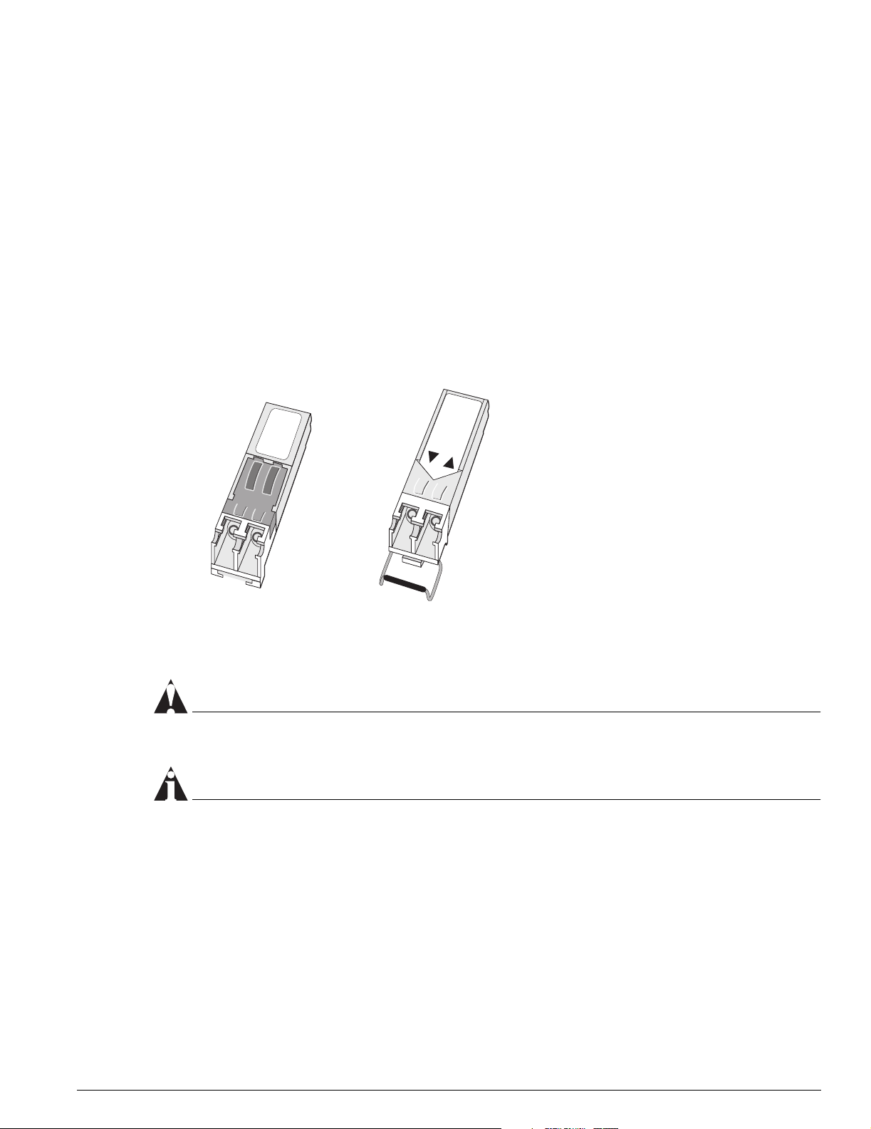
This section describes installi ng and removing the XENPAK module, a 10 Gbps optical transceiver. You
can install or remove the XENPAK module from your Extreme Networks switch without pow ering off
the system. The module is shown in Figure 2.
Figure 2: XENPAK module
Card edge
connector
EWUG003B
The XENPAK module is a Class 1 laser device. Use only Extreme-approved devices on all Extreme
switches.
CAUTION
The XENPAK mo dule can emit invisible laser radiation. Avoid direct eye exposure to beam.
WARNING!
To prevent ESD damage t o the XE NPAK module, always use an appropr iate ly grounded ESD-preventive
wrist strap when in stalling or removing t he module. Han dle the mo dule by its sides on ly. Never touch the
card-edge conne ctors at the inser tion end of the m odule.
16 Extreme Networks BlackDiamond 10K -Series Switch Installation Guide
XENPAK Module Installation
To install a XENPAK module:
1 Remove the XENPAK module from its antistatic container and remove the dust covers from the
module optical connectors. If your module has a protective pad covering the card-edge connector,
remove it. Store the antistatic container, dust covers, and card-edge connector protective pad in a
clean location from which they can be easi ly retrieved if you need to uninstall the module.
2 Remove any dust covers from the port on the module into which you are installing the XENPAK.
3 Holding the module by its sides, in sert it into the slot on the I/ O module.
4 Slide the module as far back into the slo t as possible, until you hear it cl ick, indicating that it is
firmly attached.
5 Secure the module to the I/O module faceplate by turning the t wo captive screws clockwise until
they are hand-tight.
NOTE
To ensure that your module is undamaged upon installation, you can c orrelate factory test da ta with
your installation site test data by consu lting the average power reference values shown on the XENPAL
module test data sheet (Par t No. 121074-00) enclosed with your module.
To remove a XENPAK module:
1 Turn th e two captive screws counter-clockwise until they are completely free from the I/O module
faceplate. (The captive screws remain attached to the XENPAK module.)
WARNING!
Remove the SC fiber-optic connector from the XENPAK m odule prior to rem oving the XENPAK
module from the I/O module.
2 Gripping both captive screws, gently pull the XE NPAK Module out of the slot.
3 Place the dust covers back into the XENPAK Module connectors.
4 Place the XENPAK module immediately into an antistatic contain er to protect it from ESD damage
and dust.
Extreme Networks BlackDiamond 10K-Series Switch Installation Guide 17

BlackDiamond 10808 Switc h Overview
18 Extreme Networks BlackDiamond 10K -Series Switch Installation Guide

2 Site Preparation
This chapter describes how to prepare your site for installing Extreme Networks equipment. It contains
information on environmental and cablin g requirements, power requirements, and building and
electrical code organizations.
This chapter describes:
• Planning Your Site on page 20
• Meeting Site Requirements on page 20
• Evaluating and Meeting Cable Requirements on page 28
• Meeting Power Requirements on page 33
• Applicable Industry Standards on page 36
The requirements described in this chapter are intended for the system administrator, network
equipment technician, or network manager who is responsible for installing and managing the network
hardware. It assumes a working kn owledge of local area networ k (LAN) operations, and a familiarity
with communications protocols that are used on interconnected LANs. Installation, maintenance, and
removal of a switch, chassis, or its compon ents must be done by qualified service perso nnel only.
Qualified service p ersonnel have had appropriate technica l training and ex perience that is n ecessary to
be aware of the hazards to which they are exposed when performing a task and of measures to
minimize the danger to themselves or other people.
By carefully planning your site, you can maximize the performa nce of your existing netwo rk and ensure
that it is ready to migrate to fut ure networking technologies.
To learn more about safety issues and to ensure safety compliance, see AppendixA.
WARNING!
Read the safety information in A ppendix A th oroughly before installing your Extreme Networks switch.
Failure to follow this safety information can lead to personal injur y or damage to th e equipment.
Extreme Networks BlackDiamond 10K-Series Switch Installation Guide 19

Site Preparation
Planning Your Site
To install your equipment su ccessfully, you should plan your site carefully. The site planning process
has three major steps:
Step 1: Meeting Site Requirements
Your ph ysical installation site must meet several requirements fo r a safe and successful insta llation:
• Building and electrical code requirements
• Environmental, safety, and thermal requirements for the equipment you plan to install
• Distribution rack requirements
Step 2: Evaluating and Meeting Cable Requirements
After examining your physical site and ensurin g all environment requirements are met, you should
evaluate and compare your existing cable plant with the requirements of the Extreme Networks
equipment to determine if you need to install new cables (or cablin g).
Step 3: Meeting Power Requirements
To run your equipment sa fely, you must meet the specific power requirements for the Extreme
Networks equipment that you pla n to install.
NOTE
Review and follow the safety information before you install your equipment.
Meeting Site Requirements
This section addresses the various requirements to consider when preparing your installation site,
including:
• Operating Environment Requirements
• Rack Specifications and Recommendations
Operating Environment Requirements
You need to verify t hat your site meets all environmental and safety requirements.
Virtually all areas of the United States are regulated by building codes and standards. During the early
planning stages of instal ling or modifying you r LAN, it is important that y ou develop a thorough
understanding of the regulations that pertain to y our location and industry.
20 Extreme Networks BlackDiamond 10K -Series Switch Installation Guide

Meeting Site Requ irements
Building and Electrical Codes
Building and electrical code s vary depending on your location . Comply with all code s pecifications
when planning your site and installing cable. The followin g sections are provided as a resource to
obtain additional information.
Three major building codes are:
• Uniform Building Code—produced by the International Conference of Building Officials (ICBO);
5360 South Workman Mill Road; Whittier, California 90601 USA. www.icbo.org
• BOCA Basic Building Code—produced by the Building Officials and Code Administrators (BOCA)
International, Inc.; 4051 West Flossmoor Road; Country Club Hills, Illin ois 60478 USA.
www.bocai.org
• Standard Building Code (SBC)—produced by the Southern Building Code Congress International,
Inc.; 900 Montclair Road; Birmingham, Alabama 35213 USA. www.sbcci.org
Five authorities on electrical codes are:
• National Electrical Code (NEC) Classifica tion (USA only)—a recognized authori ty on safe electrical
wiring. Federal, state, and lo cal governments use NEC sta ndards to establish their own la ws,
ordinances, and codes on wiring specifica tions. The NEC classification is published by the National
Fire Protection Association (NFPA). The address is NFPA; 1 Batterymarch Park; Quincy,
Massachusetts 02269 USA. www.nfpa.org
• Underwriters’ Laboratory (UL) (USA only)—an independent research and testing laboratory. UL
evaluates the performance and capability of electrical wiring and equipment to determine whether
they meet certain safety standards when properly used. Acceptance is usually indicated by the
words “UL Approved” or “UL Listed.” The address is UL; 333 Pfingsten Road; Northbrook, Illinois
60062-2096 USA. www.ul.com
• National Electrical Manufacturing A ssociation (NEMA) (US A only)—an organization of elect rical
product manufacturers. Members develop consensus standards for cables, wiring, and electrical
components. The address is NEMA; 2101 L Street N.W.; Washington, D.C. 20037 USA.
www.nema.org
• Electronics Industry Association (EIA)—a trade association that develops technical standards,
disseminates marketing data, an d maintains contact with governme nt agencies in matters relating to
the electronics industry. The address is EIA; 2001 Eye Street N.W.; Washington, D.C. 20006 USA.
www.eia.org
• Federal Communications C ommission (FCC)—a commissi on that regulates all interstate and foreign
electrical communication systems t hat originate in the United Stat es according to the
Communications Act of 1934. The FCC regulates all U.S. telephone and cable systems. The address is
FCC; 1919 M Street N.W.; Washington, D.C. 20554 USA.
Extreme Networks BlackDiamond 10K-Series Switch Installation Guide 21

Site Preparation
Wiring Closet Considerations
You sho uld consider the following recommendations for your wiring closet:
• Ensure that your system is easily accessible for instal lation and service. See “Rack Specifica tions and
Recommendations” on pa ge 26 for specific recommendat ions.
• Use appropriate AC power for your switch , as describ ed in Table 6.
Table 6: AC power requirements
Country Requirements
North America 13 A service receptacle, NEMA 5-15 for 110/220 VAC power supplies.
United Kingdom 10 A service receptacle, BS 1363 for 110/220 VAC power supplies.
International 10 A service receptacle, CEE 7/7 for 110/220 VAC power supplies.
Australia 10 A service receptacle, AS 3112 for 110/220 VAC power supplies.
Japan 15 A service receptacle, JIS 8303 for 110/220 VAC power supplies.
• Use a vinyl floor covering in your wiring closet. (Concrete floors accumulate dust, and carpets can
cause static electricity.)
• Prevent unauthorized access to wiring closets by providing door locks. Install the equipment in a
secured, enclosed, and restricted-access area, ensuring that only qualified service personnel have
access to the equipment.
• Provide adequate overhead lighting for easy maintena nce.
• Ensure that each wiring closet has a suita ble ground. All distribution racks and equipment installed
in the closet should be grounded.
• Ensure that all system environmental requirements are met, such as ambient temperature and
humidity.
NOTE
Extreme Networks recom mends that you consult an electr ical contractor for commercial buildi ng and
wiring specific ations.
Temperature. Extreme Networks equipment generates a significant am ount of heat. It is essenti al that
you provide a temperature-controlled environment for both performance and safety.
Install the equipment only i n a temp erature- and humidity -controlled indoor area that i s free of airborne
materials that can conduct electricity. Too much humidity can cause a fire. Too little humidity can
produce electrical shock and fire.
The following are some general thermal recommen dations for your wiring clos et:
• Ensure that the ventilation in the wirin g closet is adequate to maintain a temperature below 104° F
(40° C).
• Install a reliable air conditioning and ventilation sys tem.
• Keep the ventilation in the wiring closet running during nonbusiness hours; othe rwise, the
equipment can overheat.
22 Extreme Networks BlackDiamond 10K -Series Switch Installation Guide

Meeting Site Requ irements
• Maintain ambient operating temperature: 32° to 104° F (0° to 40° C).
• Maintain storage temperature: -40° to 158° F (-40° to 70° C).
NOTE
Like all electrical equ ipment, product lifetimes d egrade with increased temperature. If pos sible,
temperatures should be kept at approximately 78° F (25° C) or lower.
Spacing Requirements. Due to chassis-to-chassis heating, Extreme Networks recommends placing no
more than three BlackDiamond 10808 chassis next to each other.
The following are some general recommendati ons for installing your B lackDiamond 1080 8 switch:
• A minimum of 17.32 inches (44 cm)
between each set of three BlackDiamond 10808 switch.
Or
• Place patch panels, which are used to patch cables together, between each set of three BlackDiamond
BlackDiamond 10808 switches. A patch panel does not require any power and does n ot generate any
heat.
NOTE
Up to five adjacent BlackDiamond 10808 switches will continue to function without safety concerns.
However, produ ct lifetime may degrade with continued exposure to high tempe ratures in close proximity
and long term reliability may be compro mised.
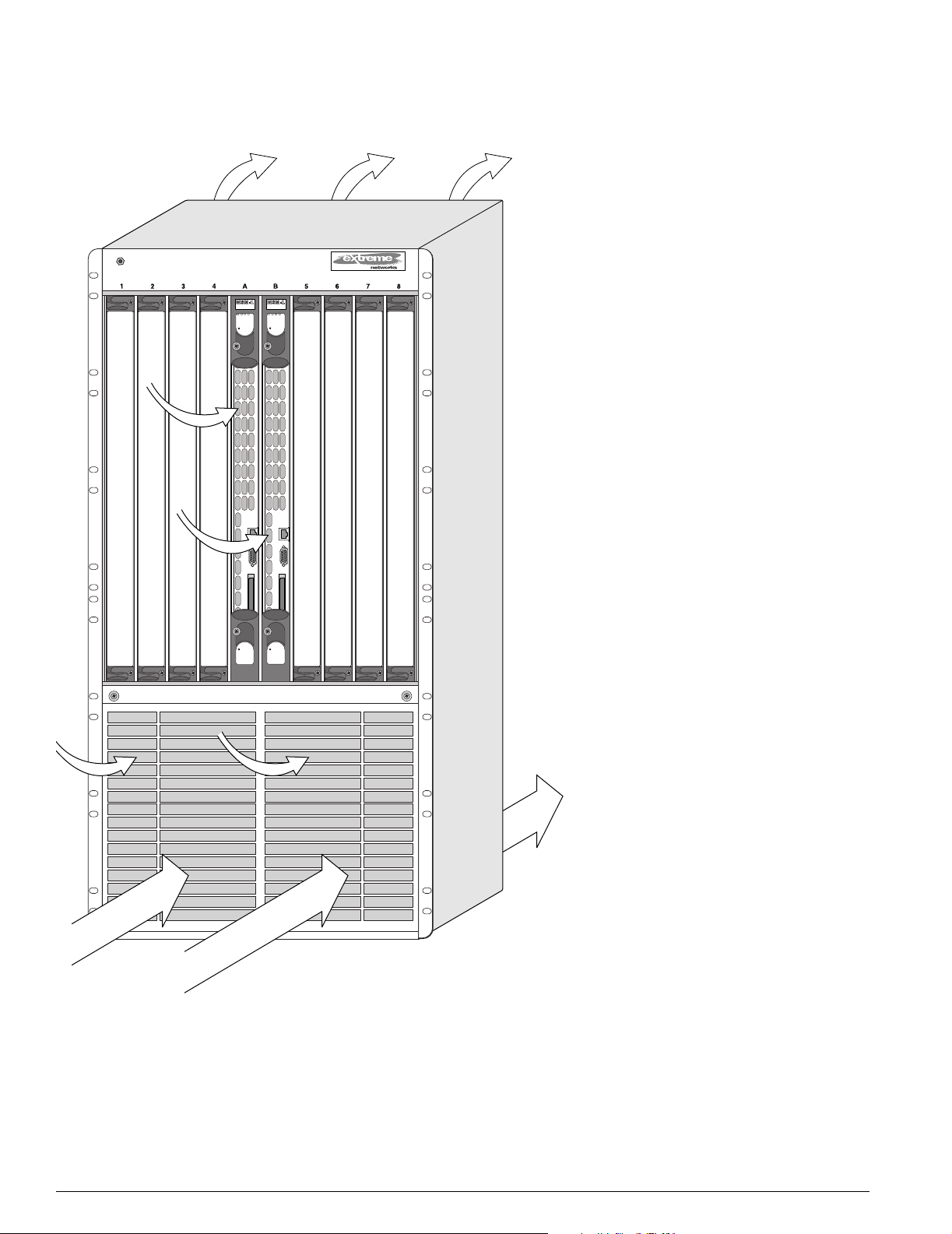
Airflow Requirements. To ensure proper airflow through an Extreme Networks switch, refer to the
following recommendations wh en you are installing your swi tch:
• The BlackDiamond 10808 switch requires 3 inches (7.62 cm) around both the front and rear of the
chassis (5 inches (12.7 cm) recommended) for proper airflow.
The airflow of the BlackDiamon d 10808 switch moves through t he power supplies and is independent
of the airflow through the modules as shown in Figure 3. For example, if the power supp ly fans fail, the
airflow through the module area of the chassis will no t cool down the power supplies.
• Airflow for cooling power supp lies moves front to back as you face the chas sis.
• Airflow for cooling modules moves left to right as you face the cha ssis.
Extreme Networks BlackDiamond 10K-Series Switch Installation Guide 23
Site Preparation
Figure 3: Airflow through the Bl ackDiamond 10808 switch chassis
Airflow through
power supplies
EX_010
Humidity. Operating humidity should be kept between 10 and 95% relative humidity (noncondensing).
24 Extreme Networks BlackDiamond 10K -Series Switch Installation Guide
Meeting Site Requ irements
Electrostatic Discharge (ESD)
Your system mu st be protected from static electricity. Take the following measures to ensure optimum
system performance:
• Keep relative humidity at 50 to 70%.
• Remove materials that can cause electrostatic generation (such a s synthetic resins) from the wiring
closet. Check the appropriateness of floor mats and flooring.
• Connect conductors (metals, etc.) to ground , using dedicated grounding lines.
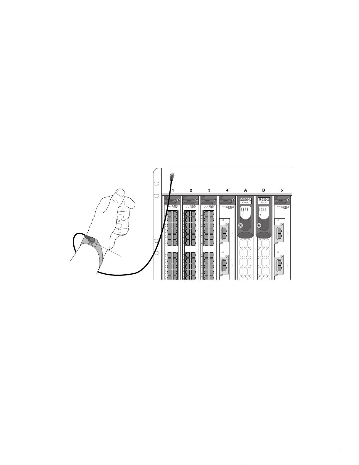
• Use electrostatically safe equipment and the ESD straps that are provided with your equipment. All
BlackDiamond switches come with ESD wrist strap connectors and wr ist straps as shown in
Figure 4.
Figure 4: Ensure that you use an ESD wr ist strap when handling switch com ponents
ESD ground
connection
ESD strap
EX_013
Extreme Networks BlackDiamond 10K-Series Switch Installation Guide 25

Site Preparation
Rack Specifications and Recommendations
Racks should conform to conventional standards. In the United States, use EIA Standard RS-310C:
Racks, Panels, and Associated Equipment. In countries other than the United States, use IEC Standard
297. In addition, verify that your rack meets the basic mechanical and space requirements that are
described in this section.
Mechanical Recommendations for the Rack
Use distribution racks that meet the foll owing mechanical recommendat ions:
• Use an open style, 19-inch (48.26 cm) rack to facilitate easy maintenance and to provide proper
ventilation.
• The rack should use the universal mo unting rail hole pattern th at is identified in IEC Stan dard 297.
• The mounting holes should be flush with the rails to accommodate the chassis.
• Use a rack made of steel or aluminum.
• Install equipment into the lower half of the rack f irst to avoid making the rack top-heavy.
• The rack should support approximately 600 pounds (272 kilograms).
Protective Grounding for the Rack
Use a rack grounding kit and a ground conductor th at is carried back to earth or to a nother suitable
building ground.
All Extreme Networks switches are designed with mounting brack ets that provide solid metal-to-metal
connection to the rack. If you do not use equipment racks, y ou can attach wiring terminals directly to
the mounting brackets for appropriate grounding. Blac kDiamond products have grounding terminals
that are mounted on the back of the chassis.
At minimum, follow these guidelines:
• Ground equipment racks to earth ground.
— CAD weld appropriate wire terminals to building I- beams or earth ground rods.
— Use #4 copper wire.
— Drill and tap wire terminals to equipment racks.
— Position the earth ground as close to the equipment rack as possible to maintain the shortest
wiring distance possible.
— Properly test the quality of the earth ground.
NOTE
Because building codes vary wor ldwide, Extre me Networ ks strong ly recomm ends t hat you consult an
electrical con tractor to ensure proper equ ipment grounding is in place for your specific installa tion.
• Ground DC power supplies to earth ground by using th e grounding terminals provided.
26 Extreme Networks BlackDiamond 10K -Series Switch Installation Guide
Meeting Site Requ irements
Space Requirements for the Rack
Provide enough space in front of and behind the sw itch so that you can service it easi ly. Allow a
minimum of 48 inches (122 cm) in front of the rack and 24 inches (61 cm) behind the rack. When using a
relay rack, provide a minimum of 24 inches (61 cm) of space behind the mounted equipment. Extra
room on each side is opti onal.
NOTE
Install your equipment rack near an eas ily accessible power outlet. When you need to d isconnect the
power cable from your switch, remove it first from the power source and th en from the switch.
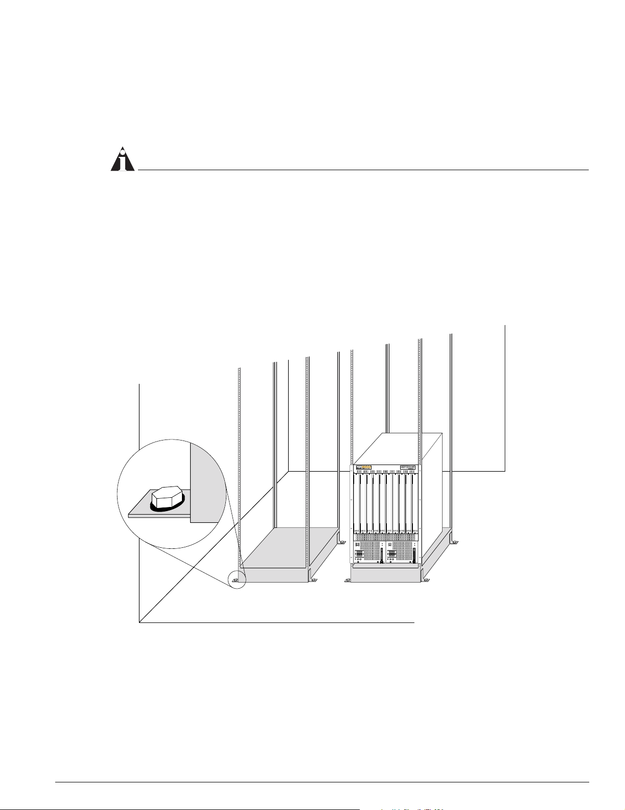
Securing the Rack
The rack should be attached to the wiring closet floor with 3/8 inch (9.5 mm) lag screws or equivalent
hardware. The floor under the rack should be level with in 3/16 inch (5 mm) . Use a floor-leveling
cement compound if necessary or bo lt the racks to the floor as sh own in Figure 5.
Figure 5: Properly secur ed rack
Secure to floor
with 3/8 inch lag screws or bolts
SPG_007
Brace open distribution racks if the ch annel thickness is less than 1/4 inch (6.4 mm).
Extreme Networks BlackDiamond 10K-Series Switch Installation Guide 27

Site Preparation
Evaluating and Meeting Cable Requirements
This section addresses requirements for the cable you should use when installing you r network
equipment. It includes:
• Cabling Standards
• Cable Labeling and Record Keeping
• Installing Cable
• RJ-45 Connector Jackets
• Radio Frequency Interference
Cabling Standards
Extreme Networks recommends using the BICSI (Building In dustry Consulting Service Internatio nal)
RCDD (Registered Communications Distribution Designer), wh ich is globally recognized as a standard
in site planning and cabling. Fo r information, go to:
http://www.bicsi.org
Cable Labeling and Record Keeping
A reliable cable labeling system is essential when planning and installin g a network. Maintainin g
accurate records h elps yo u to:
• Relocate devices easily.
• Make changes quickly.
• Isolate faults in the distribution system.
• Locate the opposite end of any cable.
• Know the types of network devices tha t your cabling infrastructure can support.
Consider the following recommendations wh en setting up a cable labeling system suitable for your
installation:
• Identify cables by securely attaching a label to all cable ends.
• Assign a unique block of sequential numbers to the group of cables that run between each pair of
wiring closets.
• Assign a unique identification num ber to each distribution rack.
• Identify all wiring closets by la beling the front panel of your Extreme Networks eq uipment and
other hardware.
• Keep accurate and current cable identification records.
• Post records near each distribution rack. Include the following cable drop information: the cable
source, destination, and jumper locati on.
28 Extreme Networks BlackDiamond 10K -Series Switch Installation Guide

Evaluating and Meetin g Cable Requirem ents
Installing Cable
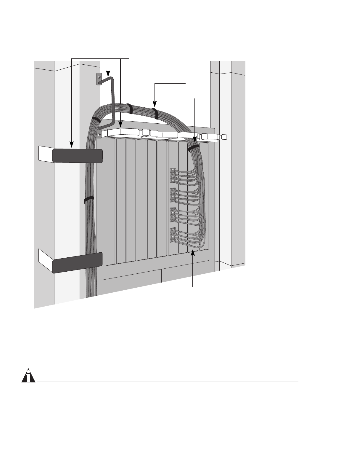
Consider the following recommendations when you connect cable to your network equipment:
• Examine cable for cuts, bends, and nicks.
• Support cable using a cable manager that is mounted above connectors to avoid unnecessary weight
on the cable bundles.
• Use cable managers to route cable bundles to the left and right of the network equipment to
maximize accessibility to the connectors .
• Provide enough slack—approximately 2 to 3 inches (5.08-7.62 cm)— to provide proper strain relief as
shown in Figure 6.
• Bundle cable using velcro straps to avoid injuring cables.
• If you build your own cable, ensure that cable is properly crim ped.
• When installing a patch pan el using twisted pair wiring, unt wist no more than 1 inch (2.54 cm ) of
the cable to avoid RF interference.
• When required for safety and fire rating requirements, use plenum-rated cable. See your local
building codes for determining when it is appropriate to use plenum-rated cable, or refer to IEC
standard 850.
• Keep all ports and connectors free of dust.
NOTE
Unshielded twisted pair (UTP) cable can build up ES D charges when being pulled into a new
installation. Before installing c ategory 5 UTP cables, discharg e ESD from the cable by plugging it into a
port on a switch or a ny network device that is not powered on.
Extreme Networks BlackDiamond 10K-Series Switch Installation Guide 29
Site Preparation
Figure 6: Properly install ed and bundled cable
Cable managers supporting
and directing cables
Proper
bundling
of cables
Adequate
slack, and
bend radius
SPG_008
Fiber Optic Cable
Fiber optic cable must be treated gently during installation. Every cable has a minimum bend radius, for
example, and fibers will be damaged if the cables are bent too sharply. It is also important not to stretch
the cable during installation. We recommend that the bend radius for fiber optic cable equals 2 -inch
(5.08 cm) minimum for each 90 degree turn as shown in Figure 7.
NOTE
Kinks and shar p bends can destr oy or impair the cable’s ability to convey light pulses accurately from
one end of the cable to the other. Use care in dres sing the optical-fiber cables: provide satisfactory
strain relief to suppor t the cable and mai ntain an adequate bend rad ius at all cable turns, par ticular ly
where the cable connects to the I/O module.
30 Extreme Networks BlackDiamond 10K -Series Switch Installation Guide
 Loading...