

Extreme Networks AP6562 operation manual
AP6562 Access Point
INSTALLATION GUIDE

2 AP6562 Access Point
MOTOROLA SOLUTIONS and the Stylized M Logo are registered in the US Patent & Trademark Office. © Motorola Solutions,
Inc. 2013. All rights reserved.

Installation Guide 3
1.0 Introduction . . . . . . . . . . . . . . . . . . . . . . . . . . . . . . . . . . . . . . . . . . . . . . . . . . . . . . 5
1.1 Document Conventions . . . . . . . . . . . . . . . . . . . . . . . . . . . . . . . . . . . . . . . . . . . . 5
1.2 Warnings . . . . . . . . . . . . . . . . . . . . . . . . . . . . . . . . . . . . . . . . . . . . . . . . . . . . . . . 6
1.3 Site Preparation . . . . . . . . . . . . . . . . . . . . . . . . . . . . . . . . . . . . . . . . . . . . . . . . . . 6
1.4 AP6562 Package Contents . . . . . . . . . . . . . . . . . . . . . . . . . . . . . . . . . . . . . . . . . . 6
1.4.1 Internal Antenna Model Package Contents . . . . . . . . . . . . . . . . . . . . . . . . . 6
1.4.2 External Antenna Model Package Contents . . . . . . . . . . . . . . . . . . . . . . . . 7
1.4.3 Features . . . . . . . . . . . . . . . . . . . . . . . . . . . . . . . . . . . . . . . . . . . . . . . . . . . . 7
2.0 Hardware Installation . . . . . . . . . . . . . . . . . . . . . . . . . . . . . . . . . . . . . . . . . . . . . . 8
2.1 Installation Instructions . . . . . . . . . . . . . . . . . . . . . . . . . . . . . . . . . . . . . . . . . . . . 8
2.2 Access Point Placement . . . . . . . . . . . . . . . . . . . . . . . . . . . . . . . . . . . . . . . . . . . . 8
2.3 AP6562 Hardware Mouting and Installation . . . . . . . . . . . . . . . . . . . . . . . . . . . . 9
2.3.1 Mounting Bracket Kit . . . . . . . . . . . . . . . . . . . . . . . . . . . . . . . . . . . . . . . . . . 9
2.3.2 Extension Arm Kit. . . . . . . . . . . . . . . . . . . . . . . . . . . . . . . . . . . . . . . . . . . . 10
2.3.3 Pole Mounted Installations . . . . . . . . . . . . . . . . . . . . . . . . . . . . . . . . . . . . 11
2.3.4 Vertical Pole Mount . . . . . . . . . . . . . . . . . . . . . . . . . . . . . . . . . . . . . . . . . . 12
2.3.5 Wall Mounted Installation . . . . . . . . . . . . . . . . . . . . . . . . . . . . . . . . . . . . . 15
2.4 AP6562 Internal Antenna Model Antenna Options . . . . . . . . . . . . . . . . . . . . . . 17
2.5 AP6562 External Antenna Model Antenna Options. . . . . . . . . . . . . . . . . . . . . . 18
2.6 AP6562 LED Indicators . . . . . . . . . . . . . . . . . . . . . . . . . . . . . . . . . . . . . . . . . . . . 20
3.0 Basic Access Point Configuration . . . . . . . . . . . . . . . . . . . . . . . . . . . . . . . . . . 22
4.0 Specifications. . . . . . . . . . . . . . . . . . . . . . . . . . . . . . . . . . . . . . . . . . . . . . . . . . . . 33
4.1 AP6562 Internal Antenna Model Electrical Specifications . . . . . . . . . . . . . . . . 33
4.2 AP6562 Internal Antenna Model Physical Specifications . . . . . . . . . . . . . . . . . 33
4.3 AP6562 Internal Antenna Model Antenna Specifications . . . . . . . . . . . . . . . . . 33
4.4 AP6562 External Antenna Model Electrical Specifications . . . . . . . . . . . . . . . . 34
4.5 AP6562 External Antenna Model Physical Specifications. . . . . . . . . . . . . . . . . 34
4.6 Radio Specifications. . . . . . . . . . . . . . . . . . . . . . . . . . . . . . . . . . . . . . . . . . . . . . 35

4 AP6562 Access Point
5.0 Regulatory Information . . . . . . . . . . . . . . . . . . . . . . . . . . . . . . . . . . . . . . . . . . . . 36
5.1 Regulatory Information. . . . . . . . . . . . . . . . . . . . . . . . . . . . . . . . . . . . . . . . . . . . 36
5.2 Wireless Device Country Approvals. . . . . . . . . . . . . . . . . . . . . . . . . . . . . . . . . . 36
5.2.1 Country Selection . . . . . . . . . . . . . . . . . . . . . . . . . . . . . . . . . . . . . . . . . . . . 36
5.2.2 Frequency of Operation - FCC and IC . . . . . . . . . . . . . . . . . . . . . . . . . . . . . 37
5.3 Health and Safety Recommendations . . . . . . . . . . . . . . . . . . . . . . . . . . . . . . . . 37
5.3.1 Warnings for Wireless Devices . . . . . . . . . . . . . . . . . . . . . . . . . . . . . . . . . 37
5.3.2 Potentially Hazardous Atmospheres - Fixed Installations . . . . . . . . . . . . . 37
5.3.3 Safety in Hospitals . . . . . . . . . . . . . . . . . . . . . . . . . . . . . . . . . . . . . . . . . . . 38
5.4 RF Exposure Guidelines . . . . . . . . . . . . . . . . . . . . . . . . . . . . . . . . . . . . . . . . . . . 38
5.5 International . . . . . . . . . . . . . . . . . . . . . . . . . . . . . . . . . . . . . . . . . . . . . . . . . . . . 38
5.6 Europe . . . . . . . . . . . . . . . . . . . . . . . . . . . . . . . . . . . . . . . . . . . . . . . . . . . . . . . . 38
5.7 US and Canada . . . . . . . . . . . . . . . . . . . . . . . . . . . . . . . . . . . . . . . . . . . . . . . . . . 39
5.8 Power Supply . . . . . . . . . . . . . . . . . . . . . . . . . . . . . . . . . . . . . . . . . . . . . . . . . . . 39
5.9 Radio Frequency Interference Requirements - FCC . . . . . . . . . . . . . . . . . . . . . . 39
5.10 Radio Frequency Interference Requirements - Canada . . . . . . . . . . . . . . . . . . 40
5.11 CE Marking ad European Economic Area (EEA) . . . . . . . . . . . . . . . . . . . . . . . . 41
5.12 Statement of Compliance . . . . . . . . . . . . . . . . . . . . . . . . . . . . . . . . . . . . . . . . . 41
5.13 Other Countries. . . . . . . . . . . . . . . . . . . . . . . . . . . . . . . . . . . . . . . . . . . . . . . . . 41
5.13 Waste Electrical and Electronic Waste Equipment (WEEE). . . . . . . . . . . . . . . 43
5.14 Turkish WEEE Statement of Compliance . . . . . . . . . . . . . . . . . . . . . . . . . . . . . 44
6.0 Motorola Solutions Support Center . . . . . . . . . . . . . . . . . . . . . . . . . . . . . . . . . 45
7.0 AP6562 Access Point China ROHS Compliance . . . . . . . . . . . . . . . . . . . . . . 46
Installation Guide 5
!
1 Introduction
The AP6562 access point, a component of the Motorola Solutions wireless controller system, links wireless
802.11abgn devices, enabling the growth of your wireless network with a cost effective alternative to standard
access points. The AP6562 access point provides multiple deployment options.
The AP6562 access point receives all power and transfers data through the same CAT-5 or better Ethernet cable.
An 802.3at Ethernet switch or power supply (specifically rated for the AP6562) is required. Motorola Solutions
recommends the AP-PSBIAS-7161-US or AP-PSBIAS-7161-WW outdoor rated power supply
An AP6562 model access point uses WiNG 5 software as its onboard operating system. The access point’s unique
WiNG 5 software enables the access point to function as either a Virtual Controller AP capable of adopting and
managing up to 24 additional AP6562 access points or a Standalone access point managed by its connected
controller.
If new to Motorola Solutions access point technology, refer to the WiNG Access Point System Reference Guide to
familiarize yourself with access point technology and the feature set supported by the WiNG operating system.
The guide is available at http://supportcentral.motorolasolutions.com/support/product/manuals.do
The AP6562 access point is approved under MODEL: AP-6562.
This document is written for the qualified network device installer.
.
1.1 Document Conventions
The following graphical alerts are used in this document to indicate notable situations:
NOTE Tips, hints, or special requirements that you should take note of.
CAUTION Care is required. Disregarding a caution can result in data loss or
equipment malfunction.
WARNING! Indicates a condition or procedure that could result in personal injury or
equipment damage.

6 AP6562 Access Point
1.2 Warnings
• Read all installation instructions and site survey reports, and verify correct equipment installation before
connecting the access point.
• Remove jewelry and watches before installing this equipment.
• Verify the unit is grounded before connecting it to the power source.
• Verify any device connected to this unit is properly wired and grounded.
• Verify there is adequate ventilation around the device, and that ambient temperatures meet equipment
operation specifications.
1.3 Site Preparation
• Consult your site survey and network analysis reports.
• Assign installation responsibility to the appropriate personnel.
• Identify and document where all installed components are located.
• Identify and prepare Ethernet and console port connections.
• Verify cable lengths are within the maximum allowable distances for optimal signal transmission.
1.4 AP6562 Package Contents
An AP6562 access point is available in internal antenna and external antenna models. Contents differ depending
on the model ordered.
1.4.1 Internal Antenna Model Package Contents
Part Number Description
AP-6562-66030-US AP6562: Outdoor Dual Radio 802.11N US
AP-6562-66030-WR AP6562 Outdoor Dual Radio 802.11N INTL
AP-6562-66030-EU AP6562 Outdoor Dual Radio 802.11N EU
AP6562 internal antenna models (AP-6562-66030-US, AP-6562-66030-WW and AP-6562-66030-EU) include the
following:
• AP6562 access point with internal antennas
• Weatherproof RJ45 plug kit
• AP6562 Installation Guide (This Guide)
Installation Guide 7
1.4.2 External Antenna Model Package Contents
Part Number Description
AP-6562-66040-US AP6562 Outdoor Dual Radio 802.11N US
AP-6562-66040-WR AP6562 Outdoor Dual Radio 802.11N INTL
AP-6562-66040-EU AP6562 Outdoor Dual Radio 802.11N EU
AP6562 external antenna models (AP-6562-66040-US, AP-6562-66040-WW and AP-6562-66040-EU) include the
following:
• AP6562 access point with external antenna connectors
• Weatherproof RJ45 plug kit
• AP6562 Installation Guide (This Guide)
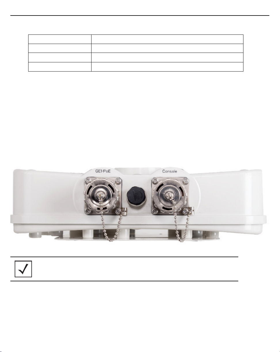
1.4.3 Features
• GE1/PoE LAN port
• Console port
• LED indicators (see
The illustration below is of an internal antenna model.
AP6562 LED Indicators on page 20)
NOTE
When operating in a Gigabit Ethernet environment, CAT-5e or CAT-6 cable
is recommended for Gigabit operation.
The AP6562 access point comes with dual radios supporting 802.11abgn. The access point contains runtime
firmware which enables the unit to boot after a power up. The runtime firmware on the access point and the
firmware downloaded from the connected controller can be updated via the Ethernet interface.
8 AP6562 Access Point
2 Hardware Installation
2.1 Installation Instructions
To prepare for the installation:
1. Match the model number on the purchase order with the model numbers in the packing list and on the
case of the access point.
2. Verify the contents of the box include the intended AP6562 access point, and the included hardware
matches the package contents for an internal antenna access point (see
Package Contents on page 6
Package Contents on page 7
3. Review site survey and network analysis reports to determine the location and mounting position for the
AP6562 access point.
4. Connect a CAT-5 or better Ethernet cable to a compatible 802.3at power source and run the cable to the
installation site. Ensure there is sufficient slack on the cable to perform the installation steps.
NOTE When operating in a Gigabit Ethernet environment, CAT-5e or CAT-6 cable
is recommended for Gigabit operation.
) or external antenna access point (see External Antenna Model
).
Internal Antenna Model
2.2 Access Point Placement
For optimal performance, install the access point away from transformers, heavy-duty motors, fluorescent lights,
microwave ovens, refrigerators and other industrial equipment. Signal loss can occur when metal, concrete, walls
or floors block transmission. Install the access point in an open area or add access points as needed to improve
coverage.
Place the access point using the following guidelines:
• Orient the access point antennas vertically for best reception (applies to external antenna models only).
• When deploying outdoor mesh networks using a pole mounted installation, install the access point at an
ideal height of 30 to 35 feet from the ground.
To maximize the access point’s radio coverage area, Motorola Solutions recommends conducting a site survey to
define and document radio interference obstacles before installing the access point.
Installation Guide 9
2.3 AP6562 Hardware Mounting and Installation
It is recommended to use the AP6562 mounting bracket kit (KT-147407-01) for most deployments. When a standoff
distance is required for a pole mounted or wall mounted installation, use the extension arm kit (KT-150173-01).
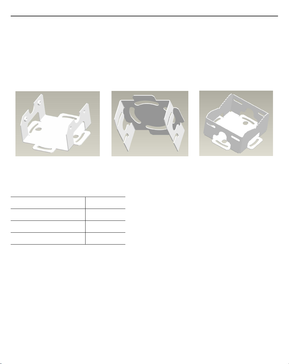
2.3.1 Mounting Bracket Kit
The AP6562 mounting bracket kit (KT-147407-01) includes the access point bracket (left), angle adapter bracket
(center), and pole mount bracket (right) sections:
The access point bracket and the angle adapter bracket can rotated (plus or minus 15 degrees) and tilted (up to 45
degrees) to achieve the required angle and rotation.
The following ancillary hardware to assemble the mounting bracket sections is included in the kit:
Description Quantity
M6 serrated hex flanged screws 8
1/2 inch hex head nut 2
1/2 inch x 3/4 inch hex head bolt 2
:
10 AP6562 Access Point
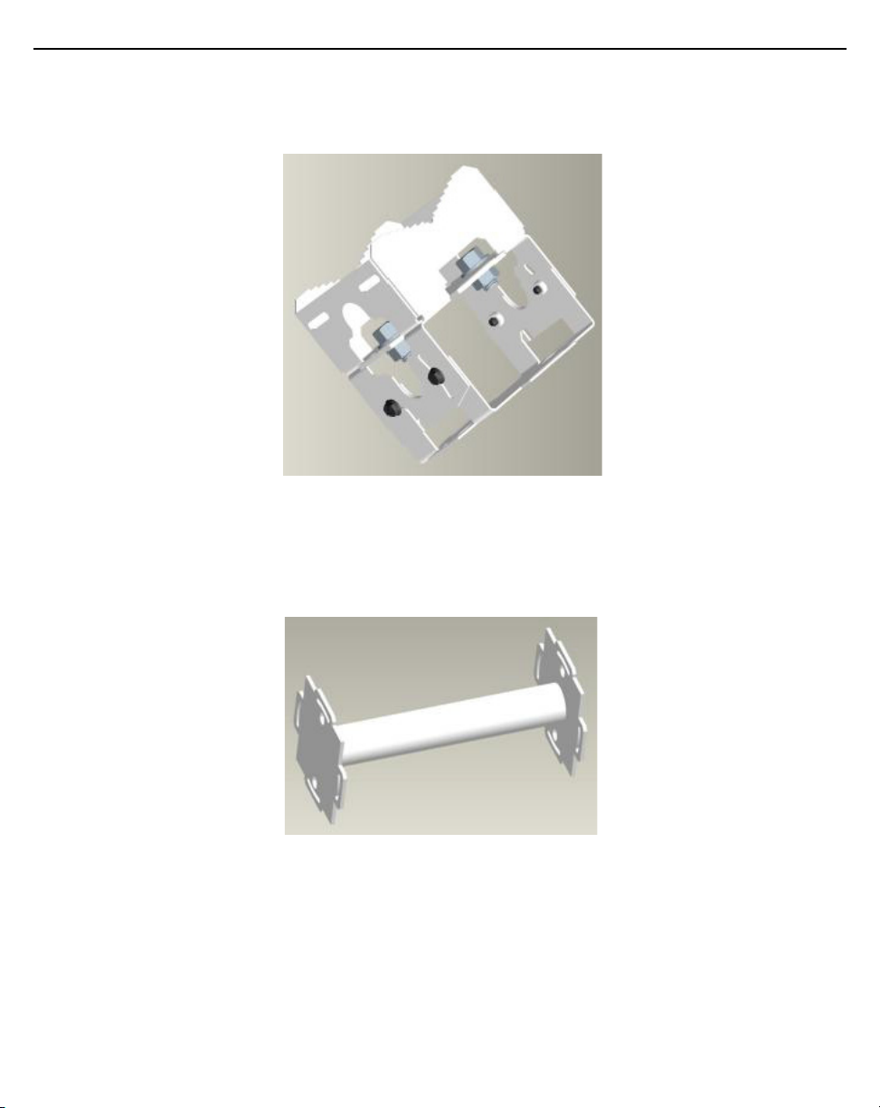
A torque wrench or ratchet with a 10mm adapter, or an adjustable wrench, can be used to assemble the mounting
brackets. A finished assembly of the mounting bracket kit is shown below. Assembly during deployment may
differ to achieve the required angle and rotation.
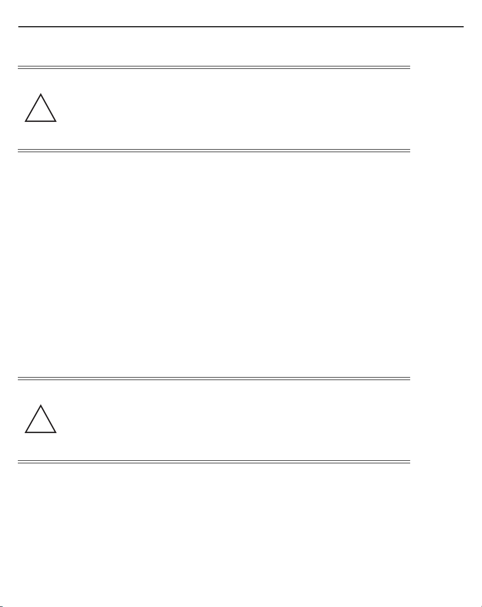
2.3.2 Extension Arm Kit
When mounting an AP6562 on poles more than 3 inches in diameter, use the extension arm kit (KT-150173-01) to
provide a minimum standoff distance of twelve inches to avoid interference with the antennas. The extension arm
kit is only required for AP6562 external antenna models.

Installation Guide 11
The extension arm kit can also be used in combination with the any of the brackets from the mounting bracket kit.
The following ancillary hardware to attach the extension arm to the mounting bracket kit sections is included in
the extension arm kit:
Description Quantity
1/2 inch hex head nut 2
1/2 inch x 3/4 inch hex head bolt 2
2.3.3 Pole Mounted Installations
The mounting hardware kit and extension arm can be used in various combinations to properly install the AP6562
on a pole. For poles of up to 3 inches in diameter, attach the pole mount bracket of the mounting hardware kit at
the desired position on the pole using band clamps up to 3/4 inch width, or a 1/2 inch x 4 inch wide U-bolt and
nuts. For poles greater than 3 inches in diameter, attach the pole mount bracket using band clamps.
NOTE The U-bolt and band clamps are not included in the mounting bracket kit.

12 AP6562 Access Point
NOTE The extension arm is recommended for installations on poles greater than 3 inches in
diameter.
2.3.4 Vertical Pole Mount
Use the following procedures for vertical pole mount installations. The extension arm is recommended when
mounting the access point to poles greater than 3 inches is diameter.
For poles up to 3 inches in diameter when using a U-bolt
1. Thread the two inner nuts onto the U-bolt. Place the U-bolt at the desired mounting location.
2. Place the pole mount bracket section on the U bolt. Adjust the inner nuts until the pole mount bracket
section is against the pole and the U-bolt can be secured tightly to the pole.
3. Place the angle adapter bracket section on the U-bolt with the open slot connections on the bottom and
align it with the pole mount section.
4. Put the two outer nuts on the U-bolt to attach the angle adapter bracket section to the pole mount bracket
section.
5. Tighten all nuts to 300 inch pounds (lbf-in).
6. Position the access point bracket section so that the bottom of the section with the straight (not bevel cut)
side is oriented toward the bottom side of the access point. Using a torque wrench or a ratchet and a
10mm socket, or an adjustable wrench, attach (but don’t tighten) the access point bracket section to the
AP6562 with the with four M6 hex flange screws.
7. Insert two M6 hex flange screws into the bottom holes on the sides of the access point bracket section.
8. Insert the two M6 hex flange screws in the bottom holes on the sides of the access point bracket section
into the open slot connections on the bottom of the angle adapter bracket section.
9. Rotate the access point bracket section upward and align the top holes on the sides with the top holes on
the angle adapter bracket section. Insert two M6 hex flange screws into the top holes on the angle
adapter bracket section.
10. Use a torque wrench or a ratchet and a 10mm socket, or an adjustable wrench, to finish attaching the
access point bracket section to the angle adapter bracket section with the M6 hex flange screws in the
open slot connections and the top holes on the angle adapter bracket section. Do not tighten the screws
until all rotation and tilt adjustments are complete.
11. To adjust the position of the access point, rotate the access point bracket section (plus or minus 15
degrees) and tilt the angle adapter bracket section (up to 45 degrees).
12. Tighten all hex flange screws to 60 inch pounds (lbf-in).
13. If required, install and attach a Kensington security cable (customer supplied) to the unit’s lock port.
14. Attach an Ethernet cable from the access point to a controller with an 802.3at-compatible power source
or use the designated outdoor rated power supply (AP-PSBIAS-7161-US or AP-PSBIAS-7161-WW) to
supply power to the AP6562 (once fully cabled).

Installation Guide 13
!
15. Verify the unit has power by observing that the LEDs are lit or flashing.
CAUTION If not using a 802.3at capable controller to power the AP6562, ensure
only the AP6562’s designated outdoor power supply
(AP-PSBIAS-7161-US or AP-PSBIAS-7161-WW) is used to supply
power to the access point. Using an incorrectly rated power supply
could damage the unit and void the product warranty. Do not actually
connect to the power source until the cabling portion of the
installation is complete.
For mounting with band clamps:
1. Attach the pole mount bracket section at the desired mounting location using band clamps.
2. With the angle adapter bracket section positioned so that the open connector slots are on the bottom,
attach the angle adapter bracket section to the pole mount bracket section using two 1/2 inch bolts and
nuts. Tighten the nuts to 30 inch pounds (lbf-in).
3. Position the access point bracket section so that the bottom of the section with the straight (not bevel cut)
sides is oriented toward the bottom side of the access point. Using a torque wrench or a ratchet and a
10mm socket, or an adjustable wrench, attach (but don’t tighten) the access point bracket section to the
AP6562 with the with four M6 hex flange screws.
4. Insert two M6 hex flange screws into the bottom holes on the sides of the access point bracket section.
5. Insert the two M6 hex flange screws in the bottom holes on the sides of the access point bracket section
into the open slot connections on the bottom of the angle adapter bracket section.
6. Rotate the access point bracket section upward and align the top holes on the sides with the top holes on
the angle adapter bracket section. Insert two M6 hex flange screws into the top holes on the angle
adapter bracket section.
7. Use a torque wrench or a ratchet and a 10mm socket, or an adjustable wrench, to finish attaching the
access point bracket section to the angle adapter bracket section with the M6 hex flange screws in the
open slot connections and the top holes on the angle adapter bracket section. Do not tighten the screws
until all rotation and tilt adjustments are complete.
8. Tighten all hex flange screws to 60 inch pounds (lbf-in).
9. If required, install and attach a Kensington security cable (customer supplied) to the unit’s lock port.
10. Attach an Ethernet cable from the access point to a controller with an 802.3at-compatible power source
or use the designated outdoor rated power supply (AP-PSBIAS-7161-US or AP-PSBIAS-7161-WW) to
supply power to the AP6562 (once fully cabled).
14 AP6562 Access Point
!
!
11. Verify the unit has power by observing that the LEDs are lit or flashing.
CAUTION If not using a 802.3at capable controller to power the AP6562, ensure
only the AP6562’s designated outdoor power supply
(AP-PSBIAS-7161-US or AP-PSBIAS-7161-WW) is used to supply
power to the access point. Using an incorrectly rated power supply
could damage the unit and void the product warranty. Do not actually
connect to the power source until the cabling portion of the
installation is complete.
To use the extension arm with the mounting hardware kit:
1. Attach the pole mount section at the desired mounting location using a U-bolt or band clamps.
2. Complete the steps for assembling and positioning the mounting bracket sections for poles less than or
greater than 3 inches (see
3. Using a torque wrench or a ratchet and a 10mm socket, or an adjustable wrench, attach the extension arm
to the access point bracket section with four M6 hex flange screws. Tighten the hex flange screws to 60
inch pounds (lbf-in).
4. With the access point properly positioned, attach the extension arm to the access point with four M6 hex
flange screws. Tighten the hex flange screws to 60 inch pounds (lbf-in).
5. If required, install and attach a Kensington security cable (customer supplied) to the unit’s lock port.
6. Attach an Ethernet cable from the access point to a controller with an 802.3at-compatible power source
oruse the designated outdoor rated power supply (AP-PSBIAS-7161-US or AP-PSBIAS-7161-WW) to
supply power to the AP6562 (once fully cabled).
7. Verify the unit has power by observing that the LEDs are lit or flashing.
Vertical Pole Mount on page 12).
CAUTION If not using a 802.3at capable controller to power the AP6562, ensure
only the AP6562’s designated outdoor power supply
(AP-PSBIAS-7161-US or AP-PSBIAS-7161-WW) is used to supply
power to the access point. Using an incorrectly rated power supply
could damage the unit and void the product warranty. Do not actually
connect to the power source until the cabling portion of the
installation is complete.
Installation Guide 15
2.3.5 Wall Mounted Installation
For wall mounted installations, use only the access point bracket and if required the angle adapter bracket. The
access point can also be installed using the sheet metal tab on the top of the enclosure.
NOTE The U-bolt and band clamps are not included in the mounting bracket kit.
NOTE The lag bolts are not included in the mounting bracket kit.
1. With the open slot connections facing down, attach the angle adapter bracket section at the desired
mounting location using four #10/32 lag bolts.
2. Using a torque wrench or a ratchet and a 10mm socket, or an adjustable wrench, attach (but don’t tighten)
the access point bracket section to the AP6562 with four M6 hex flange screws and insert two M6 hex
flange screws into the bottom holes on the sides of the access point bracket section.
3. Insert the two M6 hex flange screws in the bottom holes on the sides of the access point bracket section
into the open slot connections on the bottom of the angle adapter bracket section.
4. Rotate the access point bracket section upward and align the top holes on the sides with the top holes on
the angle adapter bracket section. Insert two M6 hex flange screws into the top holes on the angle
adapter bracket section.
5. Use a torque wrench or a ratchet and a 10mm socket, or an adjustable wrench, to finish attaching the
angle adapter bracket section to the access point bracket section with the four M6 hex flange screws in
the open slot connections and the top holes on the angle adapter bracket section. Do not tighten the
screws until all rotation and tilt adjustments are complete.
6. To adjust the position of the access point, rotate the access point bracket section (plus or minus 15
degrees) and tilt the angle adapter bracket section (up to 45 degrees).
7. Tighten all hex flange screws to 60 inch pounds (lbf-in).
8. If required, install and attach a Kensington security cable (customer supplied) to the unit’s lock port.
9. Attach an Ethernet cable from the access point to a controller with an 802.3at-compatible power source
or use the designated outdoor rated power supply (AP-PSBIAS-7161-US or AP-PSBIAS-7161-WW) to
supply power to the AP6562 (once fully cabled).
10. Verify the unit has power by observing that the LEDs are lit or flashing.
 Loading...