

Extreme Networks AP510i operation manual

ExtremeMobility™ AP510i
FCC/WR Installation Guide
9035994-01 Rev AA
Published July 2019

Copyright © 2019 Extreme Networks, Inc. All rights reserved.
Legal Notice
Extreme Networks, Inc. reserves the right to make changes in specifications and other information
contained in this document and its website without prior notice. The reader should in all cases
consult representatives of Extreme Networks to determine whether any such changes have been
made.
The hardware, firmware, software or any specifications described or referred to in this document
are subject to change without notice.
Trademarks
Extreme Networks and the Extreme Networks logo are trademarks or registered trademarks of
Extreme Networks, Inc. in the United States and/or other countries.
All other names (including any product names) mentioned in this document are the property of
their respective owners and may be trademarks or registered trademarks of their respective
companies/owners.
For additional information on Extreme Networks trademarks, please see:
www.extremenetworks.com/company/legal/trademarks
Open Source Declarations
Some software files have been licensed under certain open source or third-party licenses. Enduser license agreements and open source declarations can be found at:
www.extremenetworks.com/support/policies/software-licensing

Table of Contents
Preface................................................................................................................................................................................................4
Conventions.............................................................................................................................................................................4
Providing Feedback to Us................................................................................................................................................ 4
Getting Help............................................................................................................................................................................ 4
Documentation and Training...........................................................................................................................................5
Chapter 1: Overview...................................................................................................................6
Features.....................................................................................................................................................................................6
AP510i LED Status................................................................................................................................................................8
AP510i Powering Methods................................................................................................................................................9
Chapter 2: Installation Process................................................................................................11
Verifying the Box Contents..............................................................................................................................................11
Mounting and Connecting the AP................................................................................................................................11
Mounting Brackets and Accessories Usage............................................................................................................12
Mounting the AP on a Dry or Wood Wall/Solid Flat Ceiling..........................................................................14
Mounting to a Suspended/Drop Ceiling...................................................................................................................21
Mounting to a Junction/Gang box.............................................................................................................................27
Mounting the AP to a Beam..........................................................................................................................................28
Chapter 3: Specifications........................................................................................................29
Chapter 4: Antenna Information........................................................................................... 30
Chapter 5: Regulatory Information....................................................................................... 36
Safety Guidelines................................................................................................................................................................36
Federal Communications Commission (FCC) Notice.......................................................................................36
Industry Canada Notice...................................................................................................................................................37
Brazil Anatel Statement.................................................................................................................................................. 38
Hazardous Substances.................................................................................................................................................... 38
Supplement to Product Instructions.........................................................................................................................38
NCC Statement....................................................................................................................................................................39
CE Information.....................................................................................................................................................................39
European Waste Electrical and Electronic Equipment (WEEE) Notice..................................................40
Declaration of Conformity in Languages of the European Community................................................. 40
Index.......................................................................................................................................... 42
ExtremeMobility™ AP510i FCC/WR Installation Guide 3

Preface
This section discusses the conventions used in this guide, ways to provide feedback, additional help, and
other Extreme Networks® publications.
Conventions
This section discusses the conventions used in this guide.
Providing Feedback to Us
Quality is our first concern at Extreme Networks, and we have made every eort to ensure the accuracy
and completeness of this document. We are always striving to improve our documentation and help
you work better, so we want to hear from you! We welcome all feedback but especially want to know
about:
Content errors or confusing or conflicting information.
•
Ideas for improvements to our documentation so you can find the information you need faster.
•
Broken links or usability issues.
•
If you would like to provide feedback to the Extreme Networks Information Development team, you can
do so in two ways:
Use our short online feedback form at https://www.extremenetworks.com/documentation-
•
feedback/.
Email us at documentation@extremenetworks.com.
•
Please provide the publication title, part number, and as much detail as possible, including the topic
heading and page number if applicable, as well as your suggestions for improvement.
Getting Help
If you require assistance, contact Extreme Networks using one of the following methods:
Extreme
Portal
The Hub A forum for Extreme Networks customers to connect with one another, answer questions, and
Call GTAC For immediate support: 1-800-998-2408 (toll-free in U.S. and Canada) or +1 408-579-2826. For
Before contacting Extreme Networks for technical support, have the following information ready:
Your Extreme Networks service contract number and/or serial numbers for all involved Extreme
•
Networks products
A description of the failure
•
A description of any action(s) already taken to resolve the problem
•
Search the GTAC (Global Technical Assistance Center) knowledge base, manage support cases
and service contracts, download software, and obtain product licensing, training, and
certifications.
share ideas and feedback. This community is monitored by Extreme Networks employees, but is
not intended to replace specific guidance from GTAC.
the support phone number in your country, visit: www.extremenetworks.com/support/contact
ExtremeMobility™ AP510i FCC/WR Installation Guide 4

A description of your network environment (such as layout, cable type, other relevant environmental
•
information)
Network load at the time of trouble (if known)
•
The device history (for example, if you have returned the device before, or if this is a recurring
•
problem)
Any related RMA (Return Material Authorization) numbers
•
Subscribing to Service Notifications
You can subscribe to email notifications for product and software release announcements, Vulnerability
Notices, and Service Notifications.
1 Go to www.extremenetworks.com/support/service-notification-form.
2 Complete the form with your information (all fields are required).
3 Select the products for which you would like to receive notifications.
Note
You can modify your product selections or unsubscribe at any time.
4 Click Submit.
Documentation and Training
To find Extreme Networks product guides, visit our documentation pages at:
Current Product Documentation
Archived Documentation (for earlier
versions and legacy products)
Release Notes www.extremenetworks.com/support/release-notes
Hardware/Software Compatibility Matrices https://www.extremenetworks.com/support/compatibility-matrices/
White papers, data sheets, case studies,
and other product resources
www.extremenetworks.com/documentation/
www.extremenetworks.com/support/documentation-archives/
https://www.extremenetworks.com/resources/
Training
Extreme Networks oers product training courses, both online and in person, as well as specialized
certifications. For more information, visit www.extremenetworks.com/education/.
ExtremeMobility™ AP510i FCC/WR Installation Guide 5

1 Overview
Features
AP510i LED Status
AP510i Powering Methods
The AP510i is a next generation, indoor ceiling mount model enterprise class 802.11ax access point. The
“i” in AP510i indicates that it comes with internal antennas. The AP features a dual-band radio and
comes with eight WiFi internal antennas and one Bluetooth Low Energy (BLE) antenna.
The AP510i can be mounted on a dry or wood wall, solid flat ceiling, junction/ gang box, and on a
suspended or drop ceiling.
Note
The AP510i requires a minimum base firmware of WiNG 7.1.0.0-138R.
Features
The enterprise class 802.11ax AP510i access point has the following features:
Radios: 2 radios; 1 IoT radio (2.4 GHz).
•
Console Port: RJ45.
•
1 x 100/1000/2500/5000 Mbps auto-negotiation Ethernet port, RJ45
•
•
1 x 10/100/1000 Mbps auto-negotiation Ethernet port, RJ45
•
LEDs: 6 – All LEDs will be on during reset (see AP510i LEDs Status for details).
•
One Reset button.
•
Power: PoE 802.3af; 12VDC external power in connector (see AP510i Powering Methods for details).
•
Antennas: – Eight WiFi internal antennas and One BLE internal antenna.
•
Temperature:
•
0°C to +40°C (+32°F to +104°F) @ 6000 ft
•
0°C to +45°C (+32°F to +113°F) @ Sea Level
•
Enclosure: Plastic only.
•
ExtremeMobility™ AP510i FCC/WR Installation Guide 6
Overview
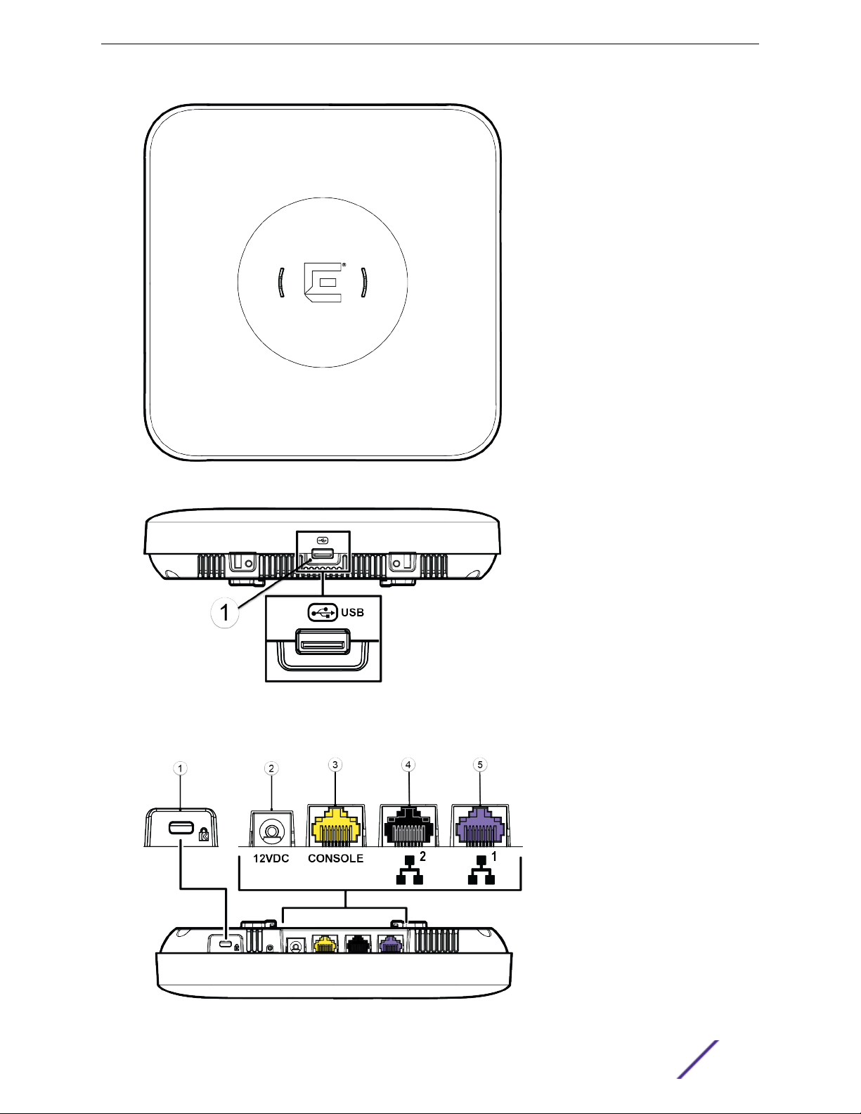
Figure 1: Top view of AP510i
Figure 2: Side view of AP510i
Figure 3: AP510i back ports
ExtremeMobility™ AP510i FCC/WR Installation Guide 7
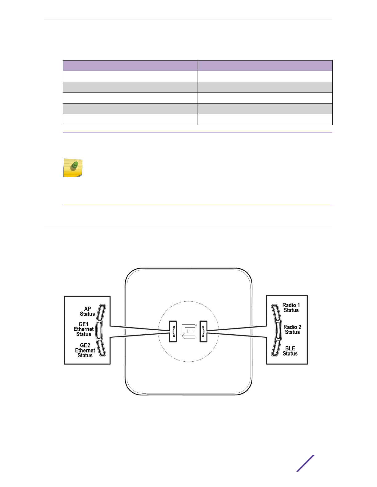
Table 1: Description of back ports of AP510i
Number Description
1 Kensignton Lock
2 12V DC power Supply
3 Console Port (Yellow)
4 LAN 2 (GE) (Black)
5 LAN1 (5 GE) (Purple)
Note
On the access point, there is a hole near the Kensington Lock in the top-rear that can be used
as a provision for safety hangar. There is also a hole on the rear of the access point that can be
used as a safety hangar provision.
The safety hanger can be a wire or a cable that is used to secure the access point and keep it
from falling in case ceiling and wall installation using the main mounting bracket fails.
The Kensington lock can use a 3mm diameter safety hangar cable and the rear hole can
accommodate a 2.9mm diameter safety hangar cable.
Overview
AP510i LED Status
LED Status
The AP510i LEDs are located on the front face of the AP but are not visibly marked.
Figure 4: AP510i LEDs
ExtremeMobility™ AP510i FCC/WR Installation Guide 8

Table 2: AP510i LED Status
LED Icon LED Color Description
Status GREEN Normal operational status
AMBER Non-operational status
GE1 Ethernet AMBER 100Mbps
GREEN 1000Mbps
PURPLE 2.5G/5G
GE2 Ethernet AMBER 100Mbps
GREEN 1000MBps
Radio#1 Status GREEN 2.4GHz
AMBER 5GHz
WHITE Sensor
OFF Non-operational status
Overview
Radio#2 Status AMBER 5GHz
OFF Non-operational status
IoT (BLE) BLUE Indicates BLE is enabled
OFF Non-operational status
AP510i Powering Methods
You can power the AP through the RJ45 Ethernet port (LAN 1 (5GE) and LAN2 (GE) ports), see AP510i
back ports).
If you need to power the AP510i with an external 12V DC power supply, you can plug the power cord
into the power connector on the back of the AP. There is no wall mount bracket for the 12V DC power
supply. When the device is powered on, the power LED on the front face of the AP is lit.
Table 3: AP510i Powering Methods
Power Source Description
Power over Ethernet (PoE) Redundant power is provided through the RJ45
Ethernet ports (LAN ports) of AP510i. The ports are
compliant to be powered with 802.3af and provide full
functionality with 802.3at. This is the preferred method
of powering the AP on ceiling and high wall
installations.
External 12V DC power supply (optional; ordering part
#37219- PWR 12VDC, 3A, 2.5mm x 5.5mm connector)
The AP510i can also be powered by an external DC
power supply plugged into an AC source. Plug the
supply’s input jack into the 12V DC port.
Note
PoE is disabled when external power supply is used.
ExtremeMobility™ AP510i FCC/WR Installation Guide 9

Overview
The following configuration will allow you to bring up the access point in 802.11af power mode. AP510i
802.11af profile:
2x2 (16dBm for both 2.4G and 5G at u.fl connector)
•
Only dual band (mode 1), doesn’t support dual 5G (mode 3)
•
Only 1GE Ethernet, multi-rate Ethernet will be disabled
•
AP510i Power Table
The following table provides information on the status of the back ports on the access point when
powered using 802.3af and 802.3at technology:
AP510i 802.3af 802.3at
Radio 1 2x2 (16dBm) 4x4 (18dBm)
Radio 2 2x2 (16dBm) 4x4 (18dBm)
BLE ON ON
GE1 ON ON
GE2 ON ON
Dual band Yes Yes
Dual 5G No Yes
ExtremeMobility™ AP510i FCC/WR Installation Guide 10

2 Installation Process
Verifying the Box Contents
Mounting and Connecting the AP
Mounting Brackets and Accessories Usage
Mounting the AP on a Dry or Wood Wall/Solid Flat Ceiling
Mounting to a Suspended/Drop Ceiling
Mounting to a Junction/Gang box
Mounting the AP to a Beam
Follow this procedure to install the AP510e access point:
1 Verify the box contents.
2 Review the Safety Guidelines.
3 Mount the AP to a dry or wood wall, solid flat ceiling, on a suspended/drop ceiling, junction/gang
box, or to a beam.
4 Connect the power supply.
Verifying the Box Contents
Before you install the AP3915i access point, make sure that you have all the necessary parts.
Verify that the box contains the following items:
Table 4: AP510i Box Contents
Quantity Items
1 AP510i Quick Reference
1 Mounting bracket for 802.11ax access point (Main
mounting bracket)
1 Cloud Quick Start Card
1 AP510i access point
2 Phillips Pan-head wood screws
2 Screw-in anchors
Mounting and Connecting the AP
Caution
Only qualified personnel should perform installation procedures.
ExtremeMobility™ AP510i FCC/WR Installation Guide 11

Installation Process
Use these instructions as guidelines for mounting and connecting the AP510i easily and safely.
The AP510i comes with a Mounting Bracket (#37201) that can be used to mount the AP on a flat t-bar
with flat ceiling tiles, flat surfaces, beams, and some junction/gang boxes. An adaptor and brackets are
available for mounting the AP to non-flat ceiling tiles and t-bars. To mount the AP510i on a junction/
gang box, use the optional bracket (WS-MBI-WALL04; #30516). All additional and optional parts are
sold separately. For more information on brackets and accessories, refer to Mounting Brackets and
Accessories Usage on page 12 section.
Mounting Brackets and Accessories Usage
The access point comes with the main mounting bracket (#37201; mounting bracket for 802.11ax indoor
access points). There are various optional brackets, an adapter, and bracket accessories that can be
purchased separately.
Table 5: Brackets purchase order information
Part number Description
37201 Main mounting bracket for indoor access points
(included in the access point box), along with the 50
mm M3 security screw pack for main mounting bracket
30518 WS-MBI-DCMTR01 bracket
30516 WS-MBI-WALL04 bracket
37211 WS-MBI-DCFLUSH bracket
Table 6: Bracket accessories purchase order information
Part number Description
KT-135628-01 Universal mounting kit for wireless LAN (WLAN) access
points
37210 Flat metal easy-attach adapter for main mounting
bracket
BRKT-000147A-01 Beam clip accessory
30525; WS-CAB-RJ45-FLT01 RJ45 flat cable accessory for ceiling mount brackets
Table 7: Power supply purchase order information
Part number Description
37219 PWR 12V DC, 3A, 2.5 mm X 5.5 mm connector
ExtremeMobility™ AP510i FCC/WR Installation Guide 12

Installation Process
Table 8: Brackets and accessories usage for various installation options
Mounting
bracket
or
accessory
37201;
main
mounting
bracket
KT-13562
8-01
accessory
; used
with main
mounting
bracket
Wall
install
Yes Yes Yes Yes, by
No No Yes Yes No No Yes 15/16" Wall
Solid flat
ceiling
install
Ceiling
install (Tbar)
Ceiling
install
(protrude
d T-bar)
adding
the
optional
T-bar
adapter
to the
main
mounting
bracket
Junction
box
install
No Yes, by
Beam
install
adding
the beam
clip
accessory
to the
main
mounting
bracket
Ceiling
tile
protrusio
n
No 15/16" This
T-bar
widths
Notes
bracket is
shipped
with the
access
point.
Installatio
n
methods:
Wall
mount or
flush
ceiling
mount
with
single
width.
mount or
protrude
d ceiling
mount
with
single
width.
30518
WS-MBIDCMTR01
bracket
30516
WS-MBIWALL04
bracket
No No Yes Yes No No Yes 9/16", 1.5",
15/16"
Yes No No No Yes No No No Wall
Protrude
d ceiling
mount
with
varying
widths.
mount
with
single
width.
Junction
box
installatio
n.
ExtremeMobility™ AP510i FCC/WR Installation Guide 13
 Loading...