

Extreme Networks Altitude 4600 Series, AP4620-US, AP4621-US, AP4620-ROW, AP4621-ROW Installation Manual
...
Altitude™ 4600 Series Access Point
Installation Guide
Extreme Networks, Inc.
3585 Monroe Street
Santa Clara, California 95051
(888) 257-3000
(408) 579-2800
http://www.extremenetworks.com
Published: May 2011
Part Number: 100369-00 Rev 03

AccessAdapt, Alpine, Altitude, BlackDiamond, EPICenter, ExtremeWorks Essentials, Ethernet
Everywhere, Extreme Enabled, Extreme Ethernet Everywhere, Extreme Networks, Extreme
Standby Router Protocol, Extreme Turbodrive, Extreme Velocity, ExtremeWare, ExtremeWorks,
ExtremeXOS, Go Purple Extreme Solution, ExtremeXOS ScreenPlay, ReachNXT, Sentriant,
ServiceWatch, Summit, SummitStack, Triumph, Unified Access Architecture, Unified Access RF
Manager, UniStack, the Extreme Networks logo, the Alpine logo, the BlackDiamond logo, the
Extreme Turbodrive logo, the Summit logos, and the Powered by ExtremeXOS logo are
trademarks or registered trademarks of Extreme Networks, Inc. or its subsidiaries in the United
States and/or other countries.
sFlow is a registered trademark of InMon Corporation.
Specifications are subject to change without notice.
All other registered trademarks, trademarks, and service marks are property of their respective
owners.
© 2011 Extreme Networks, Inc. All Rights Reserved.
2
Altitude 4600 Series Access Point Installation Guide2Altitude 4600 Series Access Point Installation Guide

Table of Contents
Chapter 1: Introduction.............................................................................................7
Document Conventions ........................................................................................ 7
Warnings............................................................................................................ 8
Site Preparation.................................................................................................. 8
Package Contents ............................................................................................... 9
External Antenna Models - Package Contents
(AP4620-US, AP4621-US, AP4620-ROW and
AP4621-ROW).............................................................................................. 9
Integrated Antenna Models - Package Contents
(AP4610-US, AP4611-US, AP4610-ROW and
AP4611-ROW).............................................................................................. 9
Features....................................................................................................... 9
Chapter 2: Hardware Installation.............................................................................11
Installation Instructions..................................................................................... 11
Precautions ................................................................................................ 13
Access Point Placement .............................................................................. 13
Integrated Antenna Model Wall Mount Instructions ........................................ 13
Wall Mount Hardware ............................................................................ 14
Wall Mount Procedure ........................................................................... 14
Integrated Antenna Suspended Ceiling T-Bar Mount Instructions..................... 15
External Antenna Wall Mount Instructions ..................................................... 16
Wall Mount Hardware ............................................................................ 17
Wall Mount Procedure ........................................................................... 18
External Antenna Suspended Ceiling Tile (Plenum) Mount Instructions ............ 19
Suspended Ceiling Mount Hardware........................................................ 20
Ceiling Mount Procedure........................................................................ 20
Altitude 4600 Series Antenna Options .......................................................... 21
LED Indicators............................................................................................ 21
Software Version 4.x LED States............................................................. 22
Software Version 5.x LED States............................................................. 22
Chapter 3: Specifications .......................................................................................23
Electrical Characteristics ................................................................................... 23
External Antenna Model Physical Characteristics.................................................. 23
Integrated Antenna Model Physical Characteristics............................................... 24
Altitude 4600 Series Access Point Installation Guide
3

Radio Characteristics ........................................................................................ 25
Chapter 4: Basic 4600 Series Configuration............................................................27
Establishing Basic AP Connectivity ..................................................................... 27
Access Point Controller Adoption .................................................................. 27
Chapter 5: Regulatory Compliance .......................................................................... 29
Radio Modules...................................................................................... 30
Wireless Device Country Approvals...................................................................... 30
Country Selection - Note for AP & Wireless Switch ......................................... 31
Frequency of Operation - FCC and IC ............................................................ 31
5 GHz Only........................................................................................... 31
2.4 GHz Only........................................................................................ 32
Health and Safety Recommendations.................................................................. 32
Warnings for the use of Wireless Devices ....................................................... 32
Potentially Hazardous Atmospheres - Fixed Installations ................................. 32
Safety in Hospitals ...................................................................................... 32
Pacemakers.......................................................................................... 32
Other Medical Devices................................................................................. 33
RF Exposure Guidelines..................................................................................... 33
Safety Information ...................................................................................... 33
Reducing RF Exposure—Use Properly ..................................................... 33
International..................................................................................................... 33
EU .................................................................................................................. 34
Remote and Standalone Antenna Configurations ...................................... 34
US and Canada................................................................................................. 34
Co-located statement............................................................................. 34
Remote and Standalone Antenna Configurations ...................................... 34
Power Supply ................................................................................................... 34
Radio Frequency Interference Requirements - FCC............................................... 35
Radio Transmitters (Part 15) .................................................................. 35
Radio Frequency Interference Requirements - Canada .......................................... 36
Radio Transmitters...................................................................................... 36
CE Marking and European Economic Area (EEA) .................................................. 36
Statement of Compliance................................................................................... 37
Turkish WEEE Statement of Compliance ............................................................. 37
Japan (VCCI) - Voluntary Control Council for Interference Class B ITE .................... 37
4
Altitude 4600 Series Access Point Installation Guide

Korea Warning Statement for Class B ITE............................................................ 38
Other Countries ................................................................................................ 38
Australia .................................................................................................... 38
Brazil......................................................................................................... 38
Chile.......................................................................................................... 39
Mexico....................................................................................................... 39
Taiwan....................................................................................................... 39
Korea......................................................................................................... 41
Chapter 6: Waste Electrical and Electronic Equipment (WEEE) ................................. 43
Chapter 7: Customer Support .................................................................................. 45
Registration...................................................................................................... 45
Documentation ................................................................................................. 45
Altitude 4600 Series Access Point Installation Guide
5

6
Altitude 4600 Series Access Point Installation Guide

1 Introduction
NOTE
CAUTION
WARNING!
An Altitude™ 4600 Series Access Point links wireless 802.11a/b/g/n devices to the
controller, enabling growth of your wireless network with a cost-effective alternative to
standard access points. The Altitude 4600 Series Access Point provides two placement
options: wall and ceiling. Wall mount slots fit onto two screws provided. Arrows on the
case guide placement of the screws. For placement above a suspended ceiling, a safety
wire tie point on the case provides for a loop of safety wire. The light pipe fits through
a hole in the ceiling tile to provide a view of the unit’s status lights.
The Altitude 4600 Series Access Point receives all power and transfers data through the
same CAT-5 or better Ethernet cable. There is no additional power supply required. A
Gigabit 802.3af Ethernet controller or Gigabit power-over-Ethernet solution is required.
Document Conventions
The following graphical alerts are used in this document to indicate notable situations
Tips, hints, or special requirements that you should take note of.
Care is required. Disregarding a caution can result in data loss or equipment malfunction.
Indicates a condition or procedure that could result in personal injury or equipment damage.
Altitude 4600 Series Access Point Installation Guide
7

Introduction
Warnings
● Read all installation instructions and site survey reports, and verify correct
equipment installation before connecting the Altitude 4600 Access Point to its power
source.
● Remove jewelry and watches before installing this equipment.
● Verify that the unit is grounded before connecting it to the power source.
● Verify any device connected to this unit is properly wired and grounded.
● Connect all power cords to a properly wired and grounded electrical circuit.
● Verify the electrical circuits have appropriate overload protection.
● Attach only approved power cords to the device.
● Verify the power connector and socket are accessible at all times during the
operation of the equipment.
● Do not work with power circuits in dimly lit spaces.
● Do not install this equipment or work with its power circuits during thunderstorms
or other weather conditions that could cause a power surge.
● Verify there is adequate ventilation around the device, and that ambient
temperatures meet equipment operation specifications.
Site Preparation
● Consult your site survey and network analysis reports to determine specific
equipment placement, power drops, and so on.
● Assign installation responsibility to the appropriate personnel.
● Identify and document where all installed components are located.
● Provide a sufficient number of power drops for your equipment.
● Ensure adequate, dust-free ventilation to all installed equipment.
● Identify and prepare Ethernet and console port connections.
● Verify cable lengths are within the maximum allowable distances for optimal signal
transmission.
8
Altitude 4600 Series Access Point Installation Guide

Package Contents
An Altitude 4600 Series Access Point comes in eight hardware configurations, four
integrated (internal) antenna models and four external antenna models. The contents of
the package differ between the integrated antenna model and the external antenna
model. Both single and dual radio models are supported.
External Antenna Models - Package Contents
(AP4620-US, AP4621-US, AP4620-ROW and
AP4621-ROW)
● Altitude 4600 Series Access Point with external antenna connectors (Plenum Rated)
● Six dual-band (2.4/5 GHz) dipole antennas (AP4620 dual-radio model), or three
dual-band (2.4/5 GHz) dipole antennas (AP4611 single-radio model)
● Two wall mount screws
● Two wall anchors
● Light pipe
● Badge for light pipe
● Altitude 4600 Series Access Point Installation Guide (This Guide)
Integrated Antenna Models - Package Contents
(AP4610-US, AP4611-US, AP4610-ROW and
AP4611-ROW)
● Altitude 4600 Series Access Point with integrated antennas
● Two wall mount screws
● Two wall anchors
● Altitude 4600 Series Access Point Installation Guide (This Guide)
Features
An Altitude 4600 Series Access Point ships with the following features:
Altitude 4600 Series Access Point Installation Guide
9

Introduction
NOTE
● One RJ-45 connector
● LED indicators
● Safety wire tie point
● Slots for wall mounting
● Clips for mounting on a suspended ceiling T-bar
● Lock port for Kensington® style Security Lock
An Altitude 4600 Series Access Point has one RJ-45 connector supporting an 10/100/
1000 Ethernet port and requires 802.3af-compliant power from an external source.
When operating in a Gigabit Ethernet environment CAT-5e or CAT-6 cable is required for Gigabit
operation.
An Altitude 4600 Series Access Point comes in both single and dual radio versions both
supporting 802.11a/b/g/n.
An Altitude 4600 Series Access Point contains runtime firmware which enables the unit
to boot after either a power up or a watchdog reset. The runtime firmware on the access
point and the firmware downloaded from the controller can be updated via the
Ethernet interface from the controller.
10
Altitude 4600 Series Access Point Installation Guide

2 Hardware Installation
Installation Instructions
An Altitude 4600 Series Access Point mounts either on a wall with wide-shoulder
screws or on a suspended ceiling T-bar. This unit is not designed for mounting on a
desk.
To prepare for installation, perform the following steps:
1 Match the model number on the purchase order with the model numbers in the
packing list and on the case of the Altitude 4600 Series Access Point.
2 Verify the contents of the box includes the correct Altitude 4600 model access point.
● AP4610-US - 802.11a/b/g/n dual radio integrated antenna configuration for the
US regulatory domain (Part Number: 15724)
● AP4611-US - 802.11a/b/g/n single radio integrated antenna configuration for the
US regulatory domain (Part Number: 15757)
● AP4610-ROW - 802.11a/b/g/n dual radio integrated antenna configuration for
the ROW (Rest of World domain except Israel) regulatory domain (Part Number:
15725)
● AP4611-ROW - 802.11a/b/g/n single radio integrated antenna configuration for
the ROW (Rest of World domain except Israel) regulatory domain (Part Number:
15735)
● AP4620-US - 802.11a/b/g/n dual radio external antenna configuration for the US
regulatory domain (Part Number: 15730)
● AP4621-US - 802.11a/b/g/n single radio external antenna configuration for the
US regulatory domain (Part Number: 15758)
● AP4620-ROW - 802.11a/b/g/n dual radio external antenna configuration for the
ROW (Rest of World domain except Israel) regulatory domain (Part Number:
15731)
● AP4621-ROW - 802.11a/b/g/n single radio external antenna configuration for the
ROW (Rest of World domain except Israel) regulatory domain (Part Number:
15749)
3 Review site survey and network analysis reports to determine the location and
mounting position for the access point.
Altitude 4600 Series Access Point Installation Guide
11

Hardware Installation
NOTE
4 Connect a CAT-5 or better Ethernet cable to a compatible 802.3af power source and
run the cable to the installation site. Ensure there is sufficient slack on the cable to
perform the installation steps.
When operating in a Gigabit Ethernet environment CAT-5e or CAT-6 cable is required for
Gigabit operation.
12
Altitude 4600 Series Access Point Installation Guide

Precautions
Before installing an Altitude 4600 Series Access Point, verify the following:
● The intended deployment site is not a wet or dusty area.
● The environment has a continuous temperature range between 0° C to 50° C.
Access Point Placement
For optimal performance, install the Altitude 4600 Series Access Point away from
transformers, heavy-duty motors, fluorescent lights, microwave ovens, refrigerators and
other industrial equipment. Signal loss can occur when metal, concrete, walls or floors
block transmission. Install the access point in an open area or add access points as
needed to improve coverage.
Antenna coverage is analogous to lighting. Users might find an area lit from far away to
be not bright enough. An area lit sharply might minimize coverage and create dark
areas. Uniform antenna placement in an area (like even placement of a light bulb)
provides even, efficient coverage.
Place the access point using the following guidelines:
● Install the access point at an ideal height of 10 feet from the ground.
● Orient the access point antennas vertically for best reception.
To maximize the access point’s radio coverage area, Extreme Networks
conducting a site survey to define and document radio interference obstacles before
installing an Altitude 4600 Series Access Point.
®
recommends
Integrated Antenna Model Wall Mount Instructions
This mounting requires hanging the access point along its width or length using the
two slots on the bottom of the unit. An Altitude 4600 Series Access Point can be
mounted onto any plaster, wood, or cement wall surface using the provided wall
anchors. The illustration in the following section shows a lengthwise mount.
Altitude 4600 Series Access Point Installation Guide
13
Hardware Installation
NOTE
Integrated Antenna Wall Mount
Wall Mount Hardware
The following hardware is required to complete the wall mount of an Altitude 4600
Series Access Point:
● Two wide-shoulder Phillips pan head self-tapping screws
● Two wall anchors
● Security cable (optional)
In the event the original mounting screws are lost, the following screws can be used: (ANSI
Standard) #6-18 X 0.875in. Type A or AB Self-Tapping Screw, or (ANSI Standard Metric) M3.5 X
0.6 X 20mm Type D Self-Tapping Screw.
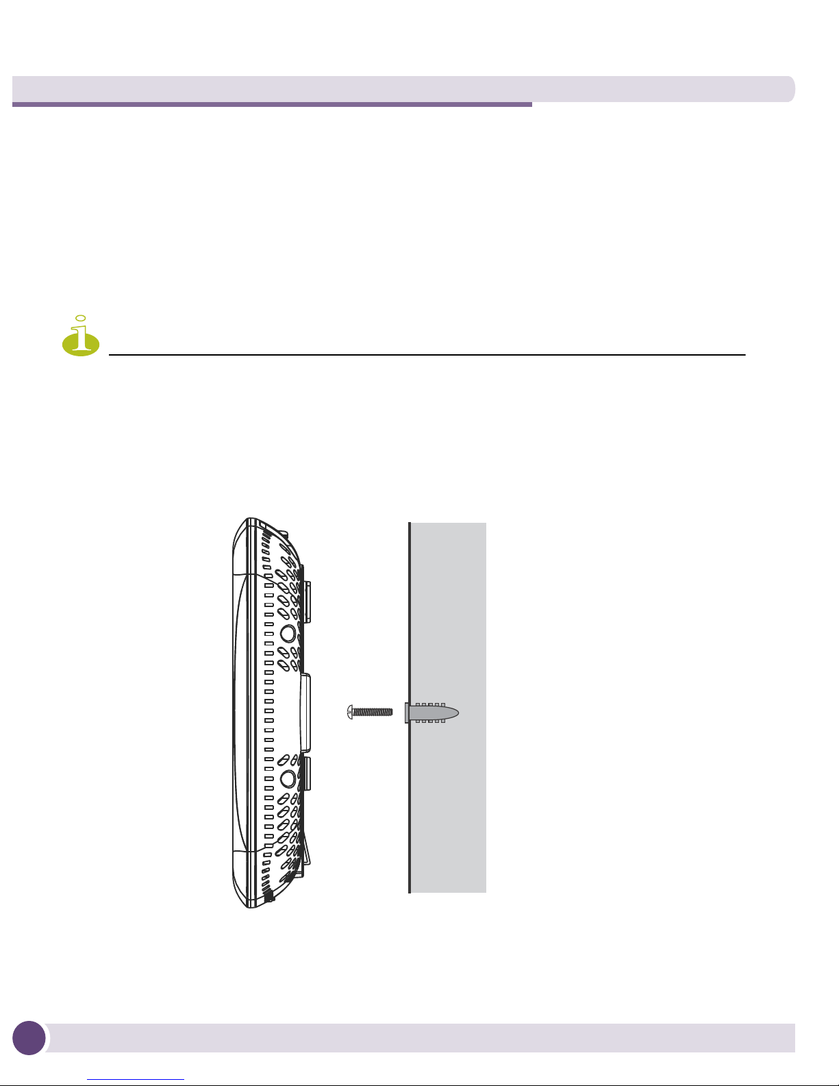
Wall Mount Procedure
14
Altitude 4600 Series Access Point Installation Guide

1 Orient the unit on the wall by its width or length.
NOTE
2 Using the arrows on one edge of the case as guides, move the edge to the midline of
the mounting area and mark points on the midline for the screws.
3 At each point, drill a hole in the wall, insert an anchor, screw into the anchor the
wall mounting screw and stop when there is 1mm between the screw head and the
wall.
When pre-drilling a hole the recommended hole size is 2.8mm (0.11in.) if the screws are
going directly into the wall and 6mm (0.23in.) if the provided wall anchors are being used.
4 If required, install and attach a security cable to the unit’s lock port.
5 Attach the Ethernet cable to the unit and to a controller with an 802.3af-compatible
power source.
6 Place the middle of each of the case’s mount slots over the screw heads.
7 Slide the case down along the mounting surface to hang the mount slots on the
screw heads.
8 Verify the unit has power by observing that the LEDs are lit or flashing.
Integrated Antenna Suspended Ceiling T-Bar Mount
Instructions
Ceiling mount requires holding the Altitude 4600 Series Access Point up against the Tbar of a suspended ceiling grid and twisting the case onto the T-bar.
Altitude 4600 Series Access Point Installation Guide
15
 Loading...