

Extreme Networks AP460i operation manual

ExtremeMobility AP460i/e Outdoor Access
Points
Installation Guide
9036418-00 Rev AA
December 2019

Copyright © 2019 Extreme Networks, Inc. All rights reserved.
Legal Notice
Extreme Networks, Inc. reserves the right to make changes in specifications and other information
contained in this document and its website without prior notice. The reader should in all cases
consult representatives of Extreme Networks to determine whether any such changes have been
made.
The hardware, firmware, software or any specifications described or referred to in this document
are subject to change without notice.
Trademarks
Extreme Networks and the Extreme Networks logo are trademarks or registered trademarks of
Extreme Networks, Inc. in the United States and/or other countries.
All other names (including any product names) mentioned in this document are the property of
their respective owners and may be trademarks or registered trademarks of their respective
companies/owners.
For additional information on Extreme Networks trademarks, please see:
www.extremenetworks.com/company/legal/trademarks
Open Source Declarations
Some software
user license agreements and open source declarations can be found at:
www.extremenetworks.com/support/policies/software-licensing
files have been licensed under certain open source or third-party licenses. End-

Table of Contents
Preface........................................................................................................................................................................................v
Conventions.....................................................................................................................................................................v
Text Conventions..................................................................................................................................................v
Providing Feedback to Us.......................................................................................................................................vi
Getting Help...................................................................................................................................................................vi
Subscribing to Service Notifications........................................................................................................vii
Documentation and Training................................................................................................................................ vii
Training................................................................................................................................................................... vii
AP460i/e Overview.............................................................................................................8
AP460i/e Features......................................................................................................................................................8
LED Indicators..............................................................................................................................................................10
Access Point Purchase Order Information......................................................................................................12
Install the Access Point......................................................................................................13
AP460i/e Box Contents.......................................................................................................................................... 13
Access Point Mounting Options, Brackets, and Accessories................................................................ 14
Position the Access Point before Installation................................................................................................15
Install the Access Point on a Wall or Flat Surface.......................................................................................15
Install the Access Point to a Flat Surface Using KT-147407-02 Flat Part and 1-Axis
Tilt Part....................................................................................................................................................................16
Install the Access Point to a Flat Surface Using the KT-147407-02 Flat Part, 1-axis
Tilt Part, and the KT- 150173-01 Extension Arm...................................................................................17
Install the Access Point On a Flat Surface Using the KT-150173-01 Extension Arm..........19
Install the Access Point on a Flat Surface Using the MBO-ART02 Articulating
Mounting Bracket...............................................................................................................................................19
Install the Access Point on a Flat Surface Using the WS-MBV-VMM Vehicle
Bracket (#32216).................................................................................................................................................21
Install the Access Point on a Pole......................................................................................................................23
Attaching the access point to a pole using all three KT-147407-02 bracket parts.......... 25
Attaching the access point to a pole using the pole part of the KT-147407-02
bracket....................................................................................................................................................................27
Mounting the access point to a pole using pole part of the KT-147407-02 bracket
and the KT-150173-01 extension arm.......................................................................................................28
Mounting the access point to a pole using the KT-147407-02 bracket parts and
the KT-150173-01 extension arm.................................................................................................................29
Attaching the access point to a pole using the WS-MBO-POLE01 bracket and
MBO-ART02 articulating mounting bracket.........................................................................................31
Powering method.............................................................................................................. 34
AP460i/e Power Tables.................................................................................................... 35
AP460i Power Table.................................................................................................................................................35
AP460e Power Table............................................................................................................................................... 35
ExtremeMobility AP460i/e Outdoor Access Points
iii

Table of Contents
GE/Console connections.................................................................................................. 36
Installing the cable gland adapter assembly................................................................................................36
Safely Remove the RJ45 Cable....................................................................................... 39
Antenna configuration for external antenna model.....................................................40
Specifications.....................................................................................................................42
Product specifications.............................................................................................................................................42
Environmental specifications...............................................................................................................................42
Regulatory Information.................................................................................................... 43
Professional Installation Instruction..................................................................................................................43
Installation personnel......................................................................................................................................43
External antenna............................................................................................................................................... 43
Installation procedure.....................................................................................................................................44
Instructions d'installation professionnelle.............................................................................................44
Safety Guidelines.......................................................................................................................................................44
Federal Communications Commission (FCC) Notice..............................................................................44
Industry Canada Notice..........................................................................................................................................45
Detachable Antenna Usage..................................................................................................................................46
Australia Notice..........................................................................................................................................................47
AU co-location MPE Statement.................................................................................................................47
Brazil Anatel Statement..........................................................................................................................................47
Hazardous Substances............................................................................................................................................47
Supplement to Product Instructions................................................................................................................48
NCC Statement...........................................................................................................................................................48
CE Information............................................................................................................................................................48
All operational modes:................................................................................................................................... 49
European Waste Electrical and Electronic Equipment (WEEE) Notice......................................... 49
Declaration of Conformity in Languages of the European Community.........................................50
Index.................................................................................................................................... 53
iv ExtremeMobility AP460i/e Outdoor Access Points

Preface
This section discusses the conventions used in this guide, ways to provide feedback, additional help, and
other Extreme Networks® publications.
Conventions
This section discusses the conventions used in this guide.
Text Conventions
The following tables list text conventions that are used throughout this guide.
Table 1: Notice Icons
Icon Notice Type Alerts you to...
General Notice Helpful tips and notices for using the product.
Note Important features or instructions.
Caution Risk of personal injury, system damage, or loss of data.
Warning Risk of severe personal injury.
New! New Content Displayed next to new content. This is searchable text within
the PDF.
Table 2: Text Conventions
Convention Description
Screen displays
The words enter and
type
This typeface indicates command syntax, or represents information as it
appears on the screen.
When you see the word “enter” in this guide, you must type something, and
then press the Return or Enter key. Do not press the Return or Enter key when
an instruction simply says “type.”
ExtremeMobility AP460i/e Outdoor Access Points v

Providing Feedback to Us
Table 2: Text Conventions (continued)
Convention Description
[Key] names Key names are written with brackets, such as [Return] or [Esc]. If you must
Preface
press two or more keys simultaneously, the key names are linked with a plus
sign (+). Example: Press [Ctrl]+[Alt]+[Del]
Words in italicized
type
Italics emphasize a point or denote new terms at the place where they are
defined in the text. Italics are also used when referring to publication titles.
Providing Feedback to Us
Quality is our first concern at Extreme Networks, and we have made every eort to ensure the accuracy
and completeness of this document. We are always striving to improve our documentation and help
you work better, so we want to hear from you! We welcome all feedback but especially want to know
about:
• Content errors or confusing or conflicting information.
• Ideas for improvements to our documentation so you can
• Broken links or usability issues.
If you would like to provide feedback to the Extreme Networks Information Development team, you can
do so in two ways:
• Use our short online feedback form at https://www.extremenetworks.com/documentation-
feedback/.
• Email us at documentation@extremenetworks.com.
Please provide the publication title, part number, and as much detail as possible, including the topic
heading and page number if applicable, as well as your suggestions for improvement.
find the information you need faster.
Getting Help
If you require assistance, contact Extreme Networks using one of the following methods:
Extreme
Portal
The Hub A forum for Extreme Networks customers to connect with one another, answer questions, and
Call GTAC For immediate support: 1-800-998-2408 (toll-free in U.S. and Canada) or +1 408-579-2826. For
Before contacting Extreme Networks for technical support, have the following information ready:
• Your Extreme Networks service contract number and/or serial numbers for all involved Extreme
Networks products
• A description of the failure
• A description of any action(s) already taken to resolve the problem
vi ExtremeMobility AP460i/e Outdoor Access Points
Search the GTAC (Global Technical Assistance Center) knowledge base, manage support cases
and service contracts, download software, and obtain product licensing, training, and
certifications.
share ideas and feedback. This community is monitored by Extreme Networks employees, but is
not intended to replace specific guidance from GTAC.
the support phone number in your country, visit: www.extremenetworks.com/support/contact

Preface
Subscribing to Service Notifications
• A description of your network environment (such as layout, cable type, other relevant environmental
information)
• Network load at the time of trouble (if known)
• The device history (for example, if you have returned the device before, or if this is a recurring
problem)
• Any related RMA (Return Material Authorization) numbers
Subscribing to Service
You can subscribe to email notifications for product and software release announcements, Vulnerability
Notices, and Service Notifications.
1. Go to www.extremenetworks.com/support/service-notification-form.
2. Complete the form with your information (all fields are required).
3. Select the products for which you would like to receive notifications.
4. Click Submit.
Notifications
Note
You can modify your product selections or unsubscribe at any time.
Documentation and Training
To find Extreme Networks product guides, visit our documentation pages at:
Current Product Documentation
Archived Documentation (for earlier
versions and legacy products)
Release Notes www.extremenetworks.com/support/release-notes
Hardware/Software Compatibility Matrices https://www.extremenetworks.com/support/compatibility-matrices/
White papers, data sheets, case studies,
and other product resources
www.extremenetworks.com/documentation/
www.extremenetworks.com/support/documentation-archives/
https://www.extremenetworks.com/resources/
Training
Extreme Networks
certifications. For more information, visit www.extremenetworks.com/education/.
oers product training courses, both online and in person, as well as specialized
ExtremeMobility AP460i/e Outdoor Access Points vii

AP460i/e Overview
AP460i/e Features on page 8
LED Indicators on page 10
Access Point Purchase Order Information on page 12
The AP460i/e access points are outdoor model enterprise class 802.11ax access points. The “i” in
AP460i indicates that the access point comes with internal antennas and the “e” in AP460e indicates
that it comes with external antenna connectors. The access points feature a dual-band radio, two bandlocked radios, eight WiFi internal or external antennas, and one Bluetooth Low Energy (BLE) antenna.
The AP460i/e can be mounted on a flat surface such as a wall or to a pole.
Note
The AP460i/e requires a minimum base firmware of WiNG 7.3.0.
In this document, the access point is addressed as AP460i/e wherever the procedure and general
information is applicable to both access points.
AP460i/e Features
The AP460i/e access points have the following features:
• Radios:
◦ Three 802.11ax radios (one 2X2 2.4GHz radio, one 4X4 5GHz radio, and one 2X2 2.4GHz and
5GHz radio)
◦ 1 IoT Radio (2.4 GHz)
• Console port: RJ45
• Two Ethernet ports:
◦ 1 x 100/1000/2500 Mbps auto-negotiation Ethernet port, RJ45
◦ 1 x 10/100/1000 Mbps auto-negotiation Ethernet port, RJ45
• LEDs: Seven
◦ All LEDs will be on during reset and connect to general-purpose input/output (GPIO) pins
• One Reset button
• Power: PoE 802.3at (see powering method)
• Antennas:
◦ Eight WiFi internal/external antennas
◦ One BLE internal antenna on AP460i
ExtremeMobility AP460i/e Outdoor Access Points
8
AP460i/e Overview AP460i/e Features
◦ One BLE external antenna port on AP460e
• Temperature: -40°C to +60°C (-40°F to +140°F) @ 6000 ft.
• Enclosure: Plastic with metal base
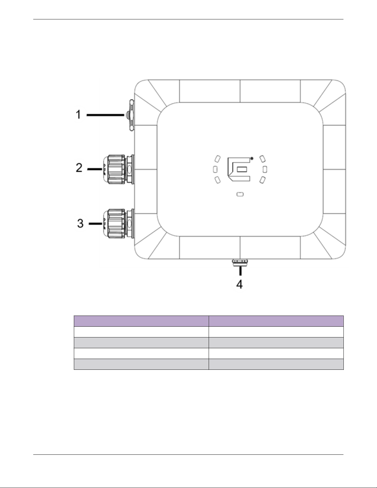
Figure 1: AP460i access point front view
Callout Description
1 Console port and reset button cap
2 GE2
3 GE1-PoE
4 Gore vent
ExtremeMobility AP460i/e Outdoor Access Points 9
LED Indicators
AP460i/e Overview
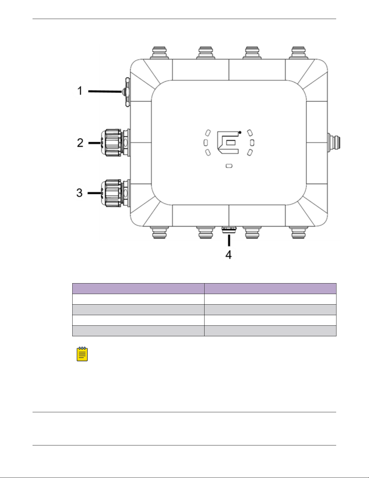
Figure 2: AP460e access point front view
Callout Description
1 Console port and reset button cap
2 GE2
3 GE1-PoE
4 Gore vent
For information on the AP460e antenna connectors, see antenna configuration for external antenna
model access point.
LED Indicators
There are seven LEDs located on the front face of the access point but are not visibly marked.
Note
On the AP460e access point, the sensor and the BLE antennas come with dust caps on them.
Do not remove the dust cap until you need to install the antennas.
10 ExtremeMobility AP460i/e Outdoor Access Points
AP460i/e Overview LED Indicators
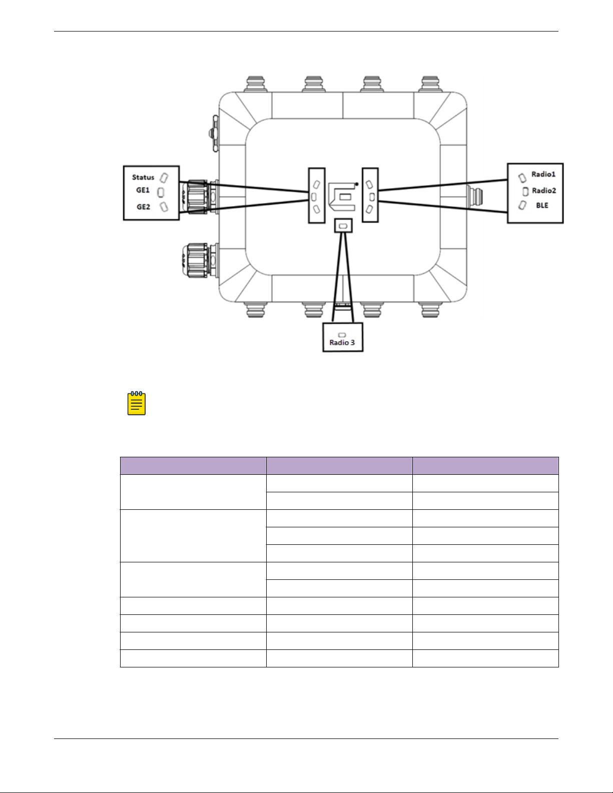
Figure 3: LEDs
Note
The LED icons and the status on AP460i and AP460e are the same.
Table 3: AP460i/e LED status
LED icon LED color Description
Status Green Normal operational status
Amber Non-operational status
GE1 Amber 100Mbps
Green 1000Mbps
Purple 2.5G
GE2 Amber 100Mbps
Green 1000Mbps
Radio 1 Green 2.4G activity
Radio 2 Amber 5G activity
Radio 3 White Sensor activity
BLE Blue BLE is enabled
ExtremeMobility AP460i/e Outdoor Access Points 11

Access Point Purchase Order Information AP460i/e Overview
Access Point Purchase Order Information
The AP460i and AP460e access points must be ordered separately, the ordering details of which are
presented in the tables below:
Table 4: AP460i purchase order information
Part number Description
AP460i-FCC Dual/Tri radio 802.11ax/ac/abgn, 4x4:4 MIMO
outdoor internal antenna access point.
Domain: US, Puerto Rico, and Colombia
AP460i-WR Dual/Tri Radio 802.11ax/ac/abgn, 4x4:4 MIMO
outdoor internal antenna access point.
Domain: EMEA and Rest Of World
AP460i-CAN Dual/Tri Radio 802.11ax/ac/abgn, 4x4:4 MIMO
outdoor internal antenna access point.
Domain: Canada
Table 5: AP460e purchase order information
Part number Description
AP460e-FCC Dual/Tri Radio 802.11ax/ac/abgn, 4x4:4 MIMO
outdoor external antenna access point.
Domain: US, Puerto Rico, and Colombia
AP460e-WR Dual/Tri Radio 802.11ax/ac/abgn, 4x4:4 MIMO
outdoor external antenna access point.
Domain: EMEA and Rest Of World
AP460e-CAN Dual/Tri Radio 802.11ax/ac/abgn, 4x4:4 MIMO
outdoor external antenna access point.
Domain: Canada
12 ExtremeMobility AP460i/e Outdoor Access Points

Install the Access Point
AP460i/e Box Contents on page 13
Access Point Mounting Options, Brackets, and Accessories on page 14
Position the Access Point before Installation on page 15
Install the Access Point on a Wall or Flat Surface on page 15
Install the Access Point on a Pole on page 23
About This Task
The AP460i/e access points can be installed to a flat surface such as a wall or to a pole. Refer to the
purchase order information to know more about selecting the right access point for your installation
needs.
When you receive the access point bundle, perform a visual inspection of the access point, the bracket,
and accessories for any physical damage. Contact Extreme Networks Support if there is any damage.
Before installing the access point:
Procedure
1. Verify the box contents.
2. Read and review the safety guidelines.
AP460i/e Box Contents
The box contains the access point and comes with removable label for your documentation. There is
also a label that mentions the minimum base firmware version that the product needs to have.
Table 6: AP460i/e box contents
Quantity Description
1 AP460i/e Quick Reference
1 Access point (AP460i or AP460e)
1 Hardware bag containing:
• One ground screw
• One ring terminal
• One star washer
ExtremeMobility AP460i/e Outdoor Access Points 13

Access Point Mounting Options, Brackets, and
Accessories Install the Access Point
Access Point Mounting Options, Brackets, and Accessories
The AP460i/e access points are mounted on a flat surface such as a wall or to a pole, which are
described in the following table:
Table 7: AP460i/e mounting brackets and accessories usage
Mounting bracket and
part number
KT-147407-02; bracket;
comes with three parts:
• Flat part
• 1-axis tilt part
• Pole part
KT-150173-01; extension
arm; used with
KT-147407-02 bracket
parts
MBO-ART02; 10" 2-Axis
articulating mounting
bracket
Wall install Pole install Notes
Yes Yes For attaching to a wall
or a flat surface, use the
bracket part that has
two holes on the surface
of the metal portion;
also called the flat part.
For attaching to a pole,
if the 1-axis tilt is not
required, attach the pole
part of the bracket to
the access point. If 1-axis
tilt is required, attach
the pole part of the
KT-147407-02 bracket
on top of the second
wall part.
Yes; use the flat wall
mount part of the
KT-147407-02 bracket
Yes Yes; attach the MBO-
Yes; use the pole mount
bracket part of the
KT-147407-02 bracket
or use all three
KT-147407-02 bracket
parts
ART02 articulating
mounting bracket to the
WS-MBO-POLE01
bracket
The KT-150173-01
extension arm can also
be used by itself without
the other KT-147407-02
bracket parts.
The wall must be strong
enough to support the
AP during inclement
weather.
14 ExtremeMobility AP460i/e Outdoor Access Points

Install the Access Point Position the Access Point before Installation
Table 7: AP460i/e mounting brackets and accessories usage (continued)
Mounting bracket and
part number
WS-MBO-POLE01
bracket
WS-MBV-VMM Vehicle
Bracket (#32216);
comes with fours parts
Note
All brackets and accessories are sold separately.
Wall install Pole install Notes
No Yes; the POLE01 bracket
can only be used with
the MBO-ART02
articulating mounting
bracket
Yes No None
Position the Access Point before Installation
If the pole diameter is
<= 1" (25.4mm), use
small cable clamp. If the
pole diameter is
between 5" - 7"
(178mm), use large
cable clamp. For any
other pole diameter,
provide your own
stainless steel cable
clamp. The band must
be 1/2” (12.7mm) wide.
When you install the access point, the gore vent must be on the side closest to the ground, and not
above the plastic cover. You must provide a 3-inch drip loop on all cables.
Note
The sensor and BLE antennas come with dust cap on them. Do not remove the dust cap until
you need to install the antennas.
Install the Access Point on a Wall or Flat Surface
You can install the access point on a flat surface such as a wall using the following brackets:
• KT-147407-02 bracket
• KT-150173-01 extension arm
• MBO-ART02 10" 2-axis articulating mounting bracket
• WS-MBV-VMM vehicle bracket (#32216)
Note
The wall install options are applicable to both internal and external antenna model outdoor
access points.
ExtremeMobility AP460i/e Outdoor Access Points 15
Install the Access Point to a Flat Surface Using
KT-147407-02 Flat Part and 1-Axis Tilt Part Install the Access Point
Install the Access Point to a Flat Surface Using KT-147407-02 Flat Part and 1-Axis Tilt Part
Before You Begin
The KT-147407-02 bracket has three bracket parts; flat part, 1-axis tilt part, and the pole part. For this
installation, you require the flat part and the 1-axis tilt part.
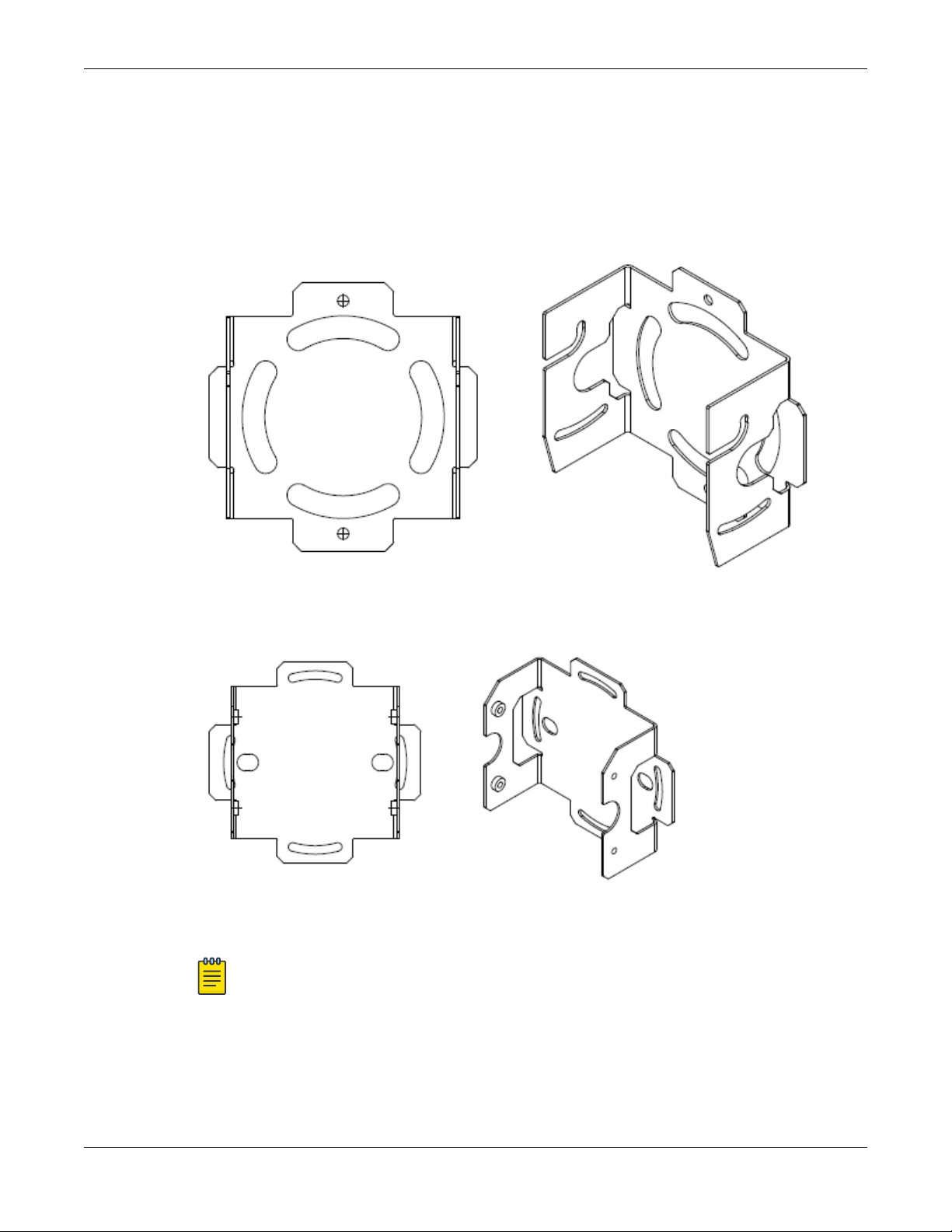
Figure 4: KT-147407-02 bracket flat part
Figure 5: KT-147407-02 bracket 1-axis tilt part
Note
The flat part and the 1-axis tilt part can be used interchangeably with the access points. You
can either attach the flat part or the 1-axis tilt part first and the rest of the installation
procedure will not be aected by it.
16 ExtremeMobility AP460i/e Outdoor Access Points

Install the Access Point
The following hardware is required:
• KT-147407-02 flat part
• KT-147407-02 1-axis tilt part
• Access point
• Ten M6 hex-head screws
◦ Two M6 screws to attach the KT-147407-02
◦ Four M6 screws to attach the KT-147407-02 1-axis tilt part to a flat surface
◦ Four M6 screws to attach the KT-147407-02
Procedure
1. Attach the KT-147407-02 flat part to the access point using two M6 hex-head screws.
2. Using the 1-axis tilt part as a template, mark and drill four holes on a wall or a flat surface.
3. Attach the 1-axis tilt part to a wall or a flat surface using four M6 head-size screws.
4. Align the KT-147407-02 flat part bracket inside the 1-axis tilt part, and attach it using four M6 screws.
5. Tilt the access point to a desired angle and tighten the four M6 screws to a torque of 45 in-lbs.
The tilt bracket can be adjusted from +15 degrees to -15 degrees of tilt.
Install the Access Point to a Flat Surface Using the
KT-147407-02 Flat Part, 1-axis Tilt Part, and the KT-
150173-01 Extension Arm
flat part to the access point
flat part to the 1-axis tilt part
Install the Access Point to a Flat Surface Using the KT-147407-02 Flat Part, 1-axis Tilt Part, and the KT- 150173-01 Extension Arm
Before You Begin
In installations that require an extension arm, the access point is attached to a flat surface using the
KT-147407-02 bracket parts and the KT-150173-01 extension arm.
ExtremeMobility AP460i/e Outdoor Access Points 17
 Loading...