

Page 1

ExtremeMobility AP460i/e
Outdoor Access Points
Installation Guide
9036418-00 Rev AA
Published November 2019
Page 2

Copyright © 2019 Extreme Networks, Inc. All rights reserved.
Legal Notice
Extreme Networks, Inc. reserves the right to make changes in specifications and other information
contained in this document and its website without prior notice. The reader should in all cases
consult representatives of Extreme Networks to determine whether any such changes have been
made.
The hardware, firmware, software or any specifications described or referred to in this document
are subject to change without notice.
Trademarks
Extreme Networks and the Extreme Networks logo are trademarks or registered trademarks of
Extreme Networks, Inc. in the United States and/or other countries.
All other names (including any product names) mentioned in this document are the property of
their respective owners and may be trademarks or registered trademarks of their respective
companies/owners.
For additional information on Extreme Networks trademarks, please see:
www.extremenetworks.com/company/legal/trademarks
Open Source Declarations
Some software files have been licensed under certain open source or third-party licenses. Enduser license agreements and open source declarations can be found at:
www.extremenetworks.com/support/policies/software-licensing
Page 3

Table of Contents
Preface................................................................................................................................................................................................4
Conventions.............................................................................................................................................................................4
Providing Feedback to Us.................................................................................................................................................5
Getting Help.............................................................................................................................................................................5
Documentation and Training...........................................................................................................................................6
Chapter 1: AP460i/e Overview................................................................................................ 7
AP460i/e Features...............................................................................................................................................................7
LED Indicators........................................................................................................................................................................ 9
Access Point Purchase Order Information............................................................................................................... 11
Chapter 2: Install the Access Point........................................................................................ 12
AP460i/e Box Contents...................................................................................................................................................12
Access Point Mounting Options, Brackets, and Accessories......................................................................... 12
Position the Access Point before Installation........................................................................................................ 14
Install the Access Point on a Wall or Flat Surface...............................................................................................14
Install the Access Point on a Pole.............................................................................................................................. 20
Chapter 3: Powering method................................................................................................. 30
Chapter 4: GE/Console connections..................................................................................... 31
Installing the cable gland adapter assembly..........................................................................................................31
Chapter 5: Antenna configuration for external antenna model........................................34
Chapter 6: Specifications........................................................................................................36
Chapter 7: Regulatory Information....................................................................................... 37
Professional Installation Instruction...........................................................................................................................37
Safety Guidelines................................................................................................................................................................38
Federal Communications Commission (FCC) Notice.......................................................................................38
Industry Canada Notice...................................................................................................................................................39
Detachable Antenna Usage..........................................................................................................................................40
Australia Notice....................................................................................................................................................................41
Brazil Anatel Statement................................................................................................................................................... 41
Hazardous Substances..................................................................................................................................................... 41
Supplement to Product Instructions.........................................................................................................................42
NCC Statement....................................................................................................................................................................42
CE Information.....................................................................................................................................................................42
European Waste Electrical and Electronic Equipment (WEEE) Notice.................................................. 43
Declaration of Conformity in Languages of the European Community................................................. 44
Index.......................................................................................................................................... 47
ExtremeMobility AP460i/e Outdoor Access Points 3
Page 4

Preface
This section discusses the conventions used in this guide, ways to provide feedback, additional help, and
other Extreme Networks® publications.
Conventions
This section discusses the conventions used in this guide.
Text Conventions
The following tables list text conventions that are used throughout this guide.
Table 1: Notice Icons
Icon Notice Type Alerts you to...
General Notice Helpful tips and notices for using the product.
Note Important features or instructions.
Caution Risk of personal injury, system damage, or loss of data.
Warning Risk of severe personal injury.
New!
New Content Displayed next to new content. This is searchable text within the PDF.
Table 2: Text Conventions
Convention Description
Screen displays
The words enter and
type
[Key] names Key names are written with brackets, such as [Return] or [Esc]. If you must press two
Words in italicized type Italics emphasize a point or denote new terms at the place where they are defined in
This typeface indicates command syntax, or represents information as it appears on the
screen.
When you see the word “enter” in this guide, you must type something, and then press
the Return or Enter key. Do not press the Return or Enter key when an instruction
simply says “type.”
or more keys simultaneously, the key names are linked with a plus sign (+). Example:
Press [Ctrl]+[Alt]+[Del]
the text. Italics are also used when referring to publication titles.
ExtremeMobility AP460i/e Outdoor Access Points 4
Page 5

Providing Feedback to Us
Quality is our first concern at Extreme Networks, and we have made every eort to ensure the accuracy
and completeness of this document. We are always striving to improve our documentation and help
you work better, so we want to hear from you! We welcome all feedback but especially want to know
about:
Content errors or confusing or conflicting information.
•
Ideas for improvements to our documentation so you can find the information you need faster.
•
Broken links or usability issues.
•
If you would like to provide feedback to the Extreme Networks Information Development team, you can
do so in two ways:
Use our short online feedback form at https://www.extremenetworks.com/documentation-
•
feedback/.
Email us at documentation@extremenetworks.com.
•
Please provide the publication title, part number, and as much detail as possible, including the topic
heading and page number if applicable, as well as your suggestions for improvement.
Getting Help
If you require assistance, contact Extreme Networks using one of the following methods:
Extreme
Portal
The Hub A forum for Extreme Networks customers to connect with one another, answer questions, and
Call GTAC For immediate support: 1-800-998-2408 (toll-free in U.S. and Canada) or +1 408-579-2826. For
Before contacting Extreme Networks for technical support, have the following information ready:
Your Extreme Networks service contract number and/or serial numbers for all involved Extreme
•
Networks products
A description of the failure
•
A description of any action(s) already taken to resolve the problem
•
A description of your network environment (such as layout, cable type, other relevant environmental
•
information)
Network load at the time of trouble (if known)
•
The device history (for example, if you have returned the device before, or if this is a recurring
•
problem)
Any related RMA (Return Material Authorization) numbers
•
Search the GTAC (Global Technical Assistance Center) knowledge base, manage support cases
and service contracts, download software, and obtain product licensing, training, and
certifications.
share ideas and feedback. This community is monitored by Extreme Networks employees, but is
not intended to replace specific guidance from GTAC.
the support phone number in your country, visit: www.extremenetworks.com/support/contact
Subscribing to Service Notifications
You can subscribe to email notifications for product and software release announcements, Vulnerability
Notices, and Service Notifications.
ExtremeMobility AP460i/e Outdoor Access Points 5
Page 6

1 Go to www.extremenetworks.com/support/service-notification-form.
2 Complete the form with your information (all fields are required).
3 Select the products for which you would like to receive notifications.
Note
You can modify your product selections or unsubscribe at any time.
4 Click Submit.
Documentation and Training
To find Extreme Networks product guides, visit our documentation pages at:
Current Product Documentation www.extremenetworks.com/documentation/
Archived Documentation (for earlier
versions and legacy products)
Release Notes www.extremenetworks.com/support/release-notes
Hardware/Software Compatibility Matrices https://www.extremenetworks.com/support/compatibility-matrices/
White papers, data sheets, case studies,
and other product resources
www.extremenetworks.com/support/documentation-archives/
https://www.extremenetworks.com/resources/
Training
Extreme Networks oers product training courses, both online and in person, as well as specialized
certifications. For more information, visit www.extremenetworks.com/education/.
ExtremeMobility AP460i/e Outdoor Access Points 6
Page 7

1 AP460i/e Overview
AP460i/e Features
LED Indicators
Access Point Purchase Order Information
The AP460i/e access points are outdoor model enterprise class 802.11ax access points. The “i” in
AP460i indicates that the access point comes with internal antennas and the “e” in AP460e indicates
that it comes with external antenna connectors. The access points feature a dual-band radio, two bandlocked radios, eight WiFi internal or external antennas, and one Bluetooth Low Energy (BLE) antenna.
The AP460i/e can be mounted on a flat surface such as a wall or to a pole.
Note
The AP460i/e requires a minimum base firmware of WiNG 7.3.0.
In this document, the access point is addressed as AP460i/e wherever the procedure and general
information is applicable to both access points.
AP460i/e Features
The AP460i/e access points have the following features:
Radios:
•
Three 802.11ax radios (one 2X2 2.4GHz radio, one 4X4 5GHz radio, and one 2X2 2.4GHz and
•
5GHz radio)
1 IoT Radio (2.4 GHz)
•
Console port: RJ45
•
Two Ethernet ports:
•
1 x 100/1000/2500 Mbps auto-negotiation Ethernet port, RJ45
•
1 x 10/100/1000 Mbps auto-negotiation Ethernet port, RJ45
•
LEDs: Seven
•
All LEDs will be on during reset and connect to general-purpose input/output (GPIO) pins
•
One Reset button
•
Power: PoE 802.3at (see powering method)
•
Antennas:
•
Eight WiFi internal/external antennas
•
One BLE internal antenna on AP460i
•
One BLE external antenna port on AP460e
•
Temperature: -40°C to +60°C (-40°F to +140°F) @ 6000 ft.
•
Enclosure: Plastic with metal base
•
ExtremeMobility AP460i/e Outdoor Access Points 7
Page 8
AP460i/e Overview
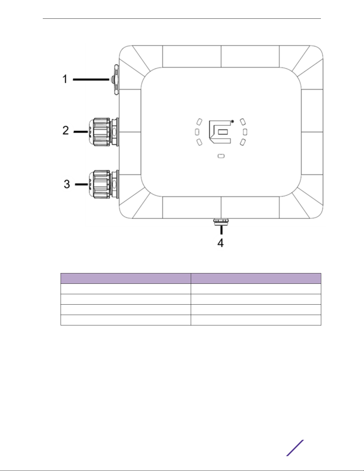
Figure 1: AP460i access point front view
Callout
1 Console port and reset button cap
2 GE2
3 GE1-PoE
4 Gore vent
Description
ExtremeMobility AP460i/e Outdoor Access Points 8
Page 9
AP460i/e Overview
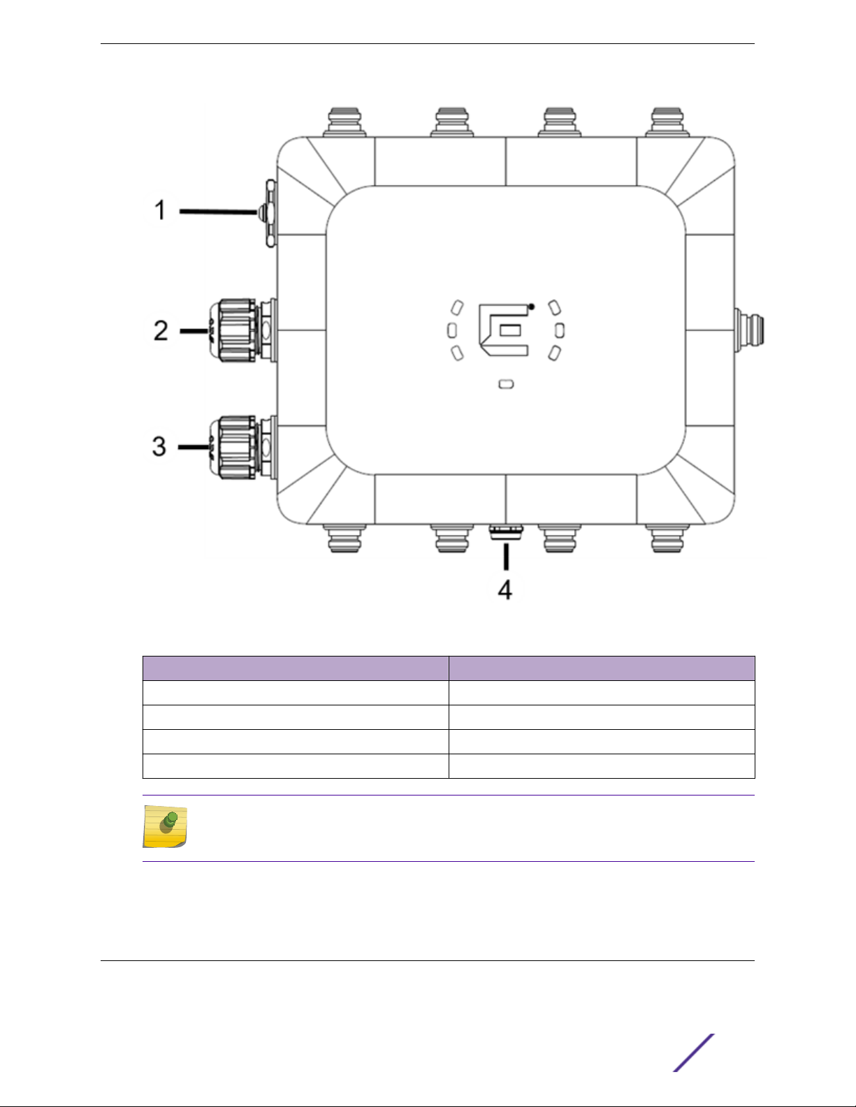
Figure 2: AP460e access point front view
Callout
1 Console port and reset button cap
2 GE2
3 GE1-PoE
4 Gore vent
Description
Note
On the AP460e access point, the sensor and the BLE antennas come with dust caps on them.
Do not remove the dust cap until you need to install the antennas.
For information on the AP460e antenna connectors, see antenna configuration for external antenna
model access point.
LED Indicators
There are seven LEDs located on the front face of the access point but are not visibly marked.
ExtremeMobility AP460i/e Outdoor Access Points 9
Page 10
AP460i/e Overview
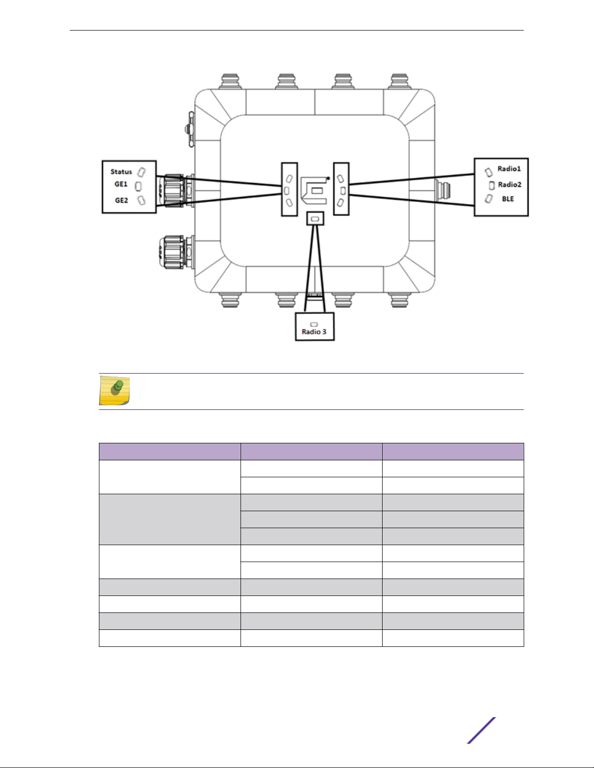
Figure 3: LEDs
Note
The LED icons and the status on AP460i and AP460e are the same.
Table 3: AP460i/e LED status
LED icon LED color Description
Status Green Normal operational status
Amber Non-operational status
GE1 Amber 100Mbps
Green 1000Mbps
Purple 2.5G
GE2 Amber 100Mbps
Green 1000Mbps
Radio 1 Green 2.4G activity
Radio 2 Amber 5G activity
Radio 3 White Sensor activity
BLE Blue BLE is enabled
ExtremeMobility AP460i/e Outdoor Access Points 10
Page 11

AP460i/e Overview
Access Point Purchase Order Information
The AP460i and AP460e access points must be ordered separately, the ordering details of which are
presented in the tables below:
Table 4: AP460i purchase order information
Part number Description
AP460i-FCC Dual/Tri radio 802.11ax/ac/abgn, 4x4:4 MIMO outdoor
internal antenna access point.
Domain: US, Puerto Rico, and Colombia
AP460i-WR Dual/Tri Radio 802.11ax/ac/abgn, 4x4:4 MIMO outdoor
internal antenna access point.
Domain: EMEA and Rest Of World
AP460i Dual/Tri Radio 802.11ax/ac/abgn, 4x4:4 MIMO outdoor
internal antenna access point.
Domain: Canada
Table 5: AP460e purchase order information
Part number Description
AP460e-FCC Dual/Tri Radio 802.11ax/ac/abgn, 4x4:4 MIMO outdoor
external antenna access point.
Domain: US, Puerto Rico, and Colombia
AP460e-WR Dual/Tri Radio 802.11ax/ac/abgn, 4x4:4 MIMO outdoor
external antenna access point.
Domain: EMEA and Rest Of World
AP460e-CAN Dual/Tri Radio 802.11ax/ac/abgn, 4x4:4 MIMO outdoor
external antenna access point.
Domain: Canada
ExtremeMobility AP460i/e Outdoor Access Points 11
Page 12

2 Install the Access Point
AP460i/e Box Contents
Access Point Mounting Options, Brackets, and Accessories
Position the Access Point before Installation
Install the Access Point on a Wall or Flat Surface
Install the Access Point on a Pole
The AP460i/e access points can be installed to a flat surface such as a wall or to a pole. Refer to the
purchase order information to know more about selecting the right access point for your installation
needs.
When you receive the access point bundle, perform a visual inspection of the access point, the bracket,
and accessories for any physical damage. Contact Extreme Networks Support if there is any damage.
Before installing the access point:
1 Verify the box contents.
2 Read and review the safety guidelines.
AP460i/e Box Contents
The box contains the access point and comes with removable label for your documentation. There is
also a label that mentions the minimum base firmware version that the product needs to have.
Table 6: AP460i/e box contents
Quantity Description
1 AP460i/e Quick Reference
1 Access point (AP460i or AP460e)
1 Hardware bag containing:
One ground screw
•
One ring terminal
•
One star washer
•
Access Point Mounting Options, Brackets, and Accessories
The AP460i/e access points are mounted on a flat surface such as a wall or to a pole, which are
described in the following table:
ExtremeMobility AP460i/e Outdoor Access Points 12
Page 13

Table 7: AP460i/e mounting brackets and accessories usage
Install the Access Point
Mounting bracket and part
number
KT-147407-02; bracket;
comes with three parts:
Flat part
•
1-axis tilt part
•
Pole part
•
KT-150173-01; extension
arm; used with
KT-147407-02 bracket
parts
MBO-ART02; 10" 2-Axis
articulating mounting
bracket
Wall install Pole install Notes
Yes Yes For attaching to a wall or a
flat surface, use the
bracket part that has two
holes on the surface of the
metal portion; also called
the flat part. For attaching
to a pole, if the 1-axis tilt is
not required, attach the
pole part of the bracket to
the access point. If 1-axis
tilt is required, attach the
pole part of the
KT-147407-02 bracket on
top of the second wall part.
Yes; use the flat wall mount
part of the KT-147407-02
bracket
Yes Yes; attach the MBO-
Yes; use the pole mount
bracket part of the
KT-147407-02 bracket or
use all three KT-147407-02
bracket parts
ART02 articulating
mounting bracket to the
WS-MBO-POLE01 bracket
The KT-150173-01 extension
arm can also be used by
itself without the other
KT-147407-02 bracket
parts.
The wall must be strong
enough to support the AP
during inclement weather.
WS-MBO-POLE01 bracket No Yes; the POLE01 bracket
can only be used with the
MBO-ART02 articulating
mounting bracket
WS-MBV-VMM Vehicle
Bracket (#32216); comes
with fours parts
Yes No None
Note
All brackets and accessories are sold separately.
If the pole diameter is <= 1"
(25.4mm), use small cable
clamp. If the pole diameter
is between 5" - 7" (178mm),
use large cable clamp. For
any other pole diameter,
provide your own stainless
steel cable clamp. The
band must be 1/2”
(12.7mm) wide.
ExtremeMobility AP460i/e Outdoor Access Points 13
Page 14

Install the Access Point
Position the Access Point before Installation
When you install the access point, the gore vent must be on the side closest to the ground, and not
above the plastic cover. You must provide a 3-inch drip loop on all cables.
Note
The sensor and BLE antennas come with dust cap on them. Do not remove the dust cap until
you need to install the antennas.
Install the Access Point on a Wall or Flat Surface
You can install the access point on a flat surface such as a wall using the following brackets:
KT-147407-02 bracket
•
KT-150173-01 extension arm
•
MBO-ART02 10" 2-axis articulating mounting bracket
•
WS-MBV-VMM vehicle bracket (#32216)
•
Note
The wall install options are applicable to both internal and external antenna model outdoor
access points.
Install the Access Point to a Flat Surface Using KT-147407-02 Flat Part and 1Axis Tilt Part
The KT-147407-02 bracket has three bracket parts; flat part, 1-axis tilt part, and the pole part. For this
installation, you require the flat part and the 1-axis tilt part.
Figure 4: KT-147407-02 bracket flat part
ExtremeMobility AP460i/e Outdoor Access Points 14
Page 15
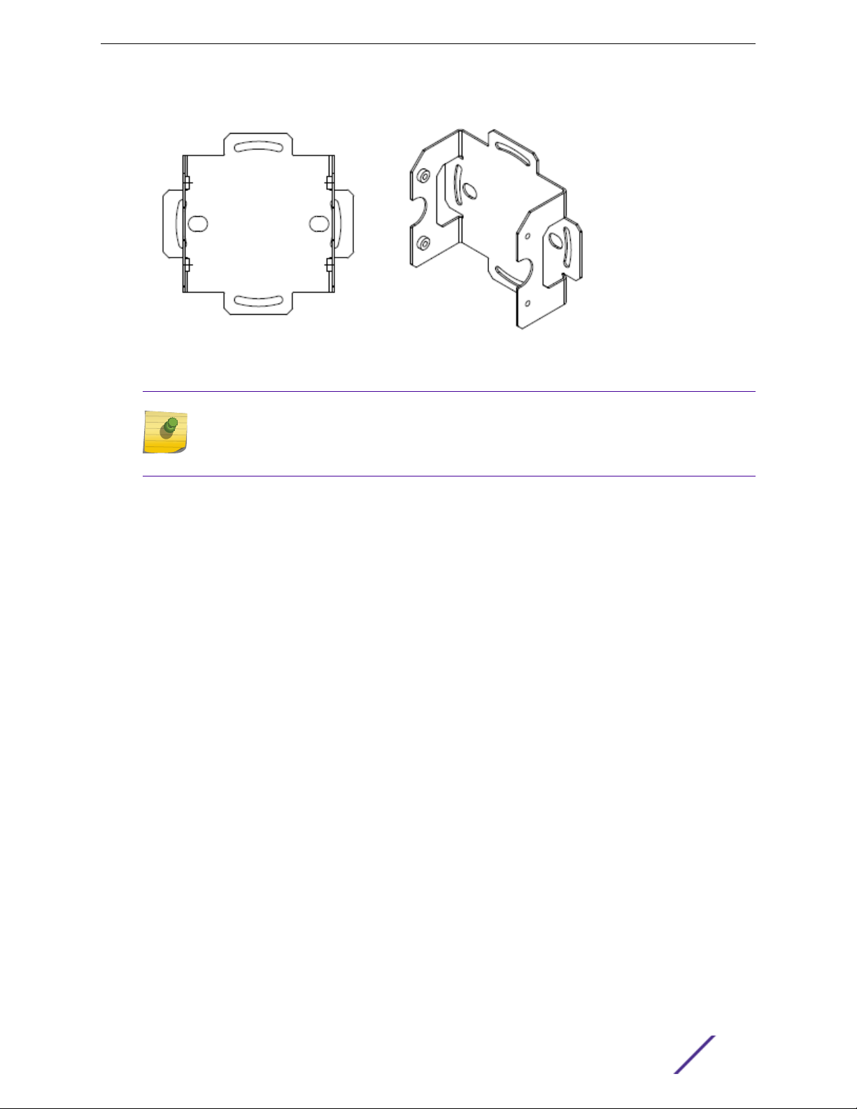
Figure 5: KT-147407-02 bracket 1-axis tilt part
Note
The flat part and the 1-axis tilt part can be used interchangeably with the access points. You
can either attach the flat part or the 1-axis tilt part first and the rest of the installation
procedure will not be aected by it.
Install the Access Point
The following hardware is required:
KT-147407-02 flat part
•
KT-147407-02 1-axis tilt part
•
Access point
•
Ten M6 hex-head screws
•
Two M6 screws to attach the KT-147407-02 flat part to the access point
•
Four M6 screws to attach the KT-147407-02 1-axis tilt part to a flat surface
•
Four M6 screws to attach the KT-147407-02 flat part to the 1-axis tilt part
•
1 Attach the KT-147407-02 flat part to the access point using two M6 hex-head screws.
2 Using the 1-axis tilt part as a template, mark and drill four holes on a wall or a flat surface.
3 Attach the 1-axis tilt part to a wall or a flat surface using four M6 head-size screws.
4 Align the KT-147407-02 flat part bracket inside the 1-axis tilt part, and attach it using four M6 screws.
5 Tilt the access point to a desired angle and tighten the four M6 screws to a torque of 45 in-lbs.
The tilt bracket can be adjusted from +15 degrees to -15 degrees of tilt.
Install the Access Point to a Flat Surface Using the KT-147407-02 Flat Part, 1axis Tilt Part, and the KT- 150173-01 Extension Arm
In installations that require an extension arm, the access point is attached to a flat surface using the
KT-147407-02 bracket parts and the KT-150173-01 extension arm.
ExtremeMobility AP460i/e Outdoor Access Points 15
Page 16

Install the Access Point
Figure 6: KT-150173-01 extension arm
The following hardware is required for installation:
KT-147407-02 flat part
•
KT-147407-02 1-axis tilt part
•
KT-150173-01 extension arm
•
Access point
•
Ten M6 hex-head screws
•
Two M6 hex-head screws to attach the KT-147407-02 flat part to the access point
•
Four M6 hex-head screws to attach the 1-axis tilt part to the flat bracket
•
Four M6 hex-head screws to attach the KT-150173-01 extension arm to a flat surface
•
Two hex-head M12 stainless-steel screws and nuts
•
1 Attach the KT-147407-02 flat part to the access point using two M6 screws.
2 Place the KT-147407-02 flat part inside the 1-axis tilt part, and attach it using four M6 screws.
3 Using the KT-150173-01 extension arm as a template, mark four hole centers on a flat surface.
The holes must be within the semi-circular cuts of the extension arm.
4 Attach one end of the KT-150173-01 extension arm to the 1-axis tilt part using two hex-head M12
stainless-steel screws and two hex-head M12 stainless-steel nuts through the two large circular holes
on the KT-150173- 01 extension arm.
5 Attach the KT-150173-01 extension arm to a flat surface using four M6 size hex-head screws.
Use screw-in anchors with the four M6 size hex-head screws on wood surface.
To mount the extension arm on a concrete surface, use concrete anchors.
ExtremeMobility AP460i/e Outdoor Access Points 16
Page 17

Install the Access Point
Install the Access Point On a Flat Surface Using the KT-150173-01 Extension Arm
For installation for which you don't want to use the KT-147407-02 brackets, you can attach the access
point to a flat surface using just the KT-150173-01 extension arm.
The following hardware is required:
KT-150173-01 extension arm
•
Eight M6 hex-head screws
•
Four M6 hex-head screws to attach one end of the extension arm to the access point
•
Four M6 hex-head screws to attach the other end of the extension arm to the wall
•
Access point
•
1 Using the KT-150173-01 extension arm as a template, mark and drill four hole centers on a flat
surface.
The holes must be within the semi-circular cuts of the extension arm.
2 Attach one end of the KT-150173-01 extension arm to the access point using four M6 screws.
3 Attach the other end of the KT-150173-01 extension arm to the wall using four M6 hex-head screws.
Use screw-in anchors with the four M6 size hex-head screws to mount the bracket on a wood
surface.
To mount the bracket on a concrete surface, use concrete anchors.
Install the Access Point on a Flat Surface Using the MBO-ART02 Articulating Mounting Bracket
The following hardware is required:
MBO-ART02 articulating mounting bracket
•
Access point
•
Six M6 hex-head screws
•
Two M6 hex-head screws is used for attaching the MBO-ART02 articulating mounting bracket to
•
the access point
Four M6 hex-head screws are used for attaching the MBO-ART02 articulating mounting bracket
•
to the wall
ExtremeMobility AP460i/e Outdoor Access Points 17
Page 18

Install the Access Point
1 Using the MBO-ART02 shorter bracket end as a template, mark and drill four holes on the wall.
Figure 7: MBO-ART02 articulating mounting bracket template for wall attachment
holes
2 Attach the MBO-ART02 articulating mounting bracket to the access point using two M6 hex-head
screws.
3 Align the MBO-ART02 articulating mounting bracket holes against the wall attachment holes and
attach the bracket using four M6 hex-head screws.
Install the Access Point on a Flat Surface Using the WS-MBV-VMM Vehicle Bracket (#32216)
To attach the WS-MBV-VMM Vehicle Bracket (#32216) on a flat surface, you can use either the M4 or M6
attachment screws. The bracket has four parts:
Flat plate with thumbscrews; the AP attach assembly plate
•
Stiener plate #1; used with the AP attach assembly plate
•
ExtremeMobility AP460i/e Outdoor Access Points 18
Page 19

Install the Access Point
Stiener plate #2; used with the AP attach assembly plate
•
Vehicle attach assembly plate with PEMS
•
Table 8: WS-MBV-VMM Vehicle Bracket (#32216) box contents
Item Quantity
VMM vehicle attach assembly Vehicle attach plate with PEMS
VMM AP attach assembly AP attach flat plate with stiener #1 and stiener #2
Philips Pan Head M4 (15mm) screws Four screws to attach the AP attach assembly plate to
the access point
The installer must provide the following hardware:
Access point The access point that you are using for installation
Screws or bolts to attach the vehicle attach assembly
plate
Torque wrench/screwdriver Required to attach the screws/bolts and assembly
Four screws or bolts required
plates
1 Using the vehicle assembly plate long inner X slots as a template, mark and drill the attachment
holes on a flat surface.
Figure 8: VMM vehicle attach assembly plate
2 Attach the vehicle attach assembly plate using four screws or bolts.
The screws or bolts must be tightened suciently to hold the bracket and the access point in all
environmental conditions.
ExtremeMobility AP460i/e Outdoor Access Points 19
Page 20

Install the Access Point
3 Align the large holes and assemble both the stiener plates inside the AP attach assembly plate.
Figure 9: VMM access point attach assembly plate stiener #1 and stiener #2
4 Attach four M4 or M6 screws to stiener plate #2 and align the AP's threaded holes to the AP attach
assembly plate.
The screw head goes inside the small bracket with the bent sides.
Note
The bracket comes with four M4 screws.
5 Tighten the screws to 10 in-lbs.
6 Align the AP attach assembly plate to the vehicle attach assembly plate and tighten using four
thumbscrews.
Note
The access point will not be centered and some of the attachment holes in the access
point attach assembly plate will be visible.
Install the Access Point on a Pole
You can install the access point on a pole using the following mounting brackets:
KT-147407-02 bracket parts
•
KT-147407-02 pole part
•
ExtremeMobility AP460i/e Outdoor Access Points 20
Page 21

KT-150173-01 extension arm with the KT-147407-02 pole part
•
KT-150173-01 extension arm with KT-147407-02 bracket parts
•
WS-MBO-POLE01 bracket with the MBO-ART02 articulating mounting bracket
•
Install the Access Point
Figure 10: KT-147407-02 pole part
Note
The pole install options are applicable to both internal and external antenna model outdoor
access points.
ExtremeMobility AP460i/e Outdoor Access Points 21
Page 22

Install the Access Point
Attaching the access point to a pole using all three KT-147407-02 bracket parts
Attach the access point to a pole using all three bracket parts that comes with the KT-147407-02
bracket.
The following hardware is required to mount the access point on to a pole:
Flat part of the KT-147407-02 bracket
•
1-axis tilt part of the KT-147407-02 bracket
•
Pole part of the KT-147407-02 bracket
•
Access point
•
Four M6 hex-head screws
•
Two hex-head M12 stainless-steel screws and nuts
•
Two 0.5" wide stainless-steel cable clamps
•
To attach the access point to a pole:
1 Attach the flat part and the 1-axis tilt part of the KT-147407-02 bracket to the access point. For
instructions on how to attach the bracket parts, see attaching the flat part and the 1-axis tilt part of
the KT-147407-02 bracket to the access point.
2 Attach the pole part of the KT-147407-02 bracket to the 1-axis tilt bracket by using two M12 bolts
through the large bracket holes on the 1-axis tilt bracket and the pole bracket.
Figure 11: Large bracket holes on the 1-axis tilt part of KT-147407-02 bracket
Label
A Large bracket holes used for attaching the M12 screws
ExtremeMobility AP460i/e Outdoor Access Points 22
Description
on the 1-axis tilt part of the KT-147407-02 bracket
Page 23

Install the Access Point
Figure 12: Large bracket holes on the pole part of the KT-147407-02 bracket
Label Description
A Large bracket holes used for attaching the M12 screws
on the pole part of the KT-147407-02 bracket
3 Fasten the M12 screws using two M12 hex nuts.
4 Insert the 0.5" stainless-steel cable clamp through the long slots on the sides of pole bracket.
Figure 13: Long slots on the pole part of the KT-147407-02 bracket
ExtremeMobility AP460i/e Outdoor Access Points 23
Page 24

Install the Access Point
Label Description
A Long slots on the sides of the pole part of the
KT-1474017-02 bracket. These slots are used to insert
the 0.5" stainless-steel cable clamps.
5 Attach the pole bracket to a pole by positioning the cable clamps on the pole bracket around a pole.
6 Insert the ends of the cable clamps around the pole and tighten the clamp screws to a torque of 11
in-lbs.
Attaching the access point to a pole using the pole part of the KT-147407-02 bracket
If the 1-axis tilt is not required, you can attach the pole part of the KT-147407-02 bracket to the access
point.
The following hardware is required:
Pole part of the KT-147407-02 access point
•
Two 0.5" wide stainless-steel cable clamps
•
Access point
•
Four M6 hex-head screws
•
To mount the access point on to a pole using only the pole part of the KT-147407-02 bracket:
1 Attach the pole part of the KT-147407-02 bracket to the access point using four M6 hex-head
screws.
Use the semi-circular cuts on the pole part of the KT-147407-02 bracket to attach the screws.
Figure 14: Semi circular cuts on the pole part of the KT-147407-02 bracket
ExtremeMobility AP460i/e Outdoor Access Points 24
Page 25

Install the Access Point
Label Description
A Semi-circular cuts on the pole part of the
KT-147407-02 bracket, used for attaching the M6 hexhead screws.
2 Insert the 0.5" stainless-steel cable clamp through the long slots on the sides of pole bracket.
3 Attach the pole bracket to a pole by positioning the cable clamps on the pole bracket around a pole.
4 Insert the ends of the cable clamps around the pole and tighten the clamp screws to a torque of 11
in-lbs.
Mounting the access point to a pole using pole part of the KT-147407-02 bracket and the KT-150173-01 extension arm
The access point can be mounted on to a pole using the pole part of the KT-147407-02 bracket and the
KT-150173-01 extension arm.
The following hardware is required:
Pole part of the KT-147407-02 bracket
•
KT-150173-01 extension arm
•
Four M6 hex-head screws
•
Two M12 stainless-steel screws and nuts
•
Two 0.5" stainless-steel cable clamps
•
Access point
•
To install the access point on to a pole:
1 Attach one end of the KT-150173-01 extension arm to the access point using two M6 hex-head
screws.
2 Attach the pole part of the KT-147407-02 bracket to the other end of the KT-150173-01 bracket using
two hex-head M12 stainless-steel screws and two hex-head M12 stainless-steel nuts.
3 Attach the pole bracket to a pole.
Mounting the access point to a pole using the KT-147407-02 bracket parts and the KT-150173-01 extension arm
You can attach the access point to a pole using all the parts of the KT-147407-02 bracket and the
KT-150173-01 extension arm.
The following hardware is required:
Flat part of the KT-147407-02 bracket
•
1-axis tilt part of the KT-147407-02 bracket
•
Pole part of the KT-147407-02 bracket
•
KT-150173-01 extension arm
•
Six M6 hex-head screws
•
Four hex-head M12 stainless-steel screws and nuts
•
ExtremeMobility AP460i/e Outdoor Access Points 25
Page 26

Install the Access Point
Two 0.5" wide stainless-steel cable clamps
•
Access point
•
To install the access point to a pole:
1 Attach the flat part of the KT-147407-02 bracket to the access point. For instruction on how to
attach the bracket parts, see attaching the flat part and the 1-axis tilt part of the KT-147407-02
bracket to the access point.
2 Align the circlular holes on one end of the KT-150173-01 extension arm against the large holes on the
1-axis tilt bracket.
Figure 15: Circular holes on the KT-150173-01 extension arm
Label
A Circular holes on the KT-150173-01 extension arm that
Description
is used to attach to the 1-axis tilt part of the
KT-147407-02 bracket, to attach to the wall, and to
the pole part of the KT-147407-02 bracket.
3 Attach the KT-150173-01 extension arm to the 1-axis tilt bracket by using two hex-head M12 stainless-
steel screws and two hex-head M12 stainless-steel nuts.
4 Attach the pole part of the KT-147407-02 bracket to the other end of the KT-150173-01 extension
arm using two M12 screws and M12 hex-nuts.
5 Insert the 0.5" stainless-steel cable clamps through the long slots on the sides of the KT-147407-02
pole bracket part.
ExtremeMobility AP460i/e Outdoor Access Points 26
Page 27

Install the Access Point
6 Attach the pole bracket to a pole by positioning the cable clamps around a pole.
7 Insert the ends of the cable clamps around the pole and tighten the clamp screws to a torque of 11
in-lbs.
Attaching the access point to a pole using the WS-MBO-POLE01 bracket and MBO-ART02 articulating mounting bracket
The following hardware is required to install the access point to a pole using the WS-MBO-POLE01
bracket and the MBO-ART02 bracket.
WS-MBO-POLE01 bracket
•
MBO-ART02 bracket
•
Two M6 hex-head screws
•
Four M3 screws, nuts, and washers to attach the WS-MBO-POLE01 bracket to the MBO-ART02
•
articulating mounting bracket
Two cable clamps
•
Note
You need to provide your own stainless-steel cable clamps. The band must be 1/2” (12.7
mm) wide.
Access point
•
To mount the access point on to a pole using WS-MBO-POLE01 bracket and the MBO-ART02
articulating mounting bracket:
1 Attach the MBO-ART02 articulating mounting bracket to the access point using two M6 hex-head
screws.
ExtremeMobility AP460i/e Outdoor Access Points 27
Page 28

Install the Access Point
2 Attach the WS-MBO-POLE01 bracket to the MBO-ART02 articulating mounting bracket using four
M3 screws, nuts, and washers.
Figure 16: The POLE01 bracket being attached to the ART02 articulating mounting
bracket
3 Attach both the cable clamps to the WS-MBO-POLE01 bracket.
Open the cable clamp by turning a flat bladed screwdriver counterclockwise. Then insert the non-
clamp end into the pole bracket through the holes.
4 Put the metal band around the pole and attach the WS-MBO-POLE01 bracket to the pole.
ExtremeMobility AP460i/e Outdoor Access Points 28
Page 29

Install the Access Point
5 Tighten the cable clamp screw clockwise, tightening the band around the pole.
Figure 17: Tightening the cable clamp around the pole
ExtremeMobility AP460i/e Outdoor Access Points 29
Page 30

3 Powering method
The AP460i and AP460e access points have one Power over Ethernet (PoE) PD converter that supplies
that main powerto all the downstream.
Table 9: AP460i/e powering method
Power source Description
PoE Power is provided through the RJ45 Ethernet ports of
AP460i/e, compliant to be powered with 802.3at and
802.3bt to provide full functionality. For reduced
functionality, use 802.3af.
ExtremeMobility AP460i/e Outdoor Access Points 30
Page 31

4 GE/Console connections
Installing the cable gland adapter assembly
The AP460i/e access points have two GE (Ethernet) ports and a Console port. During administration
and maintenance through the GE or Console, the access points must still have a power connection
through an Ethernet PoE cable.
For information about the location of the GE and console ports, see AP460i/e features.
Installing the cable gland adapter assembly
Before connecting the RJ45 cable, a waterproof cable gland adapter assembly must be installed onto
the cable.
Figure 18: RJ45 cable gland adapter assembly
Label
1 Sealing nut
2 Claw
3 Seal
4 Main body
Install the cable gland adapter assember onto GE1 or GE2:
ExtremeMobility AP460i/e Outdoor Access Points 31
Description
Page 32

1 Insert the RJ45 cable onto the sealing nut.
GE/Console connections
2 Slide the claw and seal onto the RJ45 cable.
3 Attach the main body into the GE1 or GE2 port of the access point.
ExtremeMobility AP460i/e Outdoor Access Points 32
Page 33

4 Plug the RJ45 cable into the port.
Caution
Do not run the network cable through the cable conduit connector used for connecting
the power cables. You must connect the network cable and power cables through
separate connectors.
5 Slide the seal and the claw into the main body.
6 Secure the seal nut onto the main body.
GE/Console connections
7 Tighten the adapter assembly by hand. Tighten the cap to 5 inch lbs.
Note
There should still be some visible threads after you torque in the cap.
ExtremeMobility AP460i/e Outdoor Access Points 33
Page 34

5 Antenna configuration for external
antenna model
There are extenal antenna connectors on AP460e access point, and it can be configured as described in
the following section.
Figure 19: AP460e external antenna connectors
The 2.4G/5G-8 and the 2.4G/5G-7 are sensor antenna ports.
Note
The internal BLE is always used unless you attach an antenna to the BLE antenna connector.
ExtremeMobility AP460i/e Outdoor Access Points 34
Page 35

Antenna configuration for external antenna model
Note
The BLE antenna port and the sensor antenna ports come with dust caps installed on them.
Do not remove the dust caps until you need to install the antennas.
ExtremeMobility AP460i/e Outdoor Access Points 35
Page 36

6 Specifications
Product specifications
Item Specification
Dimensions AP460i - 7.8" x 9.2" x 2.3" (198mm x 234mm x 59mm)
Housing IP67 rated outdoor use
Available mounting See Access Point Mounting Options, Brackets, and
LEDs Seven
Radios Tri-radio: 2X2:2 2.4GHz, 4X4:4 5GHz, 2X2 sensor
PoE 802.3at (802.3af reduced functionality)
Console port RJ45
Environmental specifications
AP460e - 7.8" x 10.5" x 2.3" (198mm x 268mm x 59mm)
Accessories on page 12.
Item
Operating temperature -40°C to +60°C (-40°F to +140°F) @ 6000 ft.
Operating altitude 6000 ft.
Specifications
ExtremeMobility AP460i/e Outdoor Access Points 36
Page 37

7 Regulatory Information
Professional Installation Instruction
Safety Guidelines
Federal Communications Commission (FCC) Notice
Industry Canada Notice
Detachable Antenna Usage
Australia Notice
Brazil Anatel Statement
Hazardous Substances
Supplement to Product Instructions
NCC Statement
CE Information
European Waste Electrical and Electronic Equipment (WEEE) Notice
Declaration of Conformity in Languages of the European Community
Professional Installation Instruction
Installation personnel
This product is designed for specific application and needs to be installed by a qualified personnel who
has RF and related rule knowledge. The general user shall not attempt to install or change the setting.
External antenna
Use only the antennas which have been approved by the applicant. The non-approved antenna(s) may
produce unwanted spurious or excessive RF transmitting power which may lead to the violation of
FCC/IC limit and is prohibited.
Installation procedure
Refer to the installation instructions for details.
Warning
Select the installation position and make sure that the final output power does not exceed the
limit set force in relevant rules. The violation of the rule could lead to serious federal penalty.
ExtremeMobility AP460i/e Outdoor Access Points 37
Page 38

Regulatory Information
Instructions d'installation professionnelle
Personnel d'installation
Ce produit est conçu pour une application spécifique et doit être installé par un personnel qualifié qui
possède des connaissances sur les RF et les règles associées. L'utilisateur général ne doit pas tenter
d'installer ou de modifier le paramètre.
Antenne externe
Utilisez uniquement les antennes approuvées par le demandeur. Les antennes non approuvées peuvent
produire une puissance de transmission RF parasite ou excessive indésirable, ce qui peut entraîner la
violation de la limite FCC / IC et est interdite.
Procédure d'installation
Reportez-vous aux instructions d'installation pour plus de détails.
Warning
Sélectionnez la position d'installation et assurez-vous que la puissance de sortie finale ne
dépasse pas la force définie dans les règles appropriées. La violation de la règle pourrait
entraîner de graves sanctions fédérales.
Safety Guidelines
The following safety guidelines are intended to protect your personal safety and prevent damage to the
equipment.
Attention
Only qualified personnel should perform installation procedures. Within the context of the
safety notes in this documentation, qualified persons are defined as persons who are
authorized to commission, ground and label devices, systems, and circuits in accordance with
established safety practices and standards. A qualified person understands the requirements
and risks involved with installing outdoor electrical equipment in accordance with national
codes.
Federal Communications Commission (FCC) Notice
This equipment has been tested and found to comply with the limits for a Class B digital device,
pursuant to Part 15 of the FCC Rules. These limits are designed to provide reasonable protection against
harmful interference in a residential installation. This equipment generates, uses and can radiate radio
frequency energy and, if not installed and used in accordance with the instructions, may cause harmful
interference to radio communications. However, there is no guarantee that interference will not occur in
a particular installation. If this equipment does cause harmful interference to radio or television
reception, which can be determined by turning the equipment o and on, the user is encouraged to try
to correct the interference by one of the following measures:
Reorient or relocate the receiving antenna.
•
Increase the separation between the equipment and receiver.
•
ExtremeMobility AP460i/e Outdoor Access Points 38
Page 39

Regulatory Information
Connect the equipment into an outlet on a circuit dierent from that to which the receiver is
•
connected.
Consult the dealer or an experienced radio or TV technician for help.
•
Caution
Any changes or modifications not expressly approved by the party responsible for
compliance could void the user's authority to operate this equipment.
This device complies with Part 15 of the FCC Rules. Operation is subject to the following two conditions:
(1) This device may not cause harmful interference, and (2) this device must accept any interference
received, including interference that may cause undesired operation.
This transmitter must not be co-located or operating in conjunction with any other antenna or
transmitter.
This device is restricted to indoor usage only.
Warning
FCC Radiation Exposure Statement: This equipment complies with FCC radiation exposure
limits set forth for an uncontrolled environment. This equipment should be installed and
operated with a minimum distance of 31 cm between the radiator and your body.
Industry Canada Notice
This device complies with ISED’s licence-exempt RSSs. Operation is subject to the following two
conditions: (1) This device may not cause harmful interference, and (2) this device must accept any
interference received, including interference that may cause undesired operation.
Le présent appareil est conforme aux CNR d’ ISED applicables aux appareils radio exempts de licence.
L’exploitation est autorisée aux deux conditions suivantes : (1) le dispositif ne doit pas produire de
brouillage préjudiciable, et (2) ce dispositif doit accepter tout brouillage reçu, y compris un brouillage
susceptible de provoquer un fonctionnement indésirable.
Caution
The device for operation in the band 5150-5250 MHz is only for indoor use to reduce the
potential for harmful interference to co-channel mobile satellite systems.
les dispositifs fonctionnant dans la bande 5150-5250 MHz sont réservés uniquement pour une
utilisation à l’intérieur afin de réduire les risques de brouillage préjudiciable aux systèmes de
satellites mobiles utilisant les mêmes canaux.
Warning
IC Radiation Exposure Statement:
This equipment complies with ISED radiation exposure limits set forth for an uncontrolled
environment. This equipment should be installed and operated with minimum distance of 39
cm between the radiator and your body.
ExtremeMobility AP460i/e Outdoor Access Points 39
Page 40

Regulatory Information
Warning
Déclaration d'exposition aux radiations:
Cet équipement est conforme aux limites d'exposition aux rayonnements ISED établies pour
un environnement non contrôlé. Cet équipement doit être installé et utilisé avec un minimum
de 39 cm de distance entre la source de rayonnement et votre corps.
Detachable Antenna Usage
This radio transmitter [4141B-AP460] has been approved by Innovation, Science and Economic
Development Canada to operate with the antenna types listed below, with the maximum permissible
gain indicated. Antenna types not included in this list that have a gain greater than the maximum gain
indicated for any type listed are strictly prohibited for use with this device.
Le présent émetteur radio [4141B-AP460] a été approuvé par Innovation, Sciences et Développement
économique Canada pour fonctionner avec les types d'antenne énumérés ci-dessous et ayant un gain
admissible maximal d'antenne. Les types d'antennes non inclus dans cette liste qui ont un gain
supérieur au gain maximal indiqué pour tout type listé sont strictement interdits pour une utilisation
avec cet appareil.
Group Brand Model number Antenna type Antenna gain (dBi)
2.4 GHz 5 GHz BLE or thread
1 Extreme ML-2452-
APA2-01
2 Extreme ML-2452-
APA2-02
3 Extreme ML-2452-
HPA5-036
4 Extreme ML-2452-
HPAG4A6-01
5 Extreme ML-2452-
PNA5-01R
6 Extreme ML-2452-
PTA4M4-036
7 Extreme ML-2452-
HPAG5A8-01
8 Extreme WS-AO-
DQ04360N
9 Extreme AI-DQ04360S Omni 5.5 6 -
10 Extreme ML-2452-
SEC6M4-036 /
WS-AIDQ05120
Omni 3.17 4.85 -
Omni 3.17 4.85 -
Omni 3.9 5.7 -
Omni 4 7.3 -
Panel 4.5 5 -
Omni 5 6.6 -
Omni 5 8 -
Omni 5.5 6 -
Panel 6.92 7.23 -
11 Extreme WS-AI-
DE07025
ExtremeMobility AP460i/e Outdoor Access Points 40
Panel 7.5 6.5 -
Page 41

Group Brand Model number Antenna type Antenna gain (dBi)
2.4 GHz 5 GHz BLE or thread
Regulatory Information
12 Extreme ML-2452-
PNA7-01R
13 Extreme WS-AI-
DE10055
14 Extreme ML-2499-
HPA8-01
Panel 1 7.8 10.7 7.8
Panel 2 10.5 7.5 -
Dipole - - 8
Australia Notice
AU co-location MPE Statement
This equipment complies with AU radiation exposure limits set forth for an uncontrolled environment.
This equipment should be installed and operated with minimum distance of 25 cm between the radiator
and your body.
Brazil Anatel Statement
Este produto está homologado pela ANATEL, de acordo com os procedimentos regulamentados pela
Resolução n°. 242/2000 e atende aos requisitos técnicos aplicados.
Este equipamento não tem direito à proteção contra interferência prejudicial e não pode causar
interferência em sistemas devidamente autorizados. Para maiores informações, consulte o site da
ANATEL – www.anatel.gov.br
Hazardous Substances
This product complies with the requirements of Directive 2011/65/EU of the European Parliament and of
the Council of 8 June 2011 on the restriction of the use of certain hazardous substances in electrical and
electronic equipment.
ExtremeMobility AP460i/e Outdoor Access Points 41
Page 42

Supplement to Product Instructions
Regulatory Information
NCC Statement
低功率電波輻射性電機管理辦法 第十二條 經型式認證合格之低功率射頻電機,非經許可,公司、商
號或使用者均不得 擅自變更頻率、加大功率或變更原設計之特性及功能。 第十四條低功率射頻電機
之使用不得影響飛航安全及干擾合法通信;經發現有干擾現 象時,應立即停用,並改善至無干擾時
方得繼續使用。前項合法通信,指依電信法規 定作業之無線電通信。低功率射頻電機須忍受合法通
信或工業、科學及醫療用電波輻 射性電機設備之干擾。 無線資訊傳輸設備避免影響附近雷達系統之
操作。 「本器材須經專業工程人員安裝及設定,始得設置使用,且不得直接販售給一般消費 者」。
CE Information
The device is restricted to indoor use only when operating in the 5150 to 5350 MHz frequency range.
Warning
CE co-location MPE Statement:
This equipment complies with CE radiation exposure limits set forth for an uncontrolled
environment. This equipment should be installed and operated with minimum distance of 20
cm between the radiator and your body.
AT BE BG HR CY CZ DK
EE FI FR DE EL HU IE
IT LV LT LU MT NL PL
PT RO SK SI ES SE UK
ExtremeMobility AP460i/e Outdoor Access Points 42
Page 43

All operational modes:
Frequency AP460i AP460e
Regulatory Information
2.4GHz 802.11b, 802.11g, 802.11n (HT20),
802.11n (HT40), 802.11ax (HEW20),
802.11ax (HEW40), 802.15.4
(Thread), Bluetooth (LE)
5GHz 802.11a, 802.11n (HT20), 802.11n
(HT40), 802.11ac (VHT20), 802.11ac
(VHT40), 802.11ac (VHT80), 802.11ac
(VHT160), 802.11ax (HEW20),
802.11ax (HEW40), 802.11ax
(HEW80), 802.11ax (HEW160)
802.11b, 802.11g, 802.11n (HT20),
802.11n (HT40), 802.11ac (VHT20),
802.11ac (VHT40), Bluetooth (BR/
EDR, LE)
802.11a, 802.11n (HT20), 802.11n
(HT40), 802.11ac (VHT20), 802.11ac
(VHT40), 802.11ac (VHT80), 802.11ac
(VHT160)
The frequency and the maximum transmitted power in EU are listed below:
Frequency Maximum transmitted power
(AP460i)
2412-2472MHz 19.98 dBm 20 dBm
2402-2480MHz (BR/EDR) N/A 6 dBm
2402-2480MHz (LE) 6.23 dBm 8 dBm
5180-5240MHz 22.98 dBm 23 dBm
5260-5320MHz 22.98 dBm 23 dBm
5500-5700MHz 29.98 dBm 30 dBm
Maximum transmitted power
(AP460e)
2405-2480MHz 6.48 dBm N/A
European Waste Electrical and Electronic Equipment (WEEE) Notice
In accordance with Directive 2012/19/EU of the European Parliament on waste electrical and electronic
equipment (WEEE):
1 The symbol above indicates that separate collection of electrical and electronic equipment is
required.
2 When this product has reached the end of its serviceable life, it cannot be disposed of as unsorted
municipal waste. It must be collected and treated separately.
ExtremeMobility AP460i/e Outdoor Access Points 43
Page 44

Regulatory Information
3 It has been determined by the European Parliament that there are potential negative eects on the
environment and human health as a result of the presence of hazardous substances in electrical and
electronic equipment.
4 It is the user's responsibility to utilize the available collection system to ensure WEEE is properly
treated.
For information about the available collection system, please contact Extreme Environmental
Compliance at Green@extremenetworks.com.
Declaration of Conformity in Languages of the European Community
English Hereby, Extreme Networks, declares that the radio
equipment type (AP460i/e) is in compliance with
Directive 2014/53/EU. For full text of the EU
Deceleration of Conformity, please contact Extreme
Regulatory Compliance at
compliancerequest@extremenetworks.com
Finnish Valmistaja Extreme Networks vakuuttaa täten että
Radio LAN device (AP460i/e) tyyppinen laite on
direktiivin 2014/53/EU oleellisten vaatimusten ja sitä
koskevien direktiivin muiden ehtojen mukainen.
Täydellinen teksti EU: n vaatimustenmukaisuuden
hidastumisesta, ota yhteyttä Extreme Regulatory
Complianceyn osoitteessa
compliancerequest@extremenetworks.com
Dutch Hierbij verklaart Extreme Networks dat het toestel
Radio LAN device (AP460i/e) in overeenstemming is
met de essentiële eisen en de andere relevante
bepalingen van richtlijn 2014/53/EU. Neem voor een
volledige tekst van de EU Deceleration of Conformity
contact op met Extreme Regulatory Compliance op
compliancerequest@extremenetworks.com
French Par la présente Extreme Networks déclare que l'appareil
Radio LAN device (AP460i/e) est conforme aux
exigences essentielles et aux autres dispositions
pertinentes de la directive 2014/53/EU. Pour obtenir le
texte intégral du processus de décélération de la
conformité de l'UE, veuillez contacter la conformité
réglementaire extrême à l'adresse suivante:
compliancerequest@extremenetworks.com
Swedish Härmed intygar Extreme Networks överensstämmelse
med de väsentliga egenskapskrav och övriga relevanta
bestämmelser som framgår av direktiv 2014/53/ EU. För
fullständig text om EU-deceleration av
överensstämmelse, vänligen kontakta Extreme
Regulatory Compliance på
compliancerequest@extremenetworks.com
ExtremeMobility AP460i/e Outdoor Access Points 44
Page 45

Regulatory Information
Danish Undertegnede Extreme Networks erklærer herved, at
følgende udstyr Radio LAN device (AP460i/e)
overholder de væsentlige krav og øvrige relevante krav i
direktiv 2014/53/EU. For fuld tekst af EU's deceleration
of Conformity, kontakt venligst Extreme Regulatory
Compliance på
compliancerequest@extremenetworks.com
German Hiermit erklärt Extreme Networks die Übereinstimmung
des "WLAN Wireless Controller bzw. Access Points"
(AP460i/e) mit den grundlegenden Anforderungen und
den anderen relevanten Festlegungen der Richtlinie
2014/53/EU. Den vollständigen Text der EUKonformitätsverzögerung erhalten Sie von Extreme
Regulatory Compliance unter
compliancerequest@extremenetworks.com
Greek ΜΕ ΤΗΝ ΠΑΡΟΥΣΑ Extreme Networks ΔΗΛΩΝΕΙ ΟΤΙ
Radio LAN device (AP460i/e) ΣΥΜΜΟΡΦΩΝΕΤΑΙ
ΠΡΟΣ ΤΙΣ ΟΥΣΙΩΔΕΙΣ ΑΠΑΙΤΗΣΕΙΣ ΚΑΙ ΤΙΣ ΛΟΙΠΕΣ
ΣΧΕΤΙΚΕΣ ΔΙΑΤΑΞΕΙΣ ΤΗΣ ΟΔΗΓΙΑΣ 2014/53/EU.
Για το πλήρες κείμενο της Σταθμιστικής Συμμόρφωσης της
ΕΕ, επικοινωνήστε με την Extreme Regulatory
Compliance στη διεύθυνση
compliancerequest@extremenetworks.com
Icelandic Extreme Networks lysir her med yfir að thessi bunadur,
Radio LAN device (AP460i/e), uppfyllir allar
grunnkrofur, sem gerdar eru i R&TTE tilskipun ESB nr
2014/53/EU. Vinsamlegast hafið samband við Extreme
Regulatory Compliance í
compliancerequest@extremenetworks.com fyrir fullan
texta af samruna Evrópusamningsins.
Italian Con la presente Extreme Networks dichiara che questo
Radio LAN device (AP460i/e) è conforme ai requisiti
essenziali ed alle altre disposizioni pertinenti stabilite
dalla direttiva 2014/53/EU. Per il testo completo della
Decelerazione di conformità UE, contattare Extreme
Compliance Regulatory all'indirizzo
compliancerequest@extremenetworks.com
Spanish Por medio de la presente Extreme Networks declara
que el Radio LAN device (AP460i/e) cumple con los
requisitos esenciales y cualesquiera otras disposiciones
aplicables o exigibles de la Directiva 2014/53/EU. Para
obtener el texto completo de la desaceleración de la
conformidad de la UE, comuníquese con Extreme
Regulatory Compliance en
compliancerequest@extremenetworks.com
ExtremeMobility AP460i/e Outdoor Access Points 45
Page 46

Regulatory Information
Portuguese Extreme Networks declara que este Radio LAN device
(AP460i/e) está conforme com os requisitos essenciais
e outras disposições da Directiva 2014/53/EU. Para
obter o texto completo da desaceleração de
conformidade da UE, entre em contato com a Extreme
Regulatory Compliance em
compliancerequest@extremenetworks.com
Malti Hawnhekk, Extreme Networks, jiddikjara li dan Radio
LAN device (AP460i/e) jikkonforma mal-htigijiet
essenzjali u ma provvedimenti ohrajn relevanti li hemm
fid-Dirrettiva 2014/53/EU. Għal test sħiħ tadDeċellerazzjoni tal-Konformità tal-UE, jekk jogħġbok
ikkuntattja l-Konformità Regolatorja Estrema fi
compliancerequest@extremenetworks.com
ExtremeMobility AP460i/e Outdoor Access Points 46
Page 47

Index
A
Antenna Configurations
AP460e access point antenna connectors 34
AP460i/e mounting options
accessories 12
optional brackets 12
pole install 12
wall install 12
AP460i/e Power Source 30
Australia notice 41
B
box contents
AP460e contents 12
AP460i contents 12
C
conventions
notice icons 4
text 4
D
documentation
feedback 5
location 6
F
FCC notice 38
features
AP460e features 7
AP460i features 7
Flat surface install
MBO-ART02 mounting bracket 17
Flat surface installation
KT-147407-02 bracket 15
KT-150173-01 extension arm 17
G
GE and Console Connections 31
GE1/GE Connection
Cable gland assembly 31
installation procedure (continued)
wall Install 14
K
KT-147407-02 pole mounting
Pole part of the KT-147407-02 bracket 24
L
LED
LED indicators 9
M
Mounting option
Pole Mounting 20
Mounting Option
VMM bracket installation 18
N
NCC statement 42
O
Open Source Declaration 6
overview
AP460e 7
AP460i 7
firmware use 7
P
Pole Install
POLE01 bracket and the ART02 bracket 27
Pole mounting
KT-147407-02 bracket parts 22
KT-147407-02 pole part 25
KT-150173-01 extension arm 25
Pole Mounting
KT-150173-01 extension arm and all KT-147407-02
bracket parts 25
professional installation instruction 37
purchase order information
AP460e ordering information 11
AP460i ordering information 11
I
install the access point
AP460e box contents 12
AP460e installation 12
AP460i box contents 12
AP460i installation 12
installation procedure
flat Surface install 14
ExtremeMobility AP460i/e Outdoor Access Points 47
R
Regulatory Information 42
Regulatory Information, Hazardous Substances 41
S
safety guidelines 38
Page 48

Specifications
Environmental Specifications 36
Product Specifications 36
support, see technical support
T
technical support
contacting 5
Index
ExtremeMobility AP460i/e Outdoor Access Points 48
 Loading...