

Page 1

ExtremeWireless™ WSAP3825i & WS-AP3825e
Installation Guide
9034791-02
Published September 2016
Page 2

Copyright © 2016 Extreme Networks, Inc. All rights reserved.
Legal Notice
Extreme Networks, Inc. reserves the right to make changes in specifications and other information
contained in this document and its website without prior notice. The reader should in all cases
consult representatives of Extreme Networks to determine whether any such changes have been
made.
The hardware, firmware, software or any specifications described or referred to in this document
are subject to change without notice.
Trademarks
Extreme Networks and the Extreme Networks logo are trademarks or registered trademarks of
Extreme Networks, Inc. in the United States and/or other countries.
All other names (including any product names) mentioned in this document are the property of
their respective owners and may be trademarks or registered trademarks of their respective
companies/owners.
For additional information on Extreme Networks trademarks, please see:
www.extremenetworks.com/company/legal/trademarks
Support
For product support, including documentation, visit: http://www.extremenetworks.com/support/
For information, contact:
Extreme Networks, Inc.
145 Rio Robles
San Jose, California 95134
USA
Page 3

Table of Contents
Preface.........................................................................................................................................4
Text Conventions...................................................................................................................................................................4
Providing Feedback to Us................................................................................................................................................ 4
Getting Help.............................................................................................................................................................................5
Related Publications............................................................................................................................................................5
Chapter 1: About This Guide.....................................................................................................6
Who Should Use This Guide............................................................................................................................................6
How to Use This Guide.......................................................................................................................................................6
Chapter 2: Introduction.............................................................................................................7
About the WS-AP3825i and WS-AP3825e..............................................................................................................7
WS-AP3825 Overview........................................................................................................................................................ 7
Architectural Features.......................................................................................................................................................12
Chapter 3: Installation..............................................................................................................14
Unpacking the WS-AP3825........................................................................................................................................... 14
Accessories.............................................................................................................................................................................14
Access Point Installation Procedures.........................................................................................................................14
Configuring AP Channel Settings...............................................................................................................................25
Appendix A: Specifications....................................................................................................30
External Power Supplies.................................................................................................................................................30
Internal Antenna Access Points....................................................................................................................................31
External Antennas..............................................................................................................................................................37
Appendix B: Regulatory Information....................................................................................39
ExtremeWireless WS-AP3825i and WS-AP3825e.............................................................................................39
ExtremeWireless™ WS-AP3825i & WS-AP3825e Installation Guide for version . 3
Page 4
Preface
Text Conventions
The following tables list text conventions that are used throughout this guide.
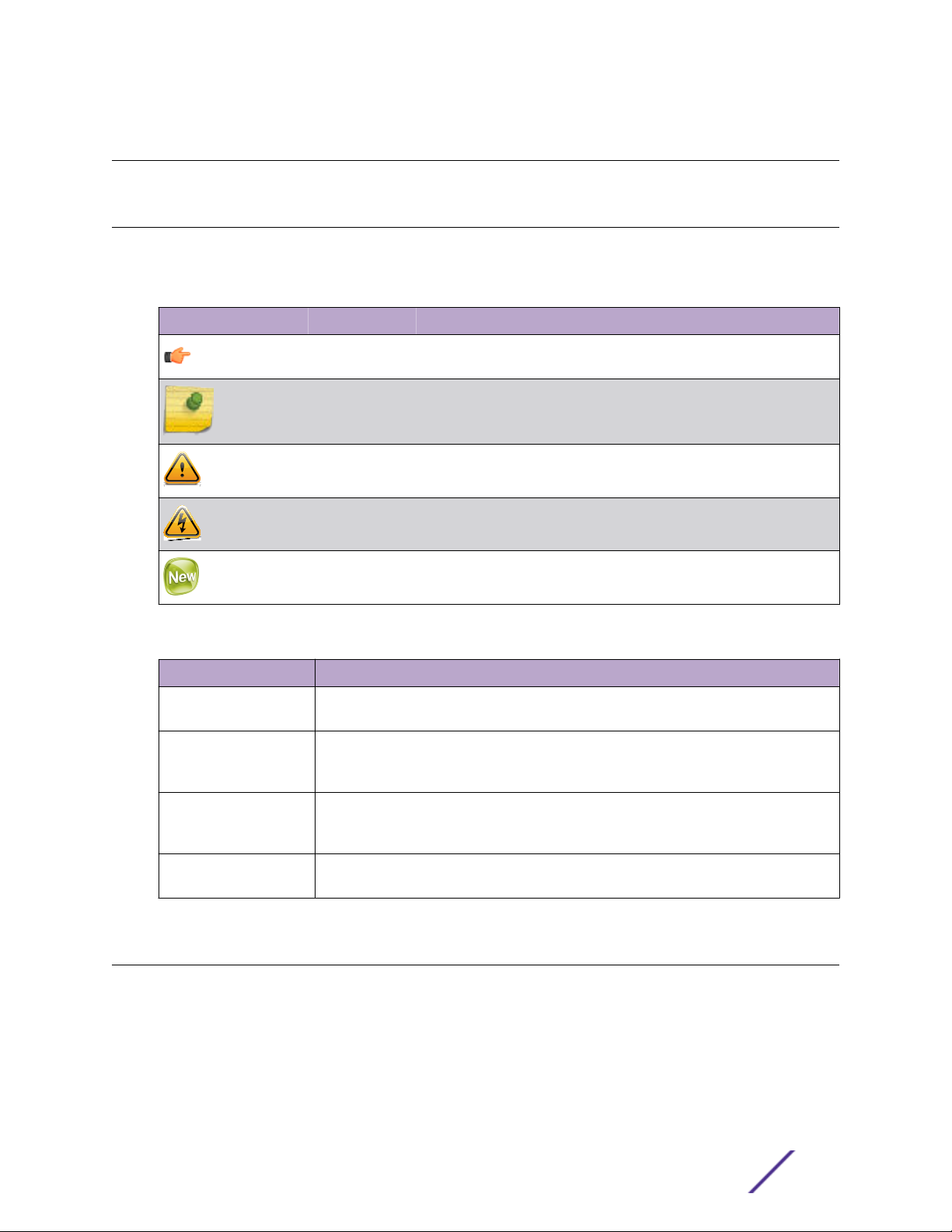
Table 1: Notice Icons
Icon Notice Type Alerts you to...
General Notice Helpful tips and notices for using the product.
Note Important features or instructions.
Caution Risk of personal injury, system damage, or loss of data.
Warning Risk of severe personal injury.
New This command or section is new for this release.
Table 2: Text Conventions
Convention Description
Screen displays
The words enter and
type
[Key] names Key names are written with brackets, such as [Return] or [Esc]. If you must press two
Words in italicized type Italics emphasize a point or denote new terms at the place where they are defined in
This typeface indicates command syntax, or represents information as it appears on the
screen.
When you see the word “enter” in this guide, you must type something, and then press
the Return or Enter key. Do not press the Return or Enter key when an instruction
simply says “type.”
or more keys simultaneously, the key names are linked with a plus sign (+). Example:
Press [Ctrl]+[Alt]+[Del]
the text. Italics are also used when referring to publication titles.
Providing Feedback to Us
We are always striving to improve our documentation and help you work better, so we want to hear
from you! We welcome all feedback but especially want to know about:
Content errors or confusing or conflicting information.
•
Ideas for improvements to our documentation so you can find the information you need faster.
•
Broken links or usability issues.
•
ExtremeWireless™ WS-AP3825i & WS-AP3825e Installation Guide for version . 4
Page 5

If you would like to provide feedback to the Extreme Networks Information Development team about
this document, please contact us using our short online feedback form. You can also email us directly at
internalinfodev@extremenetworks.com.
Getting Help
If you require assistance, contact Extreme Networks using one of the following methods:
Global Technical Assistance Center (GTAC) for Immediate Support
•
Phone: 1-800-998-2408 (toll-free in U.S. and Canada) or +1 408-579-2826. For the support
•
phone number in your country, visit: www.extremenetworks.com/support/contact
Email: support@extremenetworks.com. To expedite your message, enter the product name or
•
model number in the subject line.
GTAC Knowledge — Get on-demand and tested resolutions from the GTAC Knowledgebase, or
•
create a help case if you need more guidance.
The Hub — A forum for Extreme customers to connect with one another, get questions answered,
•
share ideas and feedback, and get problems solved. This community is monitored by Extreme
Networks employees, but is not intended to replace specific guidance from GTAC.
Support Portal — Manage cases, downloads, service contracts, product licensing, and training and
•
certifications.
Preface
Before contacting Extreme Networks for technical support, have the following information ready:
Your Extreme Networks service contract number and/or serial numbers for all involved Extreme
•
Networks products
A description of the failure
•
A description of any action(s) already taken to resolve the problem
•
A description of your network environment (such as layout, cable type, other relevant environmental
•
information)
Network load at the time of trouble (if known)
•
The device history (for example, if you have returned the device before, or if this is a recurring
•
problem)
Any related Return Material Authorization (RMA) numbers
•
Related Publications
ExtremeWireless and ExtremeWireless AP documentation can be found on the Extreme Documentation
page at: http://documentation.extremenetworks.com
The ExtremeWireless User Guide is recommended.
ExtremeWireless™ WS-AP3825i & WS-AP3825e Installation Guide for version . 5
Page 6
1 About This Guide
Who Should Use This Guide
How to Use This Guide
The guide describes how to mount and connect cables to the ExtremeWireless™ AP3825 access point. In
addition, this guide provides information on the product certifications and national approvals for the
WS-AP3825 access point.
Note
This guide does not provide information on configuration of the access points. For
information on how to configure the access points, see the ExtremeWireless User Guide.
Who Should Use This Guide
Warning
Electrical Hazard: Only qualified personnel should install or service this unit.
Riesgo Electrico: Nada mas personal capacitado debe de instalar o darle servicio a esta unida.
Elektrischer Gefahrenhinweis: Installationen oder Servicearbeiten sollten nur durch
ausgebildetes und qualifiziertes Personal vorgenommen werden.
How to Use This Guide
Read through this guide completely to familiarize yourself with its contents and to gain an
understanding of the features and capabilities of the WS-AP3825 access point. A general working
knowledge of data communications networks is helpful when setting up this product.
ExtremeWireless™ WS-AP3825i & WS-AP3825e Installation Guide for version . 6
Page 7

2 Introduction
About the WS-AP3825i and WS-AP3825e
WS-AP3825 Overview
Architectural Features
About the WS-AP3825i and WS-AP3825e
The WS-AP3825i and WS-AP3825e access points are a cost-eective solution for extending your
wireless LAN around indoor locations. They interoperate fully with the Extreme Networks wireless LAN,
including support for Extreme Networks wireless VoWLAN, branch oce mode, availability, and
mobility features.
The WS-AP3825i and WS-AP3825e are nearly identical in appearance and have the following features in
common:
Both operate in 802.11ac and 802.11n mode and also support 802.11a/802.11g and 802.11b standard
•
legacy devices.
Both support two MIMO 3x3 (up to three 802.11ac spatial streams).
•
They provide two single-band radios for dual-band, concurrent operation, optimized for indoor
•
antenna coverage:
5 GHz (Radio 1) in any of the following modes: IEEE802.11ac, a/b/g and/or n
•
2.4 GHz (Radio 2) in any of the following modes: IEEE802.11ac, a/b/g and/or n
•
They are enclosed in a rectangular, compact case.
•
Both models include two mounting brackets, and screws/anchors, for mounting them to walls and
•
drop/suspended ceilings.
They provide 40MHz Bandwidth at 2.4/5 GHz operation (Channel Bonding).
•
They can be powered directly through the LAN using Power over Ethernet (PoE), or by an external
•
110/240V AC/DC adaptor.
Both have dual Ethernet (LAN) ports for fault-tolerant network connection and failover.
•
Note
The WS-AP3825 comes in two models: the WS-AP3825i has six internal single-band antennas
while the WS-AP3825e has six external RSMA connectors for connecting external antennas.
Within this document, any reference to WSAP3825 applies to both models.
WS-AP3825 Overview
The WS-AP3825 access point is available in two models:
WS-AP3825i contains six internal single-band antennas
•
WS-AP3825e contains six external RSMA connectors for optional external antennas, for greater
•
range and coverage versatility
ExtremeWireless™ WS-AP3825i & WS-AP3825e Installation Guide for version . 7
Page 8
Introduction
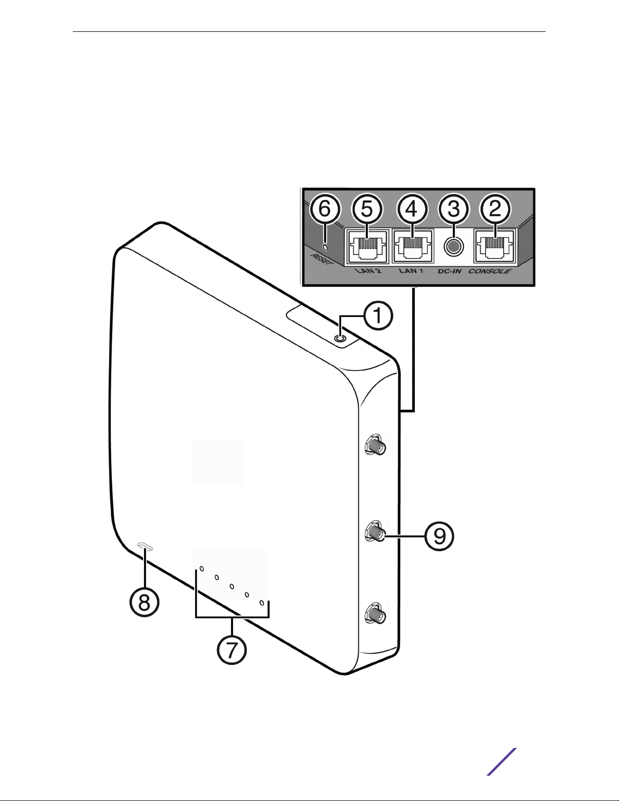
Figure 1 shows the front view of the WS-AP3825i and Figure 2 on page 9 shows the front view of the
WS-AP3825e. Both figures also show the location of the LAN ports, console port, external power supply
connector, and reset switch.
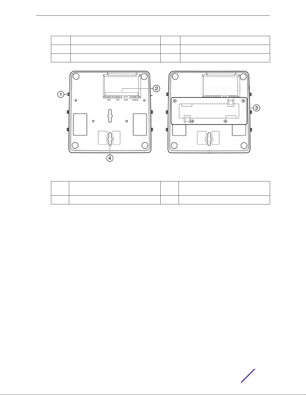
Figure 3 on page 10 shows the back view of the WS-AP3825e. The back panel is the same for both
models, but there are no external antenna RSMA connectors on the WS-AP3825i.
Figure 4 on page 11 illustrates the WS-AP3825 LEDs.
Figure 1: Extreme Networks Wireless AP3825i Front View
ExtremeWireless™ WS-AP3825i & WS-AP3825e Installation Guide for version . 8
Page 9
Introduction
1 (not used) 5 LAN port 2
2 Console port 6 Reset switch
3 External power supply port 7 LEDs (See Figure 4 on page 11 for details)
4 LAN port 1 8 (bottom) Slot for Kensington lock
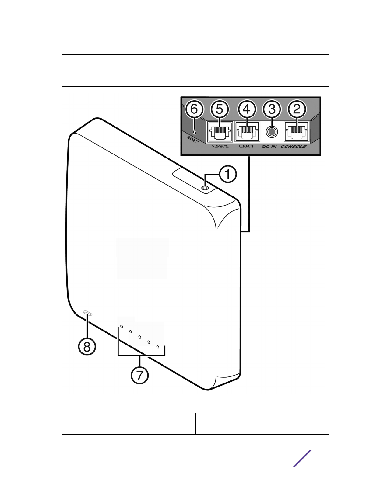
Figure 2: Extreme Networks Wireless AP3825e Front View
1
2 Console port 7 LEDs (See Figure 4 on page 11 for details)
ExtremeWireless™ WS-AP3825i & WS-AP3825e Installation Guide for version . 9
(not used) 6 Reset switch
Page 10
Introduction
3 External power supply port 8 (bottom) Slot for Kensington lock
4 LAN port 1 9 RSMA External antenna connectors (6)
5 LAN port 2 10
Figure 3: WS-AP3825 Back View
1
2 Port Bay 4 Mounting Slot
RSMA antenna connectors (WS-AP3825e
only)
3 Mount Bracket
WS-AP3825 LED Indicators
Both models of the WS-AP3825 have four LED indicators, shown in Figure 4 below. The LEDs provide
status information, described in Table 1-1, on the current state of the WS-AP3825. For more information,
see the ExtremeWireless User Guide.
ExtremeWireless™ WS-AP3825i & WS-AP3825e Installation Guide for version . 10
Page 11
Introduction
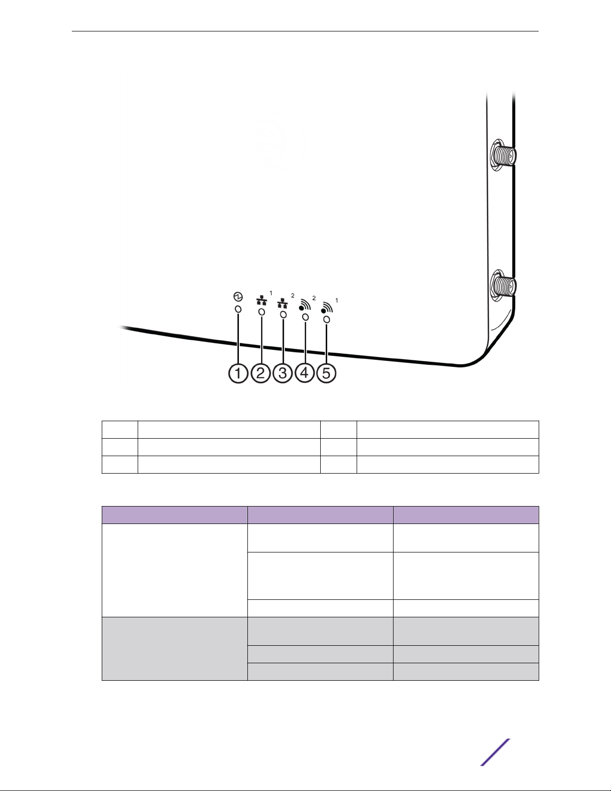
Figure 4: WS-AP3825 LEDs (Front, lower right)
1
2 LAN 1 (Ethernet 1) link state 5 Radio 1 status (5 GHz)
3 LAN 2 (Ethernet 2) link state
AP status 4 Radio 2 status (2.4 GHz)
Table 3: WS-AP3825 LED Indications
LED Status Description
1 (AP status) On Green Indicates the WS-AP3825 is working
normally.
Flashing Green Indicates:
running a self test
•
loading software program
•
On Amber Indicates a CPU/system failure.
2 (Ethernet link state) LAN 1 On Green Indicates a valid 100Mbps Ethernet
link.
On Amber Indicates a valid 1Gbps Ethernet link.
O Indicates the link is down.
ExtremeWireless™ WS-AP3825i & WS-AP3825e Installation Guide for version . 11
Page 12
Table 3: WS-AP3825 LED Indications (continued)
LED Status Description
3 (Ethernet link state) LAN 2 On Green Indicates a valid 100Mbps Ethernet
On Amber Indicates a valid 1Gbps Ethernet link.
O Indicates the link is down.
4 (Radio 2 status) On Green Indicates Radio 2 is enabled.
O Indicates Radio 2 is not on.
5 (Radio 1 status) On Green Indicates Radio 1 is enabled.
O Indicates Radio 1 is not on.
Architectural Features
Introduction
link.
Console Port
The WS-AP3825 i and e models both include a single RJ45 console port (shown in Figure 1 on page 8
and Figure 2 on page 9) for debug purposes. This port enables connection of a console device to the AP
through a serial cable. The console device can be a PC or workstation running a VT-100 terminal adapter
emulator, or a VT-100 terminal.
LAN Port
The WS-AP3825 has two 10/100/1000BaseT RJ45 LAN ports (see Figure 1 on page 8) that can be
attached directly to a 10/100/1000BaseT LAN segment. This segment must conform to the IEEE 802.3
or 802.3u specifications.
The APs appear as Ethernet nodes and perform a bridging function by moving packets from the wired
LAN to remote workstations on the wireless infrastructure.
The LAN ports also support power over Ethernet (PoE) based on the IEEE 802.3af standard. Refer to
Installation on page 14, for information on supplying power to the AP network port from a network
device, such as a switch, that provides Power over Ethernet (PoE).
Reset Switch
The WS-AP3825 provides a Reset Switch to reset or restore factory default configurations. Use a pen tip
or a nail to press the switch button through the hole (located on the top side of the AP). If you hold
down the button for less than 5 seconds, the AP performs a software interrupt, causing it to drop all
connections and reset. If you hold the button down for 5 seconds or more, any configuration changes
are removed, and the factory default configuration restores to the AP.
ExtremeWireless™ WS-AP3825i & WS-AP3825e Installation Guide for version . 12
Page 13

Kensington Lock Slot
There is a slot for a Kensington lock on the bottom side of the AP. See Kensington lock documentation
for instructions on use of the lock.
Introduction
ExtremeWireless™ WS-AP3825i & WS-AP3825e Installation Guide for version . 13
Page 14
3 Installation
Unpacking the WS-AP3825
Accessories
Access Point Installation Procedures
Configuring AP Channel Settings
Unpacking the WS-AP3825
To unpack the access point:
1 Open the box and remove the packing material protecting the AP.
2 Verify that the carton contains the items listed below.
Table 4: WS-AP3825 Package Contents
Quantity Item
1 WS-AP3825
2 Mounting brackets with screws
2 Wall mounting screws and plastic anchors
1 WS-AP3825 Quick Reference card
3 Perform a visual inspection of the AP for any signs of physical damage. Contact Extreme Networks if
there are any signs of damage. Refer to Getting Help on page 5 for details.
Accessories
The following accessories are available for the ExtremeWireless WS-AP3825. For ordering information,
contact your Extreme Networks sales representative.
12V DC power supply (see External Power Supplies on page 30)
•
External antennas (WS-AP3825e models only; See External Antennas on page 37)
•
Access Point Installation Procedures
Warning
Electrical Hazard: Only qualified personnel should install or service this unit.
Riesgo Electrico: Nada mas personal capacitado debe de instalar o darle servicio a esta unida.
Elektrischer Gefahrenhinweis: Installationen oder Servicearbeiten sollten nur durch
ausgebildetes und qualifiziertes Personal vorgenommen werden.
These procedures describe how to attach the WS-AP3825 to a drop ceiling (flat or protruded), and how
to mount the AP to a wall.
ExtremeWireless™ WS-AP3825i & WS-AP3825e Installation Guide for version . 14
Page 15
Mounting the WS-AP3825 to a Drop Ceiling
To mount the AP to a drop ceiling, use one of the mounting brackets provided with the AP. There are
brackets for flat drop ceilings and protruded drop ceilings.
Flat Drop Ceiling Bracket
•
Flat drop ceilings are those in which the ceiling tiles rest flat (or nearly so) on their supporting T-bar
rails. The flat drop ceiling bracket has a low flat profile, to mount the AP close against the T-bar rail.
Installation
Protruded Drop Ceiling Bracket
•
Protruded drop ceilings are those in which the ceiling tiles protrude well beyond the T-bar rails on
which they rest. The protruded drop ceiling bracket has an extended mount plate, allowing the AP to
hang below the protruded ceiling tiles.
Note
We recommend that the first time you mount an AP3825 to a drop ceiling T-bar rail, you try
mounting the bracket to a rail before attaching it to the back of an AP and mounting the AP
to the rail. This way you can get the “feel” of the tilt and twist motion described in step 3 on
page 17 in the procedure below, to make the bracket tabs clear the rail and slide over the rail
lip on both sides.
To attach the WS-AP3825 to a drop ceiling:
ExtremeWireless™ WS-AP3825i & WS-AP3825e Installation Guide for version . 15
Page 16

Installation
1 Attach the T-bar rail mount bracket to the back of the AP by placing the bracket against the AP
back, aligned as shown in Figure 5, with the bracket’s countersink screw holes matched up with the
screw holes on the AP. Screw the provided screws into the mounting bracket and AP as shown in
Figure 5.
Figure 5: Attaching a Mount Bracket to the AP back
2 Remove the ceiling panels around the drop ceiling T-bar rails where you intend to mount the AP.
Verify that the Ethernet cable that will connect to the AP can reach the AP at the point where you
plan to mount it.
ExtremeWireless™ WS-AP3825i & WS-AP3825e Installation Guide for version . 16
Page 17

Installation
3 Hold the AP with the bracket against the flat side of the T-bar rail and (nearly) parallel to it. The
clamping tabs fit over the rail easily if you slide one bracket tab over the lip of the rail, at a very slight
angle to the rail, and then press the AP up against the rail (so that the opposite clamping tab clears
the rail) and twist it so that the opposite clamping tab slides over the opposite rail lip as shown in
Figure 6. There are flex tabs immediately opposite each bracket tab, that flex out (away from the
rail) to stabilize the bracket against the rail while you pivot the AP and bracket to clear the rail.
Figure 6: Mounting the Bracket to the Ceiling Rail
ExtremeWireless™ WS-AP3825i & WS-AP3825e Installation Guide for version . 17
Page 18

Installation
4 When the bracket is aligned with the rail again, both clamping tabs are positioned on the T-bar rail
lips. Figure 7 shows a mounting bracket, with an AP attached, firmly mounted on a drop-ceiling Tbar rail. Tap the AP to verify it is stable and won't fall o.
Figure 7: AP and Mounting Bracket Seated on T-bar Rail
5 Make a hole through the ceiling panel closest to the connector bay on the AP. Then run the Ethernet
cable through the hole and into a LAN port (RJ45 Ethernet port) in the connector bay.
6 Replace the displaced ceiling panels.
Mounting the WS-AP3825 to a Wall or Solid Ceiling
Screws for attaching the AP to a wall or solid ceiling are supplied with the product. Use the following
procedure to mount the AP3825 to a flat wall.
1 Determine the spot where the AP is to be mounted, preferably high up on the wall (near the ceiling
for maximum radio wave dispersion) but in reach of the Ethernet cable and a wall power outlet if
you are not able to use Power over Ethernet.
ExtremeWireless™ WS-AP3825i & WS-AP3825e Installation Guide for version . 18
Page 19

Installation
2 Drill two holes in the wall to match the center of the two keyhole slots in the back of the AP. The
location of the holes is depicted in Figure 8 (measurements are in millimeters). For a tight fit, the
holes should be slightly smaller than the diameter of the provided plastic anchors.
Figure 8: Drilling Template for Wall Mounting
3 Tap the plastic anchors into the holes with a hammer until they are flush with the wall, and screw the
provided mounting screws into the anchors, with the head protruding 1/16" from the anchor.
ExtremeWireless™ WS-AP3825i & WS-AP3825e Installation Guide for version . 19
Page 20

Installation
4 Place the back of the AP against the wall with the protruding mounting screw heads fitting through
the keyhole slots on the back of the AP, and slide the AP down until the AP rests on the mounting
screw heads. Figure 9 shows an exploded view of this mounting method.
Figure 9: Mounting the WS-AP3825 to a Flat Wall or Solid Ceiling
5 Plug the Ethernet cable into the RJ-45 port (and plug the power cord into the power port, if
applicable) on the back of the AP.
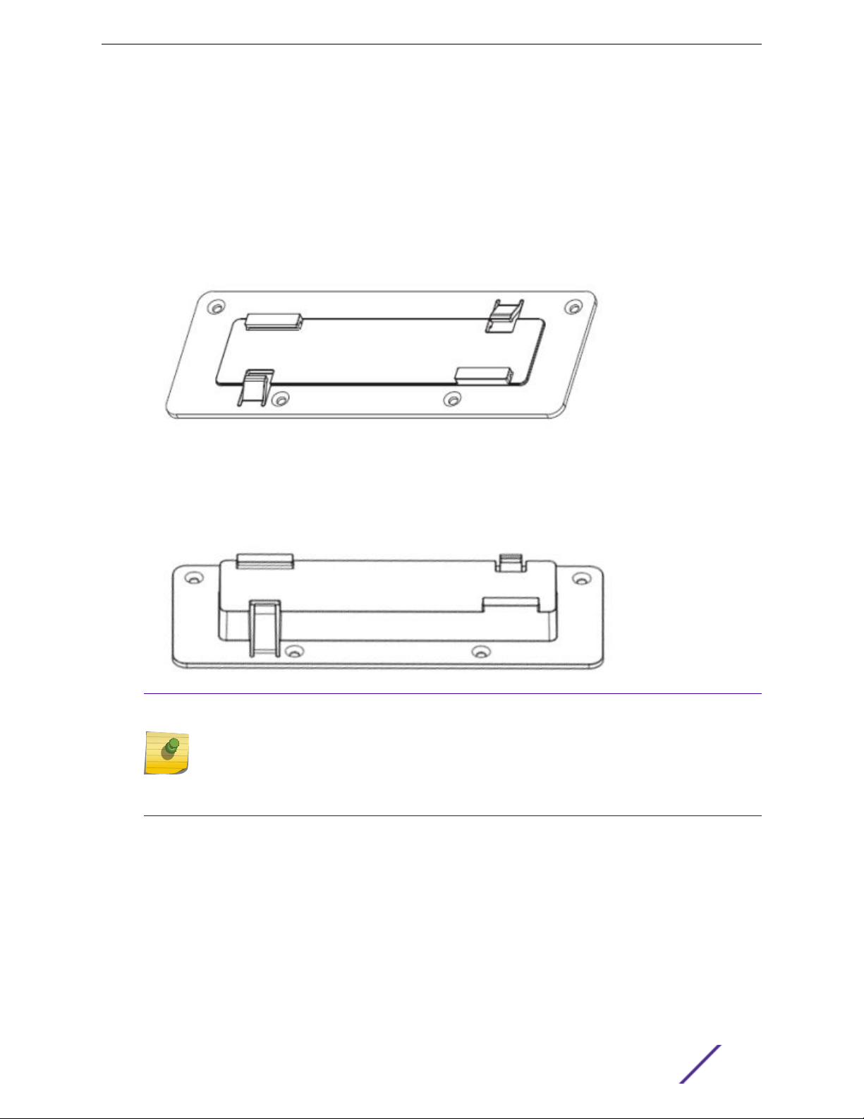
WS-MBI-DCU01 Mounting Bracket for Drop Ceiling
The optional WS-MBI-DCU01 mounting bracket fits 9/16", 14MM, 15/16", 24MM, 1.5", and 38MM wide drop
ceiling rails. This bracket uses four M3 flat head screws to attach it to the AP3825.
ExtremeWireless™ WS-AP3825i & WS-AP3825e Installation Guide for version . 20
Page 21

Installation
Figure 10: Mounting Bracket: WS-MBI-DCU01
To install the mounting bracket:
ExtremeWireless™ WS-AP3825i & WS-AP3825e Installation Guide for version . 21
Page 22

Installation
1 Attach the WS-MBI-DCU01 to the AP using the screws provided. If needed, pull the handle and slide
the top piece to access the additional screw holes that are underneath the handle. The four screw
holes are indicated by the green arrows in the following figure:
Figure 11: Sliding Handle and Screw Holes
2 Move the ceiling tile away from the T-bar.
3 Raise the locking bracket handle slightly and open the space between clips so that the space is
wider than the T-bar.
4 Put the stationary side of the bracket hooks on the T-bar.
5 Putting your hand over the T-bar, grab the two vertical parts of the WS-MBI-DCU01 and squeeze
them together until all four clips are holding onto the T-bar securely and the locking tab engages.
6 Gently rock the AP to verify that it is stable and will not fall o of the T-bar.
7 Cut holes in the ceiling tile as needed, and then thread the cables through the ceiling tile if
necessary. Attach the cables and start the AP.
8 Put the ceiling tiles back in place.
ExtremeWireless™ WS-AP3825i & WS-AP3825e Installation Guide for version . 22
Page 23

WS-MBI-WALL-01 Mounting Bracket on Junction/Gang Box
The WS-MBI-WALL-01 can be mounted on a junction/gang box, wall, or a solid ceiling. When mounting
on a solid ceiling, it is required that you use a Kensington lock or an equivalent lock.
Installation
Figure 12: WS-MBI-WALL-01 Bracket
To mount the WS-MBI-WALL-01 bracket on a junction or gang box:
1 Put the center of the bracket as close as possible to the center of the box. Find two bracket holes
that line up with the box screw holes. The bracket holes that you select should be on opposite sides
of the center hole.
2 Feed the LAN cable(s) from the box going through the semi-circular center hole of the bracket.
3 Using the provided screw hardware, attach the bracket to the box using the two holes you identified
previously. Tighten the screws to a torque of 9.0 inch-lbs.
4 Attach the LAN cable(s) to the AP and push the remaining cable length(s) back into the box.
5 Align the AP3825 mounting holes onto the two mounting circles and slide it down.
6 (Required for ceiling installations) Attach a Kensington lock (or its equivalent) through the lower left
tab and into the AP.
ExtremeWireless™ WS-AP3825i & WS-AP3825e Installation Guide for version . 23
Page 24

WS-MBI-WALL-01 Mounting Bracket on Wall or Solid Ceiling
The WS-MBI-WALL-01 can be mounted on a junction/gang box, wall, or a solid ceiling. When mounting
on a solid ceiling, it is required that you use a Kensington lock or an equivalent lock.
To mount the WS-MBI-WALL-01 bracket on a wall or solid ceiling:
1
Installation
Figure 13: Beveled Holes for Wall or Solid Ceiling Mounting (WS-MBI-WALL-01)
2 Mark the centers of the four beveled hole locations. Drill those locations and insert screw anchors if
the wall is made of drywall, plaster, or plaster-board.
3 Attach the bracket with four screws in the anchors. Tighten the screws to 9.0 inch-lbs.
4 Attach the LAN cable(s) to the AP and place the remaining cable length(s) back as desired.
5 Align the AP3825 mounting holes onto the two mounting circles and slide it down.
6 Attach a Kensington lock (or an equivalent lock) through the lower left tab and into the AP, if
desired, to prevent easy removal or minimize AP movement. This step is required for mounting on a
ceiling, and optional for wall mounting.
LAN/Console Connections
Note
Lan/Console connectors with shrouds will not fit into the ports. An optional jumper cable may
be used or the shroud removed.
ExtremeWireless™ WS-AP3825i & WS-AP3825e Installation Guide for version . 24
Page 25

The WS-AP3825 has both a LAN and a Console port. Refer to Figure 1-1 on page 1-2 for the location of
these ports.
During administration and maintenance through the LAN or Console, the AP must have a power
connection through either an Ethernet PoE cable or a DC power supply.
Power Connections
The AP can be powered in one of the following ways:
Power over Ethernet (PoE)
•
Power is provided through the RJ45 Ethernet port (LAN port) on the top of the AP. This is the
preferred method of powering the AP on ceiling and high wall installations.
Power by external power supply
•
Where a PoE-capable Ethernet connection is unavailable or impractical, an external 12V DC power
supply may be ordered separately to power the AP from a standard AC wall outlet.
Installation
Connecting an External DC Power Supply to the WS-AP3825
There are no wall mounts for the 12V DC power supplies. To connect a power supply to the AP for
everyday operation, mount the AP and plug the power supply in to the DC-IN port (callout 3 in Figure 1
on page 8 and Figure 2 on page 9). If you have taken the AP o its mount for configuration and
maintenance, you will still need to get power to it during the maintenance from a DC power supply or
PoE LAN connector.
Configuring AP Channel Settings
The WS-AP3825e must be installed by a professional installer. Before starting the installation, the
installer needs to determine/configure the following:
Determine the Antenna Model on page 25
•
Configuring Radio RF Port on page 26
•
Configuring Radio Channel on page 27
•
Configuring Radio Transmit (Tx) Power on page 29
•
Determine the Antenna Model
The professional installer needs to determine antenna models and the number of antenna ports for that
model. The number of ports can be determined from visual inspection of the antenna or from the
antenna model name as follows:
If the antenna model name contains a T or X (for example PRO-AO-xTxxxxx or AO-xXxxxxx), it is a
•
triple port antenna.
If the antenna model name contains a D (for example PRO-AO-xDxxxxx), it is a dual port antenna.
•
If the antenna model name contains an S (for example PRO-AO-xSxxxxx), it is a single port antenna.
•
ExtremeWireless™ WS-AP3825i & WS-AP3825e Installation Guide for version . 25
Page 26

Configuring Radio RF Port
The professional installer configures Radio RF ports where antenna ports will be connected.
Note
All professional antenna model names are prefixed with PRO.
To configure Radio RF Ports through the ExtremeWireless Assistant:
1 Log into the Wireless Assistant.
2 From the top menu, click AP.
The Wireless AP screen is displayed.
3 Click the APs button in the left pane, then in the Wireless AP list, select the Wireless AP whose
properties you want to modify.
The AP Properties tab displays Wireless AP information.
Installation
ExtremeWireless™ WS-AP3825i & WS-AP3825e Installation Guide for version . 26
Page 27

4 Click Professional Install.
The Professional Install Dialog displays.
5 Modify the Radio Antenna Type as follows:
If attaching triple port antennas, all three RF port should be configured with the same antenna
•
type.
If attaching dual port antennas, two of the radio RF ports should be configured with the same
•
antenna type and the third (non-active port) should be configured to None.
If attaching single port antennas, radio ports where antenna should be connected has to be set
•
to the antenna type and non-active port should be set to None.
6 Modify Radio Attenuation as follows:
Add any attenuation (dBm non-negative) due to cable loss or attenuator added to the line
•
between AP port and the antenna.
Same attenuator loss is assumed and is required for all three ports of the radio except when one
•
or more port is not connected to the antenna and is properly terminated as describe in next step.
Professional installer is responsible for accurately configuring port Attenuation. In no case, port
•
attenuation should be configured higher than actual attenuation between the AP port and the
antenna.
7 Install a terminator (rf 50 Ohm) on all ports where an antenna is not connected.
Installation
Configuring Radio Channel
1 Click the APs button in the left pane, then in the Wireless AP list, select the Wireless AP whose
properties you want to modify.
The AP Properties tab displays Wireless AP information.
2 Click the Radio 1 tab.
ExtremeWireless™ WS-AP3825i & WS-AP3825e Installation Guide for version . 27
Page 28

3 Configure the desired Radio Mode, and Channel Width.
Installation
4 From the Request a New Channel drop-down menu, select a channel according to the site channel
plan.
5 Request the AP to auto select the channel from the channel list set in the Channel Plan setting.
6 Repeat the process for Radio 2.
ExtremeWireless™ WS-AP3825i & WS-AP3825e Installation Guide for version . 28
Page 29

Configuring Radio Transmit (Tx) Power
Based on the configured mode, channel, channel plan, and channel width for the specific antenna, the
professional installer must enter the corresponding Transmit Power (Tx Power) for the desired Radio
using the ExtremeWireless Assistant.
1 Log into the Wireless Assistant.
2 From the top menu, click AP.
The Wireless AP screen displays.
3 Click the AP button in the left pane, then in the Wireless AP list, select the Wireless AP whose
properties you want to modify.
The AP Properties tab displays Wireless AP information.
4 Click the Radio 1 tab.
Max Tx Power is automatically determined based on regulatory domain/country, antenna selected,
line attenuation configured, channel, and certification testing.
Installation
5 Professional installer is responsible for accurately configuring port Attenuation. In no case, port
attenuation should be configured higher than actual attenuation between the AP port and the
antenna.
6 Repeat the process for Radio 2.
ExtremeWireless™ WS-AP3825i & WS-AP3825e Installation Guide for version . 29
Page 30

A Specifications
External Power Supplies
Internal Antenna Access Points
External Antennas
This appendix lists the specifications for the WS-AP3825i and WS-AP3825e access points and an
external 12V DC power supply.
Table 5: Specifications for the WS-AP3825i and WS-AP3825e
Item Specification
Enclosure material Metal base, plastic housing
Power source 802.3af compliant PoE PD,
12V DC input
Power consumption < 12.94W (Max.)
Outside dimensions (max) WS-AP3825e Length: 190.5mm (7.5")
Width: 145mm to 180.0mm (7.5" to 7.09")
Thickness (not including mounting bracket): 29mm
(1.13") to 38mm (1.5").
Antenna (WS-AP3825i only) 6x internal antennas, single band
Uplink Interface GbE Ethernet x1 with PoE
RoHS compliant Yes
Radio Configuration IEEE 802.11ac, a/b/g/n
2.4/5 GHz single-band,
Dual-radio, 3x3:3 MIMO
Operating temperature 32°F to 122°F (0°C to +50°C)
External Power Supplies
WS-AP3825 APs may be powered by IEEE 802.3af compliant PoE cables connected to the Ethernet
ports in the connector bay. This is usually the preferred method of powering for users that plan to
mount the devices on ceilings or high up on walls. You can also power these APs with optional external
power supplies.
Table 6: Universal Specifications for an External Power Supply
Item Specification
Enclosure material Plastic housing
AC Input 100-240V
DC output 12V
ExtremeWireless™ WS-AP3825i & WS-AP3825e Installation Guide for version . 30
Page 31

Table 6: Universal Specifications for an External Power Supply (continued)
Item Specification
Output current (max) 2A
Output power (max) 24W
Table 7 lists recommended power supplies for the WS-AP3825, by country:
Table 7: Recommended DC Power Supplies for WS-AP3825
Country Extreme Networks Part Number
Australia WS-PS3X12-AU
Brazil WS-PS3X12-BR
China WS-PS3X12-CN
EU WS-PS3X12-EU
UK WS-PS3X12-UK
Specifications
US WS-PS3X12-NAM
Internal Antenna Access Points
The WS-AP3825i is an indoor access with six integrated internal antennas. The following specifications
are for the internal antennas:
Table 8: WS-AP3825i Internal Antennas
Model Type Application Description Gain (dBi) Frequency (GHz) Connector
WS-AP3825i Indoor MIMO, Single-
band
The following radiation patterns apply to the antennas in the WS-AP3825i only. In these diagrams, 0
degree is AP's front and +/- 180 degree is AP's back.
5 dBi 2.4 None
6 dB 5 None
ExtremeWireless™ WS-AP3825i & WS-AP3825e Installation Guide for version . 31
Page 32

Specifications
Figure 14: Horizontal Radiation Pattern 2.4 GHz
ExtremeWireless™ WS-AP3825i & WS-AP3825e Installation Guide for version . 32
Page 33

Specifications
Figure 15: Vertical XZ Radiation Pattern 2.4 GHz
ExtremeWireless™ WS-AP3825i & WS-AP3825e Installation Guide for version . 33
Page 34

Specifications
Figure 16: Vertical YZ Radiation Pattern 2.4 GHz
ExtremeWireless™ WS-AP3825i & WS-AP3825e Installation Guide for version . 34
Page 35

Specifications
Figure 17: Horizontal Radiation Pattern 5 GHz
ExtremeWireless™ WS-AP3825i & WS-AP3825e Installation Guide for version . 35
Page 36

Specifications
Figure 18: Vertical XZ Radiation Pattern 5 GHz
ExtremeWireless™ WS-AP3825i & WS-AP3825e Installation Guide for version . 36
Page 37

Specifications
Figure 19: Vertical YZ Radiation Pattern 5 GHz
External Antennas
Table 9 lists the certified external antennas for WS-AP3825e. For more detailed specifications and
radiation pattern diagrams, see the ExtremeWireless External Antenna Site Preparation and Installation
Guide.
Table 9: Certified External Antennas for WS-AP3825e
Model Application Description Gain (dBi) Frequency (GHz) Connector Type
WS-ANT-2DIP-3 Indoor MIMO; Single-
band
WS-ANT-5DIP-3 Indoor MIMO; Single-
band
WS-AI-DX02360 Indoor MIMO; Dual-band 2 dBi 2.4-2.5,
WS-AI-DT05120 Indoor MIMO; Sector;
Dual-band
3 dBi 2.4 3xRSMA
3 dBi 5.0 3xRSMA
5.15-5.85
5 dBi x 3,
2:1
2.3 – 2.7,
4.9 – 6.1
RSMA
RSMA
ExtremeWireless™ WS-AP3825i & WS-AP3825e Installation Guide for version . 37
Page 38

Specifications
Table 9: Certified External Antennas for WS-AP3825e (continued)
Model Application Description Gain (dBi) Frequency (GHz) Connector Type
WS-AI-DX10055 Indoor MIMO; Sector,
Dualband
WS-AI-DX07025 Indoor MIMO; Sector;
Dual-band
10 dBi
6 dBi
6.5 dBi
5.5 dBi
2.4 – 2.5,
5.1 – 5.9
2.4 – 2.5,
5.1 – 5.9
RSMA
RSMA
ExtremeWireless™ WS-AP3825i & WS-AP3825e Installation Guide for version . 38
Page 39

B Regulatory Information
ExtremeWireless WS-AP3825i and WS-AP3825e
Warning
Warnings identify essential information. Ignoring a warning can lead to problems with the
application.
This appendix provides regulatory information for the Extreme Networks Wireless WS-AP3825i and
WS-AP3825e access points.
Note
Throughout this appendix, the term ExtremeWireless AP3825 refers to the AP models WSAP3825i, and WS-AP3825e. Specific AP models are identified in this appendix only where it is
necessary to do so.
Warning
Changes or modifications made to the ExtremeWireless AP3825 which are not expressly
approved by Extreme Networks could void the user's authority to operate the equipment.
Only authorized Extreme Networks service personnel are permitted to service the system.
Procedures that should be performed only by Extreme Networks personnel are clearly
identified in this guide.
ExtremeWireless WS-AP3825i and WS-AP3825e
The following regulatory information applies to the ExtremeWireless access points WS-AP3825i and
WS-AP3825e.
United States
FCC Declaration of Conformity Statement
This device complies with Part 15 of the FCC Rules. Operation is subject to the following two conditions:
This device may not cause harmful interference.
•
This device must accept any interference received, including interference that may cause undesired
•
operation.
This equipment has been tested and found to comply with the limits for a Class B digital device,
pursuant to Part 15 of the FCC Rules. These limits are designed to provide reasonable protection against
harmful interference when the equipment is operated in a residential and business environment. This
equipment generates, uses, and radiates radio frequency energy, and if not installed and used in
accordance with instructions, may cause harmful interference. However, there is no guarantee that
interference will not occur. If this equipment does cause harmful interference, which can be determined
ExtremeWireless™ WS-AP3825i & WS-AP3825e Installation Guide for version . 39
Page 40

Regulatory Information
by turning the equipment o and on, the user is encouraged to try to correct the interference by one or
more of the following measures:
Reorient or relocate the transmitting antenna.
•
Increase the separation between the equipment or devices.
•
Connect the equipment to an outlet other than the receiver's.
•
Consult a dealer or an experienced radio/TV technician for suggestions.
•
USA Conformance Standards
This equipment meets the following conformance standards:
Safety
UL 60950-1
•
EMC
FCC CFR 47 Part 15, Class B
•
Radio transceiver
CFR 47 Part 15.247, Subpart C
•
CFR 47 Part 15.407, Subpart E
•
Other
IEEE 802.11a (5 GHz)
•
IEEE 802.11b/g (2.4 GHz)
•
IEEE 802.11n
•
IEEE 802.3at (PoE)
•
IEEE 802.3af (PoE)
•
Warning
The ExtremeWireless AP3825 must be installed and used in strict accordance with the
manufacturer's instructions as described in this guide and related documentation for the
device to which the ExtremeWireless AP3825 is connected. Any other installation or use of
the product violates FCC Part 15 regulations.
This Part 15 radio device operates on a non-interference basis with other devices operating at
the same frequency when using the antennas provided or other Extreme Networks-certified
antennas. Any changes or modifications to the product not expressly approved by Extreme
Networks could void the user's authority to operate this device.
For the product available in the USA market, only channels 1 to 11 can be operated. Selection
of other channels in the 2.4 GHz band is not possible.
FCC RF Radiation Exposure Statement
The ExtremeWireless AP3825 complies with FCC RF radiated exposure limits set forth for an
uncontrolled environment. End users must follow the specific operating instructions for satisfying RF
exposure compliance. This device has been tested and has demonstrated compliance when
simultaneously operated in the 2.4 GHz and 5 GHz frequency ranges. This device must not be colocated or operated in conjunction with any other antenna or transmitter.
ExtremeWireless™ WS-AP3825i & WS-AP3825e Installation Guide for version . 40
Page 41

Regulatory Information
The radiated output power of the ExtremeWireless AP3825 is below the FCC radio frequency exposure
limits as specified in “Guidelines for Human Exposure to Radio Frequency Electromagnetic Fields” (OET
Bulletin 65, Supplement C). This equipment should be installed and operated with a minimum distance
of 20 cm between the radiator and your body or other colocated operating antennas.
Canada
Industry Canada Compliance Statement
This digital apparatus does not exceed the Class B limits for radio noise emissions from digital apparatus
as set out in the interference-causing equipment standard entitled “Digital Apparatus,” ICES-003 of
Industry Canada.
Cet appareil numerique respecte les limites de bruits radioelectriques applicables aux appareils
numeriques de Classe B prescrites dans la norme sur le materiel brouilleur: “Appareils Numeriques,”
NMB-003 edictee par le Industrie Canada.
This device complies with RSS-210 of the Industry Canada Rules. Operation is subject to the following
conditions:
This device may not cause harmful interference.
•
This device must accept any interference received, including interference that may cause undesired
•
operation.
This Class B digital apparatus complies with Canadian ICES-003.
•
Operation in the 5150-5250 MHz band is only for indoor usage to reduce potential for harmful
•
interference to co-channel mobile satellite systems.
Users are advised that high power radars are allocated as primary users (meaning they have priority)
•
and can cause interference in the 5250-5350 MHz and 5470-5850 MHz bands of LELAN devices.
For the product available in the Canadian market, only channels 1 to 11 can be operated. Selection of
•
other channels in the 2.4 GHz band is not possible.
Under Industry Canada regulations, this radio transmitter may only operate using an antenna of a
•
type and maximum (or lesser) gain approved for the transmitter by Industry Canada. To reduce
potential radio interference to other users, the antenna type and its gain should be so chosen that
the equivalent isotropically radiated power (e.i.r.p.) is not more than that necessary for successful
communication.
Ce dispositif est conforme à la norme CNR-210 d'Industrie Canada applicable aux appareils radio
exempts de licence. Son fonctionnement est sujet aux conditions suivantes:
Le dispositif ne doit pas produire de brouillage préjudiciable.
•
Ce dispositif doit accepter tout brouillage reçu, y compris un brouillage susceptible de provoquer un
•
fonctionnement indésirable.
Ce dispositif est conforme à la norme NMB-003 edictee par le Industrie Canada.
•
Les dispositifs fonctionnant dans la bande 5 150-5 250 MHz sont réservés uniquement pour
•
uneutilisation à l’intérieur afin de réduire les risques de brouillage préjudiciable aux systèmes de
satellites mobiles utilisant les mêmes canaux.
Les utilisateurs devraient aussi être avisés que les utilisateurs de radars de haute puissance sont
•
désignés utilisateurs principaux (c.-à-d., qu'ils ont la priorité) pour les bandes 5250-5350 MHz et
ExtremeWireless™ WS-AP3825i & WS-AP3825e Installation Guide for version . 41
Page 42

5470-5850 MHz et que ces radars pourraient causer du brouillage et/ou des dommages aux
dispositifs LAN-EL.
Pour le produit disponible sur le marché canadien, seuls les canaux 1 à 11 peuvent être utilisés. Il est
•
impossible de sélectionner d’autres canaux dans la bande de 2.4 GHz.
Conformément à la réglementation d'Industrie Canada, le présent émetteur radio peut fonctionner
•
avec une antenne d'un type et d'un gain maximal (ou inférieur) approuvé pour l'émetteur par
Industrie Canada. Dans le but de réduire les risques de brouillage radioélectrique à l'intention des
autres utilisateurs, il faut choisir le type d'antenne et son gain B-4 ExtremeWireless WS-AP3825i and
WS-AP3825e de sorte que la puissance isotrope rayonnée équivalente (p.i.r.e.) ne dépasse pas
l'intensité nécessaire à l'établissement d'une communication satisfaisante.
Canada Conformance Standards
This equipment meets the following conformance standards:
Safety
C22.2 No.60950-1-03
•
EMC
ICES-003, Class B
•
Regulatory Information
Radio transceiver
RSS-210 (2.4 GHz and 5 GHz)
•
Other
IEEE 802.11a (5 GHz)
•
IEEE 802.11b/g (2.4 GHz)
•
IEEE 802.11n
•
IEEE 802.3at (PoE)
•
IEEE 802.3af (PoE)
•
RF Safety Distance
The antennas used for this transmitter must be installed to provide a separation distance of at least 20
cm from all persons and must not be co-located or operating in conjunction with another antenna or
transmitter.
Les antennes de ce transmetteur doivent être installées à une distance d’au moins 20 cm de toute
personne et ne doivent pas être en placées à proximité immédiate ou utilisées conjointement avec une
autre antenne ou un autre transmetteur.
European Community
The ExtremeWireless AP3825 is designed for use in the European Union and other countries with
similar regulatory restrictions where the end user or installer is allowed to configure the
ExtremeWireless AP3825 for operation by entry of a country code relative to a specific country. After
the country code is selected, the ExtremeWireless AP3825 uses the proper frequencies and power
outputs for that country code.
ExtremeWireless™ WS-AP3825i & WS-AP3825e Installation Guide for version . 42
Page 43

Regulatory Information
The ExtremeWireless AP3825 is intended for indoor use and must be installed in a proper indoor
location. Contact local Authority for procedure to follow and regulatory information. For more details on
legal combinations of frequencies, power levels and antennas, contact Extreme Networks.
Declaration of Conformity with R&TTE Directive of the European Union 1999/5/EC
The following symbol indicates compliance with the Essential Requirements of the R&TTE Directive of
the European Union (1999/5/EC).
Declaration of Conformity in Languages of the European Community
English Hereby, Extreme Networks, declares that this Radio LAN
device is in compliance with the essential requirements
and other relevant provisions of Directive 1999/5/EC.
Finnish Valmistaja Extreme Networks vakuuttaa täten että
Radio LAN device tyyppinen laite on direktiivin
1999/5/EY oleellisten vaatimusten ja sitä koskevien
direktiivin muiden ehtojen mukainen.
Dutch Hierbij verklaart Extreme Networks dat het toestel
Radio LAN device in overeenstemming is met de
essentiële eisen en de andere relevante bepalingen van
richtlijn 1999/5/EG.
Bij deze verklaart Extreme Networks dat deze
Radio LAN device voldoet aan de essentiële eisen
en aan de overige relevante bepalingen van
Richtlijn 1999/5/EC.
French Par la présente Extreme Networks déclare que l'appareil
Radio LAN device est conforme aux exigences
essentielles et aux autres dispositions pertinentes de la
directive 1999/5/CE.
Par la présente, Extreme Networks déclare que ce
Radio LAN device est conforme aux exigences
essentielles et aux autres dispositions de la
directive 1999/5/CE qui lui sont applicables.
Swedish Härmed intygar Extreme Networks att denna Radio
LAN device står I överensstämmelse med de väsentliga
egenskapskrav och övriga relevanta bestämmelser som
framgår av direktiv 1999/5/EG.
Danish Undertegnede Extreme Networks erklærer herved, at
følgende udstyr Radio LAN device overholder de
væsentlige krav og øvrige relevante krav i direktiv
1999/5/EF.
German Hiermit erklärt Extreme Networks die Übereinstimmung
des "WLAN Wireless Controller bzw. Access Points" mit
den grundlegenden Anforderungen und den anderen
relevanten Festlegungen der Richtlinie 1999/5/EG.
Greek
ExtremeWireless™ WS-AP3825i & WS-AP3825e Installation Guide for version . 43
ΜΕ ΤΗΝ ΠΑΡΟΥΣΑ Extreme Networks ΔΗΛΩΝΕΙ
ΟΤΙ Radio LAN device ΣΥΜΜΟΡΦΩΝΕΤΑΙ ΠΡΟΣ
Page 44

Regulatory Information
ΤΙΣ ΟΥΣΙΩΔΕΙΣ ΑΠΑΙΤΗΣΕΙΣ ΚΑΙ ΤΙΣ ΛΟΙΠΕΣ
ΣΧΕΤΙΚΕΣ ΔΙΑΤΑΞΕΙΣ ΤΗΣ ΟΔΗΓΙΑΣ 1999/5/ΕΚ.
Icelandic Extreme Networks lysir her med yfir að thessi bunadur,
Radio LAN device, uppfyllir allar grunnkrofur, sem
gerdar eru i R&TTE tilskipun ESB nr 1999/5/EC.
Italian
Spanish Por medio de la presente Extreme Networks declara
Portuguese Extreme Networks declara que este Radio LAN device
Malti Hawnhekk, Extreme Networks, jiddikjara li dan Radio
New Member States Requirements of Declaration of Conformity
Estonian
Hungary Alulírott, Extreme Networks nyilatkozom, hogy a Radio
Con la presente Extreme Networks dichiara che questo
Radio LAN device è conforme ai requisiti essenziali ed
alle altre disposizioni pertinenti stabilite dalla direttiva
1999/5/CE.
que el Radio LAN device cumple con los requisitos
esenciales y cualesquiera otras disposiciones aplicables
o exigibles de la Directiva 1999/5/CE
está conforme com os requisitos essenciais e outras
disposições da Directiva 1999/5/CE.
LAN device jikkonforma mal-htigijiet essenzjali u ma
provvedimenti ohrajn relevanti li hemm fid-Dirrettiva
1999/5/EC.
Käesolevaga kinnitab Extreme Networks seadme Radio
LAN device vastavust direktiivi 1999/5/EÜ põhinõuetele
ja nimetatud direktiivist tulenevatele teistele
asjakohastele sätetele.
LAN device megfelel a vonatkozó alapvetõ
követelményeknek és az 1999/5/EC irányelv egyéb
elõírásainak.
Slovak Extreme Networks týmto vyhlasuje, že Radio LAN
device spĺňa základné požiadavky a všetky príslušné
ustanovenia Smernice 1999/5/ES.
Czech Extreme Networks tímto prohlašuje, že tento Radio LAN
device je ve shodě se základními požadavky a dalšími
příslušnými ustanoveními směrnice 1999/5/ES."
Slovenian Šiuo Extreme Networks deklaruoja, kad šis Radio LAN
device atitinka esminius reikalavimus ir kitas 1999/5/EB
Direktyvos nuostatas.
Latvian Ar šo Extreme Networks deklarē, ka Radio LAN device
atbilst Direktīvas 1999/5/EK būtiskajām prasībām un
citiem ar to saistītajiem noteikumiem
Lithuanian Extreme Networks deklaruoja, kad Radio LAN device
atitinka 1999/5/EC Direktyvos esminius reikalavimus ir
kitas nuostatas"
Polish Niniejszym, Extreme Networks, deklaruję, że Radio LAN
device spełnia wymagania zasadnicze oraz stosowne
postanowienia zawarte Dyrektywie 1999/5/EC.
ExtremeWireless™ WS-AP3825i & WS-AP3825e Installation Guide for version . 44
Page 45

European Conformance Standards
This equipment meets the following conformance standards:
Safety
2006/95/EC Low Voltage Directive (LVD)
•
IEC/EN 60950-1 + National Deviations
•
EMC (Emissions / Immunity)
2004/108/EC EMC Directive
•
EN 55011/CISPR 11, Class B, Group 1 ISM
•
EN 55022/CISPR 22, Class B
•
EN 55024/CISPR 24, includes IEC/EN 61000-4-2,3,4,5,6,11
•
EN 61000-3-2 and -3-3 (Harmonics and Flicker)
•
EN 60601-1-2 (EMC immunity for medical equipment)
•
EN 50385 (EMF)
•
ETSI/EN 301 489-1 & -17
•
Regulatory Information
Radio transceiver
R&TTE Directive 1999/5/EC
•
ETSI/EN 300 328 (2.4 GHz)
•
ETSI/EN 301 893 (5 GHz)
•
Other
IEEE 802.11a (5 GHz)
•
IEEE 802.11b/g (2.4 GHz)
•
IEEE 802.11n
•
IEEE 802.3at (PoE)
•
IEEE 802.3af (PoE)
•
RoHS
European Directive 2002/95/EC
•
Conditions of use in the European Community
Some EU countries allow outdoor operation with limitations and restrictions, which are described in this
section. It is the responsibility of the end user to ensure operation in accordance with these rules,
frequencies, and transmitter power output. The ExtremeWireless AP3825 must not be operated until
configured for the customer’s geographic location.
Caution
The user or installer is responsible to ensure that the ExtremeWireless AP3825 is operated
according to channel limitations, indoor / outdoor restrictions, license requirements, and
within power level limits for the current country of operation. A configuration utility has been
provided with the Wireless AP to allow the end user to check the configuration and make
necessary configuration changes to ensure proper operation in accordance with the spectrum
usage rules for compliance with the European R&TTE directive 1999/5/EC.
ExtremeWireless™ WS-AP3825i & WS-AP3825e Installation Guide for version . 45
Page 46

Regulatory Information
Caution
Please follow the instructions in this user guide to configure the ExtremeWireless AP3825.
Each Wireless AP is configured with a default group of settings. There is the ability to
•
change these settings. The user or installer is responsible to ensure that each
ExtremeWireless AP3825 is configured properly.
The software within the Wireless AP automatically limits the allowable channels and
•
output power determined by the selected country code. Selecting the incorrect country of
operation or misidentifying the antenna being used,may result in illegal operation and may
cause harmful interference to other systems.
This device employs a radar detection feature required for European Community operation
•
in the 5 GHz band. This feature is automatically enabled when the country of operation is
correctly configured for any European Community country. The presence of nearby radar
operation may result in temporary interruption of operation of this device. The radar
detection feature will automatically restart operation on a channel free of radar.
The 5150- 5350 MHz band, channels 36, 40, 44, 48, 52, 56, 60, or 64, are restricted to
•
indoor use only.
The 2.4 GHz band, channels 1 - 13, may be used for indoor use but there may be some
•
channel restrictions.
European Spectrum Usage Rules
The AP configured with approved internal antennas can be used for indoor transmissions throughout
the European community as displayed in the following table. Some restrictions apply in France, Greece,
and Italy.
Table 10: European Spectrum Usage Rules
Country 5.15-5.25 (GHz)
Channels:
36,40,44,48
Austria Indoor only Indoor only Indoor or outdoor Indoor or outdoor
Belgium Indoor only Indoor only Indoor or outdoor*Indoor or outdoor
Bulgaria Indoor only Indoor only Indoor or outdoor Indoor or outdoor
Croatia Indoor only Indoor only Indoor or outdoor Indoor or outdoor
Cyprus Indoor only Indoor only Indoor or outdoor Indoor or outdoor
Czech Rep. Indoor only Indoor only Indoor or outdoor Indoor or outdoor
Denmark Indoor only Indoor only Indoor or outdoor Indoor or outdoor
Estonia Indoor only Indoor only Indoor or outdoor Indoor or outdoor
Finland Indoor only Indoor only Indoor or outdoor Indoor or outdoor
5.25-5.35 (GHz)
Channels:
52,56,60,64
5.47-5.725 (GHz)
Channels:
100,104,108,112,116,
132,136,140
2.4-2.4835 (GHz)
Channels: 1 to 13
(Except Where
Noted)
France Indoor only Indoor only Indoor or outdoor Indoor or outdoor
Germany Indoor only Indoor only Indoor or outdoor Indoor or outdoor
Greece Indoor only Indoor only Indoor (Outdoor w/
License)
ExtremeWireless™ WS-AP3825i & WS-AP3825e Installation Guide for version . 46
Indoor (Outdoor w/
license)
Page 47

Regulatory Information
Table 10: European Spectrum Usage Rules (continued)
Country 5.15-5.25 (GHz)
Channels:
36,40,44,48
Hungary Indoor only Indoor only Indoor or outdoor Indoor or outdoor
Iceland Indoor only Indoor only Indoor or outdoor
Ireland Indoor only Indoor only Indoor or outdoor Indoor or outdoor
Italy Indoor only Indoor only Indoor or outdoor Indoor (Outdoor w/
Latvia Indoor only Indoor only Indoor or outdoor Indoor or outdoor
Liechtenstein Indoor only Indoor only Indoor or outdoor Indoor or outdoor
Lithuania Indoor only Indoor only Indoor or outdoor Indoor or outdoor
Luxembourg Indoor only Indoor only Indoor or outdoor Indoor or outdoor
Malta Indoor only Indoor only Indoor or outdoor Indoor or outdoor
5.25-5.35 (GHz)
Channels:
52,56,60,64
5.47-5.725 (GHz)
Channels:
100,104,108,112,116,
132,136,140
2.4-2.4835 (GHz)
Channels: 1 to 13
(Except Where
Noted)
license)
Netherlands Indoor only Indoor only Indoor or outdoor Indoor or outdoor
Norway Indoor only Indoor only Indoor or outdoor Indoor or outdoor
Poland Indoor only Indoor only Indoor or outdoor Indoor or outdoor
Portugal Indoor only Indoor only Indoor or outdoor Indoor or outdoor
Romania Indoor only Indoor only Indoor or outdoor Indoor or outdoor
Slovak Rep. Indoor only Indoor only Indoor or outdoor Indoor or outdoor
Slovenia Indoor only Indoor only Indoor or outdoor Indoor or outdoor
Spain Indoor only Indoor only Indoor or outdoor Indoor or outdoor
Sweden Indoor only Indoor only Indoor or outdoor Indoor or outdoor
Switzerland Indoor only Indoor only Indoor or outdoor Indoor or outdoor
Turkey Indoor only Indoor only Indoor or outdoor Indoor or outdoor
U.K Indoor only Indoor only Indoor or outdoor Indoor or outdoor
Certifications of Other Countries
The ExtremeWireless AP3825 has been certified for use in various other countries. Once the correct
country code is selected, the Wireless AP automatically uses the proper frequencies and power outputs
for that country code.
It is the responsibility of the end user to select the proper country code for the country within which the
device will be operated, or run the risk violating local laws and regulations.
Other Country Specific Compliance Standards, Approvals and Declarations
IEC 60950-1 CB Scheme + National Deviations
•
AS/NZS 60950.1 (Safety)
•
ExtremeWireless™ WS-AP3825i & WS-AP3825e Installation Guide for version . 47
Page 48

Regulatory Information
AS/NZS 3548 (Emissions via EU standards – ACMA)
•
AS/NZS 4288 (Radio via EU standards)
•
EN 300 328 (2.4 GHz)
•
EN 301 893 (5 GHz)
•
EN 301 489-1 & -17 (RLAN)
•
IEEE 802.11a (5 GHz)
•
IEEE 802.11b/g (2.4 GHz)
•
IEEE 802.11n
•
IEEE 802.3at (PoE)
•
IEEE 802.3af (PoE)
•
RF Safety Distance
The antennas used for this transmitter must be installed to provide a separation distance of at least 20
cm from all persons and must not be co-located or operating in conjunction with another antenna or
transmitter.
ExtremeWireless™ WS-AP3825i & WS-AP3825e Installation Guide for version . 48
 Loading...