

Page 1

ExtremeWireless
External
Antenna with Wave 2
Site Preparation and Installation Guide
™
9034959
Published May 2016
Page 2

Copyright © 2016 Extreme Networks All rights reserved.
Legal Notice
Extreme Networks, Inc. reserves the right to make changes in specifications and other information
contained in this document and its website without prior notice. The reader should in all cases
consult representatives of Extreme Networks to determine whether any such changes have been
made.
The hardware, firmware, software or any specifications described or referred to in this document
are subject to change without notice.
Trademarks
Extreme Networks and the Extreme Networks logo are trademarks or registered trademarks of
Extreme Networks, Inc. in the United States and/or other countries.
All other names (including any product names) mentioned in this document are the property of
their respective owners and may be trademarks or registered trademarks of their respective
companies/owners.
For additional information on Extreme Networks trademarks, please see:
www.extremenetworks.com/company/legal/trademarks
Support
For product support, including documentation, visit: http://www.extremenetworks.com/support/
For information, contact:
Extreme Networks, Inc.
6480 Via Del Oro
San Jose, California 95119
USA
Page 3

Table of Contents
About This Guide....................................................................................................................... 4
Intended Audience...............................................................................................................................................................4
Text Conventions...................................................................................................................................................................4
Providing Feedback to Us.................................................................................................................................................5
Getting Help.............................................................................................................................................................................5
Related Publications............................................................................................................................................................6
Chapter 1: AP Site Preparation.................................................................................................7
ExtremeWireless Access Points that Support External Antennas................................................................7
Choosing Antennas for Wireless Network Configurations...............................................................................7
Determining the Antenna Locations........................................................................................................................... 8
Antenna Models....................................................................................................................................................................12
Cable Options........................................................................................................................................................................15
Contacting an Antenna Installation Company...................................................................................................... 15
Chapter 2: ExtremeWireless APs That Support External Antennas..................................17
Determining the Location of the AP.......................................................................................................................... 17
ExtremeWireless AP3965e............................................................................................................................................. 17
ExtremeWireless AP3935e............................................................................................................................................. 18
ExtremeWireless AP3865e............................................................................................................................................. 19
ExtremeWireless AP3825e............................................................................................................................................ 20
ExtremeWireless AP3805e............................................................................................................................................. 21
Chapter 3: Antenna Installation.............................................................................................23
Outdoor Antenna Kits......................................................................................................................................................23
Installation Overview.........................................................................................................................................................23
Grounding System............................................................................................................................................................. 24
Mounting the Antenna.....................................................................................................................................................24
Cable Installation Guidelines.........................................................................................................................................39
Routine Maintenance........................................................................................................................................................40
Chapter 4: Antenna Specifications........................................................................................ 41
External Antennas for Use with Outdoor APs...................................................................................................... 41
External Antennas for Use with Indoor APs......................................................................................................... 93
Chapter 5: Accessory Specifications...................................................................................140
Low-Loss Antenna Cables........................................................................................................................................... 140
Terminator: WS-CAB-RPSMATERM.........................................................................................................................144
Terminator: WS-CAB-NTERM.....................................................................................................................................144
Attenuators..........................................................................................................................................................................145
Extension Bracket: 30515 (WS-MB-WALLEXT01) ........................................................................................... 147
ExtremeWireless™ External Antenna with Wave 2 3
Page 4
About This Guide
This guide describes the requirements for the successful installation of the ExtremeWireless external
antennas used in a wireless network. An ExtremeWireless network consists of access points, controllers,
antennas, and associated accessories.
Warning
Only qualified personnel should perform installation procedures.
Intended Audience
The ExtremeWireless external antennas must be installed by an antenna installation professional who
can determine, provide, and install the necessary support structure and grounding system. The antenna
installation professional should be licensed or certified in accordance with local regulations.
This preface provides an overview of this guide and a brief summary of each chapter; defines the
conventions used in this document; and instructs how to obtain technical support from Extreme
Networks.
Text Conventions
The following tables list text conventions that are used throughout this guide.
Table 1: Notice Icons
Icon Notice Type Alerts you to...
General Notice Helpful tips and notices for using the product.
Note Important features or instructions.
Caution Risk of personal injury, system damage, or loss of data.
Warning Risk of severe personal injury.
New This command or section is new for this release.
ExtremeWireless™ External Antenna with Wave 2 4
Page 5

Table 2: Text Conventions
Convention Description
Screen displays
This typeface indicates command syntax, or represents information as it appears on the
screen.
About This Guide
The words enter and
type
[Key] names Key names are written with brackets, such as [Return] or [Esc]. If you must press two
Words in italicized type Italics emphasize a point or denote new terms at the place where they are defined in
When you see the word “enter” in this guide, you must type something, and then press
the Return or Enter key. Do not press the Return or Enter key when an instruction
simply says “type.”
or more keys simultaneously, the key names are linked with a plus sign (+). Example:
Press [Ctrl]+[Alt]+[Del]
the text. Italics are also used when referring to publication titles.
Providing Feedback to Us
We are always striving to improve our documentation and help you work better, so we want to hear
from you! We welcome all feedback but especially want to know about:
Content errors or confusing or conflicting information.
•
Ideas for improvements to our documentation so you can find the information you need faster.
•
Broken links or usability issues.
•
If you would like to provide feedback to the Extreme Networks Information Development team about
this document, please contact us using our short online feedback form. You can also email us directly at
internalinfodev@extremenetworks.com.
Getting Help
If you require assistance, contact Extreme Networks using one of the following methods:
Global Technical Assistance Center (GTAC) for Immediate Support
•
Phone: 1-800-998-2408 (toll-free in U.S. and Canada) or +1 408-579-2826. For the support
•
phone number in your country, visit: www.extremenetworks.com/support/contact
Email: support@extremenetworks.com. To expedite your message, enter the product name or
•
model number in the subject line.
GTAC Knowledge — Get on-demand and tested resolutions from the GTAC Knowledgebase, or
•
create a help case if you need more guidance.
The Hub — A forum for Extreme customers to connect with one another, get questions answered,
•
share ideas and feedback, and get problems solved. This community is monitored by Extreme
Networks employees, but is not intended to replace specific guidance from GTAC.
Support Portal — Manage cases, downloads, service contracts, product licensing, and training and
•
certifications.
Before contacting Extreme Networks for technical support, have the following information ready:
Your Extreme Networks service contract number and/or serial numbers for all involved Extreme
•
Networks products
A description of the failure
•
ExtremeWireless™ External Antenna with Wave 2 5
Page 6

A description of any action(s) already taken to resolve the problem
•
A description of your network environment (such as layout, cable type, other relevant environmental
•
information)
Network load at the time of trouble (if known)
•
The device history (for example, if you have returned the device before, or if this is a recurring
•
problem)
Any related Return Material Authorization (RMA) numbers
•
Related Publications
ExtremeWireless and ExtremeWireless AP documentation can be found on Extreme Documentation
page at: http://documentation.extremenetworks.com
Extreme recommends the following guides for users of ExtremeWireless products:
ExtremeWireless AP3912i Installation Guide
•
ExtremeWireless AP3965i & AP3965e Installation Guide
•
ExtremeWireless AP3935i & AP3935e Installation Guide
•
ExtremeWireless AP3825i & AP3825e Installation Guide
•
ExtremeWireless AP3805i FCC/ROW Installation Guide
•
ExtremeWireless AP3801i Quick Reference Guide
•
ExtremeWireless Appliance C5210 Quick Reference
•
ExtremeWireless Appliance C5110 Quick Reference
•
ExtremeWireless Appliance C4110 Quick Reference
•
ExtremeWireless Appliance C25 Quick Reference
•
ExtremeWireless Appliance C35 Quick Reference
•
ExtremeWireless CLI Reference Guide
•
ExtremeWireless End User License Agreements
•
ExtremeWireless External Antenna Site Preparation and Installation Guide
•
ExtremeWireless External Antenna with Wave 2 Site Preparation and Installation Guide
•
ExtremeWireless Getting Started Guide
•
ExtremeWireless Integration Guide
•
ExtremeWireless Maintenance Guide
•
ExtremeWireless Open Source Declaration
•
ExtremeWireless User Guide
•
IdentiFi Wireless WS-AP3865e Installation Guide
•
IdentiFi Wireless WS-AP3825i & WS-AP3825e Installation Guide
•
IdentiFi Wireless WS-AP3805i & WS-AP3805e Installation Guide
•
About This Guide
ExtremeWireless™ External Antenna with Wave 2 6
Page 7

1 AP Site Preparation
ExtremeWireless Access Points that Support External Antennas
Choosing Antennas for Wireless Network Configurations
Determining the Antenna Locations
Antenna Models
Cable Options
Contacting an Antenna Installation Company
This chapter describes the site requirements for the successful installation of ExtremeWireless antennas.
This information is intended for sales engineers or site evaluators.
Warning
Site prerequisites should be verified by a person familiar with national codes, local electrical
codes, and with other regulations governing this type of installation. Extreme Networks, its
channel partners, resellers, and distributors assume no liability for personal injury, property
damage, or violation of government regulations that may arise from failing to comply with the
instructions in this guide.
ExtremeWireless Access Points that Support External Antennas
Not all antennas listed in this document can be used by all wireless access points. If the name of the
access point ends with an "e", the access point supports external antennas. For example, the AP3935e
supports external antennas. For legacy access points, refer to ExtremeWireless™ External Antenna Site
Preparation and Installation Guide (P/N 9034559-09) to determine if your legacy access point supports
external antennas. Antenna Models identifies which antennas are supported by each AP.
Choosing Antennas for Wireless Network Configurations
The type and number of antennas that you need depend on the configuration of your wireless network.
The following table lists the general type of antenna to use for various wireless network configurations.
ExtremeWireless™ External Antenna with Wave 2 7
Page 8

Table 3: Antennas for Wireless Network Configurations
Network Configuration Description Antenna Type
AP Site Preparation
LAN-to-LAN Point-to-Point This is a wireless link between two WDS
APs that connects two separate wired
LANs. (WDS APs are configured to
operate as Workgroup bridges.)
LAN-to-LAN Point-to-Multipoint In a point-to-multipoint network, up to
nine WDS APs provide wireless links to
connect up to nine LANs. One AP is
designated as the root (multipoint) AP
connected to a wired infrastructure. The
other APs are called child APs. Child APs
establish a backhaul connection with the
root AP and, at the same time, provide
LAN switching.
Wireless Infrastructure This is an inside/outside wireless
network where one or more WDS APs
are used to establish a wireless backhaul
and connect clients or LAN segments to
the wired LAN.
Directional antennas
Omni-Directional antenna— to
which the root AP connects.
Directional antennas— to which
the child APs connect.
An Omni-Directional or a sectored
antenna.
Determining the Antenna Locations
The following factors determine the locations where you can place the antennas relative to one another
and the distances between them:
Type of antennas. The ExtremeWireless antennas are described in Antenna Installation on page 23.
•
Length of cable connecting the antenna to the AP.
•
Data rate required.
•
In a LAN-to-LAN network, the distance between the buildings.
•
Obstructions in the signal path.
•
In a wireless infrastructure network, the area around the antenna where clients need to
•
communicate with the AP.
Directional and omni-directional antennas are often installed on rooftops. The directional antenna can
also be installed on the side of a building. The following sections describe the factors that aect the
range of these antennas.
Line of Sight
The shape of the radio beam, defined as the Fresnel Zone, is widest in the middle. The Fresnel Zone is
shown as the gray area between the antennas in Fresnel Zone and Line of Sight Clearance. The exact
shape and width of the Fresnel Zone is determined by the distance between the antenna and frequency
of the radio signal.
The radius of the radio beam, shown as the lower half of the Fresnel Zone, is the distance from the
center of the beam outward in any direction. The length of the radius is not based on the data rate and
the type of antenna.
ExtremeWireless™ External Antenna with Wave 2 8
Page 9
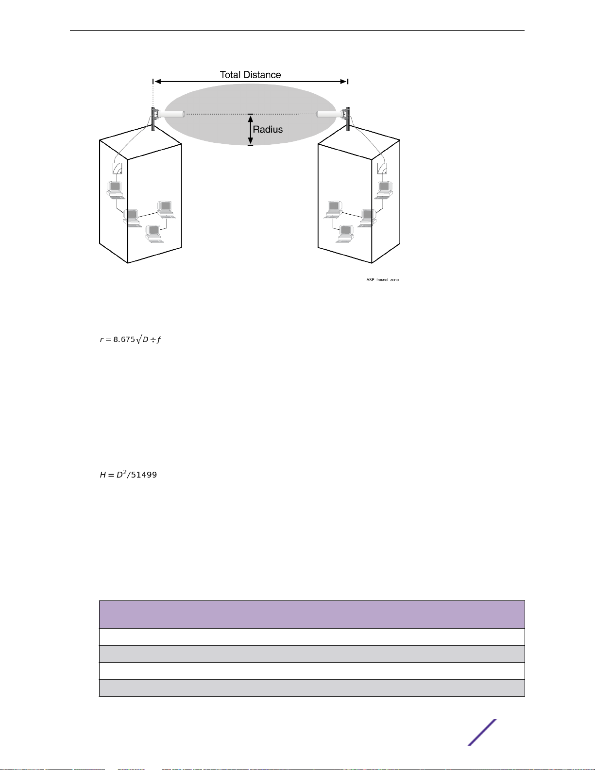
Figure 1: Fresnel Zone and Line of Sight Clearance
AP Site Preparation
The radius can be calculated using the following formula:
Where
D = Distance between the antennas in kilometers
f = Frequency in GHz
60% of the Fresnel Zone has to be clear of obstructions to be line of sight. In addition to the Fresnel
Zone height requirement, earth curvature may become a factor in paths longer than 2 Km. The
additional antenna height can be calculated using the following formula:
Where
D = Distance between the antennas in kilometers
H = Height required to overcome earth curvature
and Table 5 on page 10 lists typical antenna height requirements.
Table 4: Typical Antenna Height Requirements—2.4 GHz
Distance between Tx and
Rx antennas (km)
Fresnel Zone radius
(meters)
Earth curvature (meters) Minimum antenna height
requirements (meters)
2 7.9 0.08 7.98
5 12.5 0.49 12.99
10 17.67 1.94 19.61
15 21.64 4.37 26.01
ExtremeWireless™ External Antenna with Wave 2 9
Page 10

Table 4: Typical Antenna Height Requirements—2.4 GHz (continued)
Distance between Tx and
Rx antennas (km)
20 25 7.77 32.77
25 28 12.14 40.14
30 30.6 17.48 48.08
Fresnel Zone radius
(meters)
Earth curvature (meters) Minimum antenna height
requirements (meters)
Table 5: Typical Antenna Height Requirements—5 GHz
Distance between Tx and
Rx antennas (km)
2 5.22 0.08 5.3
5 8.24 0.49 8.73
10 11.67 1.94 13.61
15 14.3 4.37 18.67
Fresnel Zone radius
(meters)
Earth curvature (meters) Minimum antenna height
requirements (meters)
AP Site Preparation
20 16.5 7.77 24.27
25 18.46 12.14 30.6
30 20.22 17.48 37.7
For optimal performance, ensure that the antenna products you choose, in combination with the height
of the antenna installation above ground, provide sucient clearance to allow your antenna installation
to cover the distance between the two sites.
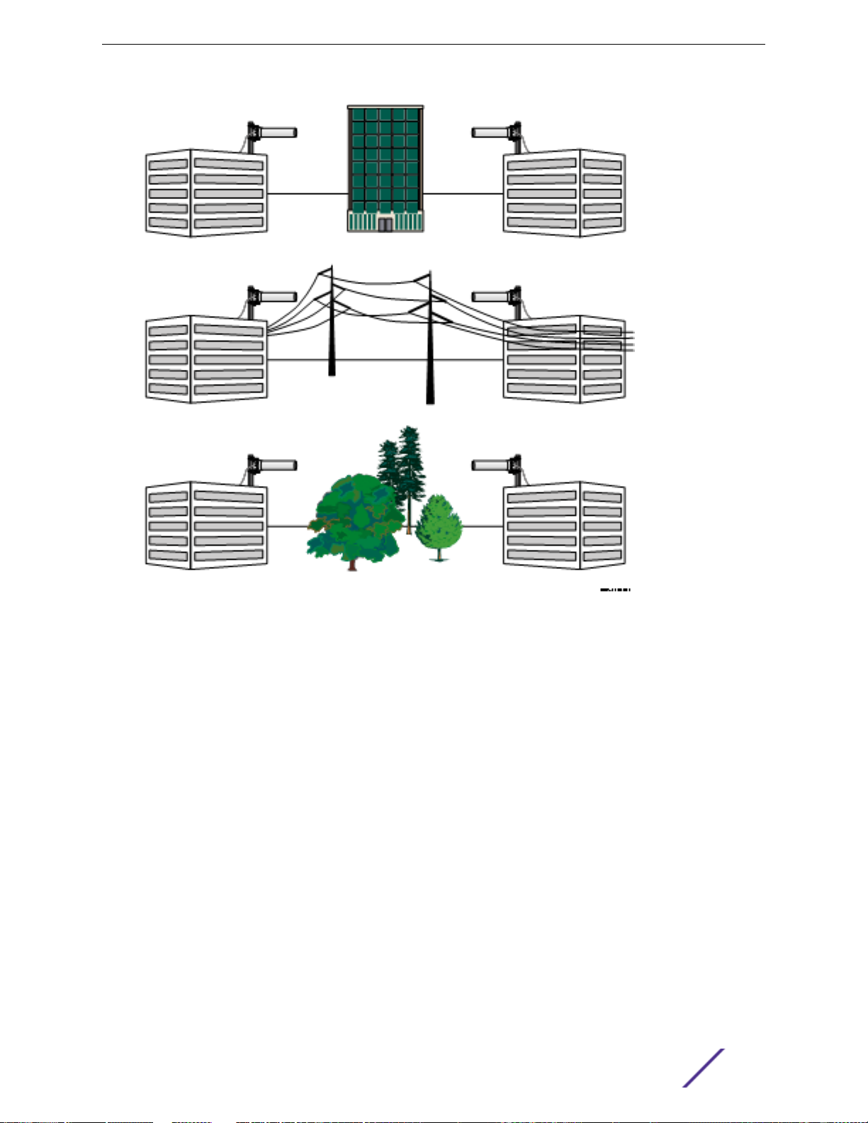
Obstacles within the line of sight can significantly reduce the distance and performance. Obstructions
include neighboring buildings, trees, and power lines, as shown in the following figure:
ExtremeWireless™ External Antenna with Wave 2 10
Page 11
AP Site Preparation
Figure 2: Potential Obstacles to Line of Sight (not to scale)
Additional Location Requirements
This section describes other requirements to meet before installing the outdoor antennas.
Lightning Protection
•
A lightning rod must be placed close to the antenna mast or wall bracket. This is required to protect
the antenna from direct lightning strikes.
Grounding System
•
Direct earth grounding of the antenna and the lightning protector is necessary to protect the
installation from lightning and the build-up of static electricity. The wireless device and the lightning
protector must be connected to the same earth ground using separate grounds. The antenna and
the mounting structure require separate grounds to the same earth ground, using an equipotential
bonding conductor. Check with a certified antenna installer, or local electrician, to make sure the
antenna is properly grounded.
Ensure that the cable between the antenna and lightning protector is at least 0.9 meters (3 feet)
away from high-voltage or high-current cable. For more information about the lightning protector,
see Grounding System on page 24.
ExtremeWireless™ External Antenna with Wave 2 11
Page 12

Antenna Height
•
If you are mounting the antenna on a roof, the antenna must have minimum clearance as specified in
Table 4 on page 9 and Table 5 on page 10.
If you are mounting the directional antenna to a wall of a building, it must be high enough to achieve
a clear line of sight. Mounting an omni-directional antenna to the side of a building can cause signal
reflection and reduce distance.
Note
The installer is responsible for local building codes.
AP Placement
•
The AP should be located indoors, and connected to the outdoor antenna using the shortest cable
possible to reduce the loss of the cable.
Antenna Models
AP Site Preparation
This section provides a brief description of the antenna models oered by Extreme Networks for use
with ExtremeWireless APs. Table 6 lists antennas supported by the 39xx series APs. Table 7 on page 14
lists antennas for the AP38xx series . Refer to Antenna Installation on page 23 for antenna installation
instructions.
ExtremeWireless™ External Antenna with Wave 2 12
Page 13

Table 6: AP39xx External Antennas Listed by AP
AP Site Preparation
Antenna Gain
(dBi)
Extreme Networks
Wireless AP
3965e
The AP3965
uses Standard
Polarity, Type-N
Plug and Type N
Jack connectors.
For optional
cables, see Table
49 on page 140.
Antenna Model Type Description Frequency
(GHz)
30711 (WS-AO-DQ05120N) Outdoor 120 degree,
Sector
30712 (WS-AO-5Q04060N) Outdoor 60 degree,
Sector
30713 (WS-AO-2Q05060N) Outdoor 60 degree,
Sector
30714 (WS-AO-DE07025N) Outdoor Sector 2.4G/5G 7.5 6.5
30715 (WS-AO-DE13025N) Outdoor Sector 2.4G/5G 13 12
30716 (WS-AO-5Q05025N) Outdoor Sector 5G N/A 4.5
30717 (WS-AO-5Q11025N) Outdoor Sector 5G N/A 11.5
30718 (WS-AO-DE10055N) Outdoor Sector 2.4G/5G 10.5 7.5
30720 (WS-AO-DE07100N) Outdoor Panel. Includes
eight, five-foot
adapter cables.
30724 (WS-AODQ04360N)
WS-AO-5D23009N (WSAO-5D23009N)
Outdoor Omni 2.4G/5G 5.5 6
Outdoor 9 degree, panel,
dual
polarization,
point-to-point.
Includes two,
five-foot adapter
cables
2.4G/5G 5.5 5.5
5G N/A 4
2.4G 5 N/A
2.4G/5G 7 6
5G N/A 23
2.4G 5G
3935e
30702 (WS-AI-DQ05120) Indoor 120 degree,
Sector
2.4G/5G 5.5 5.5
The AP3935 uses
Reverse Polarity
SMA connectors.
ExtremeWireless™ External Antenna with Wave 2 13
30703 (WS-AI-5Q04060) Indoor 60 degree,
Sector
30704 (WS-AI-2Q05060) Indoor 60 degree,
Sector
30705 (WS-AI-DE07025) Indoor 25 degree,
Sector
30706 (WS-AI-5Q05025) Indoor 25 degree,
Sector
30707 (WS-AI-DE10055) Indoor 55 degree,
Sector
30709 (WS-ANT-2DIP-4) Indoor DIPOLE 2.4G 4.66 N/A
30710 (WS-ANT-5DIP-4) Indoor DIPOLE 5G N/A 4.67
WS-AI-DQ04360 (WS-AIDQ04360)
Indoor Ceiling Mount
Omni
5G N/A 4
2.4G 5 N/A
2.4G/5G 7.5 6.5
5G N/A 4.5
2.4G/5G 10.5 7.5
2.4G/5G 4 7
Page 14

The following table lists existing antennas supported by AP38xx models.
Table 7: AP38xx External Antennas Listed by AP
AP Site Preparation
Antenna Gain
(dBi)
Extreme Networks
Wireless AP
AP3865e
The AP3865 uses
Standard
Polarity, Type-N
Plug and Type N
Jack connectors.
For optional
cables see Table
49 on page 140.
Antenna Model Type Description Frequency
(GHz)
WS-AO-DT05120N Outdoor 120 degree,
sector, triplefeed, MIMO.
WS-AO-5D23009N Outdoor 9 degree, panel,
dual polarization,
point-to-point.
Includes two,
five-foot adapter
cables.
WS-AO-DX13025N Outdoor 27/30 degree,
panel, six-feed.
WS-AO-DX10055N Outdoor 55 degree, panel,
six-feed.
WS-AO-DS02360N3 Outdoor Omni baton,
single feed, 3
pack.
WS-AO-2DIPN3 Outdoor Dipole, 3 pack. 2.4 5 N/A
WS-AO-5DIPN3 Outdoor Dipole, 3 pack. 5.0 N/A 7
WS-AO-DX07180N Outdoor 180 degree,
panel, six feed.
Includes six, five-
foot adapter
cables.
2.3–2.7/4.9–6.1 5 5
5.15–5.875 N/A 23
2.4–2.5/5.15–
5.875
2.4–2.5/5.15–
5.875
2.4–2.5/5.15–
5.875
2.4–2.5/5.15–
5.875
2.4G 5G
12 11
9 8
2 2
7 7
AP3825e
The AP3825 uses
Reverse Polarity
SMA connectors.
ExtremeWireless™ External Antenna with Wave 2 14
WS-ANT-2DIP-3 Indoor MIMO; Single-
band, 3
connector ports.
WS-ANT-5DIP3 Indoor MIMO; Single-
band, 3
connector ports.
WS-AI-DX02360 Indoor MIMO; Dual-
band.
WS-AI-DT05120 Indoor MIMO, Sector,
Dual-band, 3
connector ports.
WS-AI-DX10055 Indoor MIMO; Sector,
Dual-band.
WS-AI-DX07025 Indoor MIMO; Sector;
Dual-band.
2.4 3 N/A
5.0 N/A 3
2.4–2.5/5.15–
5.85
2.3–2.7/4.9–6.1 5 2.1
2.4–2.5/5.1–5.9 10 6
2.4–2.5/5.1–5.9 6.5 5.5
2 N/A
Page 15

Table 7: AP38xx External Antennas Listed by AP (continued)
AP Site Preparation
Antenna Gain
(dBi)
Extreme Networks
Wireless AP
AP3805e
The AP3805 uses
Reverse Polarity
SMA connectors.
Antenna Model Type Description Frequency
(GHz)
WS-AI-DQ04360 Indoor MIMO; Dual-
band, 802.11n, 4
connector ports.
WS-AI-DD05120 Indoor MIMO, Dual-
Feed, 120 degree
sector.
WS-ANT-2DIP2 Indoor Dipole, 2 pack. 2.4 3 N/A
WS-ANT-5DIP2 Indoor Dipole 2 pack. 5.0 3 N/A
2.4-2.5/4.9-5.9 4 7
2.4/5.0 6 5
Cable Options
Extreme Networks oers optional low-loss, outdoor and indoor cables. The outdoor cables are
watertight cables to connect the outdoor APs to an antenna. The optional outdoor cables have a
Standard Polarity Type-N Plug and Type-N Jack. The indoor cables have a Reverse Polarity SMA-Type
connector. Carefully determine the distance between the locations where you intend to mount the
external antenna to ensure that you order the right cable length.
Note
Extreme Networks recommends using PFP600 (Cables: WS–CAB–L600C25N and WS–CAB–
L600C50N) for 5 GHz.
2.4G 5G
For more information about antenna cables, see:
Table 49 on page 140
•
Indoor Antenna Cables with Reverse Polarity SMA-Type Connectors on page 141
•
Contacting an Antenna Installation Company
Have an antenna installation professional install the outdoor antennas. The antenna installer provides
the expertise to properly install, secure, and ground your antenna. The following checklists describe
tasks that the installer may need to perform.
Note
The antenna installation professional should be licensed or certified in accordance with local
regulations.
Mounting Requirements
Determine the type of mounting that is required (tripod, wall mount, and so on).
•
Determine the guy wires needed. Typically, three guy wires are needed for each 3 meter (10 foot)
•
section of the mast; for example, 6 meters (20 feet) of mast requires six guy wires.
ExtremeWireless™ External Antenna with Wave 2 15
Page 16

AP Site Preparation
Line of Sight
Determine the mounting location for the antenna.
•
Ensure that the back of the antenna is clear.
•
Ensure that remote and local antennas can see each other.
•
Ensure that no obstacles are in the direct path or within the defined zone of the two sites.
•
Consider whether any Radio Frequency (RF) interference is present.
•
Installation Requirements
Determine the best location for the AP.
•
Determine the length of cable required from the antenna to the AP.
•
Ensure the location has an accessible Ethernet connection.
•
Determine the distance between buildings.
•
You may need to provide the following distances when contacting the antenna installation company.
•
Distance to Provide to Antenna Installation Company
Coverage area required (wireless infrastructure network
configuration):
Height of building A:
Height of building B:
All possible obstacles that can interfere with the defined
radius.
ExtremeWireless™ External Antenna with Wave 2 16
Page 17

2 ExtremeWireless APs That Support
External Antennas
Determining the Location of the AP
ExtremeWireless AP3965e
ExtremeWireless AP3935e
ExtremeWireless AP3865e
ExtremeWireless AP3825e
ExtremeWireless AP3805e
This section provides an illustration of each ExtremeWireless AP with information about how to
determine where to place the AP.
Determining the Location of the AP
The ideal location to install your ExtremeWireless AP must satisfy the following requirements:
For indoor APs, the location must be indoors to protect the AP from extreme weather conditions,
•
excessive heat and humidity, and to keep the unit free from vibration and dust. For a list of
ExtremeWireless indoor APs and the supported antennas, see External Antennas for Use with
Indoor APs on page 93.
The location must provide a connection to the network backbone via an Ethernet LAN cable going
•
to a hub, bridge, or directly into a patch panel. An AP in a WDS does not require an Ethernet
connection since backhaul is established over the wireless medium.
For an outdoor AP, the location must be close to where the low-loss antenna cable will enter the
•
building. For a list ofExtremeWireless outdoor APs and the supported antennas, see External
Antennas for Use with Outdoor APs on page 41.
Extreme Networks recommends using PFP240 or PFP400 cable for 2.4 GHz and PFP600 for 5GHz.
•
For more information, see Cable Specifications on page 141.
External Wave 2 antennas have built-in lightening protectors.
•
ExtremeWireless AP3965e
The AP3965 enables you to extend your wireless LAN beyond the boundaries of indoor locations. It is
resistant to harsh outdoor conditions and extreme temperatures. Using the advanced full mesh wireless
distribution feature of the wireless LAN, the AP3965 can extend your wireless LAN to outdoor locations
without Ethernet cabling. A mounting bracket is available to enable quick and easy mounting of the
AP3965 to walls and poles. The ExtremeWireless 3965e oers 8 connections for external antennas.
The AP3965 is an 802.11ac AP that supports 802.11a/802.11g and 802.11b legacy devices. It is delivered in
a rugged enclosure. The AP3965 interoperates fully with the wireless LAN, including support for
wireless VoWLAN, branch oce mode, availability and mobility features. The AP3965i provides eight
ExtremeWireless™ External Antenna with Wave 2 17
Page 18
ExtremeWireless APs That Support External Antennas
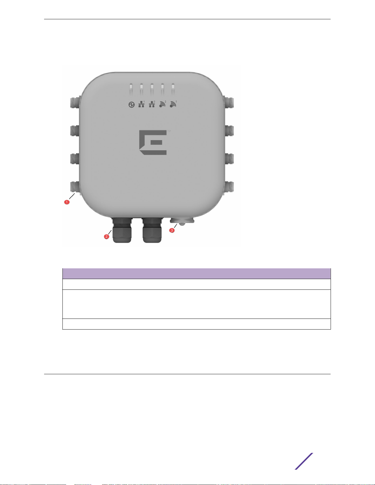
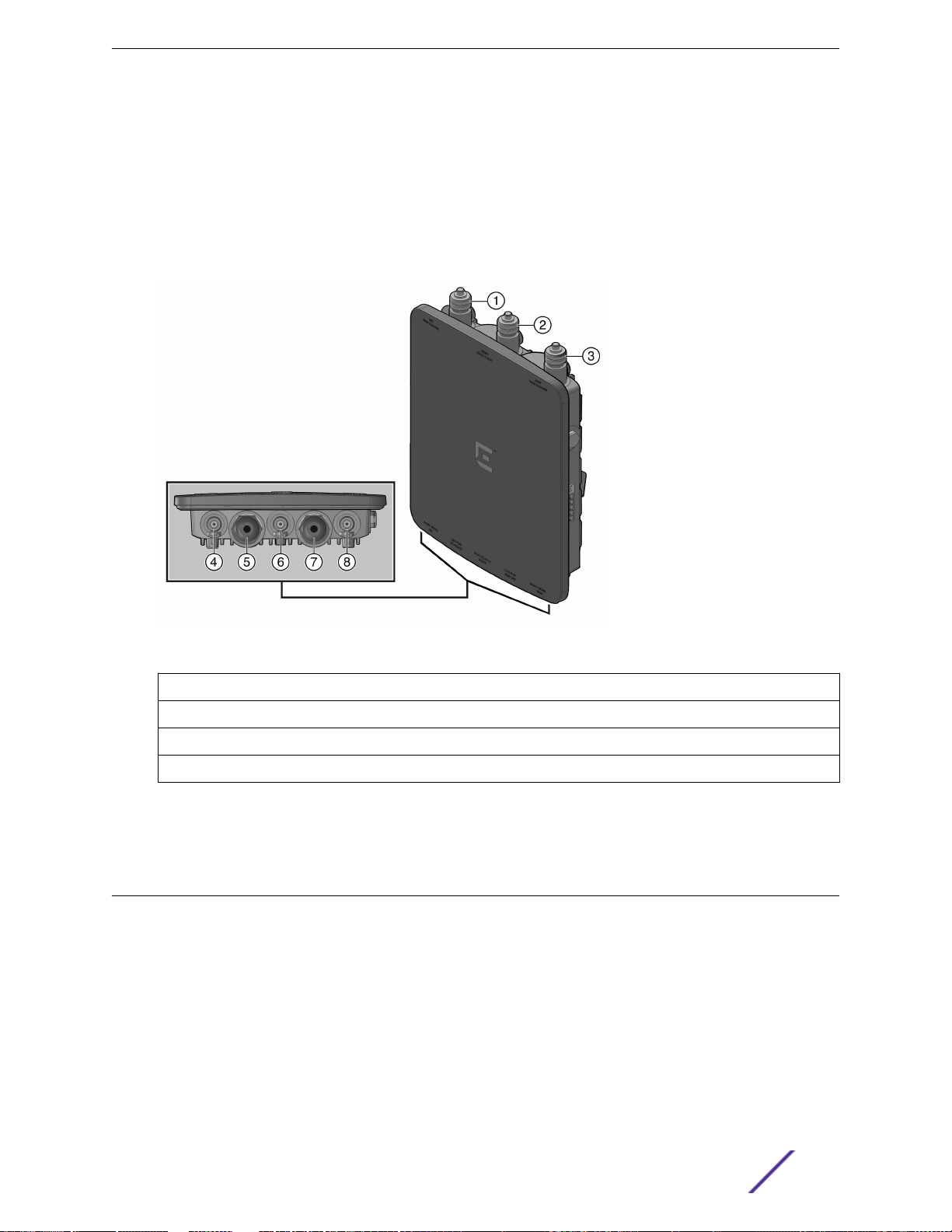
internal antennas, and the AP3965e (Figure 3) supports a variety of external antennas, providing range
and coverage versatility. For a list of supported antennas for the AP3965, see Table 6 on page 13.
Figure 3: AP3965e Front View
Component
1 4 Radio Antenna Connection ports on each side
2 LAN Ports (POE)
3 Console Port and Reset Button
Refer to the ExtremeWireless AP3965i & AP3965e Installation Guide for information about AP
installation procedures.
Description
LAN 1 PDE Port
•
LAN 2 PSE Port output of DC48V, 0.26A
•
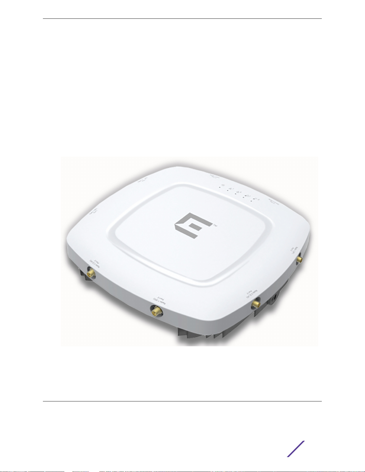
ExtremeWireless AP3935e
The AP3935 is designed to extend your Wireless LAN around indoor locations. The AP3935 supports
the 802.11ac and 802.11n wireless standards, with full backward compatibility with legacy 802.11a, and
802.11b/g devices.
The AP3935 interoperates fully with Wireless LANs, including support for VoWLAN, branch oce mode,
guest services, RTLS, availability, and mobility features. The operating temperature: 0 - 50C. The
AP3935 oers the following features:
ExtremeWireless™ External Antenna with Wave 2 18
Page 19
ExtremeWireless APs That Support External Antennas
Support for two MIMO 4x4 (up to four 802.11ac spatial streams).
•
Two single band radios for dual-band, concurrent operation, optimized for indoor antenna coverage:
•
5 GHz (Radio 1) in any of the following modes: IEEE802.11ac, a/b/g and/or n
•
2.4 GHz (Radio 2) in any of the following modes: IEEE802.11ac, a/b/g and/or n
•
Enclosed in a rectangular, compact case.
•
Can be mounted on walls and drop/suspended ceilings.
•
Provides 80 MHz Bandwidth at 2.4/5 GHz operation (Channel Bonding).
•
Power is provided through two Ethernet ports (LAN port). This is the preferred method of powering
•
the AP on ceiling and wall installations. The AP3935 can also be powered by an external DC power
supply by plugging the supply’s input jack into the DC-In port.
The ExtremeWireless 3935e oers eight connections for external antennas.
•
For a list of supported antennas for the AP3935, see Table 6 on page 13.
Figure 4: AP3935e Top View
Refer to the ExtremeWireless AP3935i & AP3935e Installation Guide for more information about AP
installation procedures.
ExtremeWireless AP3865e
The WS-AP3865e is designed to extend your wireless LAN around indoor locations. It operates fully
with the Extreme Networks wireless LAN, including support for Extreme Networks wireless VoWLAN,
branch oce mode, availability and mobility features. This AP operates in 802.11ac and 802.11n mode
ExtremeWireless™ External Antenna with Wave 2 19
Page 20
ExtremeWireless APs That Support External Antennas
and also support 802.11a/802.11g and 802.11b standard legacy devices. It includes mounting brackets. It
can be powered directly through the LAN using Power over Ethernet (PoE), or by an external adapter.
Using the advanced full mesh wireless distribution feature of the wireless LAN, the WS-AP3865e can
extend your wireless LAN to outdoor locations without Ethernet cabling. It is resistant to harsh outdoor
conditions and extreme temperatures.
For a list of supported antennas for the AP3865, see Table 7 on page 14.
Figure 5: WS-AP3865e Top/Bottom View
Radio 2—Left Antenna (2.4 GHz) 5 LAN 1 Port (POE Input)
1
2 Radio 1—Middle Antenna (5.0 GHz) 6 Radio 2—Middle Antenna (2.4 GHz)
3 Radio 2—Right Antenna (2.4 GHz) 7 LAN 2 Port (Pwr Out)
4 Radio 1—Left Antenna (5.0 GHz) 8 Radio 1—Right Antenna (5.0 GHz)
Refer to the IdentiFi Wireless WS-AP3865e Installation Guide for information about AP installation
procedures.
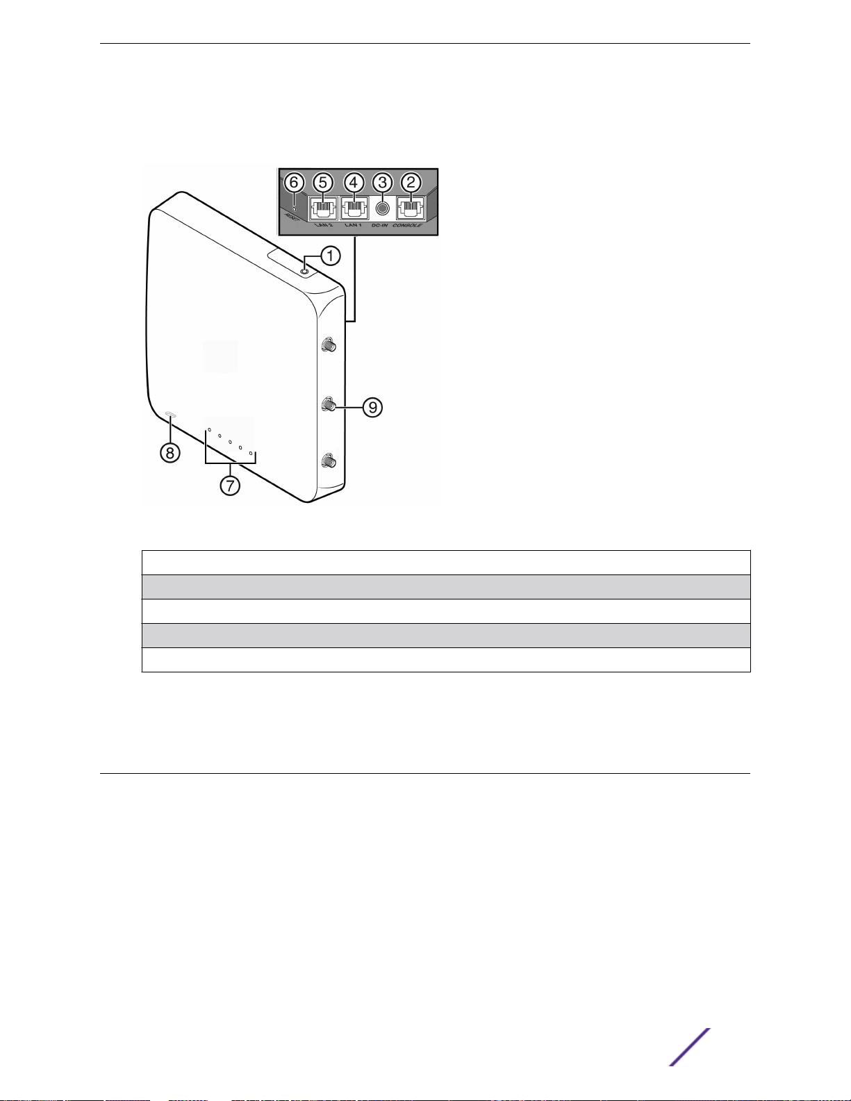
ExtremeWireless AP3825e
The AP3825e is designed to extend your wireless LAN around indoor locations. It operates fully with the
Extreme Networks wireless LAN, including support for Extreme Networks wireless VoWLAN, branch
oce mode, availability and mobility features. This AP operates in 802.11ac and 802.11n mode and also
support 802.11a/802.11g and 802.11b standard legacy devices. It includes mounting brackets. It can be
powered directly through the LAN using Power over Ethernet (PoE), or by an external adapter.
(110/240V AC/DC)
WS-AP3825e supports two MIMO 3x3 (up to three 802.11ac spatial streams). It provides two single band
radios for dual-band, concurrent operation, optimized for indoor antenna coverage.It provides 40MHz
Bandwidth at 2.4/5 GHz operation (Channel Bonding).
ExtremeWireless™ External Antenna with Wave 2 20
Page 21
ExtremeWireless APs That Support External Antennas
The WS-AP3825e has dual Ethernet (LAN) ports for fault-tolerant network connection and failover.
For a list of supported antennas for the WS-AP3825e, see Table 7 on page 14.
Figure 6: AP3825e External Antenna Cable Installation
(not used) 6 Reset Switch
1
2 Console Port 7 LEDs
3 External DC Power Supply Port 8 (bottom) Kensington Lock Slot
4 LAN Port 1 9 External antenna connectors (6 R-SMA)
5 LAN Port 2
Refer to the IdentiFi Wireless WS-AP3825i & WS-AP3825e Installation Guide for information about AP
installation procedures.
ExtremeWireless AP3805e
The WS-AP3805 is designed to extend your wireless LAN around indoor locations. It operates fully with
the Extreme Networks wireless LAN, including support for Extreme Networks wireless VoWLAN, branch
oce mode, availability and mobility features. This AP operates in 802.11ac and 802.11n mode and also
support 802.11a/802.11g and 802.11b standard legacy devices. It includes mounting brackets. It can be
powered directly through the LAN using Power over Ethernet (PoE), or by an external adapter. An
optional, external 12V DC power supply (WS-PSI12V-MR1) may be ordered separately to power the WSAP3805 from a standard AC wall outlet.
For a list of supported antennas for the WS-AP3805e, see Table 7 on page 14.
ExtremeWireless™ External Antenna with Wave 2 21
Page 22
ExtremeWireless APs That Support External Antennas
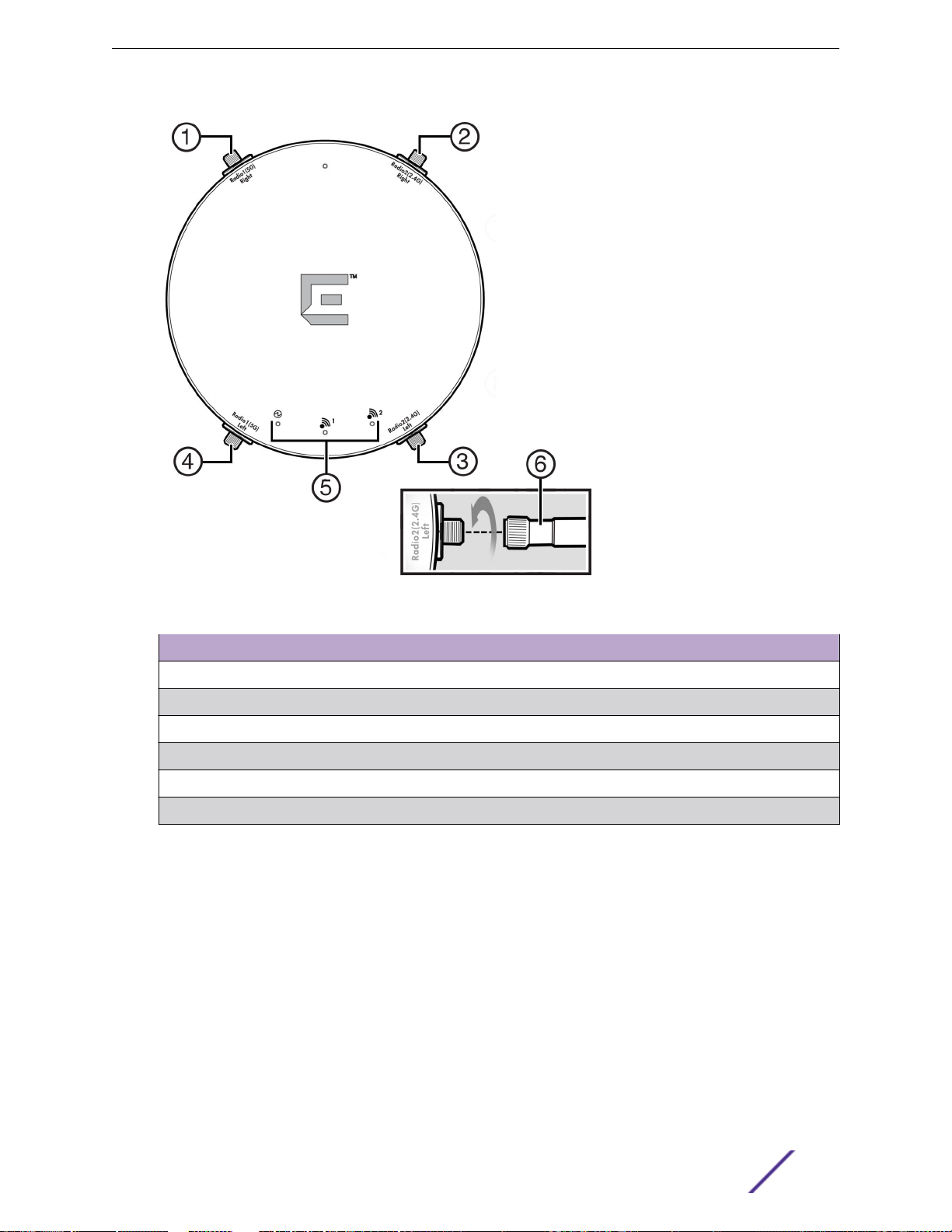
Figure 7: AP3805e External Antenna Cable Installation
Component
1 Antenna Port Radio 1 - Right (5 GHz)
2 Antenna Port Radio 2 - Right (2.4 GHz)
3 Antenna Port, Radio 2 - Left (2.4GHz,)
4 Antenna Port, Radio 1 - Left (5 GHz
5 LEDs
6 External Antenna (1 of 4)
Description
Refer to the IdentiFi Wireless WS-AP3805i & WS-AP3805e Installation Guide for the AP3805e
installation procedures.
ExtremeWireless™ External Antenna with Wave 2 22
Page 23

3 Antenna Installation
Outdoor Antenna Kits
Installation Overview
Grounding System
Mounting the Antenna
Cable Installation Guidelines
Routine Maintenance
This section provides the information necessary for a professional antenna installer to install the
Extreme Networks antennas.
Warning
Antennas should only be installed by a qualified antenna installer. The antenna installation
professional should be licensed or certified in accordance with local regulations.
Do not install the antenna in wet, windy, icy, or otherwise unsafe weather conditions.
Outdoor Antenna Kits
The ExtremeWireless outdoor antenna kits do NOT provide the following items, which may be
necessary to install the antenna:
Mast or other antenna support structure
•
Guy wires
•
All cables or other hardware necessary for a complete grounding system
•
Waterproof tape
•
Note
It is the customer’s responsibility to ensure that an outdoor antenna installation complies with
local radio regulations.
Installation Overview
Note
Not all antennas described in this chapter can be used by every wireless access point. Refer to
Antenna Models on page 12 to determine if your access point supports the specified antenna.
The installation process is summarized in the following steps. The following sections in this chapter
provide additional details.
1 Make sure the APs are mounted and configured as specified.
2 Plan and implement a grounding system (if applicable) that meets local electrical codes and safety
standards.
ExtremeWireless™ External Antenna with Wave 2 23
Page 24

Antenna Installation
3 Install the lightning protector (if applicable).
4 Provide and install an antenna support structure as necessary. Make sure that the support structure
is connected to the grounding system (if applicable).
5 Connect the exposed metal connectors of the low-loss antenna cable to the grounding system (if
applicable).
6 Mount the antenna to the support structure.
7 Connect the antenna cables.
8 Route and connect the low-loss antenna cable to the lightning protector that has been installed
indoors (if applicable).
9 Connect the cable assembly from the AP to the lightning protector (if applicable).
10 After verifying that the communications link is fully operational, secure all cables and use
weatherproofing tape to seal all outdoor connectors.
Grounding System
Direct earth grounding of the antenna and the lightning protector is necessary to protect the installation
from lightning and the build-up of static electricity.
Caution
The antenna mast, ExtremeWireless AP, and lightning protector must be connected to the
same earth ground (with separate grounds), using an equipotential bonding conductor. A
good electrical connection should be made to one or more ground rods using at least a
6AWG ground wire and non-corrosive hardware. The grounding system must comply with the
National Electrical Code and safety standards that apply in your country. Always check with a
qualified electrician to determine whether your outdoor installation is properly grounded.
The grounding system must satisfy the following requirements:
The antenna mast, ExtremeWireless AP, and lightning protector must be connected to the same
•
earth ground using an equipotential bonding conductor.
The antenna and the mounting structure require a separate earth ground connection. Check with a
•
certified antenna installer to make sure the antenna is properly grounded.
Ensure that the cable between the antenna and lightning protector is at least 0.9 meters (3 feet)
•
away from high-voltage or high-current cable.
A good electrical connection must be made to one or more ground rods, using at least a 10 AWG
•
ground wire and noncorrosive hardware.
The grounding system must comply with electrical codes and safety standards that apply in your
•
locality.
Have a qualified electrician verify that your outdoor installation is properly grounded.
•
Caution
A properly installed safety grounding system is necessary to protect your ExtremeWireless
outdoor installation from lightning strikes and static electricity build-up.
Mounting the Antenna
This section includes requirements and mounting guidelines for the ExtremeWireless outdoor antennas.
ExtremeWireless™ External Antenna with Wave 2 24
Page 25

Antenna Installation
Selecting a Mast
Note
You must supply your own mast on which to mount an ExtremeWireless antenna.
ExtremeWireless antennas do not come with masts.
To minimize the influence of obstacles, signal interference or reflections, install the antenna at least 2
meters (6 feet) away from all other antennas.
If you need to mount multiple antennas on a single mast, alternate the mounting of directional antennas
for vertical and horizontal polarization.
In subfreezing conditions, the communications link could fail if an antenna is exposed to ice buildup or
covered with snow.
The mast must satisfy the following requirements:
The mast must be constructed of sturdy, weatherproof, noncorrosive material such as galvanized or
•
stainless steel construction pipe.
Antenna mast length must be sucient to allow an antenna height at least 1.5 meters (5 feet) above
•
the roof peak. If the roof is metal, the antenna height should be a minimum of 3 meters (10 feet)
above the roof.
Antenna Polarization
It does not matter what type of polarization you choose for your ExtremeWireless antennas as long as
the antenna at one end of the communications link is mounted in the same plane as the antenna at the
other end.
Vertical polarization is standard for the ExtremeWireless 14 dBi directional antenna.
To minimize the influence of cross-talk between antennas, you might need to mount the antenna for
horizontal polarization when:
Multiple antennas are mounted on the same antenna mast.
•
The wireless link transmissions cross another radio beam from a neighboring installation.
•
Approved Antennas for the ExtremeWireless APs
Extreme Networks APs using certified external antennas must comply with local laws and regulations.
An approval may be required by the local regulatory authorities. Antenna Models on page 12 lists and
describes the optional antennas that have been tested and approved for use with the APs compatible
with external antennas.
To mount the antennas on the AP3825e, refer to the following sections.
ExtremeWireless™ External Antenna with Wave 2 25
Page 26

Antenna Installation
Table 8: AP3825e Approved Antennas
External Antenna Mounting Instructions
WS-ANT-2DIP-3 Mounting Antenna Model WS-ANT-2DIP-3
WS-ANT-5DIP-3 Mounting Antenna Model WS-ANT-5DIP-3
WS-AI-DX10055 Mounting Antenna Model WS-AO-DX10055N and
Related Antenna Models
WS-AI-DT05120 Mounting Antenna Model WS-AI-DT05120
WS-AI-DX02360 Mounting Antenna Model WS-AI-DX02360
WS-AI-DX07025 and WS-AI-DX07025N Mounting Antenna Models WS-AO-DX13025 and WS-
AI-DX07025
To mount the antennas on the AP3865e, refer to the following sections.
Table 9: AP3865e Approved Antennas
External Antenna Mounting Instructions
WS-AO-2DIPN3 Mounting Antenna Model WS-AO-2DIPN3
WS-AO-5DIPN3 Mounting Antenna Model WS-AO-5DIPN3
WS-AO-DX10055N Mounting Antenna Model WS-AO-DX10055N and WS-
AO-DX10055
WS-AO-DT05120N Mounting Antenna Model WS-AI-DT05120
WS-AO-DX02360N3 Mounting Antenna Model WS-AI-DX02360
WS-AO-5D23009N Mounting Antenna Model WS-AO-5D23009
WS-AO-DX13025N Mounting Antenna Models WS-AO-DX13025 and WS-
AI-DX07025
WS-AO-DX07180N Mounting Antenna Model WS-AO-DX07180N
For specific information on antennas that support the AP3805e and information on each Wave 2
antenna, refer to Antenna Specifications on page 41.
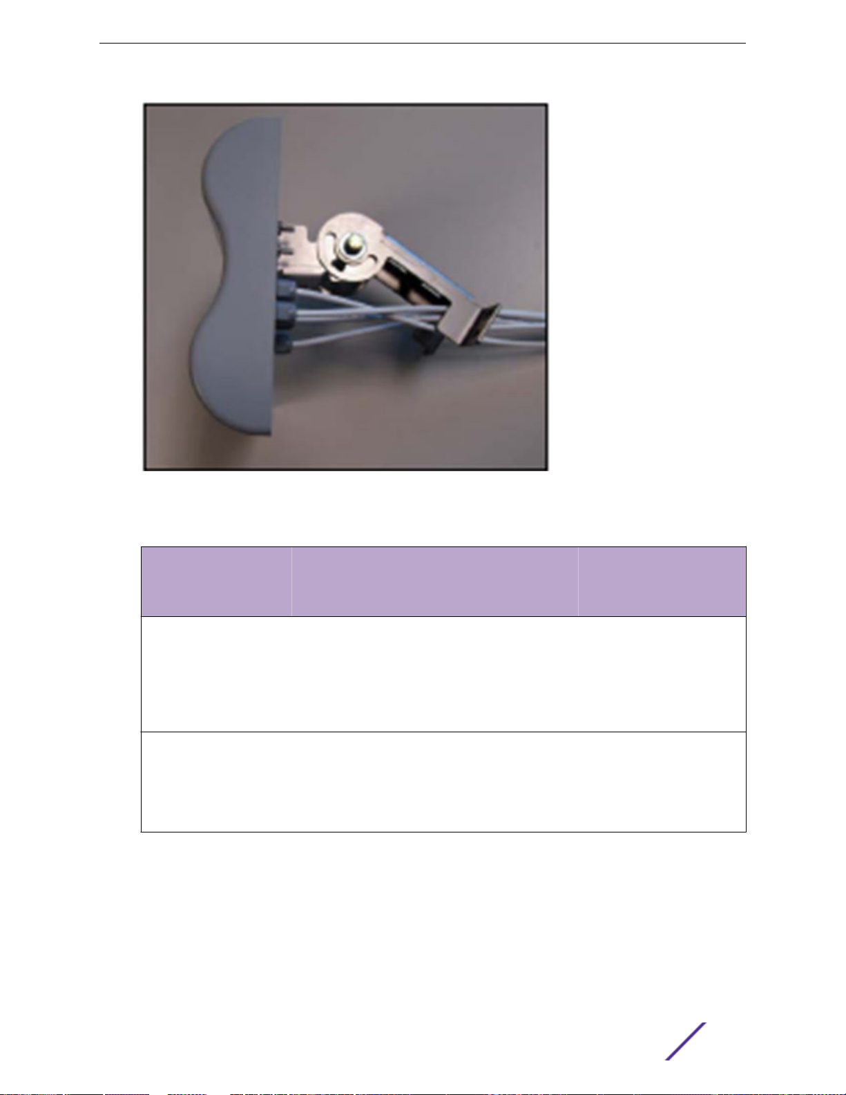
Mounting Antenna Model WS-AO-DX10055N and Related Antenna Models
The WS-AO-DX10055N is dual-band six port (three for each band) MIMO antennas providing spatial
diversity coverage of 2.4–2.5 GHz WiFi and 5.1–5.9 GHz WiFi WiMAX broadband wireless frequencies in
a low profile housing. This antenna provides optimal coverage for areas or events with a large number
of mobile data users. It designed for outdoor installations utilizing 802.11n multi-band wireless LAN
access point radios. The following figure shows the WS-AO-DX10055N antenna. Table 10 lists the cable
and connector type for each antenna.
Note
The WS-AO-DX10055N and the WS-AI-DX10055 are the same antenna. The WS-AODX10055N is intended for outdoor use. The WS-AI-DX10055 is intended for indoor use.
ExtremeWireless™ External Antenna with Wave 2 26
Page 27
Antenna Installation
Figure 8: WS-AO-DX10055N Antenna
Table 10: Antenna Cable and Connector Information
Antenna Model T
WS-AO-DX10055N O
WS-AI-DX10055 I
Mounting Instructions: WS-AO-DX10055N, WS-AI-DX10055
Cable Type Cable Length Connector Type
y
p
e
RG316 39 inches Standard Polarity, Type N Plug
u
t
d
o
o
r
RG316 39 inches Reverse Polarity SMA Plug
n
d
o
o
r
Connector
The antenna includes a fully adjustable mount for pipe or wall mounting. Hardware for wall mounting is
not included in the kit. The table below lists the parts required for installation. The mount allows the
antenna to be vertically or horizontally polarized.
ExtremeWireless™ External Antenna with Wave 2 27
Page 28
Antenna Installation
Table 11: Mount Kit Contents
Item Quantity Description
1 4 Nut, 5/16-18,1/2" Hex. 17/64" Thick, Steel Grade 2,NlZN Trivalent
2 1 Bolt, Carriage, 5/16-18 x 3/4
3 1 Bracket, Mount. Antenna
4 1 Bolt, 5/16-18 x 2 1/2", Hex Head, Steel, Nl ZN Trivalent
5 1 Tube, Aluminum, 0.37" ID x 0.50" OD x 1.415"
6 4 Washer, Flat, 5/16, 5/8" OD x 11/32" ID x 0.065", Steel, Zinc
7 4 Washer, Split Lock, 5/16, Steel Grade 2, Nl ZN Trivalent
8 1 Bracket, Mount, Antenna
9 1 Screw, Hex Head, 1/4-20 x 2.0,18-8 SS
10 1 Nut, Hex, Nylock, 1/4-20 UNC
11 1 V-Bolt, 5/16-18 UNC-2A, Med. Carbon Steel, Nl ZN Trivalent
12 4 Washer, 1/4 Flat, Steel Grade 2, Nl ZN Trivalent
13 4 Nut, Hex 1/4-20, Steel Grade 2, Nl ZN Trivalent
14 4 Washer, 1/4, Split Lock, Steel Grade 2, Nl ZN Trivalent
Tools required for attaching mount to antenna and securing to pole:
7/16 inch wrench
•
1/2 inch wrench
•
To install the antenna:
1 Remove the antenna and mount kit from the packaging, and remove the mount kit contents from its
packaging. Confirm that the mount kit includes the contents listed in Table 11.
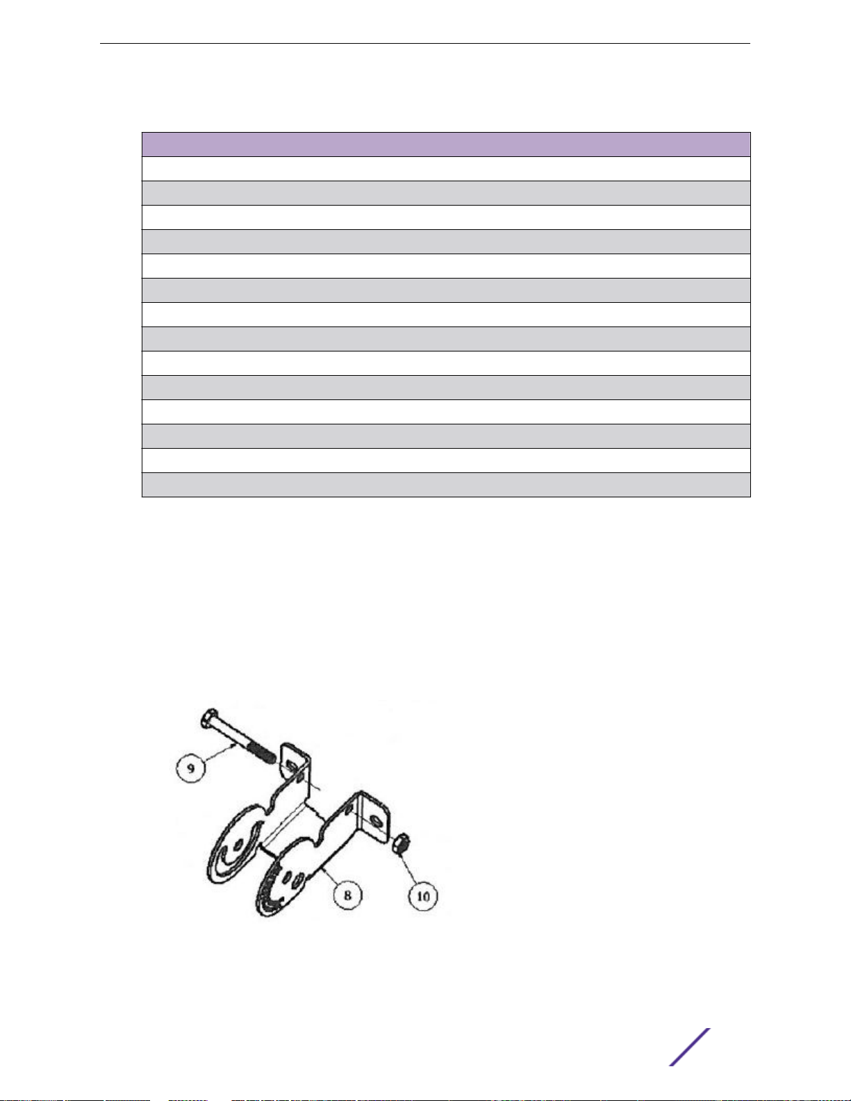
2 Install 1/4-20 x 2" screw (item 9) into the bracket (item 8) with one hole on each flange. Secure with
lock nut (item 10). Tighten only until the nut contacts the bracket. Do not over tighten.
Figure 9: Install Screw in Bracket
ExtremeWireless™ External Antenna with Wave 2 28
Page 29
Antenna Installation
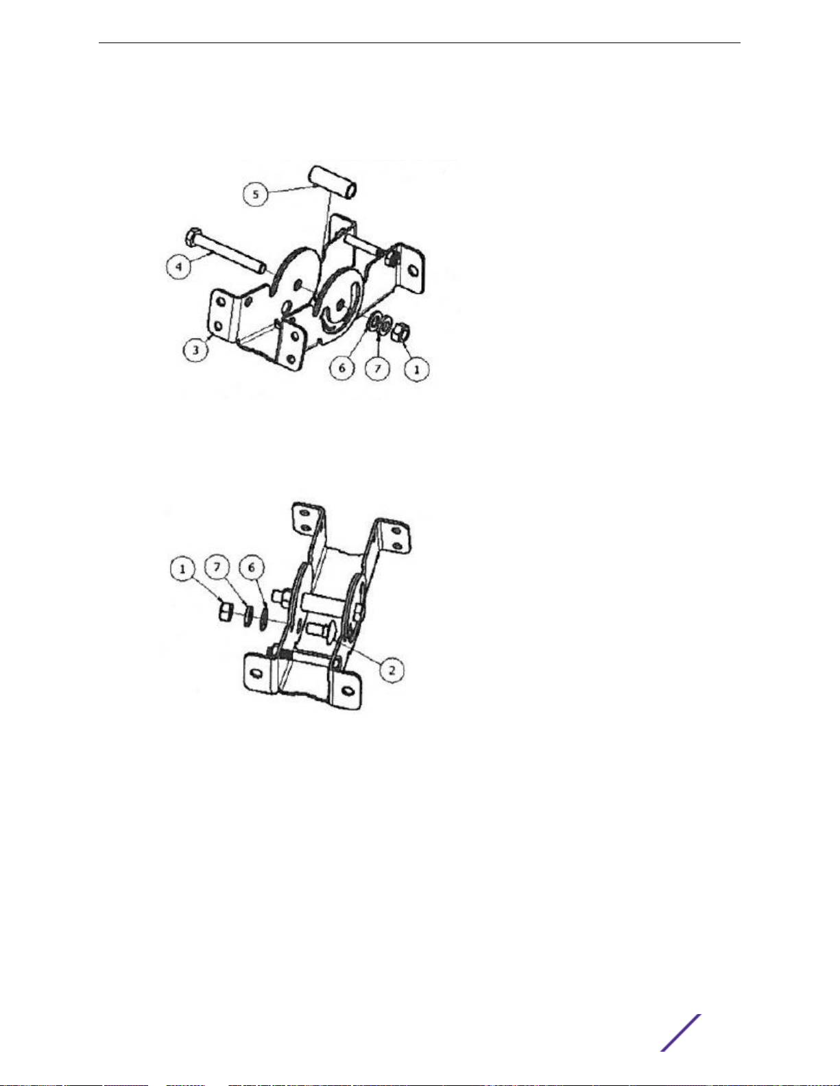
3 Assemble the brackets item 3) with the arc toward the outside. Slide aluminum spacer (item 5) in
between and feed pivot bolt (item 4) through. Install washers and nut (items 1, 6, 7), but do not
tighten at this point.
Figure 10: Assemble the Brackets
4 Assemble locking carriage bolt (item 2) and attach washers and nut (items 1, 6, 7), but do not
tighten at this point.
Figure 11: Install Carriage Bolt
ExtremeWireless™ External Antenna with Wave 2 29
Page 30
Antenna Installation
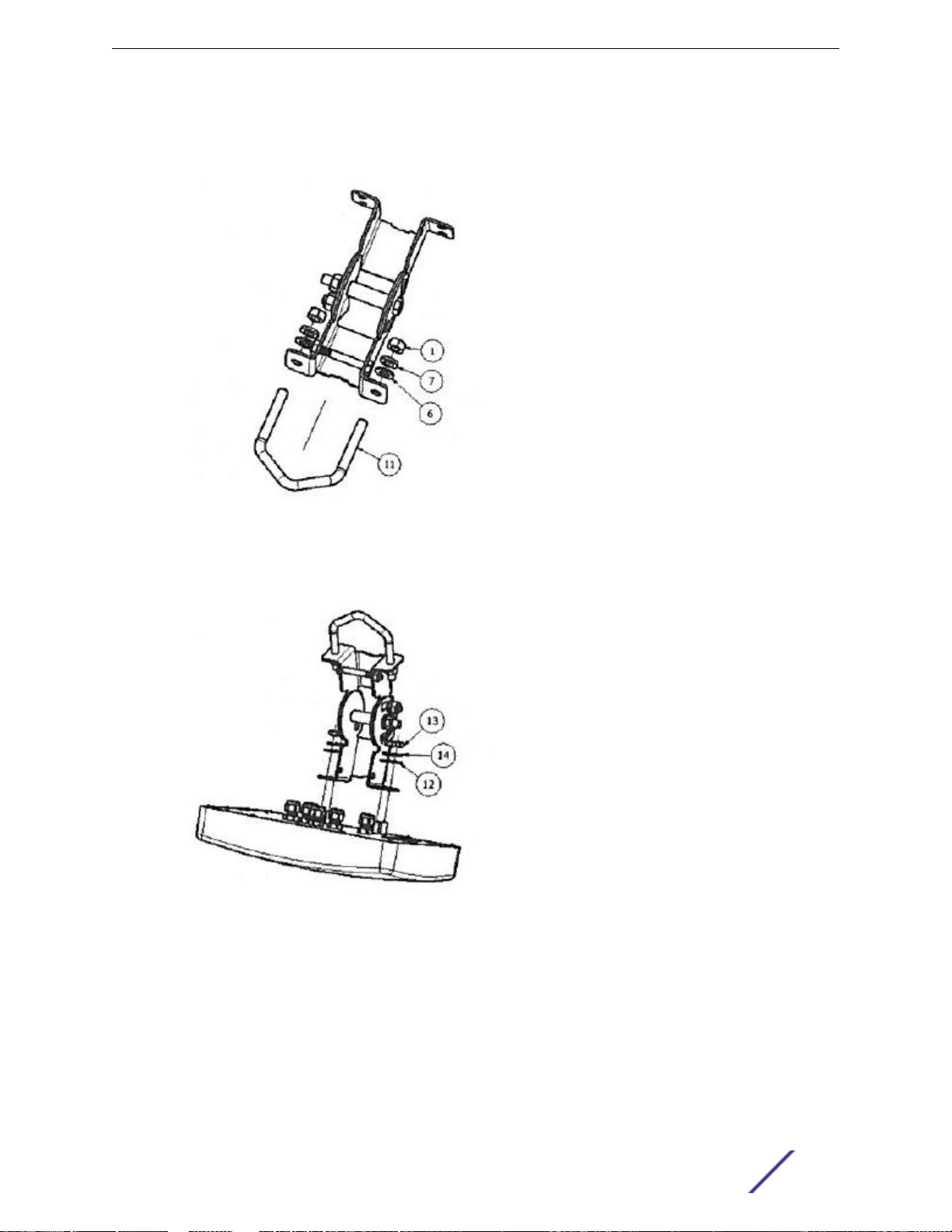
5 If mounting hole can be slid over pipe, install V-bolt (item 11) into the pole side bracket (one hole in
flange) and loosely secure the washers and nuts (items 1, 6, 7). Otherwise, locate bracket assembly
on pipe, and feed the V-bolt through and secure with washers and nut.
Figure 12: Install V-bolt
6 Attach mount assembly to the antenna using the 1/4-20 hardware in the hardware kit (Items 12, 13,
14). Mount can go on in either direction.
Figure 13: Attach Assembly
ExtremeWireless™ External Antenna with Wave 2 30
Page 31

7 Set down tilt angle and tighten pivot and carriage bolts.
Figure 14: Set Angle
Antenna Installation
ExtremeWireless™ External Antenna with Wave 2 31
Page 32

Mounting Antenna Model WS-ANT-2DIP-3
Antenna Installation
Figure 15: WS-ANT-2DIP-3 Antenna
To install the antenna, secure the antenna in place by tightening the single nut.
Note
The AP3825 supports up to six antennas. One 3-pack of WS-ANT-2DIP-3 antennas and one 3pack of WS-ANT-5DIP-3 antennas.
ExtremeWireless™ External Antenna with Wave 2 32
Page 33

Mounting Antenna Model WS-ANT-5DIP-3
Antenna Installation
Figure 16: WS-ANT-5DIP-3 Antenna
To install the antenna, secure the antenna in place by tightening the single nut.
Note
The AP3825 supports up to six antennas. One 3-pack of WS-ANT-2DIP-3 antennas and one 3pack of WS-ANT-5DIP-3 antennas.
Mounting Antenna Model WS-AO-2DIPN3
You can mount the WS-AO-2DIPN3 antenna directly to the AP3865e.
Note
This antenna is packaged in 3 antennas to a package (3-pack).
ExtremeWireless™ External Antenna with Wave 2 33
Page 34

Antenna Installation
Figure 17: Mounting the WS-AO-2DIPN3 Antenna to the AP3865e
Antenna 4 Standard polarity Type-N jack
1
2 Nut 5 AP3865e
3 Standard polarity Type-N plug 6 Sealing tape (recommended, but not supplied)
To install the antenna:
1 Secure the antenna in place by tightening the single nut (item 2).
2 Seal the connection between the Type-N jack (item 4) of the AP3865e and the Type-N plug (item 3)
of the antenna by wrapping a layer of sealing tape (item 6).
Note
The AP3865e supports one package of WS-AO-2DIPN3 antennas (one 3-pack) as shown
in Figure 17 on page 34.
Mounting Antenna Model WS-AO-5DIPN3
You can mount the WS-AO-5DIPN3 antenna directly to the AP3865e. The AP3865e supports one
package of three WS-AO-5DIPN3 antennas (one 3-pack).
ExtremeWireless™ External Antenna with Wave 2 34
Page 35

Antenna Installation
Figure 18: Mounting the WS-AO-5DIPN3 Antenna to the AP3865e
Antenna 4 Standard polarity Type-N jack
1
2 Nut 5 AP3865e
3 Standard polarity Type-N plug 6 Sealing tape (recommended, but not supplied)
To install the antenna:
1 Secure the antenna in place by tightening the single nut (item 2).
2 Seal the connection between the Type-N jack (item 4) of the AP3865e and the Type-N plug (item 3)
of the antenna by wrapping a layer of sealing tape (item 6).
Mounting Antenna Model WS-AO-DX07180N
The WS-AO-DX07180N is a dual-band, six port (three for each band) Sector antenna providing
coverage of 2.4 GHz and 5 GHz broadband wireless frequencies in a low profile housing. The antenna
provides optimal coverage for areas or events with a large number of mobile data users. It is designed
for outdoor installations using 802.11a/b/g/n multi-band wireless LAN access point radios. Table 12 lists
connector and cable information for the antenna.
The mounting kit includes a heavy duty articulating mount for a wall or mast mount installation. UL 94HB materials are used for compliance with strict building code safety specifications.
ExtremeWireless™ External Antenna with Wave 2 35
Page 36

Antenna Installation
Figure 19: Outdoor Antenna WS-AO-DX07180N with Mounting Bracket
Table 12: Antenna Cables and Connectors
Antenna Model Cable Type Cable Length Qty Connector Type
WS-AO-DX07180N PFP240UF 5 ft 6 Standard Polarity, Type N Plug
Mounting Antenna Models WS-AO-DX13025 and WS-AI-DX07025
The WS-AO-DX13025 is designed for outdoor installations, and the WS-AI-DX07025 is designed for
indoor installations. Both antennas use 802.11n multi-band wireless LAN access point radios. Table 13
lists the connector type for each antenna.
Figure 20: WS-AO-DX13025 and WS-AI-DX07025 Antennas
ExtremeWireless™ External Antenna with Wave 2 36
Page 37

Antenna Installation
Table 13: Antenna Connector Connectors
Antenna Model Type Connector Type
WS-AO-DX13025 Outdoor Reverse Polarity, Type N Plug
WS-AI-DX07025 Indoor Reverse Polarity, Type SMA Plug
Mounting Antenna Model WS-AI-DX02360
The WS-AI-DX02360 is a dual-band six port omni-directional MIMO antenna. With separate ports that
are designed to operate at 2.4 GHz and 5 GHz. Each of the MIMO antenna R-SMA ports can be
connected to an access point by means of a coax pigtail.
The antenna is designed for ceiling mounting in indoor locations.
Figure 21: WS-AI-DX02360 Antenna
Mounting the WS-AI-DX02360
For best results, mount the WS-AI-DX02360 at ceiling level near the center of the coverage area. A lineof-sight path between the antenna and active floor locations work best. Avoid mounting next to a
column or vertical support that could create a shadow zone and reduce coverage to one portion of the
room.
A threaded post on the back side of the Antenna and a mounting nut (supplied with the antenna) are
the primary mounting configuration when access is available to both sides of the mounting surface,
such as suspended ceiling tile.
ExtremeWireless™ External Antenna with Wave 2 37
Page 38

Antenna Installation
Figure 22: WS-AI-DX02360 Mounting Post and Mounting Nut
To install the antenna in a suspended ceiling:
1 Mark the desired mounting location on the suspended ceiling tile and cut a 40 mm (1.57 in) hole in
the tile.
2 Feed the six antenna cables through the hole and press the antenna to the ceiling tile.
3 Secure the antenna with the mounting nut, as shown in the previous figure.
4 Connect the cables to an access point by means of coax pigtails.
The cables are marked by colored heat-shrink wrap and labels, indicating the three cables for 2.4 GHz
connections and the three cables for 5 GHz connections.
A rubber locking gasket is also supplied with the antenna. Use this gasket with the mounting nut only
when mounting the antenna to a hard surface.
If access to the back of the mounting surface is not available, use the two mounting holes shown in the
previous figure to attach the antenna with #8 screws and expanding anchors (not supplied).
Mounting Antenna Model WS-AO-DT05120 and Related Antenna Models
The WS-AO-DT05120 and related models is a 2.4 and 5 GHz dual-band sector antenna that can be
mounted in an outdoor location. The WS-AI-DT05120 antenna model is intended for indoor locations.
Each antenna has three connectors and is especially designed for MIMO APs. Table 14 shows connector
and cable information. These antennas can also be mounted on a wall or on a pole.
ExtremeWireless™ External Antenna with Wave 2 38
Page 39

Figure 23: WS-AO-DT05120 and Related Antenna Models
Table 14: Antenna Cable and Connector Information
Antenna Model Cable Type Cable Length Connector Type
Antenna Installation
WS-AO-DT05120 RG316 32 inches Reverse Polarity, Type N Jack
WS-AO-DT05120-1 RG316 32 inches Reverse Polarity, Type N Plug
WS-AO-DT05120N RG316 32 inches Standard Polarity, Type N Plug
WS-AI-DT05120 RG316 32 inches Reverse Polarity SMA Plug
Wave 2 Antennas
For specific information on antennas that support the AP3805e and information on each AP39XX series
antenna, refer to Antenna Specifications on page 41.
Cable Installation Guidelines
The cable configuration that you use to connect an AP to an antenna varies. Use the following sections
as guidelines for cabling your AP to an antenna.
Do not install the cable in tight positions, as bending or applying excessive force to the connectors may
damage the antenna cable. Always allow the cable to bend naturally around corners.
The low-loss antenna cable must be secured along its complete length. Do not allow any part of the
cable to hang free. This is particularly important for cable parts that are installed outdoors. The antenna
cables and cable connectors are not designed to withstand excessive force:
Do not use connectors as cable grips to pull cable through raceways or conduits.
•
Do not use cable connectors to support the weight of the cable during or after installation.
•
Do not use tools to tighten connectors (finger-tighten only).
•
ExtremeWireless™ External Antenna with Wave 2 39
Page 40

Antenna Installation
Connecting the Cables
Take the following steps to connect cables:
1 Secure the low-loss cable to the mast such that the cable connectors do not support the full weight
of the cable.
Caution
To avoid damage to the antenna cable and connectors, do not use tools to tighten cable
connectors.
Precaución: para evitar daños en los cables y el conector de la antena, no use herramientas
para apretar los conectores.
Achtung: Verwenden Sie kein Werkzeug zum Anziehen der Kabelanschlüsse. Durch
Werkzeug können das Kabel und die Anschlüsse beschädigt werden.
2 Provide a drip-loop at the bottom of the low-loss cable just before it enters the building.
3 Prior to securing the cable along its complete length, refer to Optimizing Outdoor Point-to-Point
Antenna Placement on page 40. If required, adjust the direction of the antenna.
4 After fully testing the installation, tighten the antenna mounting nuts to lock the antenna into its
position.
Caution
To prevent damage, avoid over-tightening the connectors, nuts, and screws used to mount
the antenna.
Precaución: evite apretar demasiado los conectores, tuercas y tornillos usados para
instalar la antena, para no dañarlos.
Achtung: Beugen Sie Schaden vor, indem Sie die Anschlüsse, Muttern und Schrauben für
die Antenne nicht zu fest anziehen.
5 Secure the cable along its complete length. Do not allow any part of the cable to hang free.
6 Using waterproof stretch tape, seal all outdoor connectors.
Optimizing Outdoor Point-to-Point Antenna Placement
If an AP is connected to an outdoor directional antenna, the antenna must point directly at the antenna
for the other AP. A misaligned antenna can decrease the signal level or prevent communications.
Aligning an omni-directional antenna is less critical due to its wide radiation pattern. For optimal
performance, make sure the antennas are properly aligned by using a pair of binoculars to point the
antennas at each other.
Routine Maintenance
Routine maintenance is required for each lightning protector in your outdoor antenna installation.
Maintenance involves replacing the lightning protector at some interval depending on the lightning/
transient discharge activity in your area.
Note
Contact a local antenna installation company to determine the maintenance schedule for each
lightning protector in your outdoor antenna installation.
ExtremeWireless™ External Antenna with Wave 2 40
Page 41

4 Antenna Specifications
External Antennas for Use with Outdoor APs
External Antennas for Use with Indoor APs
This section lists the specifications and radiation patterns for the external antennas supported by
various ExtremeWireless AP models. The antenna specifications are organized in this section by their
design capability:
Strictly outdoor
•
Combined indoor/outdoor
•
Strictly indoor
•
ExtremeWireless antenna part numbers/descriptions indicate the indoor/outdoor capability of the
antenna:
WS-AO: outdoor
•
WS-AIO: indoor/outdoor
•
WS-AI: indoor
•
External Antennas for Use with Outdoor APs
The following antennas are intended for use with outdoor APs only:
Table 15: Outdoor Antennas
Antenna Part Number Supported APs
30711 (WS-AO-DQ05120N) AP3965e
30712 (WS-AO-5Q04060N) AP3965e
30713 (WS-AO-2Q05060N) AP3965e
30714 (WS-AO-DE07025N) AP3965e
30715 (WS-AO-DE13025N) AP3965e
30716 (WS-AO-5Q05025N) AP3965e
30717 (WS-AO-5Q11025N) AP3965e
30718 (WS-AO-DE10055N) AP3965e
30720 (WS-AO-DE07100N) AP3965e
30724 (WS-AO-DQ04360N) AP3965e
WS-AO-DS02360N3 AP3865e
WS-AO-DX07180N AP3865e
WS-AO-DT05120 AP3865e
WS-AO-DT05120N AP3865e
ExtremeWireless™ External Antenna with Wave 2 41
Page 42

Antenna
Table 15: Outdoor Antennas (continued)
Antenna Part Number Supported APs
WS-AO-DX13025 AP3865e
WS-AO-DX13025N AP3865e
WS-AO-DX10055N AP3825e, AP3865e
WS-AO-2DIPN3 AP3865e
WS-AO-5DIPN3 AP3865e
30711 (WS-AO-DQ05120N)
This 4-port sector antenna can be used for 802.11ac MIMO applications. The four ports can be used
individually or in combination with legacy 802.11 access points.
Specifications
Figure 24: Outdoor Antenna 30711 (WS-AO-DQ05120N) with Mounting Bracket
ExtremeWireless™ External Antenna with Wave 2 42
Page 43

Antenna
Specifications
Table 16: 30711 (WS-AO-DQ05120N) Specifications
Value
Specification 2.4 GHz 5GHz
Frequency 2.4-2.5 GHz 5.1-5.9 GHz
Gain 5-5.5 dBi 4.5-5.5 dBi
Vertical Beamwidth 90° 65°
Horizontal Beamwidth 100° 80°
VSWR 1.5-2.0
Operating Temperature Range -40°C to +70°C
Polarization Dual-slant linear +-45
Weight .45kg
Mounting Style Wall or pipe mount
Power 20 watts
Specifications
Dimensions 200 x 200 x 34 mm
Nominal Impedance 50 ohms
Radiation Patterns
Figure 25: 2.4 GHz Horizontal Pattern
ExtremeWireless™ External Antenna with Wave 2 43
Page 44

Antenna
Specifications
Figure 26: 2.4 GHz Vertical Pattern
Figure 27: 5GHz Horizontal Pattern
ExtremeWireless™ External Antenna with Wave 2 44
Page 45

Antenna
Specifications
Figure 28: 5GHz Vertical Pattern
30712 (WS-AO-5Q04060N)
This 4-port sector antenna can be used for 802.11ac MIMO applications. The four ports can be used
individually or in combination with legacy 802.11 access points.
ExtremeWireless™ External Antenna with Wave 2 45
Page 46

Antenna Specifications
Figure 29: Outdoor Antenna 30712 (WS-AO-5Q04060N)
Specifications
Table 17: 30712 (WS-AO-5Q04060N) Specifications
Specification Value
Frequency 5.15-5.85 GHz
Gain 3-4 dBi
Vertical Beamwidth 33°
Horizontal Beamwidth 50°
VSWR 1.5-2.0
Operating Temperature Range -40°C to +70°C
Polarization Dual-slant linear +-45°
Weight .45kg
Mounting Style Wall or pipe mount
Power 20 watts
Dimensions 200 mm x 200 x 34mm
Nominal Impedance 50 ohms
ExtremeWireless™ External Antenna with Wave 2 46
Page 47

Radiation Patterns
Antenna
Specifications
Figure 30: 5 GHz Radiation Patterns
30713 (WS-AO-2Q05060N)
This 4-port sector antenna can be used for 802.11ac MIMO applications. The four ports can be used
individually or in combination with legacy 802.11 access points.
ExtremeWireless™ External Antenna with Wave 2 47
Page 48

Antenna Specifications
Figure 31: Outdoor Antenna 30713 (WS-AO-2Q05060N) with Mounting Bracket
Specifications
Table 18: 30713 (WS-AO-2Q05060N) Specifications
Specification Value
Frequency 2.4-2.5 GHz
Gain 4-5 dBi
VSWR 2.0 Max (1.5 Typ)
Vertical Beamwidth 34°
Horizontal Beamwidth 73°
Operating Temperature Range -40°C to +70°C
Polarization Dual-slant, linear +-45°
Weight 0.45 kg
Mounting Style Wall or pipe mount
Power 20 watts
Dimensions 7.9 in x 7.9 in x 1.25 in (200 mm x 200 mm x 34 mm)
Nominal Impedance 50 ohms
ExtremeWireless™ External Antenna with Wave 2 48
Page 49

Radiation Patterns
Antenna
Specifications
Figure 32: 2.4 GHz Horizontal Pattern
Figure 33: 2.4 GHz Vertical Pattern
30714 (WS-AO-DE07025N)
This dual-band 8-port sector antenna can be used for 802.11ac MIMO applications. The antenna covers
both 2.4-2.5 GHz and 5.1-5.9 GHz in one radome. The eight ports can be used individually or in
combination for use with legacy 802.11 access points.
ExtremeWireless™ External Antenna with Wave 2 49
Page 50

Figure 34: Outdoor Antenna 30714 (WS-AO-DE07025N)
Specifications
Antenna Specifications
Table 19: 30714 (WS-AO-DE07025N) Specifications
Value
Specification 2.4 GHz 5GHz
Frequency 2.4-2.5 GHz 5.1-5.9 GHz
Gain 6.5-7.5 dBi 5.5-6.5 dBi
Vertical Beamwidth 43° 37°
Horizontal Beamwidth 31° 29°
VSWR < 2.25:1
Operating Temperature Range -30°C to +80°C
Polarization Dual linear
Weight 2.27kg
Mounting Style Wall or pipe mount
Power 25 watts
Dimensions 305 mm x 305 x 110.5mm
Nominal Impedance 50 ohms
ExtremeWireless™ External Antenna with Wave 2 50
Page 51

Radiation Patterns
Antenna
Specifications
Figure 35: 2.4GHz Horizontal Pattern
Figure 36: 2.4GHz Vertical Pattern
ExtremeWireless™ External Antenna with Wave 2 51
Page 52

Antenna
Specifications
Figure 37: 5GHz Horizontal Pattern
Figure 38: 5GHz Vertical Pattern
30715 (WS-AO-DE13025N)
This dual-band 8-port sector antenna can be used for 802.11ac MIMO applications. The antenna covers
both 2.4-2.5 GHz and 5.1-5.9 GHz in one radome. The eight ports can be used individually or in
combination for use with legacy 802.11 access points.
ExtremeWireless™ External Antenna with Wave 2 52
Page 53

Specifications
Figure 39: Outdoor Antenna 30715 (WS-AO-DE13025N)
Antenna Specifications
Table 20: 30715 (WS-AO-DE13025N) Specifications
Value
Specification 2.4 GHz 5GHz
Frequency 2.4-2.5 GHz 5.1-5.9 GHz
Gain 12-13 dBi 11-12 dBi
Vertical Beamwidth 43° 37°
Horizontal Beamwidth 31° 29°
VSWR < 2.25:1
Operating Temperature Range -30°C to +80°C
Polarization Dual linear
Weight 2.27kg
Mounting Style Wall or pipe mount
Power 25 watts
Dimensions 305 mm x 305 x 110.5mm
Nominal Impedance 50 ohms
ExtremeWireless™ External Antenna with Wave 2 53
Page 54

Radiation Patterns
Antenna
Specifications
Figure 40: 2.4GHz Horizontal Pattern
Figure 41: 2.4GHz Vertical Pattern
ExtremeWireless™ External Antenna with Wave 2 54
Page 55

Antenna
Specifications
Figure 42: 5GHz Horizontal Pattern
Figure 43: 5GHz Vertical Pattern
30716 (WS-AO-5Q05025N)
The four port sector antennas can be used for 802.11ac MIMO applications that operate in the 5.1-5.9
GHz frequency range. The four elements can be used individually or in combination for use with legacy
802.11 access points.
ExtremeWireless™ External Antenna with Wave 2 55
Page 56

Figure 44: Outdoor Antenna 30716 (WS-AO-5Q05025N)
Specifications
Antenna Specifications
Table 21: 30716 (WS-AO-5Q05025N) Specifications
Specification Value
Frequency 5.1-5.9 GHz
Gain 3.5 - 4.5 dBi
Vertical Beamwidth 40°
Horizontal Beamwidth 30°
VSWR < 2.0:1
Operating Temperature Range -30°C to +80°C
Polarization Dual linear
Weight 1.36 kg
Mounting Style Wall or pipe mount
Power 25 watts
Dimensions 18.1 x 24.9 x 12.9 cm
Nominal Impedance 50 ohms
ExtremeWireless™ External Antenna with Wave 2 56
Page 57

Radiation Patterns
Antenna
Specifications
Figure 45: 5 GHz Horizontal Pattern
Figure 46: 5GHz Vertical Pattern
30717 (WS-AO-5Q11025N)
The four port sector antennas can be used for 802.11ac MIMO applications that operate in the 5.1-5.9
GHz frequency range. The four elements can be used individually or in combination for use with legacy
802.11 access points.
ExtremeWireless™ External Antenna with Wave 2 57
Page 58

Figure 47: Outdoor Antenna 30717 (WS-AO-5Q11025N)
Specifications
Antenna Specifications
Table 22: 30717 (WS-AO-5Q11025N) Specifications
Specification Value
Frequency 5.1-5.9 GHz
Gain 10.5 - 11.5 dBi
Vertical Beamwidth 40°
Horizontal Beamwidth 30°
VSWR < 2.0:1
Operating Temperature Range -30°C to +80°C
Polarization Dual linear
Weight 1.36 kg
Mounting Style Wall or pipe mount
Power 25 watts
Dimensions 18.1 x 24.9 x 12.9 cm
Nominal Impedance 50 ohms
ExtremeWireless™ External Antenna with Wave 2 58
Page 59

Radiation Patterns
Antenna
Specifications
Figure 48: 5 GHz Horizontal Pattern
Figure 49: 5GHz Vertical Pattern
30718 (WS-AO-DE10055N)
The dual-band, 8 port, sector antenna provides spatial diversity coverage of 2.4 and 5 GHz broadband
wireless frequencies in a low profile housing. Designed for outdoor installations utilizing 802.11ac MIMO
applications. The elements can be used individually or in combination for use with legacy 802.11 access
points.
ExtremeWireless™ External Antenna with Wave 2 59
Page 60

Figure 50: 30718 (WS-AO-DE10055N)
Specifications
Antenna Specifications
Table 23: 30718 (WS-AO-DE10055N) Specifications
Value
Specification 2.4 GHz 5GHz
Frequency 2.4-2.5 GHz 5.1-5.9 GHz
Gain 10-10.5 dBi 6-7.5 dBi
Vertical Beamwidth 44° 43°
Horizontal Beamwidth 51° 53°
VSWR < 2.25:1
Operating Temperature Range -30°C to +80°C
Polarization Dual linear
Weight 2.3kg
Mounting Style Wall or pipe mount
Power 25 watts
Dimensions 305 mm x 305 x 110.5mm
Nominal Impedance 50 ohms
ExtremeWireless™ External Antenna with Wave 2 60
Page 61

Radiation Patterns
Antenna
Specifications
Figure 51: 2.4 GHz Horizontal Pattern
Figure 52: 2.4 GHz Vertical Pattern
ExtremeWireless™ External Antenna with Wave 2 61
Page 62

Antenna
Specifications
Figure 53: 5GHz Horizontal Pattern
Figure 54: 5GHz Vertical Pattern
30720 (WS-AO-DE07100N)
The dual-band, 8 port, sector antenna provides spatial diversity coverage of 2.4 and 5 GHz broadband
wireless frequencies in a low profile housing. Designed for outdoor installations utilizing 802.11n multiband wireless LAN access point radios, it provides coverage for venues with many mobile data users.
ExtremeWireless™ External Antenna with Wave 2 62
Page 63

Antenna Specifications
Figure 55: Outdoor Antenna 30720 (WS-AO-DE07100N) and Mounting Bracket
Specifications
Table 24: WS-AO-DE07100N Specifications
Value
Specification 2.4 GHz 5GHz
Frequency 2.4-2.5 GHz 5.1-5.9 GHz
Gain 5.7-7 dBi 4-6 dBi
Vertical Beamwidth 90° 60°
Horizontal Beamwidth 100° 75°
VSWR < 2.0:1
Operating Temperature Range -40°C to +70°C
Polarization Vertical
Weight 1.3kg
Mounting Style Wall or pipe mount
Power 25 watts
Dimensions 18.1 x 39.9 x 5.1 cm
Nominal Impedance 50 ohms
ExtremeWireless™ External Antenna with Wave 2 63
Page 64

Radiation Patterns
Antenna Specifications
Figure 56: 2.4 GHz Radiation Patterns
ExtremeWireless™ External Antenna with Wave 2 64
Page 65

Antenna
Specifications
Figure 57: 5 GHz Radiation Patterns
30724 (WS-AO-DQ04360N)
The 30724 dual-band, 4-port, omni-directional antenna can be used for 802.11ac MIMO applications. The
antenna covers both 2.4-2.5 GHz and 5.1-5.9 GHz in one radome. The antenna can be mounted on a wall
or mast, and mount attachments are included.
ExtremeWireless™ External Antenna with Wave 2 65
Page 66

Antenna Specifications
Figure 58: 30724 (WS-AO-DQ04360N)
Specifications
Table 25: 30724 (WS-AO-DQ04360N) Specifications
Value
Specification 2.4 GHz 5GHz
Frequency 2.4-2.5 GHz 5.1-5.9 GHz
Gain 4.25-5.5 dBi 5-6 dBi
Vertical Beamwidth 60° 33°
Horizontal Beamwidth Omnidirectional Omnidirectional
VSWR 2:1
Operating Temperature Range -40°C to +85°C
Polarization Linear, vertical
Weight 1.45kg
Mounting Style Wall or mast mount
Power 5 watts
Dimensions 8.6 x 6.3 inches
21.8 x 16 cm
Nominal Impedance 50 ohms
ExtremeWireless™ External Antenna with Wave 2 66
Page 67

Radiation Patterns
Antenna
Specifications
Figure 59: 2.4G Horizontal Pattern
Figure 60: 2.4 GHz Vertical Pattern
ExtremeWireless™ External Antenna with Wave 2 67
Page 68

Antenna
Specifications
Figure 61: 5GHz Horizontal Pattern
Figure 62: 5GHz Vertical Pattern
WS-AO-5D23009N (WS-AO-5D23009N)
This antenna provides ecient and stable performance across the band and can be mounted on a pole
or wall, indoors and outdoors.
ExtremeWireless™ External Antenna with Wave 2 68
Page 69

Antenna Specifications
Figure 63: Indoor/Outdoor Antenna WS-AO-5D23009N with Mounting Bracket
Specifications
Table 26: WS-AO-5D23009N Specifications
Specification Value
Frequency 5 GHz
Gain 23 dBi
VSWR 1.5:1 > 2.0:1
Vertical Beamwidth 9°
Horizontal Beamwidth 9°
Operating Temperature Range -40°C-85°C
Polarization
Weight 1.6 kg
Mounting Style Wall or pipe mount, optional heavy -duty mount
ExtremeWireless™ External Antenna with Wave 2 69
Page 70

Table 26: WS-AO-5D23009N Specifications (continued)
Specification Value
Power 20 watts
Dimensions 340 mm x 340 mm x 30mm
Nominal Impedance 50 ohms
Radiation Patterns
Antenna
Specifications
Figure 64: Horizontal Radiation Pattern 5GHz
Figure 65: Vertical Radiation Pattern 5GHz
ExtremeWireless™ External Antenna with Wave 2 70
Page 71

Antenna
WS-AO-DS02360N3
This is a 3-pack of omni-directional antennas with high performance, low profile fixed mount for
outdoor applications. The N-male connector at the base allows this antenna to be mounted directly on
the radio equipment or other enclosures with the mating bulkhead connector.
Specifications
Figure 66: Outdoor Antenna WS-AO-DS02360N3
ExtremeWireless™ External Antenna with Wave 2 71
Page 72

Antenna
Specifications
Table 27: WS-AO-DS02360N3 Specifications
Value
Specification 2.4 GHz 5GHz
Frequency 2.4-2.5 GHz 4.9-5.9 GHz
Gain 2 dBi
Vertical Beamwidth 60°
Horizontal Beamwidth 360°
VSWR
Operating Temperature Range
Polarization Vertical linear
Weight 85g
Mounting Style Direct mount
Power 25 watts
Specifications
Dimensions
Nominal Impedance 50 ohms
Radiation Patterns
Figure 67: WS-AO-DS02360N3 E-Plane
ExtremeWireless™ External Antenna with Wave 2 72
Page 73

Figure 68: WS-AO-DS02360N3 H-Plane
Antenna
Specifications
WS-AO-DT05120
The WS-AO-DT05120, WS-AO-DT05120-1, and WS-AO-DT05120N antennas are 2.4 GHz and 5 GHz
dual-band sector antennas that can be mounted in an outdoor location. These antennas can be used for
802.11n MIMO applications. This antenna can be used with a single access point to provide full dual-band
802.11a/b/g/n MIMO coverage. The three elements can also be used individually or in combination to
provide diversity and non-diversity coverage with legacy 802.11a/b/g access points. For mounting
instructions, see Mounting Antenna Model WS-AO-DT05120 and Related Antenna Models on page 38.
Figure 69: Outdoor Antenna WS-AO-DT05120
ExtremeWireless™ External Antenna with Wave 2 73
Page 74

Antenna Specifications
Specifications
Table 28: WS-AO-DT05120 Specifications
Specification Value
Frequency 2.3–2.7 GHz and 4.9–6.1 GHz
Gain 5 dBi x3 Typ.
VSWR 2:1 Max (1.5:1 Typ)
Vertical Beamwidth 70°, 3 dB
Horizontal Beamwidth 120°, 3 dB
Operating Temperature Range -40°C to +70°C
Polarization Vertical and 2 x Dual Slant
Weight 260 grams
Mounting Style Wall mount
Power 20 watts
Dimensions 7.9 in x 7.9 in x 1.25 in (200 mm x 200 mm x 33 mm)
Nominal Impedance 50 ohms
ExtremeWireless™ External Antenna with Wave 2 74
Page 75

Radiation Patterns
Antenna
Specifications
Figure 70: WS-AO-DT05120 2.5 GHz E-Plane Radiation Pattern
ExtremeWireless™ External Antenna with Wave 2 75
Page 76

Antenna
Specifications
Figure 71: WS-AO-DT05120 2.5 GHz H-Plan Radiation Pattern
ExtremeWireless™ External Antenna with Wave 2 76
Page 77

Antenna
Specifications
Figure 72: WS-AO-DT05120 5.5 GHz E-Plane Radiation Pattern
ExtremeWireless™ External Antenna with Wave 2 77
Page 78

Antenna
Specifications
Figure 73: WS-AO-DT05120 5.5 GHz H-Plane Radiation Pattern
WS-AO-DT05120N
This antenna is the WS-AO-DT05120 antenna with a Standard Polarity Type-N Plug Connector. For full
information about this antenna, see WS-AO-DT05120 on page 73. For mounting instructions, see
Mounting Antenna Model WS-AO-DT05120 and Related Antenna Models on page 38.
WS-AO-DX07180N
This antenna is a dual-band six port (three for each band) Sector antenna providing coverage of 2.4
GHz and 5 GHz broadband wireless frequencies in a low profile housing. The antenna provides optimal
coverage for areas or events with a large number of mobile data users. It is designed for outdoor
installations using 802.11a/b/g/n multi-band wireless LAN access point radios. Table 12 on page 36 lists
the connector and cable information for the antenna.
ExtremeWireless™ External Antenna with Wave 2 78
Page 79

Antenna Specifications
Figure 74: Outdoor Antenna WS-AO-DX07180N with Mounting Bracket
Specifications
Table 29: WS-AO-DX07180N Specifications
Specification Value
Frequency Range 2.4–2.5 GHz and 5.1–5.9 GHz
Impedance 50 ohms
Gain 6 dBi @ 2.4 GHz
7.2 dBi @ 5 GHz
VSWR < 1.5:1 (or > 14 dB)
Vertical Beamwidth (3 dB) 70 @ 2.4 GHz / 30 @ 5 GHz
Horizontal Beamwidth (3 dB) 100 @ 2.4 GHz / 90 @ 5 GHz
Operating Temperature Range -40 to +70 C
Polarization Vertical
Max Power 20 W
Dimensions 11.5 x 8.0 x 2.0 (inches)
29.21 x 20.44 X 5.08 (cm)
Weight 2.5 (lbs)
1.13 (kg)
Mount Wall or Mast Mount
Connector Female, Type-N, Bottom Feed
ExtremeWireless™ External Antenna with Wave 2 79
Page 80

Radiation Patterns
Antenna
Specifications
Figure 75: WS-AO-DX0718N E-Plane
ExtremeWireless™ External Antenna with Wave 2 80
Page 81

Antenna
Specifications
Figure 76: WS-AO-DX0718N H-Plane
WS-AO-DX13025
This dual-band MIMO antenna provides spatial diversity coverage of 2.4 GHz and 5 GHz WiFi. It is
designed to provide optimal coverage for areas with many mobile users. Designed for outdoor or inbuilding installations that utilize 802.11n multi-band wireless LAN access point radios. This antenna uses
a Reverse Polarity Type-N Plug Connector. For mounting instructions, see Mounting Antenna Models
WS-AO-DX13025 and WS-AI-DX07025 on page 36.
ExtremeWireless™ External Antenna with Wave 2 81
Page 82

Antenna Specifications
Figure 77: Outdoor Antenna WS-AO-DX13025
Specifications
Table 30: WS-AO-DX13025 Specifications
Specification Value
Frequency 2.4–2.5 GHz and 5.1–5.9 GHz
Gain 12.5 dBi / 11.5 dBi
VSWR 1.7 typical, 2.0 maximum
Vertical Beamwidth 48/ 40
Horizontal Beamwidth 27/ 30
Operating Temperature Range -40C to +85C
Polarization Dual Linear (2 x V / 1 X H) for each band
Weight 8.0 lb (2.99 kg)
Mounting Style Pipe or wall installation
ExtremeWireless™ External Antenna with Wave 2 82
Page 83

Antenna
Table 30: WS-AO-DX13025 Specifications (continued)
Specification Value
Power 25 watts
Dimensions 18.75 in x 18.75 in x 5.125 in (476.25 x 476.25 x 130.18 mm)
Nominal Impedance 50 ohms
Radiation Patterns
Specifications
Figure 78: WS-AO-DX13025 2.4 GHz Vertical Radiation Pattern
ExtremeWireless™ External Antenna with Wave 2 83
Page 84

Antenna
Specifications
Figure 79: WS-AO-DX13025 2.4 GHz Horizontal Radiation Pattern
ExtremeWireless™ External Antenna with Wave 2 84
Page 85

Antenna
Specifications
Figure 80: WS-AO-DX13025 5 GHz Vertical Radiation Pattern
ExtremeWireless™ External Antenna with Wave 2 85
Page 86

Antenna Specifications
Figure 81: WS-AO-DX13025 5 GHz Horizontal Radiation Pattern
WS-AO-DX13025N
This antenna is the WS-AO-DX13025 standard antenna with a Standard Polarity Type-N Plug Connector
on a 58 inch cable. For more information, see WS-AO-DX13025 on page 81.
WS-AO-DX10055N
This dual-band MIMO antenna provides spatial diversity coverage of 2.4 GHz and 5 GHz WiFi. This
antenna uses a Standard Polarity Type-N Plug Connector on a 39 inch cable. For mounting instructions,
see Mounting Antenna Model WS-AO-DX10055N and Related Antenna Models on page 26.
For information about the indoor model of this antenna, see WS-AI-DX10055 on page 130.
Note
The WS-AO-DX10055N and the WS-AI-DX10055 are the same antenna. The WS-AODX10055N is intended for outdoor use. The WS-AI-DX10055 is intended for indoor use.
ExtremeWireless™ External Antenna with Wave 2 86
Page 87

Figure 82: Outdoor Antenna WS-AO-DX10055N
Specifications
Table 31: WS-AO-DX10055N Specifications
Specification Value
Frequency 2.4–2.5 GHz and 5.15–5.85 GHz
Gain 10 dBi / 6 dBi
VSWR < 2.0:1
Vertical Beamwidth 30/ 35
Antenna Specifications
Horizontal Beamwidth 60/ 55
Operating Temperature Range -40C to +70C
Polarization Linear, vertical
Mounting Method Heavy duty articulating mount (included)
Power 25 watts
Dimensions 9.1 in x 6.6 in x 1.6 in (231.14 x 167.64 x 40.64 mm)
Input Impedance 50 ohms
ExtremeWireless™ External Antenna with Wave 2 87
Page 88

Radiation Patterns
Antenna
Specifications
Figure 83: WS-AO-DX10055N 2.4 GHz Vertical Radiation Pattern
ExtremeWireless™ External Antenna with Wave 2 88
Page 89

Antenna Specifications
Figure 84: WS-AO-DX10055N 5.0 GHz Vertical Radiation Pattern
WS-AO-2DIPN3
This antenna is packaged three antennas to a package (3-pack). For more information, see Mounting
Antenna Model WS-AO-2DIPN3 on page 33.
Specifications
Table 32: WS-AO-2DIPN3 Specifications
Specification Value
Frequency Range 0–6 GHz
Working Voltage. </- 1000 Vrms
V.S.W.R </- 1.5
Dielectric Withstanding </- 2500 Vrms
Voltage Insulation Resistance >/- 5000 Megohms
Operating Temperature Range -65°C to +165°C
Recommended coupling nut torque 6.0 in-lb–10.0 in-lb
Coupling nut retention force >/- 100 lb
Impedance 50 ohms
ExtremeWireless™ External Antenna with Wave 2 89
Page 90

Radiation Patterns
Antenna
Specifications
Figure 85: WS-AO-2DIPN3 H-Plane Radiation Pattern
ExtremeWireless™ External Antenna with Wave 2 90
Page 91

Antenna Specifications
Figure 86: WS-AO-2DIPN3 E-Plane Radiation Pattern
WS-AO-5DIPN3
This 5 GHz Dipole antenna is packaged three antennas to a package (3-pack).
Specifications
Table 33: WS-AO-5DIPN3 Specifications
Specification Value
Frequency Range 0–6 GHz
Working Voltage. </- 1000 Vrms
V.S.W.R </- 1.5
Dielectric Withstanding </- 2500 Vrms
Voltage Insulation Resistance >/- 5000 Megohms
Operating Temperature Range -65°C to +165°C
Recommended coupling nut torque 6.0 in-lb–10.0 in-lb
Coupling nut retention force >/- 100 lb
Impedance 50 ohms
ExtremeWireless™ External Antenna with Wave 2 91
Page 92

Radiation Patterns
Antenna
Specifications
Figure 87: WS-AO-5DIPN3 2D Radiation Pattern
ExtremeWireless™ External Antenna with Wave 2 92
Page 93

Antenna Specifications
Figure 88: WS-AO-5DIPN3 5150 MHz 3D Radiation Pattern
External Antennas for Use with Indoor APs
The following antennas are intended for use with indoor APs only:
Table 34: Indoor Antennas
Antenna Part Number Supported APs
30702 (WS-AI-DQ05120) AP3935e
30703 (WS-AI-5Q04060) AP3935e
30704 (WS-AI-2Q05060) AP3935e
30705 (WS-AI-DE07025) AP3935e
30706 (WS-AI-5Q05025) AP3935e
30707 (WS-AI-DE10055) AP3935e
30709 (WS-ANT-2DIP-4) AP3935e
30710 (WS-ANT-5DIP-4) AP3935e
WS-AI-DD05120 AP3805e
ExtremeWireless™ External Antenna with Wave 2 93
Page 94

Table 34: Indoor Antennas (continued)
Antenna Part Number Supported APs
WS-AI-DQ04360 AP3935e, AP3805e
WS-AI-DT05120 AP3825e
WS-AI-DT04360 AP3805e
WS-AI-DX02360 AP3825e
WS-AI-DX07025 AP3825e
WS-AI-DX10055 AP3825e
WS-ANT-2DIP-2 AP3805e
WS-ANT-5DIP-2 AP3805e
WS-ANT-2DIP3 AP3825e
WS-ANT-5DIP3 AP3825e
Antenna
Specifications
30702 (WS-AI-DQ05120)
This dual-band, 4-port sector antenna can be used for 802.11ac MIMO applications. The antenna covers
both 2.4-2.5 GHz and 5.1-5.9 GHz in one randome. The randome is constructed from lightweight,
durable UV stable plastic. The four elements can also be used individually or in combination for use with
legacy 802.11 access points.
ExtremeWireless™ External Antenna with Wave 2 94
Page 95

Antenna Specifications
Figure 89: Indoor Antenna 30702 (WS-AI-DQ05120) With Mounting Bracket
Specifications
Table 35: 30702 (WS-AI-DQ05120) Specifications
Value
Specification 2.4 GHz 5GHz
Frequency 2.4-2.5 GHz 5.1-5.9 GHz
Gain 5-5.5 dBi 4.5-5.5 dBi
Vertical Beamwidth 90° 65°
Horizontal Beamwidth 100° 80°
VSWR 1.5-2.0
Operating Temperature Range -40°C to +70°C
Polarization Dual-slant linear +-45
Weight .45 kg
Mounting Style Wall or pipe mount
Power 20 watts
ExtremeWireless™ External Antenna with Wave 2 95
Page 96

Antenna
Table 35: 30702 (WS-AI-DQ05120) Specifications (continued)
Value
Specification 2.4 GHz 5GHz
Dimensions 200 x 200 x 34 mm
Nominal Impedance 50 ohms
Radiation Patterns
Specifications
Figure 90: 2.4 GHz Horizontal Pattern
Figure 91: 2.4 GHz Vertical Pattern
ExtremeWireless™ External Antenna with Wave 2 96
Page 97

Antenna
Specifications
Figure 92: 5GHz Horizontal Pattern
Figure 93: 5GHz Vertical Pattern
30703 (WS-AI-5Q04060)
This 4-port sector antenna can be used for 802.11ac MIMO applications. The randome is constructed
from lightweight, durable, UV stable plastic. The four ports can be used individually or in combination
for use with 802.11 legacy access points.
ExtremeWireless™ External Antenna with Wave 2 97
Page 98

Antenna Specifications
Figure 94: Indoor Antenna 30703 (WS-AI-5Q04060) With Bracket
Specifications
Table 36: 30703 (WS-AI-5Q04060) Specifications
Specification Value
Frequency 5.15-5.85 GHz
Gain 3-4 dBi
Vertical Beamwidth 33°
Horizontal Beamwidth 50°
VSWR 1.5-2.0
Operating Temperature Range -40°C to +70°C
Polarization Dual-slant linear +-45°
Weight .45kg
Mounting Style Wall or pipe mount
Power 20 watts
Dimensions 200 mm x 200 x 34mm
Nominal Impedance 50 ohms
ExtremeWireless™ External Antenna with Wave 2 98
Page 99

Radiation Patterns
Antenna
Specifications
Figure 95: 30703 5GHz Horizontal Pattern
ExtremeWireless™ External Antenna with Wave 2 99
Page 100

Antenna
Specifications
Figure 96: 30703 5GHz Vertical Pattern
30704 (WS-AI-2Q05060)
This 4-port sector antenna can be used for 802.11ac MIMO applications. The randome is constructed
from lightweight, durable, UV stable plastic. The four ports can be used individually or in combination
for use with 802.11 legacy access points.
ExtremeWireless™ External Antenna with Wave 2 100
 Loading...