

Page 1
Overview of the WS-AP3805
The WS-AP3805 is designed to extend your Wireless LAN
around indoor locations. The WS-AP3805 supports 802.11ac
wireless standards, with full backward compatibility with
legacy 802.11a, 802.11b, 802.11g, and 802.11n devices. The
WS-AP3805 interoperates fully with other IdentiFi Wireless
products.
Caution: WS-AP3805i Rev 5K and above, and WS-AP3805e
Rev 5K and above require a minimum base firmware of
9.21.10.
s
Note: The WS-AP3805 is available in an “i” model (internal
antennas) and an “e” model (external antennas). References
to WS-AP3805
WS-AP3805 Features
• Radios: 2 radios (2.4 GHz and 5 GHz)
• LEDs: 3 (see Figure 2)
• Max. Power Consumption: 9.6W; 802.3af (see Ta bl e 1 )
• Antennas:
– WS-AP3805i: 4 internal single band antenna
assemblies
– WS-AP3805e: 4 external RSMA antenna connectors
(external antennas must be ordered separately)
Items Shipped with the WS-AP3805
• T-rail Mounting Hardware:
– (2) 15/16” clips, and (2) 9/16” clips
– (2) Spacers
– Mounting screws
• Wall/Ceiling Mounting Bracket
• Mounting Bracket Hardware:
– (2) Drywall anchors
– Mounting screws
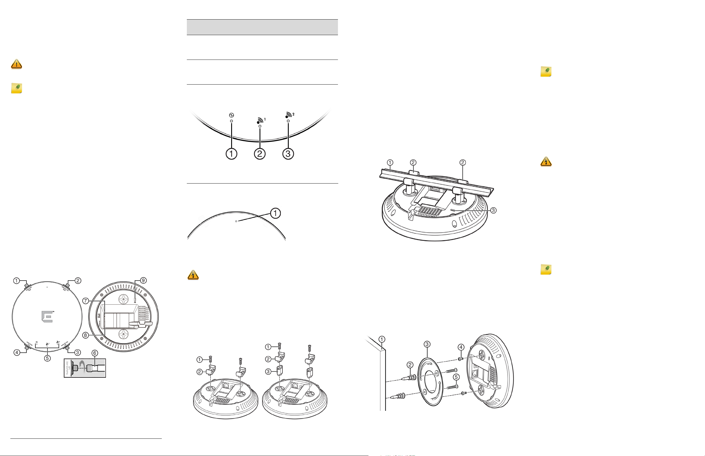
WS-AP3805 Views
Figure 1, shows the front and back of the WS-AP3805.
Figure 1 Front & Back Views of the WS-AP3805
applies to both models.
Table 1 Powering the WS-AP3805
Power
Source
Power over
Ethernet
(PoE)
External 12V
DC power
supply
(optional)
Power is provided through the RJ45 Ethernet port
(LAN port) on the top of the WS-AP3805. This is
the preferred method of powering the AP on ceiling
and high wall installations.
The WS-AP3805 can also be powered by an
external DC power supply plugged into an AC
source. Plug the supply’s input jack into the DC-In
port (see Figure 1).
Description
Figure 2 LEDs on AP Front Face
1 Power 3 Radio 2
2 Radio 1
Green LEDs mean ON. Amber LEDs mean OFF.
Figure 3 Reset Button
Mounting and Connecting the AP
Electrical Hazard: Only qualified personnel should perform
installation procedures.
A wall mount bracket is included for quick and easy
mounting of the AP to a wall. A ceiling mounting kit is also
provided for mounting on a drop ceiling. These instructions
are guidelines. For detailed information, see the Extreme
Networks IdentiFi Wireless WS-AP3805 Installation Guide
Mounting on a Drop Ceiling
1 Attach the T-rail connectors (see Figure 4, Item 2) to the
bottom cover of the AP using the provided short screws
(see Figure 4, Item 1). Two sizes of T-rail connectors are
included in the mounting hardware kit: 15/16 in (2.38 cm)
and 9/16 in (1.43 cm).
2 If extra space is required to accommodate drop ceiling
tiles, use the provided spacers and long screws (see
Figure 4, Items 1 and 3).
3 Remove the ceiling panels around the drop ceiling T-bar
rails where you intend to mount the AP.
4 Line up the connected T-rail connectors (see Figure 5,
Item 2) with an appropriately sized rail (see Figure 5,
Item 1), and press the AP onto the rail until it snaps into
place as shown in Figure 5.
5 Verify that the Ethernet cable that will connect to the AP
can reach the AP at the point where you plan to mount it.
6 With both bracket tabs over the T-bar rail lips, tap the AP
to verify it is stable and won’t fall off. Figure 5 illustrates
the AP and bracket mounted on a T-bar rail.
Figure 5 WS-AP3805 Mounted on Drop Ceiling T-bar Rail
7 Make a hole through the ceiling panel closest to the
power slot on the AP. Run the Ethernet cable through the
hole and into an RJ45 LAN port in the recessed
connector bay.
8 Replace the displaced ceiling panels.
Mounting on a Wall or Solid Flat Ceiling
Figure 6 shows the AP3805 mounted to a wall or solid
ceiling.
Figure 6 Mounting the WS-AP3805 to a Flat Wall or Solid Ceiling
1 Determine the spot on the wall where the AP is to be
mounted, preferably high up on the wall (near the ceiling
for maximum radio wave dispersion) but in reach of the
Ethernet cable and a wall power outlet if you are not able
to use Power over Ethernet.
2 Drill two holes in the wall (see Figure 6, Item 1) to match
the center of the two keyhole slots in the back of the AP
bracket (see Figure 6, Item 3).
Note: When drilling the holes for the wall anchors, the hole
diameter should be slightly smaller than the diameter of the
wall anchors provided.
3 Screw the anchors (see Figure 6, Item 2) into the holes
until they are flush with the wall, and screw the provided
mounting screws (see Figure 6 Item 5) into the anchors.
4 Screw the AP mounting screws (see Figure 6, Item 4)
into the bottom of the AP.
5 Mount the AP on the mounting bracket by aligning the
mounting screw with the slots in the bracket and rotating
the unit clockwise about 90 degrees to secure it in place.
Connecting a Power Supply to the WS-AP3805
Electrical Hazard: Do not connect the WS-AP3805 to an
external power supply if the AP is plugged into the PoE
port.
If you need to power the WS-AP3805 with an external 12V
DC power supply, you can plug the power cord into the
power connector (see Figure 1, Item 6) on the back of the
AP. There is no wall mount for the 12V DC power supply.
Refer to the Extreme Networks IdentiFi Wireless WS-
AP3805 Installation Guide for information about the power
supply.
LAN Connection
The WS-AP3805 has one LAN (Ethernet) port (see Figure 1,
Item 7). During administration and maintenance through
the LAN, the AP must still have a power connection
through either an Ethernet PoE cable or a DC power supply.
Note: LAN connectors with shrouds will not fit into the AP
port. Remove the shroud or use an optional jumper cable.
External Antennas (WS-AP3805e Only)
Install the external antennas intended for area coverage.
For information about antenna selection and installation,
refer to the Extreme Networks IdentiFi Wireless WS-
AP3805 Installation Guide.
1 Antenna Port, Radio 1 - Right
(5.0 GHz, AP3805e only)
2 Antenna Port, Radio 2 - Right
(2.4 GHz, AP3805e only)
3 Antenna Port, Radio 2 - Left
(2.4GHz, AP3805e only)
4 Antenna Port, Radio 1 - Left
(5.0 GHz, AP3805e only)
5 LEDs (see Figure 2)
Figure 4 Attaching the T-rail Connector to the AP
6 External Antenna (1 of 4),
AP3805e only
7 External Power Supply
Port
8 LAN port
9 Kensington Lock Slot
Page 2
Notice
Copyright © 2016 Extreme Networks, Inc. All Rights Reserved.
Legal Notices
Extreme Networks, Inc., on behalf of or through its wholly-owned
subsidiary, Enterasys Networks, Inc., reserves the right to make
changes in specifications and other information contained in this
document and its website without prior notice. The reader should
in all cases consult representatives of Extreme Networks to
determine whether any such changes have been made.
The hardware, firmware, software or any specifications described
or referred to in this document are subject to change without
notice.
Trademarks
Extreme Networks and the Extreme Networks logo are trademarks
or registered trademarks of Extreme Networks, Inc. in the United
States and/or other countries.
All other names (including any product names) mentioned in this
document are the property of their respective owners and may be
trademarks or registered trademarks of their respective
companies/owners.
For additional information on Extreme Networks trademarks,
please see: www.extremenetworks.com/company/legal/
trademarks/
Documentation & Support
For product support, including documentation, visit:
www.extremenetworks.com/support/
Contact
Extreme Networks, Inc.
145 Rio Robles
San Jose, CA 95134 USA
Tel: +1 408-579-2800
Toll-free: +1 888-257-3000
Regulatory and Compliance Information
Safety Guidelines
This section contains notices that are intended to protect your
personal safety and prevent damage to the equipment.
Qualified Personnel:
Electrical Hazard: Only qualified personnel should perform
installation procedures. Within the context of the safety
notes in this documentation, qualified persons are defined
as persons who are authorized to commission, ground and
label devices, systems, and circuits in accordance with
established safety practices and standards. A qualified
person understands the requirements and risks involved
with installing outdoor electrical equipment in accordance
with national codes.
RF Safety Distance
The antennas used for this transmitter must be installed to provide
a separation distance of at least 22 cm from all persons and must
not be co-located or operating in conjunction with another
antenna or transmitter.
Federal Communications Commission (FCC) Notice
This device complies with Part 15 of the FCC rules. Operation is
subject to the following two conditions: (1) this device may not
cause harmful interference, and (2) this device must accept any
interference received, including interference that may cause
undesired operation.
War ning : Changes or modifications made to this device
which are not expressly approved by the party responsible
for compliance could void the user’s authority to operate
the equipment.
Industry Canada Notice
This digital apparatus does not exceed the Class B limits for radio
noise emissions from digital apparatus set out in the Radio
Interference Regulations for the Canadian Department of
Communications.
Le présent appareil numérique n’émet pas de bruits
radioélectriques dépassant les limites applicables aux appareils
numériques de la class B prescrites dans le Règlement sur le
brouillage radioélectrique édicté par le ministère des
Communications du Canada.
Suitable for use in environmental air space in accordance with
Section 300.22.C of the National Electrical Code, and Sections 2128, 12-010(3) and 12-100 of the Canadian Electrical Code, Part 1,
C22.1.
Convient à l'espace de ventilation environnemental, conformément
à la section 300.22.C du Code national de l'électricité et aux
sections 2-128, 12-010(3) et 12-100 du Code canadien de
l'électricité, partie 1, C22.1.
European Waste Electrical and Electronic
Equipment (WEEE) Notice
In accordance with Directive 2012/19/EU of the European
Parliament on waste electrical and electronic equipment (WEEE):
1 The symbol above indicates that separate collection of electrical
and electronic equipment is required.
2 When this product has reached the end of its serviceable life, it
cannot be disposed of as unsorted municipal waste. It must be
collected and treated separately.
3 It has been determined by the European Parliament that there
are potential negative effects on the environment and human
health as a result of the presence of hazardous substances in
electrical and electronic equipment.
4 It is the users’ responsibility to utilize the available collection
system to ensure WEEE is properly treated.
For information about the available collection system, please
contact Extreme Customer Support at 353 61 705500 (Ireland).
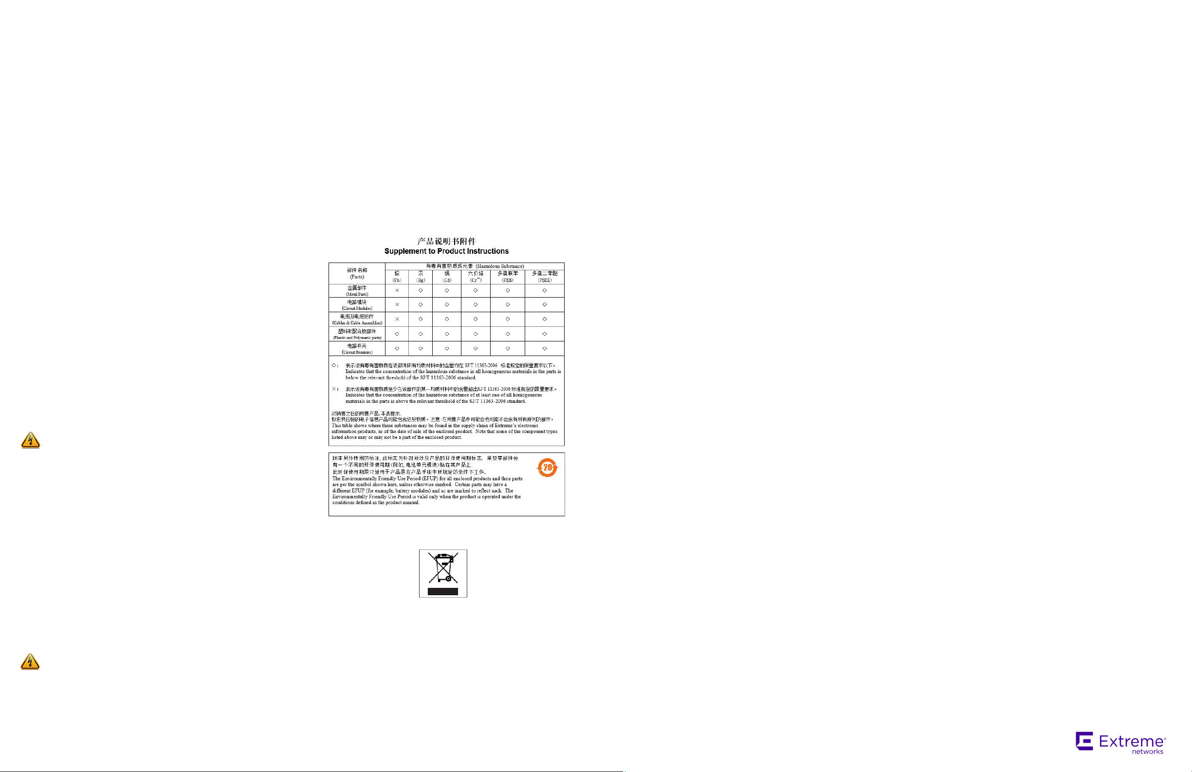
Hazardous Substances
This product complies with the requirements of Directive 2011/65/
EU of the European Parliament and of the Council of 8 June 2011
on the restriction of the use of certain hazardous substances in
electrical and electronic equipment.
Declaration of Conformity in Languages of the
European Community
English Hereby, Extreme Networks, declares that this Radio LAN
Finnish Valmistaja Extreme Networks vakuuttaa täten että Radio
Dutch Hierbij verklaart Extreme Networks dat het toestel Radio
French Par la présente Extreme Networks déclare que l'appareil
Swedish Härmed intygar Extreme Networks att denna Radio LAN
Danish Undertegnede Extreme Networks erklærer herved, at
German Hiermit erklärt Extreme Networks die Übereinstimmung des
Greek ΜΕ ΤΗΝ ΠΑΡΟΥΣΑ Extreme Networks ∆ΗΛΩΝΕΙ ΟΤΙ Radio
Icelandic Extreme Networks lysir her med yfir að thessi bunadur,
Italian Con la presente Extreme Networks dichiara che questo
Spanish Por medio de la presente Extreme Networks declara que el
Portuguese Extreme Networks declara que este Radio LAN device está
Malti Hawnhekk, Extreme Networks, jiddikjara li dan Radio LAN
device is in compliance with the essential requirements and
other relevant provisions of Directive 1999/5/EC.
LAN device tyyppinen laite on direktiivin 1999/5/EY
oleellisten vaatimusten ja sitä koskevien direktiivin muiden
ehtojen mukainen.
LAN device in overeenstemming is met de essentiële eisen
en de andere relevante bepalingen van richtlijn 1999/5/EG.
Bij deze verklaart Extreme Networks dat deze Radio LAN
device voldoet aan de essentiële eisen en aan de overige
relevante bepalingen van Richtlijn 1999/5/EC.
Radio LAN device est conforme aux exigences essentielles
et aux autres dispositions pertinentes de la directive 1999/
5/CE.
Par la présente, Extreme Networks déclare que ce Radio
LAN device est conforme aux exigences essentielles et aux
autres dispositions de la directive 1999/5/CE qui lui sont
applicables.
device står I överensstämmelse med de väsentliga
egenskapskrav och övriga relevanta bestämmelser som
framgår av direktiv 1999/5/EG.
følgende udstyr Radio LAN device overholder de
væsentlige krav og øvrige relevante krav i direktiv 1999/5/
EF.
"WLAN Wireless Controller bzw. Access Points" mit den
grundlegenden Anforderungen und den anderen relevanten
Festlegungen der Richtlinie 1999/5/EG.
LAN device ΣΥΜΜΟΡΦΩΝΕΤΑΙ ΠΡΟΣ ΤΙΣ ΟΥΣΙΩ∆ ΕΙΣ
ΑΠΑΙΤΗΣΕΙΣ ΚΑΙ ΤΙΣ ΛΟΙΠΕ Σ ΣΧΕΤΙΚΕΣ ∆ΙΑΤΑΞΕΙΣ ΤΗΣ
Ο∆ΗΓΙΑ Σ 1999/5/ΕΚ.
Radio LAN device, uppfyllir allar grunnkrofur, sem gerdar
eru i R&TTE tilskipun ESB nr 1999/5/EC.
Radio LAN device è conforme ai requisiti essenziali ed alle
altre disposizioni pertinenti stabilite dalla direttiva 1999/5/
CE.
Radio LAN device cumple con los requisitos esenciales y
cualesquiera otras disposiciones aplicables o exigibles de la
Directiva 1999/5/CE.
conforme com os requisitos essenciais e outras disposições
da Directiva 1999/5/CE.
device jikkonforma mal-htigijiet essenzjali u ma
provvedimenti ohrajn relevanti li hemm fid-Dirrettiva 1999/
5/EC.
Extreme Networks
Wireless Access Points
Quick Reference
WS-AP3805i
WS-AP3805e
9034815-02
 Loading...