

Page 1

ExtremeWireless™ AP310i/e Access Points
DRAFT
Installation Guide
9036535-00
March 2020
Page 2

Copyright © 2020 Extreme Networks, Inc. All rights reserved.
DRAFT
Legal Notice
Extreme Networks, Inc. reserves the right to make changes in specifications and other information
contained in this document and its website without prior notice. The reader should in all cases
consult representatives of Extreme Networks to determine whether any such changes have been
made.
The hardware, firmware, software or any specifications described or referred to in this document
are subject to change without notice.
Trademarks
Extreme Networks and the Extreme Networks logo are trademarks or registered trademarks of
Extreme Networks, Inc. in the United States and/or other countries.
All other names (including any product names) mentioned in this document are the property of
their respective owners and may be trademarks or registered trademarks of their respective
companies/owners.
For additional information on Extreme Networks trademarks, please see:
www.extremenetworks.com/company/legal/trademarks
Open Source Declarations
Some software files have been licensed under certain open source or third-party licenses. Enduser license agreements and open source declarations can be found at:
www.extremenetworks.com/support/policies/software-licensing
Page 3

Table of Contents
DRAFT
Preface...................................................................................................................................5
Text Conventions.......................................................................................................................................................... 5
Documentation and Training.................................................................................................................................. 7
Getting Help....................................................................................................................................................................7
Subscribe to Service Notifications..............................................................................................................7
Providing Feedback.................................................................................................................................................... 8
Product Overview................................................................................................................ 9
AP310i/e Features........................................................................................................................................................9
AP310i/e Power Source...........................................................................................................................................10
AP310i/e Power Tables............................................................................................................................................ 10
LED Indicators............................................................................................................................................................... 11
Purchase Order Information................................................................................................................................... 11
Install the Access Point......................................................................................................13
AP310i/e Box Contents............................................................................................................................................13
Access Point Installation Options and Accessory Information............................................................ 14
Install the Access Point on Drywall or Wood Wall, or to a Solid Flat Ceiling................................15
Install the Access Point Using the Main Mounting Bracket...........................................................16
Install the Access Point Using the WALL04 Bracket........................................................................19
Install the Access Point Using the Main Mounting Bracket and Easy-Attach
Adapter................................................................................................................................................................... 19
Install the Access Point Directly on a Wall.............................................................................................21
Install the Access Point on a Suspended Ceiling or a Drop Ceiling with a Flat T-bar............... 21
Install the Access Point on a Flat T-bar Using Main Mounting Bracket..................................22
Install the Access Point on a Flat T-bar Using Main Mounting Bracket and
KT-135628-01 Adapter.................................................................................................................................... 24
Install the Access Point on a Flat T-bar Using the DCFLUSH bracket.................................... 25
Install the Access Point on a Flat T-bar Using the DCMTR01 Bracket.................................... 27
Install the Access Point on a Junction Box or Gang Box.......................................................................28
Install the Access Point on a Beam...................................................................................................................28
Antenna Configuration for External Antenna Model Access Point............................ 32
Antenna socket radio mapping information.................................................................................................32
Access Points Specifications........................................................................................... 34
Physical specifications............................................................................................................................................ 34
Environmental specifications...............................................................................................................................34
Regulatory Information.....................................................................................................35
Safety Guidelines....................................................................................................................................................... 35
MPE Statement for Mobile Devices...................................................................................................................35
Federal Communications Commission (FCC) Notice..............................................................................36
Industry Canada Notice..........................................................................................................................................36
ExtremeWireless™ AP310i/e Access Points iii
Page 4

Table of Contents
DRAFT
Detachable Antenna Usage..................................................................................................................................37
Detachable Antenna Usage......................................................................................................................... 37
Australia Notice.......................................................................................................................................................... 38
AU co-location MPE Statement.................................................................................................................38
Brazil Anatel Statement..........................................................................................................................................38
Hazardous Substances............................................................................................................................................38
Supplement to Product Instructions................................................................................................................39
NCC Statement...........................................................................................................................................................39
CE Information............................................................................................................................................................39
Selling Countries:...............................................................................................................................................39
All Operational Modes....................................................................................................................................40
European Waste Electrical and Electronic Equipment (WEEE) Notice.........................................40
Declaration of Conformity in Languages of the European Community..........................................41
Index....................................................................................................................................44
iv ExtremeWireless™ AP310i/e Access Points
Page 5
Preface
DRAFT
This section describes the text conventions used in this document, where you can find additional
information, and how you can provide feedback to us.
Text Conventions
Unless otherwise noted, information in this document applies to all supported environments for the
products in question. Exceptions, like command keywords associated with a specific software version,
are identified in the text.
When a feature, function, or operation pertains to a specific hardware product, the product name is
used. When features, functions, and operations are the same across an entire product family, such as
ExtremeSwitching switches or SLX routers, the product is referred to as the switch or the router.
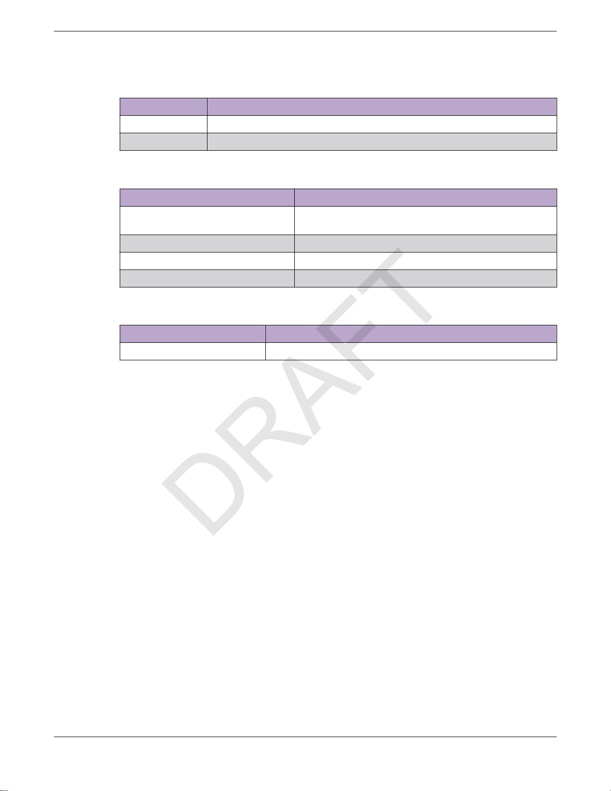
Table 1: Notes and warnings
Icon Notice type Alerts you to...
Tip Helpful tips and notices for using the product.
Note Useful information or instructions.
Important Important features or instructions.
ExtremeWireless™ AP310i/e Access Points 5
Page 6
Text Conventions Preface
DRAFT
Table 1: Notes and warnings (continued)
Icon Notice type Alerts you to...
Caution Risk of personal injury, system damage, or loss of data.
Warning Risk of severe personal injury.
Table 2: Text
Convention Description
screen displays
The words enter and type When you see the word enter in this guide, you must type something,
This typeface indicates command syntax, or represents information as
it appear
and then press the Return or Enter key. Do not press the Return or
Enter key when an instruction simply says type.
s on the screen.
Key names Key names are written in boldface, for example Ctrl or Esc. If you must
press two or more keys simultaneously, the key names are linked with a
plus sign (+). Example: Press Ctrl+Alt+Del
Words in italicized type Italics emphasize a point or denote new terms at the place where they
are defined in the text. Italics are also used when referring to
publication titles.
This symbol
Table 3: Command syntax
Convention Description
bold t
ext Identifies command names, keywords, and command options.
italic text Identifies a variable.
[ ]
{ x | y | z }
x | y
< >
Syntax components displayed within square brackets are optional.
Default responses to system prompts are enclosed in square brackets.
A choice of required parameters is enclosed in curly brackets separated
by vertical bars. You must select one of the options.
A vertical bar separates mutually exclusive elements.
Nonprinting characters, such as passwords, are enclosed in angle
brackets.
identifies new content. In a PDF, this is searchable text.
... Repeat the previous element, for example, member[member...].
\ Indicates a “soft” line break in command examples. If a backslash
separ
ates two lines of a command input, enter the entire command at
the prompt without the backslash.
6 ExtremeWireless™ AP310i/e Access Points
Page 7

Preface Documentation and Training
DRAFT
Documentation and Training
Find Extreme Networks product information at the following locations:
Current Product Documentation
Release Notes
Hardware/software compatibility matrices for Campus and Edge products
Supported transceivers and cables for Data Center products
Other resources, like white papers, data sheets, and case studies
Extreme Networks oers product training courses, both online and in person, as well as specialized
certifications. For details, visit www.extremenetworks.com/education/.
Getting Help
If you require assistance, contact Extreme Networks using one of the following methods:
Extreme Portal
Search the GTAC (Global Technical Assistance Center) knowledge base; manage support cases and
service contracts; download software; and obtain product licensing, training, and certifications.
The Hub
A forum for Extreme Networks customers to connect with one another, answer questions, and share
ideas and feedback. This community is monitored by Extreme Networks employees, but is not
intended to replace specific guidance from GTAC.
Call GTAC
For immediate support: (800) 998 2408 (toll-free in U.S. and Canada) or 1 (408) 579 2826. For the
support phone number in your country, visit: www.extremenetworks.com/support/contact
Before contacting Extreme Networks for technical support, have the following information ready:
• Your Extreme Networks service contract number, or serial numbers for all involved Extreme
Networks products
• A description of the failure
• A description of any actions already taken to resolve the problem
• A description of your network environment (such as layout, cable type, other relevant environmental
information)
• Network load at the time of trouble (if known)
• The device history (for example, if you have returned the device before, or if this is a recurring
problem)
• Any related RMA (Return Material Authorization) numbers
Subscribe to Service Notifications
You can subscribe to email notifications for product and software release announcements, Vulnerability
Notices, and Service Notifications.
1. Go to www.extremenetworks.com/support/service-notification-form.
2. Complete the form (all fields are required).
ExtremeWireless™ AP310i/e Access Points 7
Page 8

Providing Feedback Preface
DRAFT
3. Select the products for which you would like to receive notifications.
Note
You can modify your product selections or unsubscribe at any time.
4. Select Submit.
Providing Feedback
The Information Development team at Extreme Networks has made every eort to ensure the accuracy
and completeness of this document. We are always striving to improve our documentation and help
you work better, so we want to hear from you. We welcome all feedback, but we especially want to
know about:
• Content errors, or confusing or conflicting information.
• Improvements that would help you find relevant information in the document.
• Broken links or usability issues.
If you would like to provide feedback, you can do so in three ways:
• In a web browser, select the feedback icon and complete the online feedback form.
• Access the feedback form at https://www.extremenetworks.com/documentation-feedback/.
• Email us at documentation@extremenetworks.com.
Provide the publication title, part number, and as much detail as possible, including the topic heading
and page number if applicable, as well as your suggestions for improvement.
8 ExtremeWireless™ AP310i/e Access Points
Page 9

Product Overview
DRAFT
AP310i/e Features on page 9
AP310i/e Power Source on page 10
AP310i/e Power Tables on page 10
LED Indicators on page 11
Purchase Order Information on page 11
The AP310i/e access points are indoor model 802.11ax access points. The “i” in AP310i indicates that the
access point comes with internal antennas, and the “e” indicates that it comes with external antenna
connectors. The access points feature built-in dual-band radios, two band-locked radios, four WiFi
internal or external antennas, and one Bluetooth Low Energy (BLE) antenna.
The AP310i/e is mounted on a flat surface such as a wall, a solid flat ceiling, or to a junction or gang box,
and can be installed on a suspended or drop ceiling.
Note
The AP310i/e requires a minimum base firmware of WiNG 7.3.1.
In this document, the access points are addressed as AP310i/e when the product features and
installation procedures are the same for both access points.
AP310i/e Features
The AP310i/e access points have the following features:
• Radios:
◦ Two 802.11ax radios (one 2×2 2.4 GHz and 5 GHz radio, and one 2×2 5 GHz radio)
◦ One IoT radio (2.4 GHz)
• Console port: RJ45
• Two, one gigabyte Ethernet ports
◦ GE1 port
◦ GE2 port
• LED indicators: Six
All LED indicators will be powered on during reset.
• One reset button
• One Kensington lock
ExtremeWireless™ AP310i/e Access Points 9
Page 10
AP310i/e Power Source Product Overview
DRAFT
• One safety hanger provision
• One USB 2.0 type A connector
• Power: PoE at 802.3at and 802.3bt (see AP310i/e Power Source for details)
• Antennas:
◦ AP310i: Four Wi-Fi internal antennas and one BLE internal antenna
◦ AP310e: Four RP-SMA external antenna ports and one BLE RP-SMA antenna
• Temperature:
◦ AP310i: 0°C to +50°C (32°F to +122°F)
◦ AP310e: -20°C to +55°C (-4°F to +131°F)
• Enclosure: Plastic
AP310i/e Power Source
Power source Description
Power over Ethernet (PoE) Power is provided through the 1G Ethernet port of
AP310i/e, c
and 802.3bt to provide full functionality. For
reduced functionality, use 802.3af.
ompliant to be powered with 802.3at
PoE out PoE power source is available on GE2 port when
External 12V DC power supply (optional; ordering
part #37219- PWR 12VDC, 3A, 2.5mm x 5.5mm
connector)
Note
P
oE is disabled when external power supply is used.
AP310i/e Power Tables
Table 4: AP310i power table
AP310i 802.3af 802.3at and DC
Radio 0 (sensor) 2.4G – 2×2 (20dBm)
Radio 0 (2.4G) 2×2 (20dBm) 2×2 (20dBm)
Radio 0 (5G–L) 2×2 (18dBm) 2×2 (18dBm)
Radio 1 (5G–F) 2×2 (20dBm) 2×2 (20dBm)
Radio 1 (5G–H) 2×2 (18dBm) 2×2 (18dBm)
5G – 2×2 (19dBm)
the input power is at 802.3at.
Power is provided through an external DC power
supply plugged into an AC source.
2.4G – 2×2 (20dBm)
5G – 2×2 (19dBm)
BLE On On
USB O On
PSE O On
10 ExtremeWireless™ AP310i/e Access Points
Page 11
Product Overview LED Indicators
DRAFT
Table 5: AP310e power table
AP310e 802.3af 802.3at and DC
Radio 0 (sensor) 2.4G – 2×2 (19dBm)
Radio 0 (2.4G) 2×2 (19dBm) 2×2 (19dBm)
Radio 0 (5G–L) 2×2 (16dBm) 2×2 (16dBm)
Radio 1 (5G–F) 2×2 (18dBm) 2×2 (18dBm)
Radio 1 (5G–H) 2×2 (16dBm) 2×2 (16dBm)
BLE On On
USB O On
PSE O On
LED Indicators
The LED indicators are located on the front face of the access point but are not visibly marked.
Table 6: AP310i/e LED indicators
LED indicator LED color Description
Status Green Normal operational status
GE1 Ethernet Amber 100 Mbps
2.4G – 2×2 (19dBm)
5G – 2×2 (17dBm)
Amber Non-operational status
5G – 2×2 (17dBm)
GE2 Ethernet Amber 100 Mbps
Radio 1 Green 2.4G activity
Radio 2 Amber 5G activity
IoT (BLE) Blue Indicates BLE is enabled
Purchase Order Information
Table 7: Bracket purchase order information
Part number Description
37201 Main mounting bracket for indoor access points (included in the access point
box), along with the 50 mm M3 security screw pack for main mounting bracket
30518 WS-MBI-DCMTR01 bracket
Green 1000 Mbps
Green 1000 Mbps
Amber 5G activity
ExtremeWireless™ AP310i/e Access Points 11
Page 12
Purchase Order Information Product Overview
DRAFT
Table 7: Bracket purchase order information (continued)
Part number Description
30516 WS-MBI-WALL04 bracket
37211 WS-MBI-DCFLUSH bracket
Table 8: Bracket accessory purchase order information
Part number Description
KT-135628-01 Universal mounting kit for wireless LAN (WLAN) access
points
37210 Flat metal easy-attach adapter for main mounting bracket
BRKT-000147A-01 Beam clip accessory
30525; WS-CAB-RJ45-FLT01 RJ45 flat cable accessory for ceiling mount brackets
Table 9: Power supply purchase order information
Part number Description
37215 PWR 12V DC, 3A, 2.5 mm X 5.5 mm connector
12 ExtremeWireless™ AP310i/e Access Points
Page 13

Install the Access Point
DRAFT
AP310i/e Box Contents on page 13
Access Point Installation Options and Accessory Information on page 14
Install the Access Point on Drywall or Wood Wall, or to a Solid Flat Ceiling
on page 15
Install the Access Point on a Suspended Ceiling or a Drop Ceiling with a Flat Tbar on page 21
Install the Access Point on a Junction Box or Gang Box on page 28
Install the Access Point on a Beam on page 28
About This Task
The access point is installed on flat surfaces such as drywall or wood wall, solid flat ceiling, suspended
or drop ceiling with T-bar, to beams, or to a junction or gang box. Optional adapters and brackets are
available for mounting the access point to non-flat ceiling tiles and T-bars.
See purchase order information for details on access points and optional brackets part numbers.
Before installing the access point:
Procedure
1. Verify the box contents.
2. Visually inspect the access point, the bracket, and any other optional accessories you have ordered
for physical damage.
If there is any damage, contact Extreme Networks Support.
3. Read and review the safety guidelines.
AP310i/e Box Contents
When you purchase the AP310i or AP310e access point, ensure that the following items are available in
the box:
• An AP310i/e Quick Reference
• One access point (AP310i or AP310e)
• A stainless-steel mounting bracket for 802.11ax indoor access point
ExtremeWireless™ AP310i/e Access Points 13
Page 14
Access Point Installation Options and Accessory
DRAFT
Information Install the Access Point
• Two Phillips pan head wood screws
• Two screw-in anchors
Note
All optional brackets and accessories are sold separately.
Access Point Installation Options and Accessory Information
The access point comes with the main mounting bracket (#37201; mounting bracket for 802.11ax indoor
access points). There are various optional brackets, bracket adapters, and accessories that can be
purchased separately.
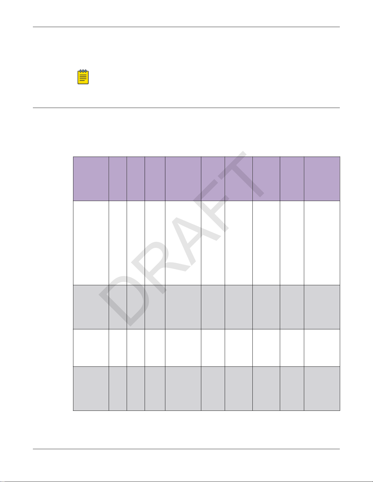
Table 10: Bracket and accessory usage for various installation options
Mounting
bracket or
accessory
37201; main
mounting
bracket
KT-135628-0
1 accessory;
used with
main
mounting
bracket
30518 WSMBIDCMTR01
bracket
Wall
Solid
Ceilin
instal
flat
g
l
ceilin
install
g
(T-
instal
bar)
l
Yes Yes Yes Yes, by
No No Yes Yes No No Yes 15/16 in. Wall mount
No No Yes Yes No No Yes 9/16 in.,
Ceiling
install
(protruded
T-bar)
adding the
optional Tbar adapter
to the main
mounting
bracket
Junctio
n box
install
No Yes, by
Beam
install
adding
the
beam
clip
accessor
y to the
main
mountin
g bracket
Ceiling
tile
protrusio
n
No 15/16 in. This bracket
T-bar
widths
3/2 in.,
15/16 in.
Notes
is shipped
with the
access
point.
Installation
methods:
Wall mount
or flush
ceiling
mount with
single width.
or
protruded
ceiling
mount with
single width.
Protruded
ceiling
mount with
varying
widths.
30516 WSMBIWALL04
bracket
14 ExtremeWireless™ AP310i/e Access Points
Yes No No No Yes No No No Wall mount
with single
width.
Junction
box
installation.
Page 15

Install the Access Point
DRAFT
Table 10: Bracket and accessory usage for various installation options (continued)
Install the Access Point on Drywall or Wood Wall, or to a
Solid Fla
t Ceiling
Mounting
bracket or
accessory
37210 flat
metal easyattach
adapter;
used with
main
mounting
bracket
37211 WSMBIDCFLUSH
bracket
BRKT-0001
47A-01;
beam clip
accessory
Wall
Solid
Ceilin
instal
flat
g
l
ceilin
install
g
(T-
instal
bar)
l
Yes Yes No No No No No N/A Wall mount,
No No Yes Yes No No Yes 9/16 in.,
No No No No No Yes No N/A The beam
Ceiling
install
(protruded
T-bar)
Junctio
n box
install
Beam
install
Ceiling
tile
protrusio
n
T-bar
widths
3/2 in.,
15/16 in.
Notes
ceiling
mount, or
install on
any solid
surface.
Protruded
ceiling
mount with
varying
widths.
clip is
attached to
the main
mounting
bracket.
30525 WSCAB-RJ45FLT01
accessory
No Yes Yes No No No No N/A This
accessory
can be used
only with
ceiling
mount
brackets
listed in this
table.
Install the Access Point on Drywall or Wood Wall, or to a Solid Flat Ceiling
About This Task
The access point is installed on a drywall or wood wall or to a solid flat ceiling using:
• #37201, stainless-steel main mounting bracket that ships with the unit
• #30516, WS-MBI-WALL04 bracket, two Phillips pan-head screws, and screw-in anchors
Note
T
he WALL04 bracket and screw-in anchors are used only for drywall or wood wall
mounting.
ExtremeWireless™ AP310i/e Access Points 15
Page 16

Install the Access Point Using the Main Mounting
DRAFT
acket Install the Access Point
Br
• #37201, stainless-steel main mounting bracket with #37210, flat metal easy-attach adapter
• Phillips pan head screws
Tip
he best practice is to install the access point using the mounting brackets.
T
Install the Access Point Using the Main Mounting Bracket
About T
The main mounting bracket is a stainless-steel bracket that ships with the access point. It is used during
drywall or wood wall installation, or solid flat ceiling installation.
Procedure
1.
his Task
Tip
he best practice is to use the main mounting bracket for all wall installations.
T
Using the mounting bracket as a template, mark and drill two hole centers on the wall.
Note
T
he bracket feet must be pointing up.
16 ExtremeWireless™ AP310i/e Access Points
Page 17

Install the Access Point
DRAFT
Install the Access Point Using the Main Mounting
Br
acket
Figure 1: Main mounting bracket
Callout Description
1 Main mounting bracket mounting holes
2 Main mounting bracket feet
2. Insert the Phillips pan head screws into the main mounting bracket holes and attach the bracket to
all.
the w
Use screw-in anchors, if needed.
3. Connect the Ethernet cable RJ45 connector into the GE1 port.
4. Place the access point onto the bracket feet and slide it down to lock it in place.
Install a Security Torx Locking Screw
About This Task
The security torx locking screw is used to prevent the access point from being removed from the main
mounting bracket (#37201). There are two security lock screw holes on the rear of the access point.
ExtremeWireless™ AP310i/e Access Points 17
Page 18

Install the Access Point Using the Main Mounting
DRAFT
Bracket Install the Access Point
Follow this procedure to install the security torx locking screw using one of the security lock holes on
the access point.
Note
Perform this task after the access point is attached to the main mounting bracket on a drywall
or wood wall.
Procedure
1. Line up the security torx locking screw using the rear guides on the access point.
2. Using a T8 bit screwdriver, tighten the security torx locking screw.
3. Turn the locking screw into the security screw hole until the security torx locking screw passes
through to the other side and touches the screw stop feature.
Figure 2: Security torx locking screw stop feature
Callout Description
1 Security torx locking screw stop feature
Note
You cannot remove the access point from the main mounting bracket until the security
torx locking screw is removed.
18 ExtremeWireless™ AP310i/e Access Points
Page 19

Install the Access Point Install the Access Point Using the WALL04 Bracket
DRAFT
Install the Access Point Using the WALL04 Bracket
About This Task
The optional WALL04 (#30516) bracket is used for wall installations, and ships with two Phillips pan
head screws and two screw-in anchors. You must purchase the bracket separately.
Note
The locking tab on the WS-MBI-WALL04 bracket must be on the top side during installation.
Procedure
1. Using the WALL04 bracket as a template, mark and drill two holes on a wall.
Tip
The best practice is to use the "A" and "B" hole templates on the WALL04 bracket to mark
the attachment holes.
Note
When using the "A" or "B" hole template, if the holes are not near the corners of the
bracket, you can break o the corner to minimize the amount of bracket that is visible
behind the access point.
2. Attach the WS-MBI-WALL04 bracket on a wall using two Phillips pan head screws.
Tip
The best practice is to install the screw-in anchors before attaching the pan head screws
during drywall installations.
3. Connect the GE1 cable to the access point.
4. Insert the access point into the WALL04 bracket keyhole posts and slide it into place.
5. Lock the access point at approximately 1/4th-inch from the bracket.
Install the Access Point Using the Main Mounting Bracket and Easy-Attach Adapter
About This Task
Use the flat metal easy-attach adapter (#37210) in combination with the main mounting bracket
(#37201) when you do not want to use the screw holes on the main mounting bracket. The easy-attach
adapter extends past the access point housing, thereby making it convenient to easily attach and
remove the access point from a flat surface.
ExtremeWireless™ AP310i/e Access Points 19
Page 20

Install the Access Point Using the Main Mounting
DRAFT
Br
acket and Easy-Attach Adapter Install the Access Point
Procedure
1. Keep the adapter to the center of the main mounting bracket, push and rotate it.
Figure 3: Flat metal easy-attach adapter being attached to the main mounting
acket
br
2. Using the attachment holes on the easy-attach adapter, mark and drill two hole centers on a wall or
a solid flat ceiling.
3. Attach the easy-attach adapter to the wall using two Phillips pan-head screws.
Use screw-in anchors, if needed.
4. Connect the Ethernet cable RJ45 connector into the GE1 port.
20 ExtremeWireless™ AP310i/e Access Points
Page 21

Install the Access Point Install the Access Point Directly on a Wall
DRAFT
5. Place the access point onto the bracket feet and slide it down to lock it in place.
Note
The bracket feet must be pointing up.
Install the Access Point Directly on a Wall
About This Task
If you do not want to use the main mounting bracket that ships with the access point, you can install the
access point directly on a wall using two Phillips pan head screws.
Tip
he best practice is to use the main mounting bracket for wall installations.
T
Procedure
Measure and drill two holes 4.100 in. (104 mm) apart from each other on the wall.
1.
2. Insert the Phillips pan head screws into the mounting holes on the wall.
Use screw-in anchors, if needed.
Note
L
eave 1/8 in. gap between the screw head and the wall.
3. Connect the Ethernet cable RJ45 into the GE1 port.
4. Align the access point against the screw heads and slide it down.
5. Ensure that the access point is secured in place.
If the access point is loose, unmount it and decrease the distance between the two screw heads.
Then, remount the access point.
Install the Access Point on a Suspended Ceiling or a Drop Ceiling with a Flat T-bar
About This Task
F
or suspended ceiling or drop ceiling installation, the main mounting bracket is used directly on the Tbar. If there is a ceiling tile protrusion, the optional T-bar adapter is attached to the main mounting
bracket prior to T-bar installation.
The access point is mounted to a suspended or a drop ceiling using:
• #37201, stainless-steel main mounting bracket to a flat T-bar
• #37201, stainless-steel main mounting bracket with KT-135628-01 adapter to a flat T-bar
• #37211, WS-MBI-DCFLUSH bracket to a flat T-bar
• #30518, WS-MBI-DCMTR01 bracket to a T-bar
ExtremeWireless™ AP310i/e Access Points 21
Page 22

Install the Access Point on a Flat T-bar Using Main
DRAFT
Mounting Bracket Install the Access Point
Install the Access Point on a Flat T-bar Using Main Mounting Bracket
Before You Begin
Ensure that the T-bar meets the following conditions before installing the main mounting bracket on a
flat T-bar:
• T-bar width must be 15/16 in. (24 mm).
• T-bar bottom must be flat, all the way across the ceiling.
• T-bar must be structurally sound.
• T-bar maximum base thickness must not exceed 0.055 in. (1.4 mm).
• Ceiling tile over the T-bar must be flat, all the way across.
About This Task
The main mounting bracket is used on a T-bar when the ceiling model is a suspended or drop ceiling
and when there is a T-bar on the ceiling.
Procedure
1. Remove the ceiling tiles.
22 ExtremeWireless™ AP310i/e Access Points
Page 23

Install the Access Point
DRAFT
2. Push and rotate the main mounting bracket on the T-bar in such a way that the center angled
locking tabs of the main bracket gets attached to the T-bar.
Install the Access Point on a Flat T-bar Using Main
Mounting Br
acket
Figure 4: Install the main mounting bracket on a T-bar
3.
Place the access point on the bracket feet and slide it down to lock it in place.
Hold the access point and rock it back and forth to ensure that it is securely mounted.
4. Replace the ceiling tiles.
5. Attach the RJ45 connector to the GE1 port.
ExtremeWireless™ AP310i/e Access Points 23
Page 24

Install the Access Point on a Flat T-bar Using Main
DRAFT
Mounting Bracket and KT-135628-01 Adapter Install the Access Point
Install the Access Point on a Flat T-bar Using Main Mounting Bracket and KT-135628-01 Adapter
Before You Begin
Ensure that the T-bar meets the following conditions before installing the main mounting bracket with
the KT-135628-01 adapter on a T-bar:
• T-bar width can be either 9/16 in. (15 mm) or 15/16 in. (24 mm).
• T-bar bottom must be flat all the way across.
• T-bar must be structurally sound.
• T-bar maximum base thickness must not exceed 0.055 in. (1.4 mm).
Due to manufacturing variation, some adapters can accommodate up to 0.060 in. (1.5 mm).
• Ceiling tile may protrude up to 0.35 in. (8.89 mm) below the T-bar.
About This Task
If the ceiling tile is not flat and has a protrusion, use the main mounting bracket with the KT-135628-01
adapter. Attach the adapter to the main mounting bracket before attaching the bracket to a T-bar.
Procedure
1. Attach the T-bar adapter to the main mounting bracket by lining up the small bends on the adapter
with the long raised parts on the main bracket.
2. Pull up the KT-135628-01 adapter locking pin, and twist.
Ensure that the locking pin goes into the locking pin hole on the main bracket and locks in place.
24 ExtremeWireless™ AP310i/e Access Points
Page 25

Install the Access Point
DRAFT
Install the Access Point on a Flat T-bar Using the
DCFLUSH bracket
Figure 5: Attach the KT-135628-01 adapter on the main mounting bracket
Callout Description
A KT-135628-01 adapter
B KT-135628-01 T-bar holder
C KT-135628-01 adapter locking pin
3. Slide the KT-135628-01 T-bar holder onto the T-bar and replace the tiles to hold the adapter onto the
-bar.
T
4. Hold and rock the access point back and forth to ensure that it is securely mounted.
5. Attach the RJ45 connector to the GE1 port.
Install the Access Point on a Flat T-bar Using the DCFLUSH bracket
Before You Begin
Ensure that the T-bar meets the following conditions before installing the DCFLUSH bracket on it:
• T-bar width must be 9/16 in. (15mm), 15/16 in. (24mm), or 1.5 in. (38 mm).
• T-bar bottom must be flat all the way across.
• T
-bar must be structurally sound.
• T-bar maximum base thickness must not exceed 0.080 in. (2 mm).
• Ceiling tile must be flat all the way across.
• Maximum ceiling tile protrusion allowed is 0.015 in. (0.380 mm).
ExtremeWireless™ AP310i/e Access Points 25
Page 26

Install the Access Point on a Flat T-bar Using the
DRAFT
DCFL
USH bracket Install the Access Point
About This Task
The WS-MBI-DCFLUSH (#37211) bracket is used on a flat T-bar when you do not want to use the main
mounting bracket on it.
Procedure
1. Remove the ceiling panels around the T-bar.
2. Open the movable sliding part of the DCFLUSH bracket to give the stationary and slider T-bar more
space.
Figure 6: DCFLUSH bracket parts and T-bar
Callout Description
1 T-bar
2 Movable sliding part of the DCFLUSH bracket
3. Hook the stationary end of the bracket onto the T-bar.
Tilt the T-bar up slightly in such a way that you are holding the stationary and movable parts of the
4.
bracket.
5. Squeeze the bracket parts together until you hear the T-bar locking tab click into place.
6. Slide the bracket base into the rear groove of the access point.
7. Hold and rock the access point back and forth to ensure that it is securely mounted.
8. Attach the RJ45 connector to the GE1 port.
9. Replace the ceiling tiles.
26 ExtremeWireless™ AP310i/e Access Points
Page 27

Install the Access Point on a Flat T-bar Using the
DRAFT
Install the Access Point
Install the Access Point on a Flat T-bar Using the DCMTR01 Bracket
Before You Begin
Ensure that the T-bar meets the following conditions before installing the DCMTR01 bracket on it:
• T-bar width must be 9/16 in. (15 mm), 15/16 in. (24 mm), or 1.5 in. (38 mm).
• T-bar must be structurally sound.
• T-bar maximum base thickness cannot exceed 0.118 in. (3 mm).
• T-bar maximum protrusion must be 0.625 in. (15.800 mm).
• Maximum protrusion of the ceiling tile cannot exceed 0.625 in. (15.800 mm).
About This Task
The optional WS-MBI-DCMTR01 (#30518) bracket is used for T-bar installations when the main
mounting bracket is not used.
Procedure
1. Remove the ceiling panels around the T-bar.
2. Open the movable sliding part of the DCMTR01 bracket to give the stationary end of the bracket and
the slider T-bar more space.
DCMTR01 Bracket
Figure 7: DCMTR01 bracket parts and T-bar
Callout Description
1 T-bar
2 Movable sliding part of the DCMTR01 bracket
3 Stationary part of the DCMTR01 bracket
3. Hook the stationary end of the bracket onto the T-bar.
4. Tilt the T-bar up slightly in such a way that you are holding the stationary and movable parts of the
bracket.
ExtremeWireless™ AP310i/e Access Points 27
Page 28

Install the Access Point on a Junction Box or Gang Box Install the Access Point
DRAFT
5. Squeeze the bracket parts together until you hear the T-bar locking tab click into place.
6. Slide the bracket base into the rear groove of the access point.
7. Hold and rock the access point back and forth to ensure that it is securely mounted.
8. Attach the RJ45 connector to the GE1 port.
9. Replace the ceiling tile.
Install the Access Point on a Junction Box or Gang Box
About This Task
The main mounting bracket or the optional WALL04 (#30516) bracket is used for installing the access
point on a junction box or gang box. The main mounting bracket is used only when the mounting holes
on the bracket and the box align.
Note
The box models are limited to the USA box models when using the main mounting bracket for
installation.
Procedure
1. Remove the screws holding the box coverplate.
2. Remove the LAN cable from the coverplate.
3. Place the WALL04 bracket, with the locking tab pointing up, against the mounting holes on the box.
Note
The bracket must be square to the rest of the room walls, and the two holes that are being
used must be on the opposite sides of large center hole on the WALL04 bracket.
If the WALL04 bracket holes do not align with the mounting holes on the junction or gang box, cut
and enlarge the holes on the WALL04 bracket.
4. Attach the WALL04 bracket to the junction or gang box using the screws removed from the junction
or gang box.
Caution
Over tightening the screws will cause the WALL04 bracket to bend. If the bracket bends,
you will not be able to align and slide the access point onto the keyhole posts.
5. Connect the GE1 cable to the access point.
6. Slide the access point on the keyhole slots of the WALL04 bracket until you hear it lock in place.
Install the Access Point on a Beam
Before You Begin
Verify that the:
• Beam attachment area is at least 0.5 in. (12.7 mm) wide and as long as the largest dimension of the
access point.
• Beam mounting surface is less than 0.650 in. (16.5 mm) thick.
28 ExtremeWireless™ AP310i/e Access Points
Page 29

Install the Access Point Install the Access Point on a Beam
DRAFT
About This Task
If you do not want to install the access point on a solid flat surface, you can attach it to a beam using
the beam clip accessory (BRKT-000147A-01). The access point can be attached to a beam only if the
beam is flat, and can support the access point in all environmental conditions.
Figure 8: Beam clip accessory
ExtremeWireless™ AP310i/e Access Points 29
Page 30

Install the Access Point on a Beam Install the Access Point
DRAFT
Procedure
1. Attach the beam clip to the main mounting bracket.
Slide the beam clip accessory into the rear hinges on either side of the main mounting bracket and
slightly twist it until the clip locks into place.
Figure 9: Beam clip accessory attached to the main mounting bracket
Place the access point onto the main mounting bracket feet and slide it down to lock it in place.
2.
3. Place the beam clip accessory on a beam.
Note
e that you leave enough space between the beam clip accessory screw and the
Ensur
clamp. This helps to tighten the beam clip accessory screw easily.
30 ExtremeWireless™ AP310i/e Access Points
Page 31

Install the Access Point Install the Access Point on a Beam
DRAFT
4. Tighten the beam clip accessory screw to secure the access point in place.
Figure 10: Beam clip accessory attached to a beam
Connect the Ethernet cable RJ45 into the GE1 port.
5.
ExtremeWireless™ AP310i/e Access Points 31
Page 32

Antenna Configuration for External
DRAFT
Antenna Model Access Point
Figure 11: AP310e external antennas
32 ExtremeWireless™ AP310i/e Access Points
Page 33

Antenna Configuration for External Antenna Model
DRAFT
Access Point Antenna socket radio mapping information
Antenna socket radio mapping information
• Radio 1 (R1) - antennas 1 and 2
• Radio 2 (R2) - antennas 3 and 4
• IoT radio - BLE antenna
ExtremeWireless™ AP310i/e Access Points 33
Page 34

Access Points Specifications
DRAFT
Physical specifications
Item Specification
Dimensions 6.4 in. × 6.4 in. × 1.7 in. (165 mm × 165 mm × 45
mm)
Weight 1.5 lbs. (0.70 kg)
Housing Plastic
LED Six
Radios Two 802.11ax radios
Console port RJ45
Environmental specifications
Item Specification
Operating temperature AP310i: 0°C to +50°C (32°F to +122°F)
AP310e: -20°C to +55°C (-4°F to +131°F)
Storage temperature -40°C to +70°C (-40°F to +158°F)
Humidity 0% to 95% (non-condensing)
Operating altitude 6000 ft.
34 ExtremeWireless™ AP310i/e Access Points
Page 35

Regulatory Information
DRAFT
Safety Guidelines on page 35
MPE Statement for Mobile Devices on page 35
Federal Communications Commission (FCC) Notice on page 36
Industry Canada Notice on page 36
Detachable Antenna Usage on page 37
Australia Notice on page 38
Brazil Anatel Statement on page 38
Hazardous Substances on page 38
Supplement to Product Instructions on page 39
NCC Statement on page 39
CE Information on page 39
European Waste Electrical and Electronic Equipment (WEEE) Notice
on page 40
Declaration of Conformity in Languages of the European Community
on page 41
Safety Guidelines
The following safety guidelines are intended to protect your personal safety and prevent damage to the
equipment.
Important
Only qualified personnel should perform installation procedures. Within the context of the
safety notes in this documentation, qualified persons are defined as persons who are
authorized to commission, ground, and label devices, systems, and circuits in accordance with
established safety practices and standards. A qualified person understands the requirements
and risks involved with installing outdoor electrical equipment in accordance with national
codes.
MPE Statement for Mobile Devices
This equipment complies with EU radiation exposure limits set forth for an uncontrolled environment.
This equipment should be installed and operated with a minimum distance of 26 cm between the
radiator and your body.
ExtremeWireless™ AP310i/e Access Points 35
Page 36

Federal Communications Commission (FCC) Notice Regulatory Information
DRAFT
Federal Communications Commission (FCC) Notice
This equipment has been tested and found to comply with the limits for a Class B digital device,
pursuant to Part 15 of the FCC Rules. These limits are designed to provide reasonable protection against
harmful interference in a residential installation. This equipment generates, uses, and can radiate radio
frequency energy and, if not installed and used in accordance with the instructions, may cause harmful
interference to radio communications. However, there is no guarantee that interference will not occur in
a particular installation. If this equipment does cause harmful interference to radio or television
reception, which can be determined by turning the equipment o and on, the user is encouraged to try
to correct the interference by one of the following measures:
• Reorient or relocate the receiving antenna.
• Increase the separation between the equipment and receiver.
• Connect the equipment into an outlet on a circuit dierent from that to which the receiver is
connected.
• Consult the dealer or an experienced radio or TV technician for help.
Caution
Any changes or modifications not expressly approved by the party responsible for
compliance could void the user's authority to operate this equipment.
This device complies with Part 15 of the FCC Rules. Operation is subject to the following two conditions:
(1) This device may not cause harmful interference, and (2) this device must accept any interference
received, including interference that may cause undesired operation.
This transmitter must not be co-located or operated in conjunction with any other antenna or
transmitter.
Note
FCC Radiation Exposure Statement:This equipment complies with FCC radiation exposure
limits set forth for an uncontrolled environment. This equipment should be installed and
operated with minimum distance of 26 cm between the radiator and your body.
Industry Canada Notice
This device complies with ISED’s licence-exempt RSSs. Operation is subject to the following two
conditions: (1) This device may not cause harmful interference, and (2) this device must accept any
interference received, including interference that may cause undesired operation.
Le présent appareil est conforme aux CNR d’ ISED applicables aux appareils radio exempts de licence.
L’exploitation est autorisée aux deux conditions suivantes : (1) le dispositif ne doit pas produire de
brouillage préjudiciable, et (2) ce dispositif doit accepter tout brouillage reçu, y compris un brouillage
susceptible de provoquer un fonctionnement indésirable.
Caution
The device for operation in the band 5150-5250 MHz is only for indoor use to reduce the
potential for harmful interference to co-channel mobile satellite systems.
les dispositifs fonctionnant dans la bande 5150-5250 MHz sont réservés uniquement pour une
utilisation à l’intérieur afin de réduire les risques de brouillage préjudiciable aux systèmes de
satellites mobiles utilisant les mêmes canaux.
36 ExtremeWireless™ AP310i/e Access Points
Page 37

Regulatory Information Detachable Antenna Usage
DRAFT
Warning
IC Radiation Exposure Statement:
This equipment complies with ISED radiation exposure limits set forth for an uncontrolled
environment. This equipment should be installed and operated with minimum distance of 28
cm between the radiator and your body.
Warning
Déclaration d'exposition aux radiations:
Cet équipement est conforme aux limites d'exposition aux rayonnements ISED établies pour
un environnement non contrôlé. Cet équipement doit être installé et utilisé avec un minimum
de 28 cm de distance entre la source de rayonnement et votre corps.
Detachable Antenna Usage
Detachable Antenna Usage
This radio transmitter [IC: 4141B-AP310] has been approved by Innovation, Science and Economic
Development Canada to operate with the antenna types listed in table below, with the maximum
permissible gain indicated. Antenna types not included in this list that have a gain greater than the
maximum gain indicated for any type listed are strictly prohibited for use with this device.
Cet émetteur radio [IC: 4141B-AP310] a été approuvé par Innovation, Sciences et Développement
économique Canada pour fonctionner avec les types d'antennes énumérés dans le tableau ci-dessous,
avec le gain maximal admissible indiqué. Les types d'antennes non inclus dans cette liste qui ont un gain
supérieur au gain maximum indiqué pour tout type répertorié sont strictement interdits pour une
utilisation avec cet appareil.
Group Brand Model number Antenna type Antenna gain (dBi)
2.4 GHz 5 GHz BLE or thread
1 Extreme ML-2452-
APA2-01
2 Extreme ML-2452-
APA2-02
3 Extreme ML-2452-
HPA5-036
4 Extreme ML-2452-
HPAG4A6-01
Omni 3.17 4.85 -
Omni 3.17 4.85 -
Omni 3.9 5.7 -
Omni 4 7.3 -
5 Extreme ML-2452-
PNA5-01R
6 Extreme ML-2452-
PTA4M4-036
7 Extreme ML-2452-
HPAG5A8-01
8 Extreme WS-AO-
DQ04360N
Panel 4.5 5 -
Omni 5 6.6 -
Omni 5 8 -
Omni 5.5 6 -
ExtremeWireless™ AP310i/e Access Points 37
Page 38

Australia Notice Regulatory Information
DRAFT
Group Brand Model number Antenna type Antenna gain (dBi)
2.4 GHz 5 GHz BLE or thread
9 Extreme AI-DQ04360S Omni 5.5 6 -
10 Extreme ML-2452-
SEC6M4-036
/ WS-AIDQ05120
11 Extreme WS-AI-
DE07025
12 Extreme ML-2452-
PNA7-01R
13 Extreme WS-AI-
DE10055
14 Extreme ML-2499-
HPA8-01
Australia Notice
AU co-location MPE Statement
This equipment complies with AU radiation exposure limits set forth for an uncontrolled environment.
This equipment should be installed and operated with minimum distance of 25 cm between the radiator
and your body.
Panel 6.92 7.23 -
Panel 7.5 6.5 -
Panel 1 7.8 10.7 7.8
Panel 2 10.5 7.5 -
Dipole - - 8
Brazil Anatel Statement
Este produto está homologado pela ANATEL, de acordo com os procedimentos regulamentados pela
Resolução n°. 242/2000 e atende aos requisitos técnicos aplicados.
Este equipamento não tem direito à proteção contra interferência prejudicial e não pode causar
interferência em sistemas devidamente autorizados. Para maiores informações, consulte o site da
ANATEL – www.anatel.gov.br
Hazardous Substances
This product complies with the requirements of Directive 2011/65/EU of the European Parliament and of
the Council of 8 June 2011 on the restriction of the use of certain hazardous substances in electrical and
electronic equipment.
38 ExtremeWireless™ AP310i/e Access Points
Page 39

Regulatory Information Supplement to Product Instructions
DRAFT
Supplement to Product Instructions
NCC Statement
CE Information
Warning
o-location MPE Statement:
CE c
This equipment complies with CE radiation exposure limits set forth for an uncontrolled
environment. This equipment should be installed and operated with minimum distance of 20
cm between the radiator and your body.
The device is restricted to indoor use only when operating in the 5150 to 5350 MHz frequency range.
ExtremeWireless™ AP310i/e Access Points 39
Page 40

Selling Countries: Regulatory Information
DRAFT
Selling Countries:
AT BE BG HR CY CZ DK
EE FI FR DE EL HU IE
IT LV LT LU MT NL PL
PT RO SK SI ES SE UK
All Operational Modes
2.4GHz: 802.11b, 802.11g, 802.11n (HT20), 802.11n (HT40), 802.11ax (HEW20), 802.11ax (HEW40), 802.15.4
(Thread), Bluetooth (LE)
5GHz: 802.11a, 802.11n (HT20), 802.11n (HT40), 802.11ac (VHT20), 802.11ac (VHT40), 802.11ac (VHT80),
802.11ac (VHT160), 802.11ax (HEW20), 802.11ax (HEW40), 802.11ax (HEW80), 802.11ax (HEW160)
The frequency and the maximum transmitted power in EU are listed below:
2412-2472MHz: 19.98 dBm
2402-2480MHz (LE): 6.23 dBm
5180-5240MHz: 22.98 dBm
5260-5320MHz: 22.98 dBm
5500-5700MHz: 29.98 dBm
2405-2480MHz: 6.48 dBm
European Waste Electrical and Electronic Equipment (WEEE) Notice
In accordance with Directive 2012/19/EU of the European Parliament on waste electrical and electronic
equipmen
1. The symbol above indicates that separate collection of electrical and electronic equipment is
2. When this product has reached the end of its serviceable life, it cannot be disposed of as unsorted
3. It has been determined by the European Parliament that there are potential negative eects on the
4. It is the user's responsibility to utilize the available collection system to ensure WEEE is properly
t (WEEE):
required.
municipal waste. It must be collected and treated separately.
en
vironment and human health as a result of the presence of hazardous substances in electrical and
electronic equipment.
treated.
40 ExtremeWireless™ AP310i/e Access Points
Page 41

Declaration of Conformity in Languages of the
DRAFT
Regulatory Information
For information about the available collection system, please contact Extreme Environmental
Compliance at Green@extremenetworks.com.
European Community
Declaration of Conformity in Languages of the European Community
English Hereby, Extreme Networks, declares that the radio
equipment type (AP310i/e) is in compliance with
Directive 2014/53/EU. For full text of the EU
Declaration of Conformity, please contact Extreme
Regulatory Compliance at
compliancerequest@extremenetworks.com
Finnish Valmistaja Extreme Networks vakuuttaa täten että
Radio LAN device (AP310i/e) tyyppinen laite on
direktiivin 2014/53/EU oleellisten vaatimusten ja
sitä koskevien direktiivin muiden ehtojen
mukainen. EU-vaatimustenmukaisuusvaatimuksen
täydellisestä tekstistä ota yhteyttä äärimmäisiin
säädösten noudattamiseen osoitteessa
compliancerequest@extremenetworks.com
Dutch Hierbij verklaart Extreme Networks dat het toestel
Radio LAN device (AP310i/e) in overeenstemming
is met de essentiële eisen en de andere relevante
bepalingen van richtlijn 2014/53/EU. Neem voor
de volledige tekst van de EUconformiteitsverklaring u contact opnemen met
extreme regelgeving op
compliancerequest@extremenetworks.com
French Par la présente Extreme Networks déclare que
l'appareil Radio LAN device (AP310i/e) est
conforme aux exigences essentielles et aux autres
dispositions pertinentes de la directive
2014/53/EU. Pour obtenir le texte intégral du
processus de Déclaration de la conformité de l'UE,
veuillez contacter la conformité réglementaire
extrême à l'adresse suivante:
compliancerequest@extremenetworks.com
Swedish Härmed intygar Extreme Networks att
radioutrustningstypen AP310i/e
överensstämmelse med de väsentliga
egenskapskrav och övriga relevanta bestämmelser
som framgår av direktiv 2014/53/ EU. För
fullständig text av EU-försäkran om
överensstämmelse, vänligen kontakta Extreme
regelefterlevnad på
compliancerequest@extremenetworks.com
Danish Undertegnede Extreme Networks erklærer herved,
at følgende udstyr Radio LAN device (AP310i/e)
overholder de væsentlige krav og øvrige relevante
krav i direktiv 2014/53/EU. For den fulde ordlyd af
EU-overensstemmelseserklæringen bedes du
kontakte Extreme Regulatory Compliance på
compliancerequest@extremenetworks.com
ExtremeWireless™ AP310i/e Access Points 41
Page 42

Declaration of Conformity in Languages of the
DRAFT
European Community Regulatory Information
German Hiermit erklärt Extreme Networks die
Übereinstimmung des "WLAN Wireless Controller
bzw. Access Points" (AP310i/e) mit den
grundlegenden Anforderungen und den anderen
relevanten Festlegungen der Richtlinie
2014/53/EU. Für den vollständigen Wortlaut der
EU-Konformitätserklärung wenden Sie sich bitte
an extreme Regulatory Compliance unter
compliancerequest@extremenetworks.com
Greek ΜΕ ΤΗΝ ΠΑΡΟΥΣΑ Extreme Networks
ΔΗΛΩΝΕΙ ΟΤΙ Radio LAN device (AP310i/e)
ΣΥΜΜΟΡΦΩΝΕΤΑΙ ΠΡΟΣ ΤΙΣ ΟΥΣΙΩΔΕΙΣ
ΑΠΑΙΤΗΣΕΙΣ ΚΑΙ ΤΙΣ ΛΟΙΠΕΣ ΣΧΕΤΙΚΕΣ
ΔΙΑΤΑΞΕΙΣ ΤΗΣ ΟΔΗΓΙΑΣ 2014/53/EU. Για το
πλήρες κείμενο της δήλωσης συμμόρφωσης ΕΕ,
παρακαλούμε επικοινωνήστε με την ακραία
κανονιστική συμμόρφωση στο
compliancerequest@extremenetworks.com
Icelandic Extreme Networks lysir her med yfir að thessi
bunadur, Radio LAN device (AP310i/e), uppfyllir
allar grunnkrofur, sem gerdar eru i R&TTE tilskipun
ESB nr 2014/53/EU. Fyrir fullan texta í ESB
yfirlýsingu um samræmi, vinsamlegast hafðu
samband við Extreme Reglufylgni á
compliancerequest@extremenetworks.com
Italian Con la presente Extreme Networks dichiara che
questo Radio LAN device (AP310i/e) è conforme
ai requisiti essenziali ed alle altre disposizioni
pertinenti stabilite dalla direttiva 2014/53/EU. Per
il testo integrale della Dichiarazione di conformità
dell'UE, contattare Extreme Regulatory
Compliance presso
compliancerequest@extremenetworks.com
Spanish Por medio de la presente Extreme Networks
declara que el Radio LAN device (AP310i/e)
cumple con los requisitos esenciales y
cualesquiera otras disposiciones aplicables o
exigibles de la Directiva 2014/53/EU. Para obtener
el texto completo de la Declaración de
conformidad de la UE, póngase en contacto con
Extreme Regulatory Compliance en
compliancerequest@extremenetworks.com
42 ExtremeWireless™ AP310i/e Access Points
Page 43

Regulatory Information
DRAFT
Portuguese Extreme Networks declara que este Radio LAN
Malti Hawnhekk, Extreme Networks, jiddikjara li dan
Declaration of Conformity in Languages of the
European Community
device (AP310i/e) está conforme com os
requisitos essenciais e outras disposições da
Directiva 2014/53/EU. Para o texto integral da
declaração de conformidade da UE, contacte a
conformidade regulamentar extrema em
compliancerequest@extremenetworks.com
Radio LAN device (AP310i/e) jikkonforma malhtigijiet essenzjali u ma provvedimenti ohrajn
relevanti li hemm fid-Dirrettiva 2014/53/EU. Għattest sħiħ tad-dikjarazzjoni ta ' konformità tal-UE,
jekk jogħġbok ikkuntattja lill-konformità
regolatorja
compliancerequest@extremenetworks.com
ExtremeWireless™ AP310i/e Access Points 43
Page 44

Index
DRAFT
A
access points specifications
environmental specifications 34
physical specifications 34
power specifications 34
antenna configuration 32, 33
antennas
external antennas 9
internal antennas 9
Australia notice 38
B
beam install
beam clip accessory 28
BRKT-000147A-01 accessory 28
box contents 13
C
conventions
notice icons 5
text 5
D
DCFLUSH bracket install 25
DCMTR01 bracket install 27
detachable antenna usage 37
direct wall install 21
documentation
feedback 8
location 7
features (continued)
Kensington lock 9
LED information 9
power source 9
radios 9
reset button 9
safety hanger 9
temperature 9
USB 9
feedback 8
flat t-bar install
DCFLUSH bracket 21
DCMTR01 bracket 21
KT-135628-01 adapter 21
main mounting bracket 21
I
installation options
beam install 14
junction box install 14
protruded T-bar install 14
solid flat ceiling install 14
T-bar install 14
wall install 14
J
junction or gang box install 28
K
KT-135628-01 adapter on main mounting bracket 24
E
easy-attach adapter install 19
external antenna 32, 33
F
FCC notice 36
features
antennas 9
AP310e features 9
AP310i features 9
console port 9
enclosure 9
Ethernet ports 9
44 ExtremeWireless™ AP310i/e Access Points
L
LED indicators
GE1 Ethernet 11
GE2 Ethernet 11
IoT radio 11
radio 1 11
radio 2 11
radio 3 11
status 11
M
main bracket install
drywall install 16
solid ceiling install 16
Page 45

Index
DRAFT
main bracket install (continued)
wood wall install 16
main mounting bracket on flat T-bar 22
N
notices 5
P
power source
external 12V DC power supply 10
Power over Ethernet (PoE) 10
power tables
AP310e power table 10
AP310i power table 10
product overview
AP310e access point 9
AP310i access point 9
purchase order information
bracket accessories
beam clip accessory 11
flat metal easy-attach adapter 11
KT-135628-01 11
RJ45 flat cable accessory 11
mounting brackets
main mounting bracket 11
WS-MBI-DCFLUSH bracket 11
WS-MBI-DCMTR01 bracket 11
WS-MBI-WALL04 bracket 11
power supply 11
R
Regulatory Information 39
Regulatory Information, Hazardous Substances 38
S
safety guidelines 35
security torx locking screw
M3 security screw kit 17
security screw 17
support, see technical support
T
technical support
contacting 7
W
wall install
flat metal easy-attach adapter 15
main mounting bracket 15
Phillips pan head screws 15
WALL04 bracket 15
WALL04 bracket install 19
warnings 5
 Loading...