


99 Washington Street
Melrose, MA 02176
Phone 781-665-1400
Toll Free 1-800-517-8431
Visit us at www.TestEquipmentDepot.com
Back to the Extech 407355 Product Page
User's Guide
Noise Dosimeter with PC Interface
Model 407355
Introduction
Congratulations on your purchase of the Extech 407355 Personal Noise Dosimeter. The
407355 is designed to test noise exposure in accordance with OSHA, MSHA, DOD,
ACGIH, and ISO standards. Fast and easy on-site surveys help determine noise
reduction requirements. The meter can also be used in SLM (sound level meter) mode
where sound pressure levels are monitored from 70 to 140dB.
The built-in RS-232 PC interface offers the following capabilities:
In SOUND LEVEL METER (SLM) MODE: The meter can be connected to PC while
taking measurements so that readings can be stored in a file and readings can be
viewed in a variety of display configurations (graph, list, etc.).
In DOSIMETER mode: The meter can perform a noise survey after which the user
can transfer the survey data to a PC.
Careful use of this device will provide years of reliable service.
Test Equipment Depot - 800.517.8431 - 99 Washington Street Melrose, MA 02176
FAX 781.665.0780 - TestEquipmentDepot.com

Specifications
Display Multi-function LCD
Units of measure dBA (‘A’ weighted decibels) for sound level
% DOSE for accumulated noise exposure
Measurement ranges 70 to 140dBA for sound level (SPL) measurements
0.01 to 99.99 %DOSE for noise exposure surveys
Standards applied ANSI S1.25-1991 A-weighting
ISO-1999
BS 6402: 1983
Criterion level 80, 84, 85, and 90dB (selectable)
Threshold level 70 to 90dB in 1dB steps (selectable)
Exchange rate 3, 4, 5, and 6dB (selectable)
High level detector appears on LCD when measurement exceeds 115dBA
Peak flag PK appears on LCD when measurement exceeds 140dBA
Accuracy ±1.5dB
Frequency weighting ‘A’ weighting
Frequency response 31.5Hz to 8 kHz
Response time F (FAST) and S (SLOW) selectable
Operating Temperature 32 to 122
Operating Humidity 10 to 90% RH
Storage Temperature 14 to 140
Storage Humidity 10 to 75% RH
Battery power Four (4) 1.5V ‘AAA’ batteries
Battery life 40 hours (approx.)
Dimensions 4.2 (L) x 2.4 (W) x 1.3 (H)"
106 (L) x 60 (W) x 34 (H) mm
Weight Approx. 12.3 oz. (350g) with batteries
o
F (0 to 50oC)
o
F (-10 to 60oC)
Descriptions
Display Description
1. FAST Response Time mode
2. SLOW Response Time mode
3. Noise Exposure test active
4. Memory mode alert
5. Noise Exposure test paused
6. Unit of measure for Noise
Exposure test
7. Battery Status Indicator
8. Event memory banks (E1-E5)
9. 115dB limit (headphone) indicator
10. Numerical display digits
11. Unit of measure for sound level readings
12. 140dB PEAK indicator
13. Elapsed time mode for noise exposure tests
1 2 3 4 5 6
7
MEM
E5
8 9 10 11
3
Model 407355 Version 2.1 September 2004
12
13

Meter Description
1. Microphone (lapel clip not shown)
2. Microphone cable
3. Microphone connector
4. LCD display
5. Push-buttons:
ON-OFF Press to turn the meter ON; Press and hold to turn
the meter OFF.
RESET This button has a variety of uses including clearing stored
data and accessing the Programming mode as described in the
manual.
RUN Press to begin a noise survey test. Also used
as the Left Arrow in the Programming mode
CLOCK Press to view the Date and Time. Also
used as the Right Arrow in Programming mode
MODE Press to select ELAPSED TIMER, SLM
(dBA) mode, or noise survey (%DOSE) mode. Also
used as the Down Arrow in the Programming mode
EVENT Press to select a memory bank (E1
through E5). Also used as the Up Arrow in the
Programming mode
6. RS-232 PC Interface plug
7. RS-232 PC Interface jack
8. Calibration potentiometer
9. Battery compartment screw
10. Belt clip / Battery compartment cover
11. Battery compartment
12. Microphone jack
13. Housing screws (service personnel only)
1
2
3
4
5
6
12
7 8
9
13
10
11
4
Model 407355 Version 2.1 September 2004

Operation
Getting Started
1. Power the instrument by pressing the green button.
2. When the unit is turned on, all display annunciators switch on briefly followed by
‘dOSE’, the Criterion Level (Lc), Threshold Level (Lt), and Exchange Rate (ER)
respectively. These parameters are defined in the Noise Exposure related sections of
this manual.
3. If the meter does not switch on when the power button is pressed, check that the
batteries are installed and are fresh. Refer to the Battery Replacement section of this
manual.
4. To turn the meter OFF, press and hold the green power button; the display will count
down from 3dB to 0dB and then switch off.
5. The 407355 can be used as a Sound Level Meter or a Dosimeter.
Sound Level Meter Operation (dBA)
Press the MODE button repeatedly until the unit of measure is dBA (A-weighted decibels).
In SLM mode the meter operates as a Type 2 sound level meter. The 407355 measures
and displays sound pressure levels from 70 to 140dB. Read the measured sound level on
the LCD. For Sound Level measurements < 68dBA the LCD will display dashed lines. For
readings > 115dBA, the headphone icon appears. For readings > 140dBA, the Peak
Detector PK icon appears.
Dosimeter Operation (Accumulated Noise Exposure - %DOSE)
1. Program the Response Time (Fast or Slow), Criterion Level (Lc), Exchange Rate (ER),
and Threshold Level (Lt) manually (see Programming section) or through the supplied
software (see PC Interface section).
2. Use the MODE button to select %DOSE as the unit of measure.
3. Select an unused Event Bank (E1 through E5) using the EVENT button.
4. Attach the meter to the user’s belt buckle, breast pocket, or where convenient
5. Clip the microphone as close as possible to the user’s ear (shirt collar, for example)
using the lapel clip.
6. Route the cable as to not hinder the working movements of the user.
7. Press the RUN button to begin measuring accumulated noise exposure. The Clock
display icon will switch on.
8. Press the RUN button momentarily to PAUSE the test (PAUSE display icon will switch
on). Press the RUN button again to resume the test (PAUSE icon will switch off).
9. Use the MODE button at any time to view the elapsed time of the test. Press the
MODE button until the TIME display icon appears. Now the elapsed time will appear in
hours and minutes. Press the RUN button again to return to the %DOSE display.
10. To end the noise survey, press and hold the RUN key for 3 seconds. Read the
accumulated noise exposure value on the LCD.
11. Testing notes:
Never shout into the microphone as this will affect the test.
To obtain reliable data, the user’s activities must reflect a typical working day.
For best results, test over the course of several days and average the %DOSE
Refer to the dosimetry parameter descriptions below:
5
Model 407355 Version 2.1 September 2004
Test Equipment Depot - 800.517.8431 - 99 Washington Street Melrose, MA 02176
FAX 781.665.0780 - TestEquipmentDepot.com

Event Select
Press the EVENT button to enter the EVENT mode. Each time the EVENT button is
pressed the LCD increments the Event bank (E1 through E5). Each bank is a memory
location. The user can store (or write over) the data in any of these locations. Each bank
location (E1, for example) is displayed on the LCD along with the stored data. If data is
present in a bank, the bank ID blinks. To erase data in a bank, press and hold the RESET
button until the display ID stops blinking.
% DOSE
The unit of measure, % DOSE, is used to quantify noise exposure measured during a
work shift. 100% dose is the maximum allowable noise exposure in accordance with
OSHA, MSHA, DOD, ACGIH, and ISO standards. Most standards specify Criterion
Level, Exchange Rate, Response Time, and Frequency weighting for the dosimeter as
discussed next.
CRITERION LEVEL (Lc)
To take an on-site noise exposure survey in accordance with standards such as OSHA
and MSHA, the dosimeter’s Criterion Level must first be set. The 100% DOSE
parameter discussed above is determined by the following equation: 100% DOSE =
Criterion Level for 8 hours. Each country has a unique Criterion Level (most countries,
including the U.S., use 90dB). The Criterion level is selectable (80, 84, 85, or 90dB).
Select the appropriate level per the Programming section of this manual.
EXCHANGE RATE (ER)
Exchange rate is best illustrated by example; refer to the following example: Since
100% DOSE = Criterion Level for 8 hours, a person would receive 50% DOSE in 4
hours if the noise level equals the Criterion Level setting. Now consider a Criterion
Level of 90dB, a noise measurement of 95dB (5dBA higher than the Criterion Level),
and an Exchange Rate of 5dB; in this example a 100% DOSE would be received in
only 4 hours. This is because with a 5dB Exchange Rate, a 5dB increase in sound level
is considered a doubling of the DOSE. Other Exchange Rates can be selected (3, 4, 5,
or 6dB). Refer to the local regulations or standards.
FAST (F) SLOW (S) RESPONSE TIME
Set the response time to Fast (F) to capture quick bursts of sound such as discharging
firearms, fireworks, hammering, and other impulse noises. Use the Slow (S) setting if
the noise under test is more of a continuous drone or background din. The Slow setting
is typically specified by OSHA and MSHA standards for use in noise surveys. Refer to
the Programming section of this manual to set the response time.
THRESHOLD LEVEL (Lt)
The threshold level is the sound level at which the 407354 begins to integrate noise into
the exposure test. For example, if the threshold level (Lt) is set to 85dB, the meter will
integrate all noise that equals or exceeds 85 dB. Sound levels below this threshold
would not be included in the dose calculation. See the Programming section to change
the level. The Threshold Level can be set from 70 to 90dB in 1 dB steps.
PEAK FLAG
When sound levels above 140dB are present the meter displays the PK symbol
HIGH LEVEL INDICATOR
When sound levels above 115dB are present the meter displays the headphone
symbol
Real Time Clock
Press the CLOCK key to display the current Day and Time accompanied by the TIME icon
blinking. Note that the DATE and TIME settings are saved when the meter is turned off. To
set the TIME and DATE refer to the Programming section.
6
Model 407355 Version 2.1 September 2004

Manual Programming
NOTE: The meter can be automatically programmed using the supplied software. Refer to
the PC interface sections for details. Specifically, the OCCUPATIONAL NOISE
EXPOSURE STANDARD software window can be used to configure the meter with one
click of the mouse. To Manually Program the meter, follow these steps:
1. To access the programming mode, start with the 407355 power off.
2. Press and hold the (RESET) button while turning the instrument on.
3. Release the RESET button when SEP (Setting Parameters) appears.
4. Use the left and right arrow buttons to select the desired parameter
5. Use the up and down arrow buttons to change a parameter’s setting
6. Refer to the parameter display symbols and their definitions below. These parameters
are discussed throughout this manual
(Criterion Level): 80, 84, 85, 90dB selections
(Threshold Level): 70 to 90dB selectable in 1dB steps
(Exchange Rate): 3, 4, 5, and 6 dB selections
First two digits of calendar year
Last two digits of calendar year
S F Slow (1 second) and Fast (125ms) response time settings
7. Press the button to exit the programming mode. Changes made in the programming
mode will be saved upon exiting. Note that settings are not lost when the meter is
turned off.
Calendar Month
Day of the Month
Hour of the day
Minutes
Calibration Procedure
Note that an acoustical calibrator (such as the Extech 407744 or 407766) is required to
calibrate the 407355. Extech Instruments can also calibrate the instrument and provide an
N.I.S.T. certificate if desired.
1. Set the instrument to the Sound Level Measurement Mode (dBA) using the MODE
button.
2. Set the response time to SLOW (see the Programming section)
3. Insert the 407355 microphone into the microphone cavity of the calibrator.
4. Turn the calibrator ON and adjust the CAL screw on the 407355 so that the LCD
display matches the calibrator output signal (94dB typically).
5. Calibration should be performed before each use.
7
Model 407355 Version 2.1 September 2004

PC Interface
Connecting the meter to the PC via the supplied interface cable
Connect the 5-pin end of the supplied interface cable to the DOSE Meter. Connect the 9pin connector end of the cable to the PC COM Port. Use the 9-pin to 25-pin adaptor
(supplied) if necessary. Cable and adaptor wiring are detailed later in this manual for
reference.
Installing the supplied DOSE Windows
1. Insert the supplied software CD in the PC CD-ROM drive.
2. Follow the on-screen instructions for installation of the DOSE software program.
3. Open the DOSE program from the location where it is installed on the PC.
PC Interface Operational Modes
The PC Interface for the Model 407355 is used for both the Sound Level Meter (SLM) and the
Noise Exposures Survey modes of meter operation:
Sound Level Meter (SLM): This mode is called ‘Data Acquisition’. The meter is
connected to the PC and used as a Sound Level Meter. The PC captures the SLM
readings, displays them in a variety of formats, and saves them to a file.
Noise Exposure Survey mode: In this mode, the meter is used normally as a Noise
Survey Dosimeter. The meter is disconnected from the PC while the noise survey is
performed. After the survey, the meter is connected to the PC and survey data is
transferred from meter to PC.
Each mode is discussed below:
Sound Level Meter (SLM) PC mode
1. Connect the meter to the PC using the supplied interface cable.
2. Run the DOSE software program.
3. Use the meter in the SLM mode as described previously.
4. Use the MAIN SOFTWARE and CONTROL PANEL windows to operate the meter,
view the readings, and save the data file. The MAIN and the CONTROL PANEL
windows are described in the Software Reference section.
TM
Software
Noise Exposure Survey Data transfer to PC
1. Perform a Noise Survey as described previously.
2. After the test, connect the meter to the PC.
3. Run the DOSE software program.
4. Click the EVENT tab in the MAIN software window. The EVENT window will open as
shown in the Software Reference section.
5. Click on the BANK tab in the EVENT window and select an individual bank (E1, E2,
E3, E4, or E5) or all of the banks (E1-E5). The data will appear in the relevant bank
column in the EVENT window. Alternatively, the user can click on the column of the
Bank in order to download the noise survey results for a particular memory bank (E1
through E5).
8
Model 407355 Version 2.1 September 2004

Software Reference Information
The REMOTE CONTROL and MAIN SOFTWARE Windows
When the DOSE program is opened, two windows appear. The CONTROL PANEL
window is used to remotely control the meter and to remotely view the meter’s readings.
Simply click on the meter’s push-buttons in the CONTROL PANEL window. The MAIN
SOFTWARE window has numerous functions and displays as detailed below.
MENU
Selections
Selection
Buttons
Recording
Interval
Response
Time setting
Lowest reading
logged
Current
Criterion
Level
Recording
Status
MAIN SOFTWARE WINDOW
Time of last
reading
Current data file
Current reading
Current
Exchange rate
Highest reading
logged
Press to clear
MIN MAX values
Current threshold
setting
PC to Meter connection status
CONTROL PANEL WINDOW
9
Test Equipment Depot - 800.517.8431 - 99 Washington Street Melrose, MA 02176
FAX 781.665.0780 - TestEquipmentDepot.com
Model 407355 Version 2.1 September 2004

MAIN Software Window Menu Headings
FILE
OPEN
: Use an existing data file or create a new data file to store readings in SLM mode.
Readings will be stored in this file when START RECORDING is selected.
START and STOP RECORDING
file.
VIEW FILE
EXIT
DISPLAY
This selection allows the user to view data in DATA ACQUISITION SLM MODE in
LIST, GRAPH, ANALOG, or DIGITAL formats (see diagrams). The CONTROL PANEL
can also be opened from this menu.
: Open a previously stored data file on the PC and view the contents.
: Close the DOSE program
ANALOG, DIGITAL, GRAPH, and LIST Display Modes
: Start or Stop data recording in the currently opened
(Clockwise from top left)
10
Model 407355 Version 2.1 September 2004
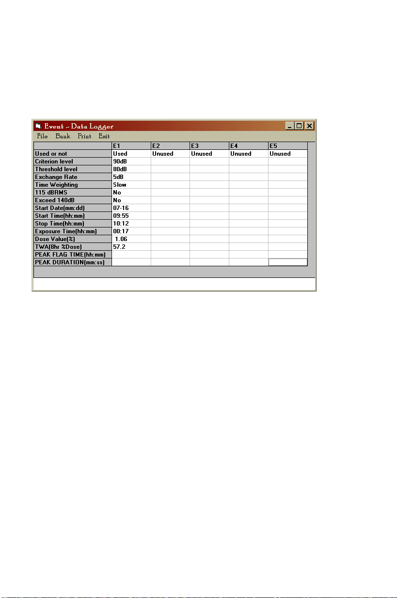
EVENT WINDOW - Download data from meter bank (E1 through E5) to PC
In this window the user can download, view, and save the contents of the meter’s Event
banks E1 through E5. Use the BANK tab to select one bank or all banks; this will
automatically start a download operation. Alternatively, simply click on a column to
initiate a download operation. The MENU headings are described below:
FILE: Save the event data in a file
BANK: Select one bank or all banks to initiate a download from meter to PC
PRINT: Click to print the data to the local printer
EXIT: Close the EVENT window
The Parameters shown in the left-most column of the EVENT window are explained
below:
USED OR NOT: Indicates that there are or are not data records in a particular
bank. The word RECORDING will appear if the meter is currently performing a
noise survey.
Criterion, Threshold, Exchange, and Time weighting are the settings configured by
the user for a noise survey as described previously.
115VdB RMS: Alerts the user that the sound level reached 115dB
EXCEED 140dB: Alerts the user that the sound level reached 140dB
START DATE and TIME: Date and time when noise survey began
STOP TIME: Time of day noise survey ended
EXPOSURE TIME: Duration of test
DOSE VALUE: Dose value in percent for the period of the test
TWA: Projected sound level in dB. In the example above, the elapsed time of the
noise exposure test is only 17 minutes; much shorter than an 8-hour test. However,
if sound levels remain relatively constant for the next 8 hours, the projected sound
level average will be 57.2 dB.
PEAK FLAG TIME: Time of day when sound level reached 115dB
PEAK DURATION: Interval of time that sound level was equal to or greater than
115dB
11
Model 407355 Version 2.1 September 2004

AVERAGE
When AVERAGE is selected
the window shown in the
accompanying diagram
opens. In the AVERAGE
mode, the user selects a
sampling interval and the
software shows a value that
represents the average of all
the readings taken during the
sampling interval.
The USER field can be used to personalize the data record (optional).
The DATE field is automatically filled-in with the START DATE/TIME and the
user-selected Time Interval (time between records).
The METER SET TO field is automatically filled-in with the Criterion level and
Exchange rate. If these fields do not automatically fill in, go to the EVENTS menu
item and download the EVENT register information.
The MEASUREMENT SUMMARY window automatically fills in when the test is
stopped. The RUN TIME is total test time. The SPL MAX field is highest average
reading taken during the course of the test. The DOSE field automatically fills in
the %DOSE value for the test (in noise survey mode).
OPTION
TWA (Time Weighted Average) Information Window
TWA is the 8-hour projected average sound level in dB based on data collected from the
start of the test up to the time the TWA is checked. See the information window below.
TWA is automatically calculated in the EVENTS window, discussed previously.
Average Readings
Time stamps
12
Model 407355 Version 2.1 September 2004

OCCUPATIONAL NOISE EXPOSURE STANDARD Window
The Occupational Noise Exposure Standard window (see diagram) is a convenient way
to automatically set up the meter’s noise survey parameters for a given country. Simply
click on the desired country and then click the SET button. It may take a minute or so for
the operation to complete.
SET MODE
The Set Mode is used to change the noise survey parameters and the Time/Date (see
diagram). Select the desired settings and press the OK button when finished. It may
take several minutes for the operation to complete.
13
Model 407355 Version 2.1 September 2004
Test Equipment Depot - 800.517.8431 - 99 Washington Street Melrose, MA 02176
FAX 781.665.0780 - TestEquipmentDepot.com

r
PC Interface Cable and Adaptor Wiring Reference
The wiring diagrams and pin-outs for the supplied PC Interface cable and the supplied 9-pin
to 25-pin adaptor are provided below:
DIN Connector
end of supplied cable
PIN 2 PIN 2 RX
PIN 3 PIN 3 TX
PIN 4 PIN 4 DTR
PIN 5 PIN 5 GND
PIN 6 DSR
PIN 1 PIN 7 RTS
PIN 8 CTS
DB-9 end of
supplied cable
DIN to DB-9 Cable 9-PIN to 25-PIN Adapto
PIN 1 PIN 8 FG
PIN 2 PIN 3 RXD
PIN 3 PIN 2 TXD
PIN 4 PIN 20 DTR
PIN 5 PIN 7 GND
PIN 6 PIN 6 DSR
PIN 7 PIN 4 RTS
PIN 8 PIN 5 CTS
PIN 9 PIN 22 RI
Battery Replacement and Status Display
The 407355 is powered by four (4) ‘AAA’ 1.5V batteries and the LCD display employs a 5segment battery status indicator.
5-segment battery LCD status indicator
When the batteries are fully charged, all five segments of the indicator will be visible. As
the batteries discharge, the segments switch off one by one. Do not use the instrument if
all five segments have switched off.
To replace the batteries:
1. Remove the large flat-head screw from the back of the instrument. This will free the
belt clip; remove the clip.
2. The discharged 1.5V ‘AAA’ batteries will be visible behind the clip.
3. Replace the batteries observing polarity.
4. Re-assemble the clip
14
Model 407355 Version 2.1 September 2004

Conversion Charts
OSHA Permissible Noise Exposures
Duration per day, hours Sound level dBA, slow response
8 90
6 92
4 95
3 97
2 100
1.5 102
1 105
0.5 110
0.25 or less 115
Source:29 CFR 1910 Table G-16
Conversion from Percent Noise Exposure or Dose to 8-Hour Time Weighted Average
Sound Level(TWA)
Dose or percent TWA (dBA)
50 85.0
55 85.7
60 86.3
65 86.9
70 87.4
75 87.9
80 88.4
85 88.8
90 89.2
95 89.6
100 90.0
105 90.4
110 90.7
115 91.1
120 91.3
125 91.6
Note: Assumes 5-dB exchange rate and 90-dBA Criterion
15
Model 407355 Version 2.1 September 2004
Test Equipment Depot - 800.517.8431 - 99 Washington Street Melrose, MA 02176
FAX 781.665.0780 - TestEquipmentDepot.com
 Loading...