

Page 1
99 Washington Street
Melrose, MA 02176
Phone 781-665-1400
Toll Free 1-800-517-8431
Visit us at www.TestEquipmentDepot.com
Back to the Extech 461950 Product Page
User Guide
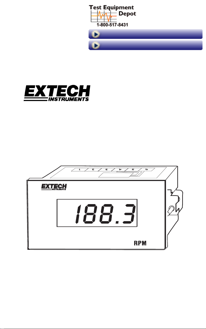
Panel Mount Digital Tachometer
Model 461950
Test Equipment Depot - 800.517.8431 - 99 Washington Street Melrose, MA 02176
FAX 781.665.0780 - TestEquipmentDepot.com
Page 2
Introduction
Congratulations on your purchase of the Extech 461950 Panel Tachometer. This meter
displays continuous readings from 5 to 99,990 rpm. Single pulse activation eliminates the
need for special gears when setting up the meter in any given application. Models 461955
(proximity sensor) and 461957 (photoelectric sensor) are also covered in this manual.
Careful use of these devices will provide years of reliable service.
Specifications
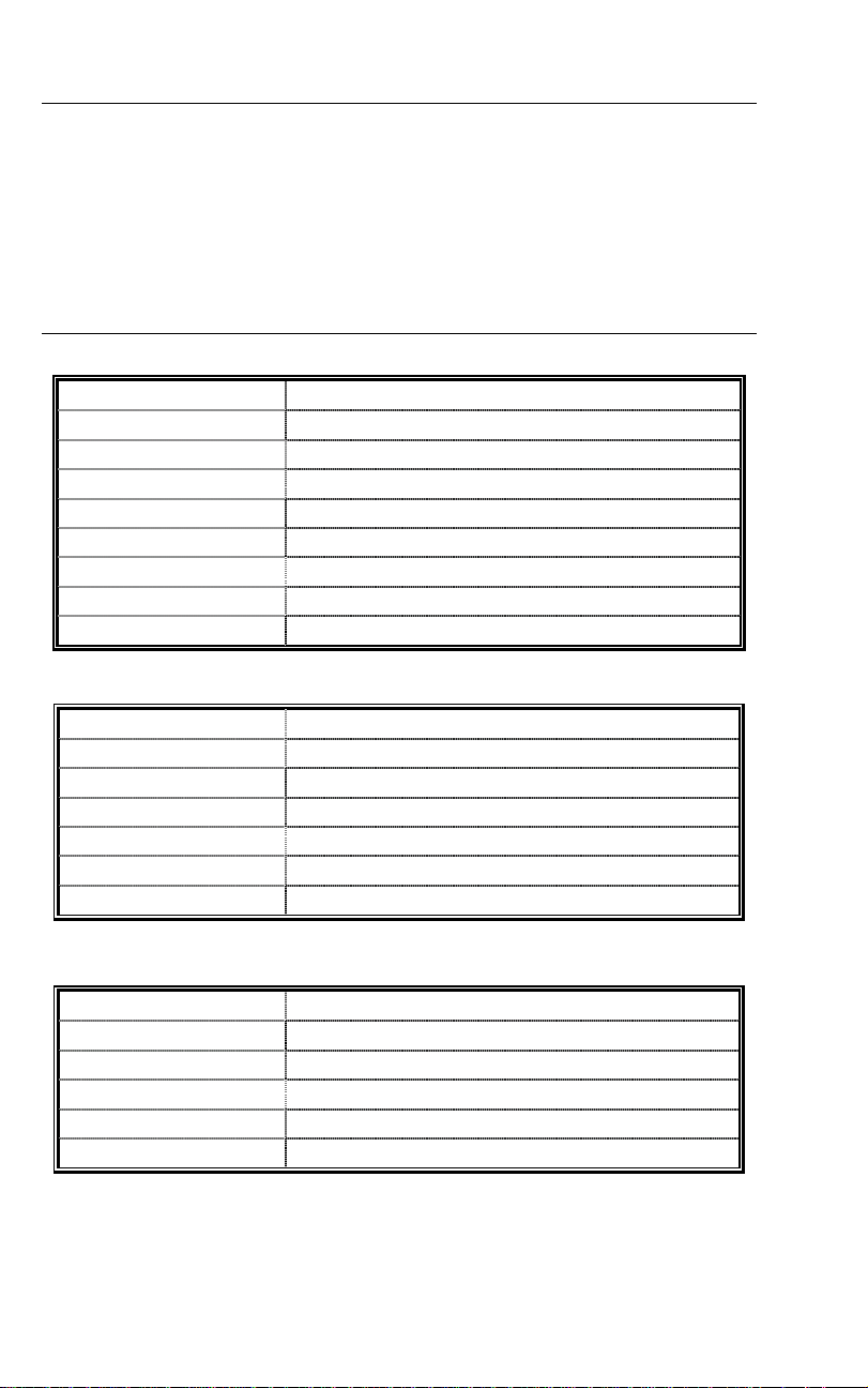
Model 461950 Panel Tachometer
Range
5 to 99,990 RPM
Resolution 0.1 (5 to 999.9); 1 (1000 to 9999); 10 (10.000 to 99,990)
Accuracy 0.05% + digit (of reading)
Display 0.5 " (13mm) 4-digit (9999 count) LED display
Display update rate Once per second
Power 110/220VAC; 50/60Hz ±15%
Panel cutout dimensions 3.62 x 1.77" (92 x 45mm)
Bezel dimensions 3.78 x 1.89 x 2.36" (96 x 48 x 60mm)
Meter dimensions/Weight 3.61 x 1.66 x 3.54" (92 x 42 x 90mm); 13.9 oz. (397 g)
Model 461957 Photoelectric Sensor
Range Up to 6000 RPM (100 Hz)
Power 12 - 24VDC ±10%; Consumption: 40mA max.
Response time < 1ms
Output NPN transistor; Max load 80mA
Photo beam color Green
Photo beam wavelength 5500 Angstroms
Cable length 6 ft (1.8 meters)
Model 461955 Proximity Switch
Range Up to 36,000 RPM (600 Hz)
Power 12 – 24VDC ±10%
Power Consumption 10mA max.
Object distance detection 0.1" (3 mm) maximum target distance
Object size detection 0.07 x 0.11" (2 x 3 mm) minimum size detected
Cable length 6 ft (1.8meters)
Model 461950 Version 2.0 March 2005 2
Page 3
Mounting Instructions
Panel Meter Mounting
1. The 461950 dimensions are:
Meter: 3.61 x 1.66 x 3.54 " (92 x 42 x 90 mm)
Bezel: 3.78 x 1.89 x 2.36 " (96 x 48 x 60 mm)
2. Prepare a panel cutout with the following dimensions: 3.62 x 1.77" (92 x 45 mm).
3. The Tachometer will fit a standard 1/8 DIN cutout. Mounting hardware is provided
which attaches to the sides of the meter. The screws attached to the mounting
bracket should be tightened to the back of the panel (avoid over-tightening which can
bow the meter housing).
Proximity Switch Model 461955 Mounting
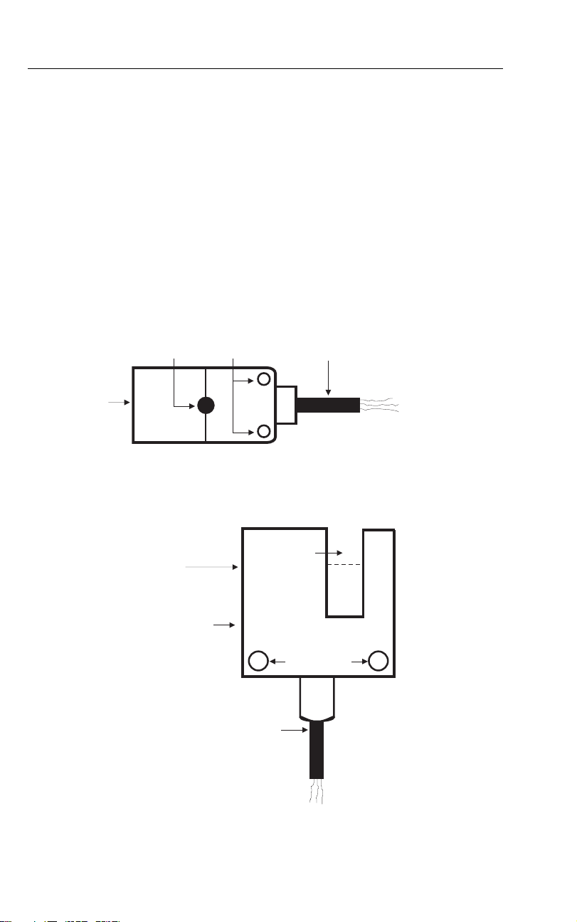
Use the mounting holes to secure the proximity switch to the desired surface. The sensor
is the side of the switch that detects a moving metal object such as a gear tooth or a fan
blade. The sensor side of the switch has an X on it and is located on the opposite side of
the switch from the wiring cable. Refer to the top view diagram below. The Proximity switch
must be mounted so that the object being detected passes within 0.16" (4mm) of the
sensor side of the switch. The pulse LED will light when the sensor detects a metal object.
Pulse LED
Sensor
Photoelectric Sensor Model 461957 Mounting
Use the mounting holes to secure the photoelectric sensor to the desired surface. The
photo beam is generated and detected in the groove (as depicted by the dotted line in the
diagram below). The object under test must pass in the groove so that the light beam can
be interrupted.
Power / Detection
LEDs
Mount holes
+
+
Cabling
Sensor
Sensitivity
Adjust
Mount Holes
++
Cable
Model 461950 Version 2.0 March 2005 3
Test Equipment Depot - 800.517.8431 - 99 Washington Street Melrose, MA 02176
FAX 781.665.0780 - TestEquipmentDepot.com
Page 4

Wiring Instructions
The Model 461950 has seven screw terminals for AC power, sensor input, and sensor
excitation.
Model 461955 Proximity Switch Wiring
1. Brown wire (10 - 30V supply signal) to terminal 3 on the panel tachometer (+12V)
2. Black wire to terminal 2
3. Blue wire to terminal 1
Model 461957 Photoelectric Sensor Wiring
1. Brown wire connects to terminal 3 of the panel tachometer
2. Blue wire connects to terminal 1
3. Black wire (sensor output during high to low transition) or Green wire (sensor output
during low to high transition) connects to terminal 2. Connect one wire only to terminal
2 (black or green) depending upon which better suits the application.
AC Power Wiring
Meter terminals 5, 6, and 7, are for AC power connections. Connect to terminals 5 and 7
for 220V applications. Connect to terminals 6 and 7 for 110V power applications. A
Wiring Diagram
NOTE: Fusing and electrical noise preventative devices such as MOVS, RC networks, and
line filters should be considered by the user when installing to avoid electrical noise
interference.
SENSOR INPUT POWER INPUT
GND POS +12V 220V 110V
N.C.
Neutral
1234567
Model 461950 Version 2.0 March 2005 4
Page 5

Meter and Sensor Operation
Meter Operation
Mount and wire the meter as previously described. The Model 461950 Panel Mount
Tachometer was designed to measure and display RPM in the following ranges:
Resolution
Ranges
5 – 999.9 rpm 0.1 rpm
Accuracy (of rdg)
±(0.05% + 1 digit)
1000 - 9999 rpm 1 rpm
10,000 - 99,990 rpm 10 rpm
Extech sensors generate pulses that are counted by the meter and converted to RPM. The
meter computes RPM values based on the number of pulses detected in a given period of
time and provides an RPM display on the 4 digit (9999 count) LED.
Operation of the Proximity Switch Model 491955
The Extech Proximity Switch Model 461955 connects directly to the tachometer's input
terminals and measures up to 36,000 RPM (600 Hz). Proximity switches detect magnetic
(ferrous) objects as they pass the sensor, sending a pulse, one for each pass, to the
meter. The pulse LED on the switch lights with each pass. The meter then calculates RPM
and updates the LED display.
Operation of the Photoelectric Sensor Model 461957
Extech Photoelectric Sensor Model 461957 connects directly to the tachometer's input
terminals and measures up to 6,000 RPM (100Hz). When the sensor is properly powered
(by the voltage on terminal 3 of the meter), the green power LED (on the sensor) will
switch on.
Photoelectric sensors generate a light beam that is interrupted by an object as it passes
through the beam. Each time the beam of light is interrupted a pulse is transmitted to the
meter and the red status LED on the sensor blinks. The meter then calculates and displays
the RPM based on the number of pulses received in a specific period of time.
The sensitivity adjustment screw on the sensor may have to be adjusted so that one pulse
is generated for each interruption of the light beam. If the red LED turns on less/more than
once for each interruption of the beam, adjust the sensitivity screw.
Model 461950 Version 2.0 March 2005 5
Test Equipment Depot - 800.517.8431 - 99 Washington Street Melrose, MA 02176
FAX 781.665.0780 - TestEquipmentDepot.com
 Loading...