

User's Guide
Visit us at www.TestEquipmentDepot.com
99 Washington Street
Melrose, MA 02176
Phone 781-665-1400
Toll Free 1-800-517-8431
Back to the Extecch 407119 Product Page
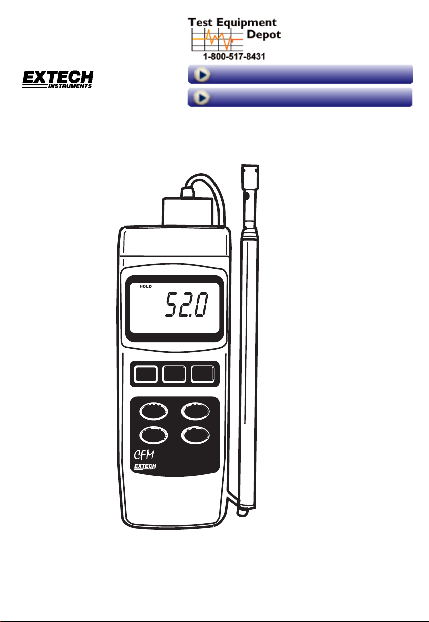
Heavy Duty Hot Wire CFM Thermo-Anemometer
Model 407119A
CFM
Ft/min73.2 F
HOLD
POWER
UNIT / ZERO
AVERAGE
Hot W ire
Anemometer
REC.
ESC
Enter
FUNCTION
AREA
SETUP
407119A
Test Equipment Depot - 800.517.8431 - 99 Washington Street Melrose, MA 02176
FAX 781.665.0780 - TestEquipmentDepot.com

warranty, whether written or oral, is expressed or implied.
Introduction
Congratulations on your purchase of the Extech 407119A Thermo-Anemometer. The
407119A measures air velocity, air volume, and air temperature. It uses a telescoping
probe antenna to allow convenient access to grills and diffusers. Careful use of this
meter will provide years of reliable service. The Model 407119A features are listed
below.
Features
• Combination hot wire probe (for air velocity) and thermistor sensor (for temperature)
deliver rapid and precise measurements even at low air velocity values.
• Slim probe design with telescoping antenna for easy grill and diffuser access
• Air Velocity, Air Volume, and Air Temperature measurements
• 20 Reading Average feature
• Zero adjustment
• Data Hold and Record/Recall Max/Min features
• Auto Power OFF
• PC Interface (RS-232) with optional software and cable for data acquisition
Applications
Environmental testing, air conveyors, flow hoods, clean rooms, air balancing,
fans/motors/blowers, furnace velocity, paint spray booths, and others.
Model 407119A Version 5.0 October 2005 2
Specifications
General Specifications
Display Dual function 5-digit LCD
Measurement units Air Velocity: m/s, km/h, ft/min, knots, mph;
Air Flow: CMM (m
Data hold Freezes displayed reading
Sampling rate Display update rate:1 second (approx.)
Sensors Air velocity and temperature sensors: Thermistor type
MAX/MIN Memory Record and view Maximum and Minimum readings
Average feature Averages up to 20 readings
Automatic Power off Auto shut off after 15 minutes
Data Output RS-232 PC serial interface with 16-bit data stream output
Operating Temp. 32 to 122°F (0 to 50°C)
Operating Humidity Max. 80% Relative Humidity
Power Supply Four (4) ‘AA’ 1.5V batteries or optional AC adaptor
Power Current 70mA DC (approx.)
Weight (meter only) 1.15 lbs. (521g) with batteries installed
Dimensions Main instrument: 7.9 x 3.0 x 1.5" (200.0 x 76.2 x 36.8mm)
Telescoping Sensor: 0.5" (12.7mm) diameter head
Min length of sensor: 8” (260mm); Max. length: 37” (0.94m) with 5.5’
(1.7m) cable
3
/min) and CFM (ft3/min);Temperature: °C and °F
Range Specifications
Air Velocity Range Resolution Accuracy (of rdg)
m/s (meters per second) 0.2 – 17.0 m/s 0.1 ±(5% + 5 digits)
km/h (kilometers per hour) 0.7 – 61.2 km/h 0.1 ±(5% + 20 digits)
ft/min (feet per minute) 40 – 3346 ft/min 1 ±(5% + 100 digits)
mph (miles per hour) 0.5 – 38.0 mph 0.1 ±(5% + 10 digits)
Model 407119A Version 5.0 October 2005 3
Test Equipment Depot - 800.517.8431 - 99 Washington Street Melrose, MA 02176
FAX 781.665.0780 - TestEquipmentDepot.com
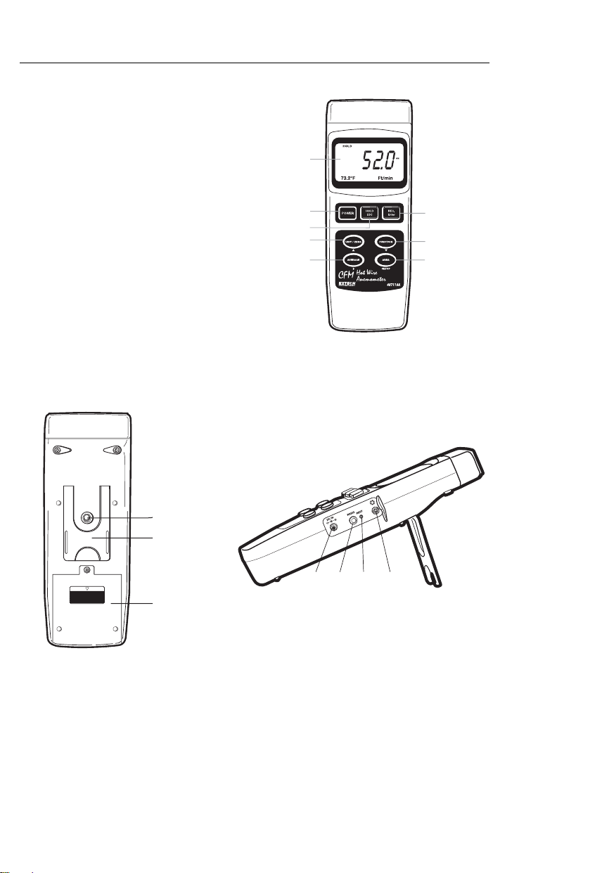
Meter Description
1. Display
2. POWER button
3. HOLD and ESC button
4. REC and ENTER button
5. UNIT, ZERO, and ▲up arrow button
6. Function and ▼down arrow butt on
7. AVG. START, CLEAR, and ►right arrow button
8. AREA SET button
9. Tilt stand
10. Battery compartment / Cover
11. Tripod mount
12. LCD contrast adjustment pot
13. System reset switch
14. RS-232 Output terminal
15. DC9V power adaptor
1
2
4
3
5
7
6
8
11
10
9
13
15
Model 407119A Version 5.0 October 2005 4
14
12

Operation
Initialization and Zero procedures (please follow these steps before use)
Important Note
be in the locked position (with the probe inserted) for
the meter to turn on and operate correctly. Refer to the
accompanying diagram or the diagram at the top of the
meter for switch orientation.
For the best accuracy and for proper operation, the
following steps must be performed.
1. Connect the sensor to the input jack on top of the
meter by first unlocking the sensor jack and then
inserting the sensor plug. Lock the sensor jack after
the probe is inserted.
2. Press the POWER button to turn on the meter. The meter will perform a self-test during
which the display will count down from 9999 to 0000.
3. Select the air velocity function using the FUNCTION button. The LCD will display the
most recently selected unit of measure for air velocity.
4. To change the temperature units of measure (C/F), use the advanced programming
mode discussed later in this manual.
5. Momentary presses of the UNIT button changes the air velocity units. The LCD will
reflect the selection.
6. Place the sensor cover in the up (ZERO) position (see diagram below).
7. Open the telescoping sensing antenna to a convenient length.
8. Place the sensor in the area to be measured and allow a short time for it to stabilize to
the ambient temperature.
9. To Zero the meter display, press and hold the ZERO button until the second beep.
: The meter’s probe locking switch must
TOP VIEW OF METER
LOCKED Position
UNLOCKED Position
Warning! Do not touch the air velocity or temperature thermistors inside the sensor head
while moving the sensor cover.
Model 407119A Version 5.0 October 2005 5
Test Equipment Depot - 800.517.8431 - 99 Washington Street Melrose, MA 02176
FAX 781.665.0780 - TestEquipmentDepot.com

Air Velocity Measurements
1. Follow the Initialization and Zeroing procedures above before continuing.
2. Open the antenna to the desired length.
3. Slide the air velocity sensor cover down.
4. Press the POWER button to turn the meter on.
5. Place the sensor in the air
current to be measured.
Have the air flow meet the
sensor head in the
direction of the white dot
(as shown in diagram).
6. View the air velocity and temperature readings on the LCD Display. The large main
LCD display shows the Air Velocity reading. The lower LCD sub-display shows the
temperature reading (left) and the unit of measure (right).
7. To turn the meter off, press and hold the POWER button until the meter switches off.
Air Flow (Volume) Measurements (CMM / CFM)
NOTE: Temperature is not displayed while the meter is in the Air Flow mode.
1. Follow the steps in the Initialization and Zeroing section before continuing.
2. Select the air flow mode using the Function button. The LCD will display CMM (cubic
meters per minute) or CFM (cubic feet per minute) when Air Flow is selected.
3. Press the UNIT button momentarily to select the desired air flow units: CMM or CFM.
The LCD display will reflect the selection.
4. Calculate the area of the duct or vent under test (refer to the Useful Conversions and
Equations section in the back of this manual for assistance). Be sure to compute the
area of the vent or duct in square feet or meters. If you have the area in inches, convert
inches to feet before programming the meter with the area value.
5. Press the AREA SET button to begin entering the area in m
2
or ft2. The left digit will
begin flashing. Follow the steps below to enter the area of the duct or vent in question:
Use the ► button to select a digit to change (digit will flash)
Use the ▲ button increase the value of the flashing digit
Use the ▼ button to decrease the value of the flashing digit
6. Press the REC/Enter button and then the AREA SET button to save the new area
value
7. After the area has been entered, the new area value will be shown on the lower left of
the LCD display in ft
2
or m2. If the unit of measure is CFM, the area will be shown in
square feet. If the unit of measure is CMM, the area will be shown in meters squared.
8. Press the ESC button to abort the programming at any time.
9. Place the probe in the area under test. The main LCD digits will indicate the air flow in
CFM or CMM. If the CFM or CMM reading exceeds 99999, use the displayed X10
multiplier to calculate the reading.
10. To turn the meter off, press and hold the POWER button until the meter switches off.
Model 407119A Version 5.0 October 2005 6

AVERAGE Feature for the Air Flow Mode
In the Average mode, up to 20 readings can be stored and averaged.
1. In the Air Flow Mode (discussed earlier), press the FUNCTION button momentarily
until the AVG icon and a ‘zero’ appears on the lower LCD display line.
2. Press the AVG START button to record the current reading. A ‘1’ will appear on the
lower LCD line indicating that one reading has been stored.
3. Press the AVG START for up to a total of 20 measurements. The number on the lower
LCD line will increment with each press of the AVG START button letting the user
know how many readings are currently being averaged. Note that only the averaged
reading is shown while in this mode, not the actual reading.
4. To clear (erase) all of the currently stored readings and start again, press and hold the
AVG button until the meter beeps twice. Note that the counter resets to ‘0’ and that the
meter is ready to start another averaging session.
5. Use the FUNCTION button to exit this mode of operation.
Data Hold Feature
1. While taking measurements, press the HOLD button to freeze a reading.
2. The HOLD indicator will appear on the LCD when the display is in Data Hold mode.
3. Press HOLD again to return to normal operation.
Maximum (MAX) and Minimum (MIN) Recording
The MAX / MIN Record-Recall feature allows the user to record and view the highest and
lowest readings during a measurement session.
1. Press the REC button once. The REC indicator will appear on the display and the
meter will begin keeping track of the MAX and MIN values.
2. To view the MAX reading, press REC again. The MAX indicator along with the
maximum reading will appear on the LCD display.
3. Press REC again to view the minimum value, the MIN indicator along with the
minimum reading will appear on the LCD display.
4. To return to normal operation, press and hold the REC button for approx. 3 seconds
(until the meter beeps). The display indicators REC, MAX, and MIN will disappear.
Note: Auto Power Off is disabled in the RECORD mode.
Auto Power Off
To save battery life, the meter will automatically shut off after approximately 15 minutes of
operation. To temporarily disable this feature (until the meter’s power is cycled), press the
REC button and enter the RECORD mode. Alternatively, go to the advanced programming
section (later in this manual) for instructions on how to disable it long term.
Model 407119A Version 5.0 October 2005 7
Test Equipment Depot - 800.517.8431 - 99 Washington Street Melrose, MA 02176
FAX 781.665.0780 - TestEquipmentDepot.com

Advance Programming Mode
From the Air Velocity mode of operation, press and hold the SET button until the meter
beeps and a ‘1’ is displayed. The advanced programming mode is now accessed. The
Auto Power OFF Enable/Disable and the Temperature Units selections are available in the
advanced programming mode. Use the ESC button to exit this mode at any time.
Auto Power Enable/Disable
The first parameter in the advanced mode is the Auto Power OFF enable/disable. Use the
up and down arrow keys to select the desired value. ‘0’ defeats the Auto Power OFF
feature; ‘1’ enables the Auto Power OFF feature. Momentarily press the SET button to
move to the next parameter temperature units (see below).
Temperature Units selection (C/F)
The second parameter in the advanced mode is the Temperature Units selection. Use the
up and down arrow keys to select the desired value. ‘0’ selects degrees ‘C’; ‘1’ selects
degrees ‘F’. Press the ESC button to exit the advanced programming mode.
System Reset
If the meter’s display ‘locks up’ and/or the button presses do not cause the display to
change, try a system reset. To reset the meter, use one of the following methods.
1. Move the probe lock switch from the ON to the OFF to the ON position again. Turn the
meter on.
2. While powering the meter, press the RESET switch (side compartment) using the point
of a paper clip.
Model 407119A Version 5.0 October 2005 8

PC Interface
The 407119A is equipped with a 3.5mm jack (side compartment) for connection to a PC for
data acquisition purposes. The meter’s data output is a 16 bit data stream. To obtain PC
interface cabling and Windows
Instructions for use are provided with the software. The PC interface cable schematic, data
stream protocol, and RS-232 communication settings are provided below.
PC Interface Cable schematic
Protocol for 16-bit data stream
D0 End Word = ‘0D’
D1 & D8 Displayed reading; D1 = LSD; D8 = MSD. For example,
D9 Decimal point (right to left):
D10 Polarity: 0 = positive; 1 = negative
D11 & D12 Displayed unit of measure: 01 = oC; 02 = oF; 08 = m/s; 09 = knots;
D13 1 = Upper LCD display digits; 2 = Lower LCD display digits
D14 Always ‘4’
D15 Start word ‘02’
RS-232 Settings
Baud rate: 9600
Parity: No parity
Data bits: 8
Stop bits: 1
Meter
3.5mm jack
Center pin.............................Pin 4
Ground / Shield.....................Pin 2
For a displayed reading of 1234, D8 through D1 is 00001234
0 = no decimal; 1 = 1 place; 2 = 2 places; 3 = 3 places
10 = km/hr; 11 = ft/min; 12 = MPH; 84 = CMM; 85 = CFM;
0A = Square meter (area); 0B = Square feet (area)
TM
data acquisition software, contact Extech Instruments.
PC
DB-9 pin
2.2K
W
Resistor
Pin 5
Model 407119A Version 5.0 October 2005 9
Test Equipment Depot - 800.517.8431 - 99 Washington Street Melrose, MA 02176
FAX 781.665.0780 - TestEquipmentDepot.com

Battery Replacement
When the battery icon appears on the lower left corner of the LCD display, the four (4) ‘AA’
batteries must be replaced.
1. Remove the rear Phillips head screw
2. Slide off the rear battery compartment
3. Replace the batteries
4. Secure the battery compartment
Calibration and Repair Services
Support line (781) 890-7440
Technical support: Extension 200; E-mail: support@extech.com
Repair & Returns: Extension 210; E-mail: repair@extech.com
Product specifications subject to change without notice
For the latest version of this User’s Guide, Software updates, and other
up-to-the-minute product information, visit our website: www.extech.com
Extech Instruments Corporation, 285 Bear Hill Rd., Waltham, MA 02451
99 Washington Street
Melrose, MA 02176
Phone 781-665-1400
Toll Free 1-800-517-8431
Visit us at www.TestEquipmentDepot.com
Back to the Extecch 407119 Product Page
Model 407119A Version 5.0 October 2005 10

Useful Equations and Conversions
Area equation for rectangular or square ducts
Height (H)
Width (W)
Area (A) = Width (W) x Height (H)
Area equation for circular ducts
Radius
Cubic equations
CFM (ft3/min) = Air Velocity (ft/min) x Area (ft2)
3
CMM (m
/min) = Air Velocity (m/sec) x Area (m2) x 60
NOTE: Measurements made in inches
must be converted to feet or meters
Unit of Measure Conversion Table
m/s ft/min knots km/h MPH
Area (A) =
= 3.14 and r
Where
before using the above formulae.
x r
2
2
= radius x radius
1 m/s 1 196.87 1.944 3.6 2.24
1 ft/min 0.00508 1 0.00987 0.01829 0.01138
1 knot 0.5144 101.27 1 1.8519 1.1523
1 km/h 0.2778 54.69 0.54 1 0.6222
1 MPH 0.4464 87.89 0.8679 1.6071 1
Model 407119A Version 5.0 October 2005 11
Test Equipment Depot - 800.517.8431 - 99 Washington Street Melrose, MA 02176
FAX 781.665.0780 - TestEquipmentDepot.com
 Loading...