

Page 1

User's Manual
Model 401025
Digital Light Meter
Visit us at www.TestEquipmentDepot.com
Back to the Extech 401025 Product Page
Introduction
Congratulations on your purchase of Extech’s Digital Light Meter. This professional meter,
with proper care, will provide years of safe reliable service.
99 Washington Street
Melrose, MA 02176
Phone 781-665-1400
Toll Free 1-800-517-8431
Page 2

Specifications
General Specifications
Display 0.5" (13 mm) LCD (Liquid Crystal Display).
Measurement Lux, Ft-candle (Fc).
Ranges Lux: 0 to 50,000 Lux, 3 ranges. Foot-candle: 0-5,000 Fc, 3
Sensor Exclusive photo diode & color correction filter, spectrum
Zero Adj. Manual adjustment.
Sampling Time Approx. 0.4 sec.
Response Time Fast: 0.25s; Slow: 1s
Over input indication Indication of "1 "
Analog Output 0.1 mV/1 digit, max. output :200mV.
Operating Temperature (32OF to 122OF).(0OC to 50OC).
Operating Humidity Less than 80% RH.
Power Supply 006P DC 9V battery
Power Current Approx. 2 mA DC
Weight 220 g / 0.52 LB
Dimension Main instrument: 6.4x2.8x1.2 inch (163x70x30mm).
Optional Accessories Vinyl pouch carrying case, 409996
Range Specifications
Lux
Range In-range Display Resolution Accuracy
2,000 Lux 0-1,999 Lux 1 Lux ± (5% + 2digits)
20,000 Lux 2,000-19,990 Lux 10 Lux ± (5 % + 2digits)
50,000 Lux 20,000-50,000 Lux 100 Lux ±- (5 % + 2digits)
Foot-candle (Fc)
Range In-range Display Resolution Accuracy
200 Fc 0-199.9 Fc 0.1 Fc ± (5% + 2digits)
2,000 Fc 200-1,999 Fc 1 Fc ± (5% + 2digits)
5,000 Fc 2,000-5,000 Fc 10 Fc ± (5% + 2digits)
Frequency Spectrum
1
0.8
0.6
0.4
0.2
0
300 400 500 600 700 800
ranges.
designed to meet C. I. E.
Sensor Probe: 3.2x2.2x0.5 inch (85x55x12 mm).
Wavelength (nm)
Test Equipment Depot - 800.517.8431 - 99 Washington Street Melrose, MA 02176
FAX 781.665.0780 - TestEquipmentDepot.com
2
401025 Ver. 2.1 07/05
Page 3
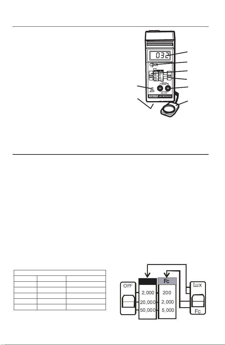
Meter Description
1. LCD Display
2. Data Hold Switch
3. Power Off/Range Switch
4. Analog Output Terminal
5. Battery Compartment (rear)
6. LUX/Fc Switch & Response Switch
7. Light Sensor
8. Zero adjust
8
5
Operation
1. Select Units (Lux or Ft-candle) and Response Time (Fast or Slow) on the slide
switch. Typical selection is Slow and Fc using the gray lettering.
2. Select the maximum range on the "Range Switch"
3. Hold the "Light Sensor" so that the sensor faces the light source to be measured.
4. The Display will indicate measured values. Use a range display multiplier if on the
Lux 20,000 and 50,000 ranges or on the Fc 5000 range.
5. To "hold" a measurement, slide the "Data Hold Switch" to the "hold" position. The
reading will "freeze" in the display until the "Data Hold Switch" is released.
Note 1: An Over Range indication is a display of "I ". If this occurs, switch to a higher
range.
Note 2: For measurements made on the Fc 5000 range, the displayed reading must be
multiplied by 10.
Note 3: For measurements made on the Lux 20000 or 50000 range, the displayed
reading must be multiplied by 10 and 100 respectively.
Note 4: The meter will indicate values above the maximum ranges. The accuracy of
these measurements is unknown.
Range Display Multipliers
Range Units Multiplier
200 Fc Direct reading
2000 Fc & Lux Direct reading
5000 Fc Reading x10
20,000 Lux Reading x10
50,000 Lux Reading x100
Example: If a measurement on the 5000 Fc range displays 350, then the actual
measured value is; 350 X 10 = 3500 Fc.
3
Lux
401025 Ver. 2.1 07/05
1
2
3
6
4
7
Page 4
Selecting a Measurement Range
The meter has three measurement ranges (0-200, 0-2000, and 0-5000 Fc) and (0-2000, 020000, and 0-50000) Lux). The proper range selection will produce the most accurate
reading. Always select the range that produces the maximum number of digits without
exceeding the maximum count for that particular range. For example, a reading of 1456 Fc
should be read on the 0 - 2000 range, not the 0-5000 range.
Zero procedure
The meter zero (display with no light input) may change with time. Occasional checking and
adjustment may be required.
1. Completely cover the sensor to block out any light.
2. Set the range switch to the lowest Lux or Fc range
3. Using a small screwdriver, adjust the “Zero” control for a zero display. The last digit
may change slightly. This is normal and does not affect the accuracy of the meter.
Analog Output
The analog output jacks on the front panel produce a 0.1mV DC per digit signal that can be
used for recording or datalogging purposes.
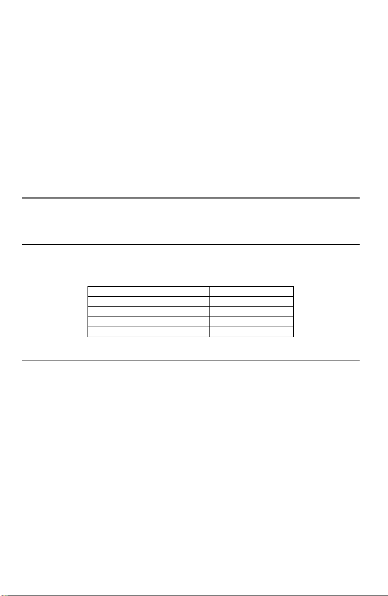
Lighting Type Correction Factors
The 401025 light meter is calibrated under a precise "Standard tungsten light source of
O
2856
K". If the meter is to be used under a different type of light the correction factor of from
the table below should be applied to the readings obtained.
Mercury Lamp x1.14
Fluorescent Lamp X0.92 to 1.12
Daylight x1.00
Sodium x1.22
Metal Halide x1.00
Replacing the Battery
When the left corner of the LCD display shows "LO BAT", it indicates the battery output is
below the design limit and the battery needs to be replaced. However, reliable measurement
can still be taken for another few hours before the tester becomes inaccurate.
1. Open the Battery Cover at the back of tester and remove the battery.
2. Replace with a 9V battery and install the cover.
Test Equipment Depot - 800.517.8431 - 99 Washington Street Melrose, MA 02176
FAX 781.665.0780 - TestEquipmentDepot.com
4
401025 Ver. 2.1 07/05
Page 5
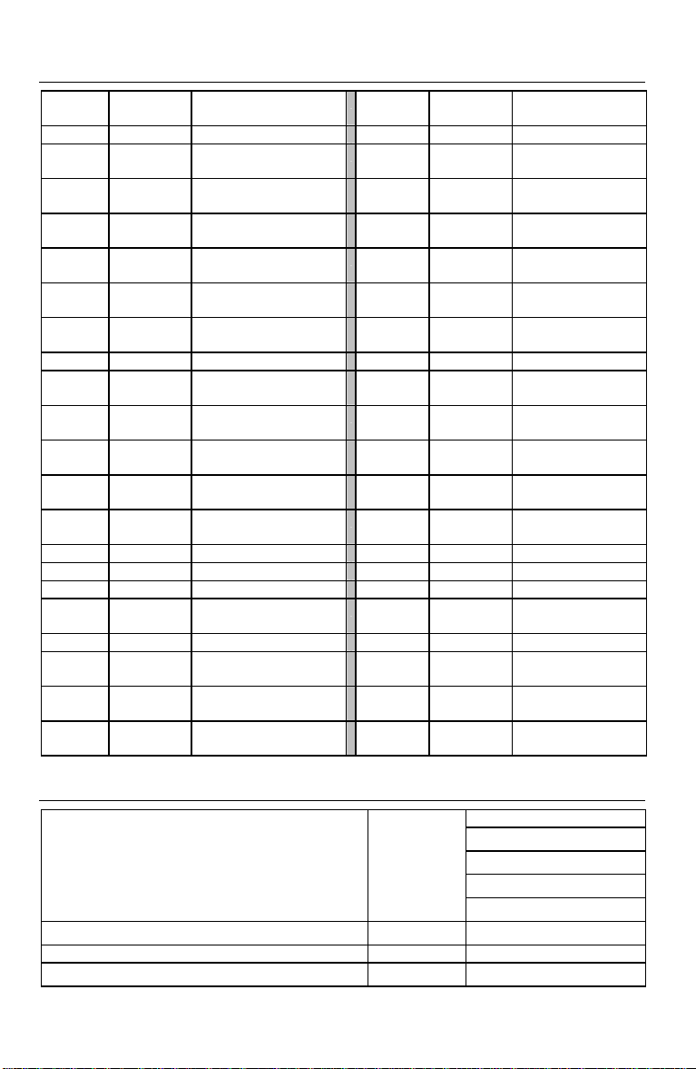
Appendix A: Typical Light Levels
Lux Foot
Factories Home
20-75 2-7 Emergency Stairs,
75-150 7-15 Exit/Entrance
150-300 15-30 Packing Work 200-300 20-30 Drawing Room,
300-750 30-75 Visual Work:
750-
1,500
1,5003,000
Office Restaurant
75-100 7-10 Indoor Emergency
100-200 10-20 Corridor Stairs 150-300 15-30 Entrance, Wash
200-750 20-75 Conference,
750-
1,500
1,5002,000
Store Hospital
75-150 7-15 Indoors 30-75 3-7 Emergency Stairs
150-200 15-20 Corridor/Stairs 75-100 7-10 Stairs
200-300 20-30 Reception 100-150 10-15 Sick Room,
300-500 30-50 Display Stand 150-200 15-20 Waiting Room
500-750 50-75 Elevator 200-750 20-75 Medical Exam
7501,500
1,5003,000
Candles
75-150 Typesetting:
150-300 Electronic Assembly,
75-150 Clerical Work 750-1,500 75-150 Show Window
150-2000 Typing, Drafting
75-150 Show Window,
150-300 Storefront, Show
Lux Foot
Warehouse
Passages
Production Line
Inspection Work
Drafting
Stairs
Reception Room
Packing Table
Window
100-150 10-15 Washing
150-200 15-20 Recreational
300-500 30-50 Makeup
500-1,500 50-150 Reading, Study
1,000-
2,000
75-150 7-15 Corridor Stairs
300-750 30-75 Cooking/Dining
750-1,500 75-150 Operating Room
5,000-
10,000
Candles
100-200 Sewing
500-1000 Eye Inspection
Activities
Table
Room
Room
Warehouse
Room
Appendix B - Common Terms and Conversion Factors
Illuminance (Visible Flux Density)
Luminance (Visible Flux Density per Solid Angle)
Luminous Intensity (Visible Flux per Solid Angle) 1 lm/sr = 1 candella
Luminous Flux ( Visible Flux) 1 lumen (lm) =
1 lm/m2 =
1 lm/m2/sr = 1 candela/m2
1 lux (lx)
10-4 lm/cm2
10-4 phot (ph)
9.290 x 10⁻² lm/ft2
9.290 x 10⁻² foot-candles
1.464 x 10⁻³ watts @ 555 nm
6
401025 Ver. 2.1 07/05
 Loading...