

Page 1
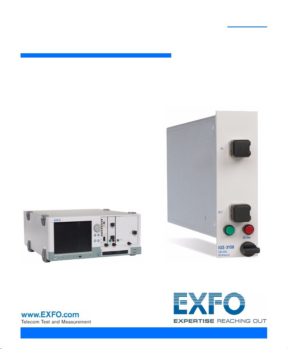
IQS-3150
Variable Attenuator for IQS Platforms
User Guide
Page 2

Copyright © 2006–2008 EXFO Electro-Optical Engineering Inc. All rights
reserved. No part of this publication may be reproduced, stored in a
retrieval system or transmitted in any form, be it electronically,
mechanically, or by any other means such as photocopying, recording or
otherwise, without the prior written permission of EXFO Electro-Optical
Engineering Inc. (EXFO).
Information provided by EXFO is believed to be accurate and reliable.
However, no responsibility is assumed by EXFO for its use nor for any
infringements of patents or other rights of third parties that may result from
its use. No license is granted by implication or otherwise under any patent
rights of EXFO.
EXFO’s Commerce And Government Entities (CAGE) code under the North
Atlantic Treaty Organization (NATO) is 0L8C3.
The information contained in this publication is subject to change without
notice.
Trademarks
EXFO’s trademarks have been identified as such. However, the presence
or absence of such identification does not affect the legal status of any
trademark.
Units of Measurement
Units of measurement in this publication conform to SI standards and
practices.
Patents
EXFO’s Universal Interface is protected by US patent 6,612,750.
Version number: 2.0.0
ii IQS-3150
Page 3

Contents
Contents
Certification Information ........................................................................................................v
1 Introducing the IQS-3150 Variable Attenuator ........................................... 1
Models and Options ...............................................................................................................1
Typical Applications ................................................................................................................3
Main Software Features ..........................................................................................................4
Conventions ............................................................................................................................8
Laser Safety Information .........................................................................................................9
2 Getting Started with Your Variable Attenuator ....................................... 11
Inserting and Removing Test Modules ..................................................................................11
Starting the Variable Attenuator Application ........................................................................15
Entering Values Using Sliders and Numeric Boxes .................................................................19
Exiting the Application .........................................................................................................20
3 Setting Up Your Variable Attenuator ........................................................ 21
Basic Settings ........................................................................................................................21
Control Center Settings and Controls ...................................................................................29
Creating a Test Sequence ......................................................................................................35
Managing Sequence Files .....................................................................................................42
Saving and Recalling Configurations .....................................................................................44
4 Operating the IQS-3150 ............................................................................. 47
Cleaning and Connecting Optical Fibers ...............................................................................47
Installing the EXFO Universal Interface (EUI) .........................................................................48
Nulling Electrical Offsets .......................................................................................................48
Running an Attenuation Sequence .......................................................................................50
Using the Power Tracking Function (Self-Adjusting Modules) ...............................................52
Using the Shutter ..................................................................................................................53
5 Controlling Multiple Variable Attenuators ............................................... 55
Starting a Multimodule Application ......................................................................................55
Selecting Modules to Control ...............................................................................................56
Controlling a Single IQS-3150 Variable Attenuator ...............................................................57
Navigating and Closing Multiple Module Windows ..............................................................58
6 Monitoring Variable Attenuator Modules ................................................ 59
Using Monitor Windows .......................................................................................................59
Using QuickTools ...................................................................................................................62
7 Measuring Multimode Insertion Loss ....................................................... 65
Variable Attenuator iii
Page 4

Contents
8 Maintenance ................................................................................................67
Cleaning Fixed Connectors ....................................................................................................68
Cleaning EUI Connectors ......................................................................................................70
Cleaning Detector Ports ........................................................................................................72
Homing the Variable Attenuator (User Calibration) ..............................................................73
Recalibrating the Unit ...........................................................................................................74
Recycling and Disposal (Applies to European Union Only) ....................................................75
9 Troubleshooting ..........................................................................................77
Viewing Online Documentation ............................................................................................77
Finding Information on the EXFO Web Site ..........................................................................77
Contacting the Technical Support Group ..............................................................................78
Transportation ......................................................................................................................80
10 Warranty ......................................................................................................81
General Information .............................................................................................................81
Liability .................................................................................................................................81
Exclusions .............................................................................................................................82
Certification ..........................................................................................................................82
Service and Repairs ...............................................................................................................83
EXFO Service Centers Worldwide ..........................................................................................84
A Technical Specifications ..............................................................................85
B SCPI Command Reference ..........................................................................87
Quick Reference Command Tree ...........................................................................................88
Product-Specific Commands—Description ............................................................................90
Index ...............................................................................................................151
iv IQS-3150
Page 5

Certification Information
Certification Information
F.C.C. Information
Electronic test equipment is exempt from Part 15 compliance (FCC) in
the United States. However, compliance verification tests are
systematically performed on most EXFO equipment.
Information
Electronic test equipment is subject to the EMC Directive in the European
Union. The EN61326 standard prescribes both emission and immunity
requirements for laboratory, measurement, and control equipment.
This unit has undergone extensive testing according to the European Union
Directive and Standards.
Variable Attenuator v
Page 6

Certification Information
Application of Council Directive(s): 73/23/EEC - The Low Voltage Directive
89/336/EEC - The EMC Directive
And their amendments
Manufacturer’s Name: EXFO Electro-Optical Engineering Inc.
Manufacturer’s Address: 400 Godin Avenue
Quebec, Quebec
Canada G1M 2K2
(418) 683-0211
Equipment Type/Environment: Test & Measurement / Industrial
Trade Name/Model No.: IQS-3150
Standard(s) to which Conformity is Declared:
EN 61010-1:2001 Safety Requirements for Electrical Equipment for Measurement, Control,
EN 55022: 1998 +A2:
2003
EN 61326:1997 +A1:1998
+A2:2001 + A3:2003
I, the undersigned, hereby declare that the equipment specified above conforms to the above Directive and Standards.
and Laboratory Use, Part 1: General Requirements.
Limits and Methods of Measurement of Radio Disturbance
Characteristics of Information Technology Equipment.
Electrical Equipment for Measurement, Control and Laboratory
Use - EMC Requirements
DECLARATION OF CONFORMITY
Variable Attenuator
Manufacturer
Signature:
Full Name: Stephen Bull, E. Eng
Position: Vice-President Research and
Address: 400 Godin Avenue, Quebec
Date: November 27, 2006
Development
(Quebec), Canada, G1M 2K2
vi IQS-3150
Page 7
1 Introducing the IQS-3150
Variable Attenuator
The IQS-3150 is a versatile variable attenuator. It can be used as a regular
attenuator or it can be equipped with an integrated power meter, which
allows you to work not only in attenuation but also in power level
requirements. The following is a description of the IQS-3150 features and
its typical applications.
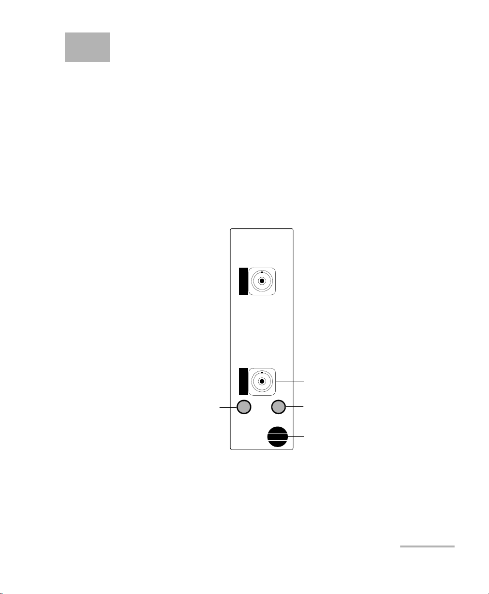
Models and Options
The IQS-3150 module is a high-performance attenuator, part of the IQS
product line.
Input port
Output port
Green LED push button
to start the IQS-3150
software
IQS-3150
Vari abl e
Attenuator
Shutter
Red LED push button to close and
lock, or to open the shutter. When
lit, the shutter is closed.
Retaining screw knob
The module is configured for singlemode or multimode fibers and
complies with optical return loss measurement (ORL) standards on
transmission equipment.
Variable Attenuator 1
Page 8

Introducing the IQS-3150 Variable Attenuator
Models and Options
The IQS-3150 Variable Attenuator is available in four models:
³ Standard singlemode
³ Standard multimode
³ Self-adjusting singlemode (added Output Power contro l m o d e)
³ Self-adjusting multimode (added Output Power control mode)
The self-adjusting modules offer two operation modes: Attenuation
and Power Output. The Attenuation mode allows you to work with a
wide range of attenuation levels. The Output Power mode allows you
to request a fixed output power value and the module automatically
adjusts the attenuation according to that value.
Compatibility with various fiber cores is an option that you can add to your
IQS-3150.
Local and Remote Control
The IQS-3150 Variable Attenuator supports local control (via the
IQS Manager software) and remote control (through GPIB, RS-232, or
Ethernet TCP/IP using SCPI commands or the provided LabVIEW drivers).
For more information, refer to the IQS platform user guide.
Note: With IQS-3100 modules, you can use the LabVIEW drivers created for the
IQS-3150 module. However, the documentation and especially the
examples provided with the drivers are focused on the new functionalities
of the IQS-3150.
2 IQS-3150
Page 9

Introducing the IQS-3150 Variable Attenuator
Typical Applications
Typical Applications
The IQS-3150 Variable Attenuator can be used in a number of test
situations. It is ideal for manufacturing and laboratory applications:
³ Erbium-doped-fiber amplifier (EDFA) and system characterization
³ Component and system loss simulation
³ Optical margin analysis
³ Instrument calibration
³ Power meter linearity measurement
³ Spectral tuning.
The IQS-3150 is perfectly suited for WDM applications by providing the
same attenuation level on all channels simultaneously for a complete
characterization of amplifiers or subsystems.
Variable Attenuator 3
Page 10
Introducing the IQS-3150 Variable Attenuator
Main Software Features
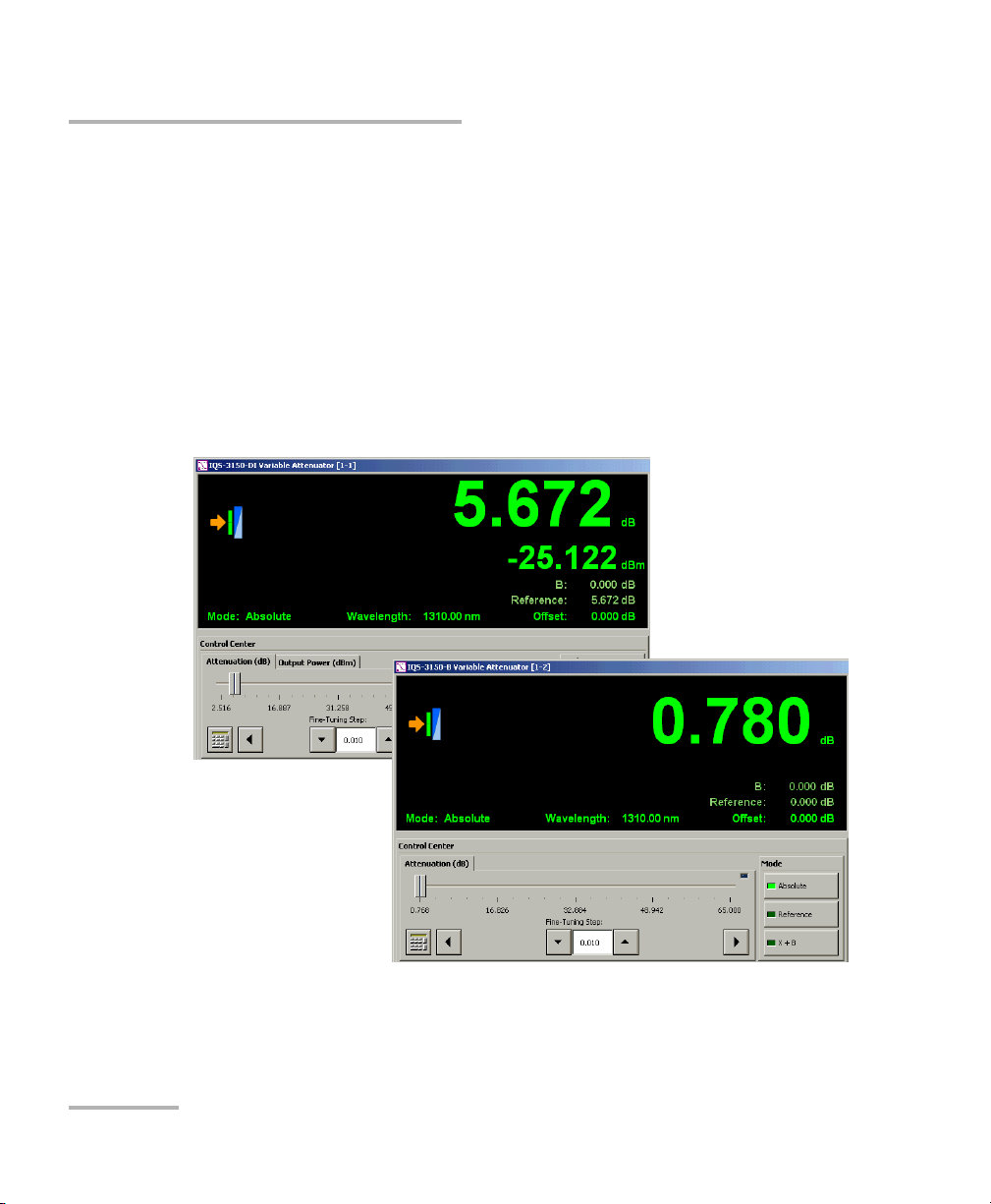
Main Software Features
The dedicated software functions are very similar whether you are using a
self-adjusting or standard module. The following is an overview of the
main features.
Control Center
For the standard module, the output power value does not appear on the
data display and there is no Output Power tab in the Control Center.
Self-adjusting module
Standard module
4 IQS-3150
Page 11

Introducing the IQS-3150 Variable Attenuator
Main Software Features
Control Modes (Self-Adjusting Modules)
With the self-adjusting modules, you can select between two control
modes: Attenuation and Output Power.
Control Mode Description
Attenuation The instrument applies the attenuation values you have selected.
The value appearing at the top of the data display (dB) represents
your attenuation setting whether it was entered in a test sequence or
on the Instrument function tab.
The value appearing underneath the attenuation value is the output
power.
Output Power The instrument produces the output power level you have selected.
The value appearing at the top of the data display (dBm) represents
your power level setting whether it was entered in a test sequence or
on the Instrument function tab.
The value appearing underneath the attenuation value is the output
power.
Variable Attenuator 5
Page 12

Introducing the IQS-3150 Variable Attenuator
Main Software Features
Display Modes
Both standard and self-adjusting modules give you a choice of three
display modes: Absolute, Reference, and X+B.
Attenuation
Display Mode Description
Absolute
(default mode)
The displayed attenuation takes into account both the absolute value
and the offset value.
Displayed att. = absolute att. + offset value
Reference The displayed attenuation value is relative to a defined reference value
(see Selecting a Display Mode on page 30).
Displayed att. = absolute att. – reference value + offset value
X+B The displayed attenuation is the sum of two elements:
³ X = physical attenuation introduced by the unit.
³ B = correction factor (dB). You must define the correction factor
for the test wavelength before enabling the X+B mode (refer to
Setting the B Value on page 23).
Displayed att. = absolute att. + correction factor
³ B = input power value (dBm)
Displayed att. = (absolute att. × –1) + input power
a. The correction factor and the input power value are specific to the wavelength.
a
+ offset value
a
+ offset value
6 IQS-3150
Page 13

Introducing the IQS-3150 Variable Attenuator
Output power
Display Mode Description
Main Software Features
Absolute
(default mode)
The displayed output power takes into account both the absolute
output power value and the offset value.
Displayed power = absolute power + offset value
Reference The displayed output power value is relative to a defined reference
value (see Selecting a Display Mode on page 30).
Displayed power = absolute power – reference value + offset value
X+B The displayed output power is the sum of two elements:
³ X = output power of the unit.
³ B = correction factor. You must define the correction factor for the
test wavelength before enabling the X+B mode (refer to Setting
the B Value on page 23).
Displayed power = absolute power + correction factor
a. The correction factor value is specific to the wavelength.
a
+ offset value
Multiple Module Control
The multimodule application is used to control and monitor several
IQS-3150 variable attenuators at the same time.
Variable Attenuator 7
Page 14

Introducing the IQS-3150 Variable Attenuator
Conventions
Conventions
Before using the product described in this manual, you should understand
the following conventions:
WARNING
Indicates a potentially hazardous situation which, if not avoided,
could result in death or serious injury. Do not proceed unless you
understand and meet the required conditions.
CAUTION
Indicates a potentially hazardous situation which, if not avoided,
may result in minor or moderate injury. Do not proceed unless you
understand and meet the required conditions.
CAUTION
Indicates a potentially hazardous situation which, if not avoided,
may result in component damage. Do not proceed unless you
understand and meet the required conditions.
IMPORTANT
Refers to information about this product you should not overlook.
8 IQS-3150
Page 15

Introducing the IQS-3150 Variable Attenuator
Laser Safety Information
Laser Safety Information
Your IQS-3150 Variable Attenuator does not include laser components in
itself. However, other modules or units you will use may do so. Please,
make sure to follow all laser safety rules.
WARNING
Do not install or terminate fibers while a light source is active.
Never look directly into a live fiber and ensure that your eyes are
protected at all times.
WARNING
Use of controls, adjustments and procedures for operation and
maintenance other than those specified herein may result in
hazardous radiation exposure.
Variable Attenuator 9
Page 16

Page 17
2 Getting Started with Your
Variable Attenuator
Inserting and Removing Test Modules
CAUTION
Never insert or remove a module while the controller unit and its
expansion units are turned on. This will result in immediate and
irreparable damage to both the module and unit.
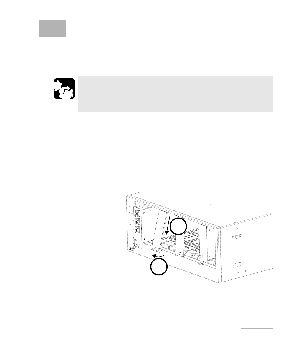
To insert a module into the controller or expansion unit:
1. Exit IQS Manager and turn off all your units.
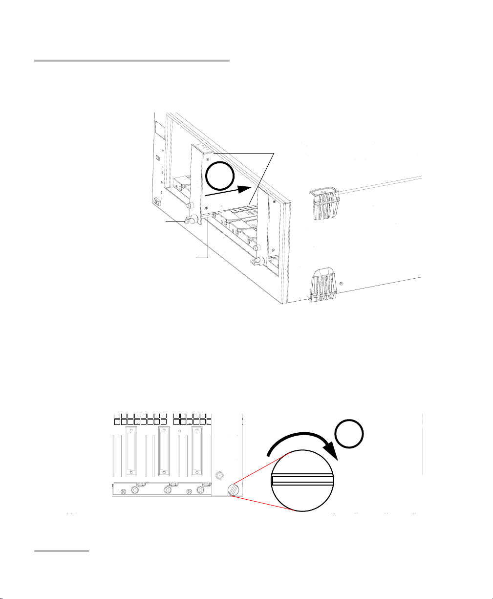
2. Remove the protective cover from the desired unused module slot.
2a. Pull the retaining screw knob firmly towards you and release the
bottom of the cover.
2b. Gently pull the top of the protective cover downwards, to remove
it from the unit grooves.
Protective cover
Retaining screw
knob
2a
3. Position the module so that its front panel is facing you and the top and
bottom protruding edges are to your right.
Variable Attenuator 11
2b
Page 18
Getting Started with Your Variable Attenuator
Inserting and Removing Test Modules
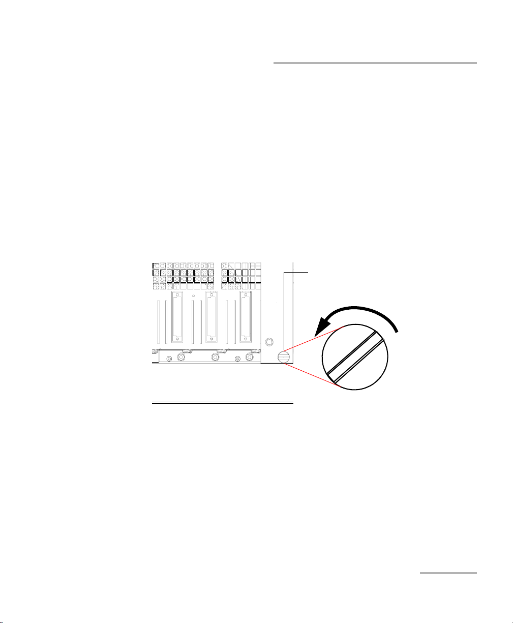
4. Insert the protruding edges of the module into the grooves of the unit’s
module slot.
5
Retaining screw knob
Retaining screw
Protruding edges
(right side of module)
5. Push the module all the way to the back of the slot, until the retaining
screw makes contact with the unit casing.
6. While applying slight pressure to the module, turn the retaining screw
knob (located at the bottom of the panel) clockwise until the knob is
horizontal.
This will secure the module into its “seated” position.
6
12 IQS-3150
Page 19
Getting Started with Your Variable Attenuator
Inserting and Removing Test Modules
The module is correctly inserted when its front panel is flush with the front
panel of the controller or expansion unit.
When you turn on the controller unit, the startup sequence will
automatically detect your module.
Note: You can insert IQ modules into your controller or expansion unit; the
IQS Manager software will recognize them. However, the IQS-3150 locking
mechanism (retaining screw) will not work for IQ modules.
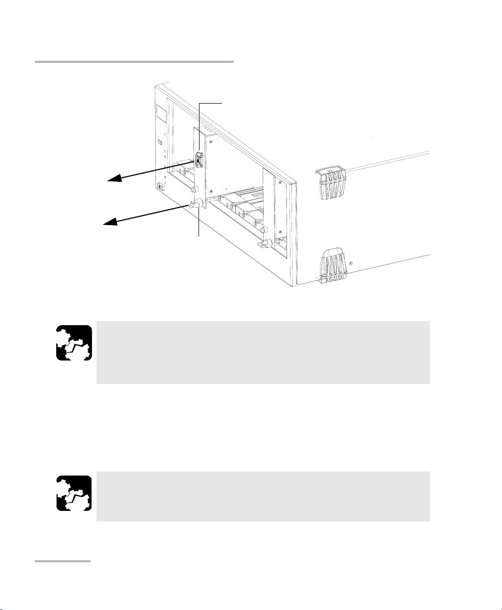
To remove a module from your controller or expansion unit:
1. While pulling gently on the knob, turn it counterclockwise until it stops.
The module will slowly be released from the slot.
Retaining screw knob
2. Place your fingers underneath the module or hold it by the retaining
screw knob (NOT by the connector) and pull it out.
Variable Attenuator 13
Page 20
Getting Started with Your Variable Attenuator
Inserting and Removing Test Modules
Connector
NO
YES
Retaining screw
knob
CAUTION
Pulling out a module by a connector could seriously damage both
the module and connector. Always pull out a module by the
retaining screw knob.
3. Cover empty slots with the supplied protective covers.
3a. Slide the top of the protective cover into the upper grooves of the
unit.
3b. Snap the cover into place by pushing the retaining screw knob.
CAUTION
Failure to reinstall protective covers over empty slots will result in
ventilation problems.
14 IQS-3150
Page 21
Getting Started with Your Variable Attenuator
Starting the Variable Attenuator Application
Starting the Variable Attenuator Application
Your IQS-3150 Variable Attenuator module can be configured and
controlled from its dedicated IQS Manager application.
Note: For details about IQS Manager, refer to the IQS platform user guide.
To start the application:
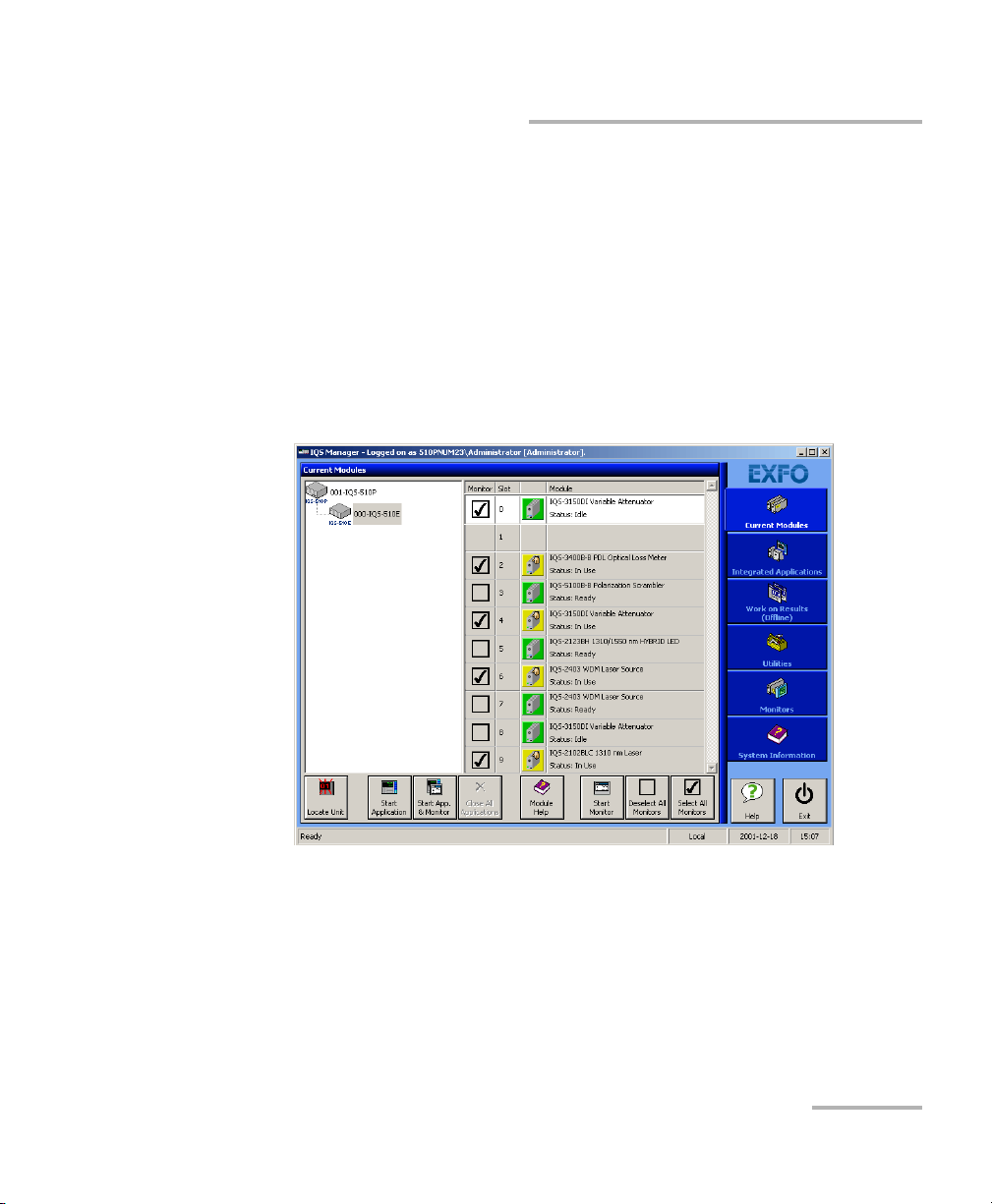
1. From the Current Modules function tab select the module to use.
It will turn white to indicate that it is highlighted.
Note: When starting the application for the first time after a firmware update, it is
possible that the wait period extends over two minutes. Please wait until
the application start is finished before using other commands.
Variable Attenuator 15
Page 22
Getting Started with Your Variable Attenuator
Starting the Variable Attenuator Application
2. Click Start Application.
OR
Press the green LED push button on the front of the corresponding
module.
You can also double-click its row.
Note: Pressing the LED push button will not activate or turn on the module.
Note: To start the corresponding monitor window at the same time, click Start
App. & Monitor. The window opens on the Monitors function tab.
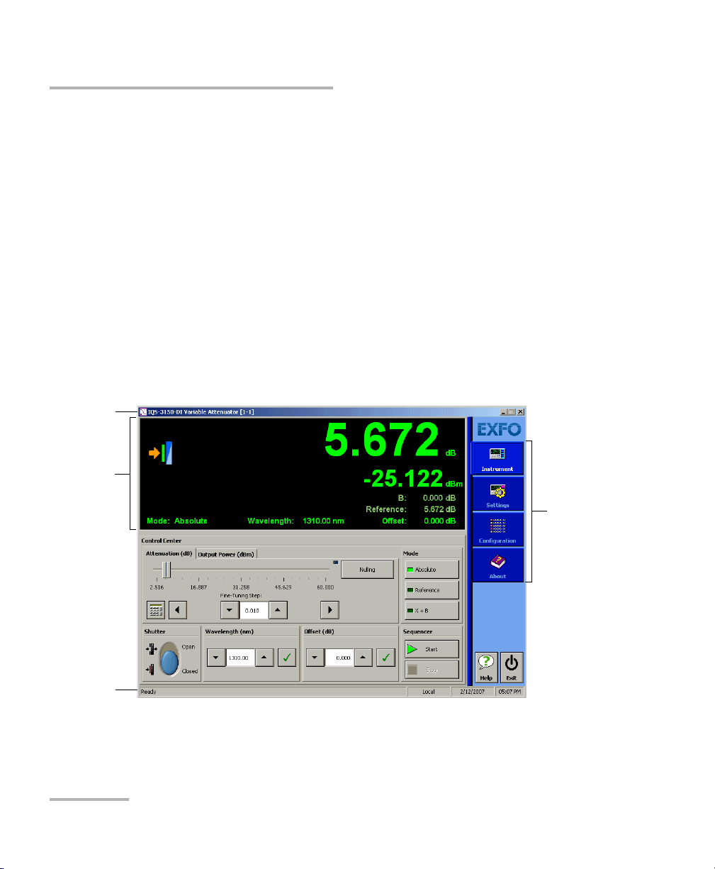
The main window (shown below) contains all the commands required to
control the Variable Attenuator:
Title bar
Data
display
Function
tabs
Status bar
16 IQS-3150
Page 23
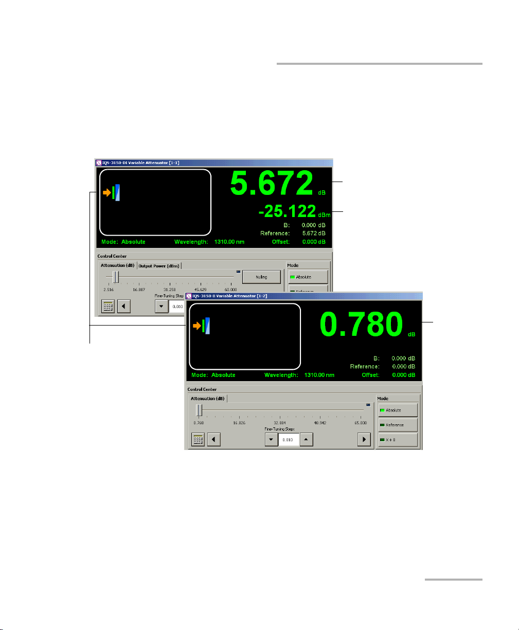
Data Display
Some elements of the data display differ depending on the type of module
you are using (standard or self-adjusting).
Self-adjusting module
Getting Started with Your Variable Attenuator
Starting the Variable Attenuator Application
Current attenuation (Attenuation
control mode) or selected output
power (Output Power control mode)
Output power
Standard module
Current
attenuation
Shutter status and
message area
Variable Attenuator 17
Page 24

Getting Started with Your Variable Attenuator
Starting the Variable Attenuator Application
Title Bar
The title bar is located at the top of the main window. It displays the
module name and its position in the controller or expansion unit. The
module position is identified as follows:
Controller unit or expansion unit (1 to 999) housing
the module
Slot number in which module is inserted
(0 identifies first slot)
[ 999 – 1 ]
Status Bar
The status bar, located at the bottom of the main window, identifies the
operational status of the IQS-3150 Variable Attenuator.
Control mode
Local: Module controlled locally only.
Remote: Module controlled remotely, but
local commands can also be used.
Lockout: Module controlled remotely only.
Current date and timeModule/unit status
For more information about automating or remotely controlling the
IQS-3150 Variable Attenuator, refer to your platform user guide.
18 IQS-3150
Page 25
Getting Started with Your Variable Attenuator
Entering Values Using Sliders and Numeric Boxes
Entering Values Using Sliders and Numeric
Boxes
Many parameters in IQS Manager and module applications can be set
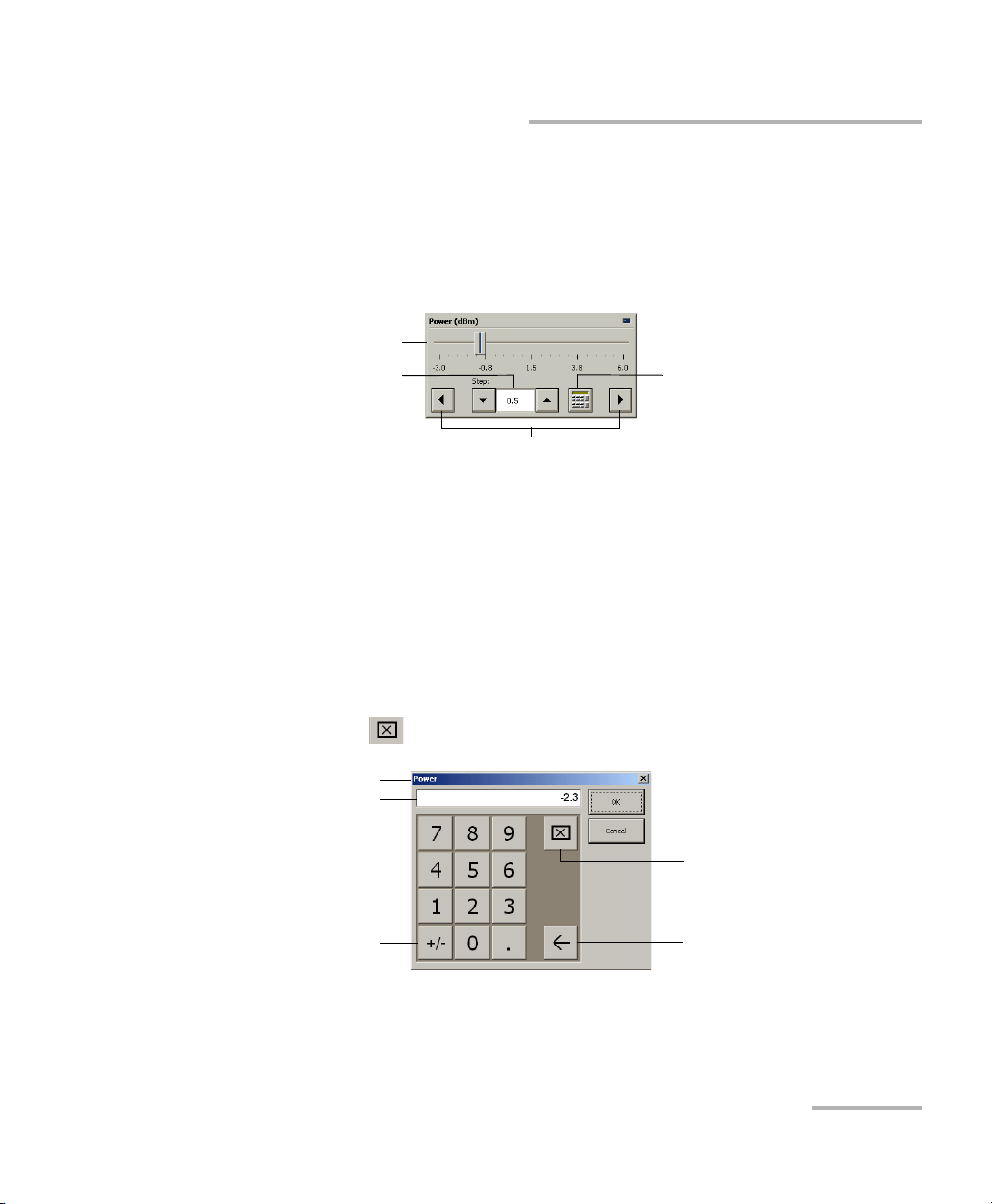
using the following tools.
Slider
Fine-tuning
box
Navigation buttons
³ Slider: Drag it to the desired value on the scale below.
³ Navigation buttons: Click either buttons to move the slider. The slider
moves by steps corresponding to the number in the fine-tuning box,
which you can change by using the up and down arrow buttons next to
the box. You cannot change the list of fine-tuning values from here.
³ Numeric box: Click it to display the on-screen numeric pad, which you
can use to enter a powe value.
Numeric box
button
To enter a value using the numeric box:
1. Use the button to clear the entry display.
Parameter identification
Entry display
Clear button
Toggle button
Backspace button
(to correct a value)
2. Enter the value.
3. Click OK to confirm the value.
Variable Attenuator 19
Page 26

Getting Started with Your Variable Attenuator
Exiting the Application
Exiting the Application
Closing any application that is not currently being used is a good way to
free system memory.
To close the application from the main window:
Click in the top right corner of the main window.
OR
Click the Exit button located at the bottom of the function bar.
To close all currently running applications:
From IQS Manager, click Close All Applications.
20 IQS-3150
Page 27
3 Setting Up Your Variable
Attenuator
The IQS-3150 comes with factory default settings; however, you can create
custom settings and save them in configuration files.
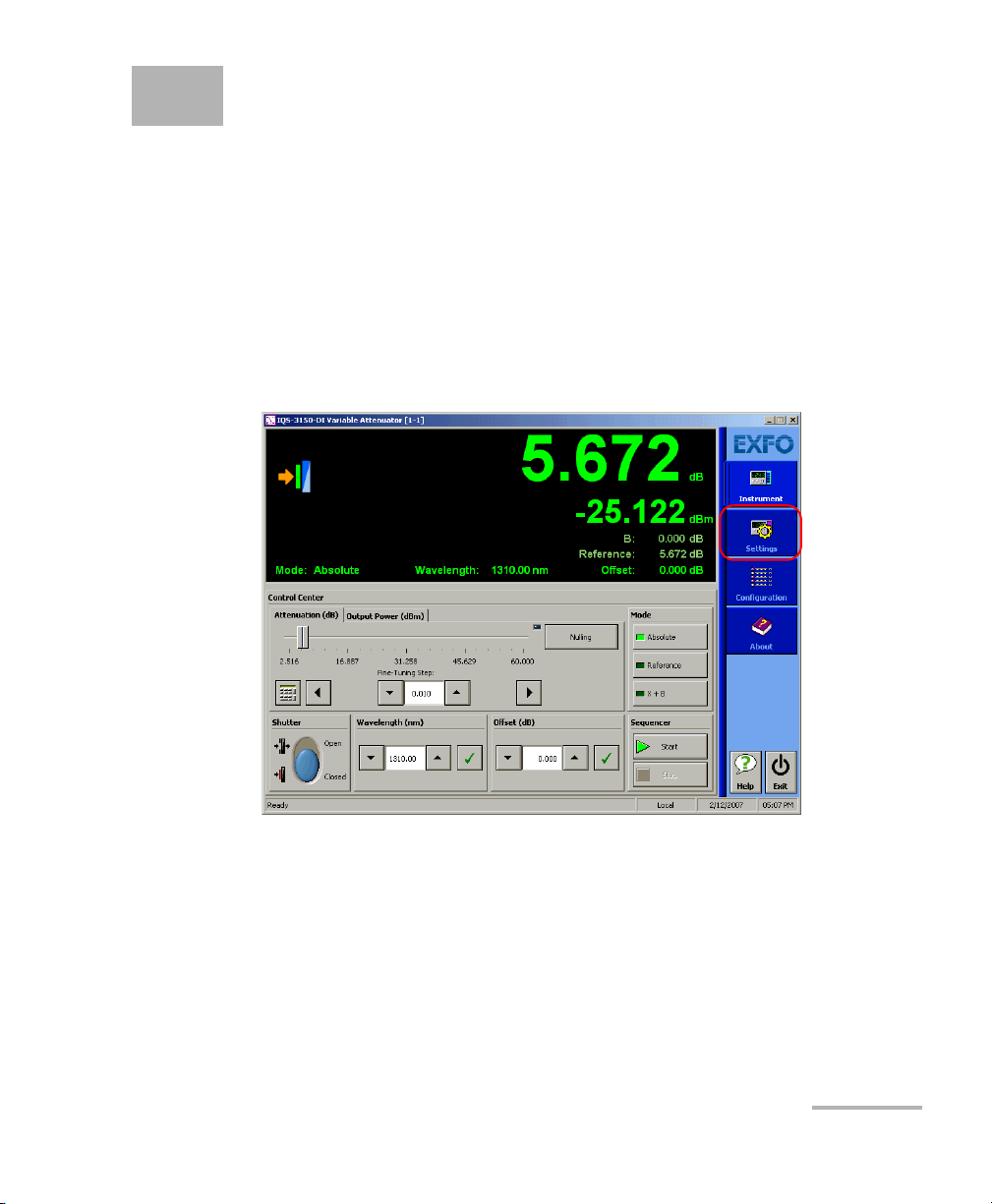
Basic Settings
When you start the Variable Attenuator dedicated application, it opens the
Instrument function tab. To start building your own test settings, click the
Settings function tab.
Variable Attenuator 21
Page 28
Setting Up Your Variable Attenuator
Basic Settings
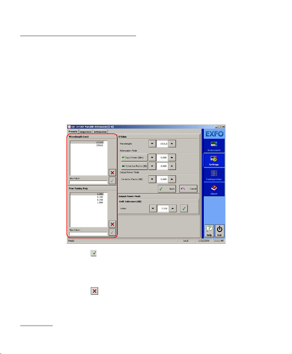
Customizing the Wavelength and Fine-Tuning Step
Lists
You can define lists of wavelengths and fine-tuning steps that will be
available during operation.
To add a value to the lists:
1. On the Settings function tab, click the Presets tab and, under
Waveleng th or Fine-Tuning Step, enter the value in the New Value
box.
2. Click the button to add the value to the list.
To delete a value from the lists:
1. On the Settings function tab, click the Presets tab and, under
Waveleng th or Fine-Tuning Step, click a value in the list to select it.
2. Click the button to delete the value.
22 IQS-3150
Page 29

Setting Up Your Variable Attenuator
Basic Settings
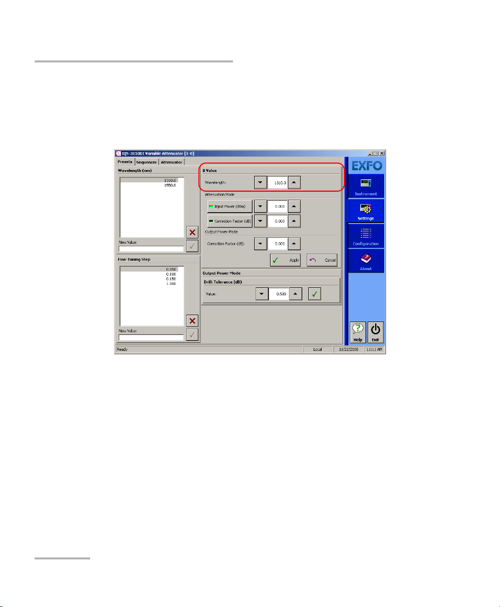
Setting the B Value
The B value settings are necessary for the X+B display mode. These
settings apply to one or many wavelengths defined in the Wa velength list
and are only enabled when using this display mode. The B value settings
are available for both standard and self adjusting modules.
The B value is defined as a correction factor or defined as an input power
value representing the attenuation in the equivalent output power in dBm.
Correction Factor
The Correction factor is available for both Attenuation and Output Power
control modes. This feature can be used to correct a difference in
attenuation or output power from the original specification due to some
changes in the equipment, such as a connector replacement.
Variable Attenuator 23
Page 30
Setting Up Your Variable Attenuator
Basic Settings
To set a correction factor for a wavelength:
1. On the Settings function tab, click the Presets tab.
2. Under BValue, in the Wa velength list, use the up/down arrows to
select the wavelength for which you want to add a correction factor.
24 IQS-3150
Page 31

Setting Up Your Variable Attenuator
Basic Settings
3. According to the control mode used, select the correction factor as
follows:
³ For the Attenuation mode, under Attenuation Mode, click the
Correction Factor button, and enter the correction value in the
box next to it.
³ For the Output power mode, under Output Power Mode, enter the
correction value in the Correction Factor box.
Self-adjusting module
Standard module
4. Click Apply.
Variable Attenuator 25
Page 32

Setting Up Your Variable Attenuator
Basic Settings
Input Power
The Input Power setting, only available in the Attenuation control mode,
allows you to set the source power in dBm. This changes the attenuation
scale values in the Control Center to the equivalent values of the output
power in dBm. You can then use the slider to select an output power value
rather than an attenuation value. It is not as precise as the Output Power
control mode but it is still useful for certain test applications.
To select an input in dBm:
1. On the Settings function tab, click the Presets tab.
2. Under BValue, under Attenuation Mode, click the Input Power
button.
3. In the box next to Input Power, enter the source power in dBm.
4. Click Apply.
26 IQS-3150
Page 33

Setting Up Your Variable Attenuator
Basic Settings
Setting the Drift Tolerance
The drift tolerance setting is only available for the self-adjusting modules
and is only applicable for the Power Tracking function (see Using the
Power Tracking Function (Self-Adjusting Modules) on page 52).
When you use the power tracking function, the internal power meter
monitors the output power level and constantly adjust the attenuation to
ensure that the output power does not exceed the limits set by the user
(drift tolerance). For example, if the power of the source used for the test
drifts over time, the attenuation is adjusted so that the output power
remains within the preset limits.
Requested
power
Output power (dBm)
Time (minutes)
Source power
fluctuation
Drift
tolerance
Power adjusted
by the attenuator
Variable Attenuator 27
Page 34

Setting Up Your Variable Attenuator
Basic Settings
To set the drift tolerance:
1. On the Settings function tab, click the Presets tab.
2. Under Output Power Mode, in the Valu e box, enter the tolerance
value.
3. Click the button to accept the value.
28 IQS-3150
Page 35

Setting Up Your Variable Attenuator
Control Center Settings and Controls
Control Center Settings and Controls
Once the basic settings are entered, you can set parameters in the Control
Center to create your test configuration.
Start creating your configuration by selecting a control mode (self-adjusting
modules only).
Variable Attenuator 29
Page 36

Setting Up Your Variable Attenuator
Control Center Settings and Controls
Selecting a Display Mode
The active display mode determines the significance of the value
appearing on the data display. For a description of each display mode, refer
to Display Modes on page 6.
For the IQS-3150 Variable Attenuator, the absolute (or total)
attenuation is the actual optical insertion loss between the input
and output ports, including connector losses.
Reference
Before clicking the Reference button, select the reference attenuation
or output power (Output Power control mode) value using either the
slider, the left/right arrows, or the numeric box. Upon clicking the
Reference button, the instrument uses the selected attenuation as
reference.
IMPORTANT
Slider
Numeric box
Arrows
X+B
Before clicking the X+B button, make sure that the B value is correctly
set (refer to Setting the B Value on page 23).
30 IQS-3150
Page 37

To select a display mode:
1. Click the Instrument function tab.
The selected
display mode
Setting Up Your Variable Attenuator
Control Center Settings and Controls
2. Under Control Center, enter the appropriate settings.
3. Under Mode click the appropriate button.
The selected display mode appears next to Mode on the data display.
Variable Attenuator 31
Page 38

Setting Up Your Variable Attenuator
Control Center Settings and Controls
Selecting a Wavelength and a Fine-Tuning Step
The attenuator wavelength must be set as closely as possible to the
wavelength of the optical source. The IQS-3150 Variable Attenuator module
provides a wide range of wavelengths: 1250 nm to 1650 nm for singlemode
modules and 700 nm to 1350 nm for multimode modules.
The fine-tuning step can be as low as 0.002.
The lists of available values are built on the Settings tab (refer to
Customizing the Wavelength and Fine-Tuning Step Lists on page 22).
To select a wavelength and a fine-tuning step:
1. Click the Instrument function tab.
2. Under Wa v e l e ngth, use the up/down arrows to select the wavelength,
and click .
3. Under Fine-Tuning Step, use the up/down arrows to select the
fine-tuning value.
32 IQS-3150
Page 39

Setting Up Your Variable Attenuator
Control Center Settings and Controls
Changing the Attenuation or the Output Power
You can change the attenuation or the output power (self-adjusting module
only) value while performing your tests.
In the Attenuation control mode, you can select any value between the
minimum insertion loss and the maximum permitted by the module
specifications. Although EXFO guarantees that the minimum insertion loss
is below a specified value (refer to specification sheet), it may vary slightly
from one wavelength to another and from one IQS-3150 Variable
Attenuator to another.
To change the attenuation or output-power level:
1. Click the Instrument function tab.
2. Click the Attenuation or the Output Power tab.
3. In the Fine-Tuning Step box, enter the step value.
4. Using either the slider, the left/right arrows, or the numeric box, change
the attenuation or output power value.
Variable Attenuator 33
Page 40

Setting Up Your Variable Attenuator
Control Center Settings and Controls
Defining an Offset Value
The offset value is not applied to a particular wavelength. It does not affect
the filter attenuation. It can be used to compensate for the loss generated
elsewhere in the system.
To define an offset value:
1. Click the Instrument function tab.
2. Under Offset, enter de desired value in the box and click to accept
the value.
Note: The offset values must be between -99.999 dB and 99.999 dB. The
attenuation value is positive; therefore, when the offset value is positive,
the displayed attenuation increases.
34 IQS-3150
Page 41

Setting Up Your Variable Attenuator
Creating a Test Sequence
Creating a Test Sequence
The IQS-3150 allows you to create test sequences so that the attenuation or
output power steps are performed automatically without your intervention.
The sequences can be saved and retrieved to be used as is or to be used as
a template in which you can insert or remove steps. To build a new
sequence starting with an old one, under Sequence File, click the Open
button.
To create a completely new sequence, under Sequence File, click the New
button.
IMPORTANT
When you click the New button, all parameters previously set on
the Sequencer tab are erased. Make sure you save the sequence
parameters you want to keep before clicking this button.
A duration can be applied to each step individually, the duration value must
be between 0:00:00 and 999:59:59.
3. You can also set the time at which the sequence will start using one of
the following starting time modes:
³ Absolute: allows you to select a precise time (for example, 10:30:30
am) at which the sequence starts.
³ Relative: allows you to select a countdown between the moment you
start the sequence and the moment it actually starts.
In both modes, you cannot enter a value greater than 23:59:59.
You can also have the sequence repeated for a fixed number of times
(between 1 and 99999) or continuously.
Sequences can be created for both Attenuation and Output Power
(self-adjusting modules) modes.
Variable Attenuator 35
Page 42

Setting Up Your Variable Attenuator
Creating a Test Sequence
Adding, Inserting, and Removing Steps
You can customize test sequences:
³ by adding steps, either to a new sequence or an existing one
³ by inserting steps to an existing sequence.
To add, insert, and remove steps:
1. On the Settings function tab, click the Sequencer tab.
2. Under Sequence Steps, select the control mode.
36 IQS-3150
Page 43

Setting Up Your Variable Attenuator
Creating a Test Sequence
3. In the Attenuation or the Output Power box (depending on the
selected control mode) enter the attenuation or the output power level
you need.
In Attenuation mode In Output Power mode
4. In the Duration box, enter the length of time this level will be applied
before the next step.
5. Click Add (the new step is added at the end of the step list).
OR
Click a step in the Steps list to select it and click Insert (the step is
added before the selected step).
6. To remove a step from the list, click a step in the Steps list to select it
and click Remove.
7. Under Sequence File, click Save As if you want to save that sequence.
Variable Attenuator 37
Page 44

Setting Up Your Variable Attenuator
Creating a Test Sequence
Setting a Starting Time
The start of a test sequence can be set to a definite time of day (Absolute)
or be delayed by a countdown (Relative).
To set a sequence starting time:
1. On the Settings function tab, click the Sequencer tab.
2. Under Sequence File, open a test sequence or create one (refer
to Adding, Inserting, and Removing Steps on page 36).
38 IQS-3150
Page 45

Setting Up Your Variable Attenuator
Creating a Test Sequence
3. Under Starting Time, click the Relative or the Absolute button.
4. In the box below the buttons, enter one of the following value:
³ The amount of time you need between the moment you click the
Start button and the moment the sequence starts (Relative).
³ The time (in the next 24 hours) at which you want the sequence to
start (Absolute).
IMPORTANT
When using the Absolute start time mode, make sure that the clock
of your IQS Platforms is correctly set. The IQS-3150 dedicated
hardware uses that clock setting as time reference.
5. Under Sequence File, click Save As if you want to save that sequence.
Variable Attenuator 39
Page 46

Setting Up Your Variable Attenuator
Creating a Test Sequence
Setting Repetition Scheme
The test sequence can be set to repeat itself for a certain number of times
or on a continuous basis.
Note: If you have entered a setting for the sequence start, the delay or start time
will only apply for the first sequence in the loop.
To set the sequence repetition scheme:
1. On the Settings function tab, click the Sequencer tab.
40 IQS-3150
Page 47

Setting Up Your Variable Attenuator
Creating a Test Sequence
2. Under Sequence File, open a test sequence.
OR
Create a sequence (refer to Adding, Inserting, and Removing Steps on
page 36).
3. Under Sequence Loop, click Loop Count and, in the text box, enter
the number of times the sequence must be repeated.
OR
Click the Continuous Loop button.
4. Under Sequence File, click Save As if you want to save that sequence.
Variable Attenuator 41
Page 48

Setting Up Your Variable Attenuator
Managing Sequence Files
Managing Sequence Files
The commands to open new or existing sequence files and to save them
are located on the Sequencer tab of the Settings function tab.
³ Clicking the New button clears all previous settings allowing you to
build a completely new sequence.
42 IQS-3150
Page 49

Setting Up Your Variable Attenuator
Managing Sequence Files
³ Clicking the Open button opens the Open Sequence File dialog box
from which you can select a sequence file.
³ Clicking the Save As button opens the Save Sequence File dialog box
from which you can select a directory to save your sequence file.
Note: To facilitate the search of sequence files, EXFO recommends that you use
the following elements in the file name: step attenuation or output power
level, step duration, and sequence repetition scheme.
Variable Attenuator 43
Page 50

Setting Up Your Variable Attenuator
Saving and Recalling Configurations
Saving and Recalling Configurations
Once you have set the IQS-3150 Variable Attenuator parameters, you can
save your custom configuration and recall it at any time. You can also recall
the factory-defined settings.
Saved configurations include all parameters set in the Control Center
(Instrument function tab) and in the Settings function tab (if present).
To save a configuration:
1. Select the Configuration function tab.
2. In the Current Module Configuration panel, enter the name you wish
to use for your configuration file.
To always use the last saved
parameters when starting.
To save parameters being used
just before shutting down,
overwriting the previous file.
It will be saved in
D:\IQS Manager\Configuration Files\(your_module)\.
3. Click Save.
44 IQS-3150
Page 51

Setting Up Your Variable Attenuator
Saving and Recalling Configurations
To recall a configuration:
1. Select the Configuration function tab.
2. Click Open.
3. Select the configuration file you wish to recall and confirm your action.
You are returned to the application and the new parameters are set.
To revert to factory settings:
1. Select the Configuration function tab.
2. Click the Reset Module to Factory Settings button.
IMPORTANT
Reverting to the factory settings will interrupt any module
operation in progress.
IMPORTANT
The operation may take a few seconds to complete.
Note: The sequence parameters that you could have set are not part of the data
saved when you click the Save button for the configuration. You must save
your sequence settings by clicking the Save As button under Sequence File
on the Sequencer tab of the Settings function tab. This way your test
configuration and your sequence settings are all saved.
Note: When recalling a saved configuration, the fine-tuning step appearing in the
Control Center reverts to the default value.
Variable Attenuator 45
Page 52

Page 53

4 Operating the IQS-3150
This section presents basic operations using the Variable Attenuator.
Cleaning and Connecting Optical Fibers
IMPORTANT
To ensure maximum power and to avoid erroneous readings:
³ Always clean fiber ends as explained below before inserting
them into the port. EXFO is not responsible for damage or
errors caused by bad fiber cleaning or handling.
³ Ensure that your patchcord has appropriate connectors. Joining
mismatched connectors will damage the ferrules.
To connect the fiber-optic cable to the port:
1. Clean the fiber ends as follows:
1a. Gently wipe the fiber end with a lint-free swab dipped in isopropyl
alcohol.
1b. Use compressed air to dry completely.
1c. Visually inspect the fiber end to ensure its cleanliness.
2. Carefully align the connector and port to prevent the fiber end from
touching the outside of the port or rubbing against other surfaces.
If your connector features a key, ensure that it is fully fitted into the
port’s corresponding notch.
3. Push the connector in so that the fiber-optic cable is firmly in place,
thus ensuring adequate contact.
If your connector features a screwsleeve, tighten the connector
enough to firmly maintain the fiber in place. Do not overtighten, as this
will damage the fiber and the port.
Note: If your fiber-optic cable is not properly aligned and/or connected, you will
notice heavy loss and reflection.
Variable Attenuator 47
Page 54

Operating the IQS-3150
Installing the EXFO Universal Interface (EUI)
Installing the EXFO Universal Interface (EUI)
The EUI fixed baseplate is available for connectors with angled (APC) or
non-angled (UPC) polishing. A green border around the baseplate
indicates that it is for APC-type connectors.
Green border
indicates APC
option
To install an EUI connector adapter onto the EUI baseplate:
1. Hold the EU connector adapter so the dust cap opens downwards.
Bare metal
(or blue border)
indicates UPC
option
2 3 4
2. Close the dust cap in order to hold the connector adapter more firmly.
3. Insert the connector adapter into the baseplate.
4. While pushing firmly, turn the connector adapter clockwise on the
baseplate to lock it in place.
Nulling Electrical Offsets
Temperature and humidity variations affect the performance of electronic
circuits and optical detectors, which can offset measurement results. To
compensate for this offset, the IQS-3150 is equipped with an offset nulling
function.
EXFO recommends performing a nulling of the electrical offsets whenever
environmental conditions change.
48 IQS-3150
Page 55

Operating the IQS-3150
Nulling Electrical Offsets
IMPORTANT
Light must not reach the detector when nulling offsets.
The nulling function is only available for the self-adjusting modules.
To perform the power meter nulling:
1. Click the Instrument function tab.
2. Click the Nulling button.
Variable Attenuator 49
Page 56

Operating the IQS-3150
Running an Attenuation Sequence
Running an Attenuation Sequence
Attenuation sequences allow you to automate and ease your testing
process. Prepare the test sequence as described in Creating a Test
Sequence on page 35.
To start an attenuation sequence:
1. Click the Instrument function tab.
Note: Once a sequence is started, all controls in the Instrument function tab are
disabled to avoid accidental interruptions. However, the monitor and
multimodule applications are not disabled, so you can make changes in
these applications while a sequence is running.
2. Under Sequencer, click the Start button.
The Start button changes to Pause.
50 IQS-3150
Page 57

Operating the IQS-3150
Running an Attenuation Sequence
You can interrupt a sequence at any time by clicking Pause; click Resume
when you are ready to continue.
Note: When you click the Pause button, the sequence will not be restarted at the
point you paused it. Upon clicking the Resume button, the acquisition will
start with the next step in the sequence.
If you click Pause between two steps, when you click Resume the system
will go directly to the next step.
When you have programmed a start time or a start delay, upon clicking the
Start button, a message appears on the data display.
Variable Attenuator 51
Page 58

Operating the IQS-3150
Using the Power Tracking Function (Self-Adjusting Modules)
Using the Power Tracking Function
(Self-Adjusting Modules)
The power tracking function is used to monitor, when in the Output Power
control mode, the output power level and automatically adjust the
attenuation to keep the output power to the requested level.
In order to use the power tracking function, you must define a range of
power levels (see Setting the Drift Tolerance on page 27).
To activate the power tracking function:
From the Instrument function tab, click the Power Tracking button.
52 IQS-3150
Page 59

Operating the IQS-3150
Using the Shutter
Using the Shutter
The shutter is used to let light through the input or block it.
CAUTION
Using the shutter continuously, at a rate of one cycle per three
seconds, may damage the instrument permanently or seriously
reduce its life cycle.
To use the shutter:
1. Click the Instrument function tab.
2. Under Shutter, click the switch to open or close the shutter.
IMPORTANT
Using the Shutter LED push button on the module front panel to
close the shutter disables the software shutter controls. You must
press the push button again to unlock the software controls. The
lock status is indicated by a padlock on the data display.
Variable Attenuator 53
Page 60

Operating the IQS-3150
Using the Shutter
Shutter Status
The status of the shutter is shown on the left of the data display.
It is also shown on the Shutter (red) LED push button on the front panel of
the module; when lit, the shutter is closed.
High-Power Detection
The module is equipped with a sensor that detects the presence of
unusually high power at the input. When high power is detected, the
shutter automatically closes and the high power status is indicated by a
laser-radiation sign on the data display.
Open Close
The red LED push button on the front panel of the module lights up.
54 IQS-3150
Page 61

5 Controlling Multiple Variable
Attenuators
With your platform, you can set common parameters and simultaneously
operate several modules of the same kind in a single interface, which is
particularly useful in larger systems.
Note: You should be familiar with the configuration and operation of a single
module before controlling multiple modules simultaneously.
Starting a Multimodule Application
The multimodule applications available will change according to your
module configuration (model, type, etc.).
Note: When you start a multimodule application, you cannot open a monitor
window at the same time, as it is possible with a single-module
application. You must open the monitor window independently.
To start a multimodule application:
1. In IQS Manager, select the Integrated Applications function tab.
2. Click the appropriate Multiple Module Controller button.
The multimodule application appears in a new window.
Note: More than one Multiple Module Controller button may be displayed if
different models are present in your platform.
Variable Attenuator 55
Page 62

Controlling Multiple Variable Attenuators
Selecting Modules to Control
Selecting Modules to Control
Before you can modify the module parameters, you must specify which
modules you intend to use.
To select IQS-3150 Variable Attenuator modules:
1. On the Modules/Config function tab, select the boxes corresponding
to the modules you want to control.
OR
Click Select All if you want to work with all IQS-3150 Variable
Attenuator modules.
2. Click Apply Selections and click the Instruments function tab.
56 IQS-3150
Page 63

Controlling Multiple Variable Attenuators
Controlling a Single IQS-3150 Variable Attenuator
On the Instruments function tab, you can set parameters for any number
of modules at a time. Select the modules for which you want to set the
parameters and use the functions in the control center. (For more
information on settings and controls, refer to Control Center Settings and
Controls on page 29.)
Controlling a Single IQS-3150 Variable
Attenuator
You may want to control a specific module among all the IQS-3150 Variable
Attenuator modules that you have in the system.
To control a specific IQS-3150 Variable Attenuator:
1. Make sure that the row corresponding to the module you want to
control appears in bold or that it is highlighted.
2. Use the Control Single Instrument button to open the IQS-3150
Variable Attenuator application.
Variable Attenuator 57
Page 64

Controlling Multiple Variable Attenuators
Navigating and Closing Multiple Module Windows
Navigating and Closing Multiple Module
Windows
When controlling multiple modules, a number of windows are open at the
same time. To close a window, use the Exit button located under the
function tabs. You will return to the preceding window.
The following diagram illustrates the navigation between windows:
IQS Manager - Integrated
Open
Applications (Multi-modules)
Apply Selections
Control Single
Instrument
Your modu l e Multiple Module
Controller - Modules/Config tab
Your modu l e Multiple Module
Controller - Instruments tab
Your module main application
window (single module)
Exit
Exit
58 IQS-3150
Page 65

6 Monitoring Variable
Attenuator Modules
When using your IQS-3150 Variable Attenuator module, either alone or with
other modules in a test setup, you can view module data and status using
its monitor window in IQS Manager.
Using Monitor Windows
Monitor windows display basic data about modules. A combination of
resizable windows allows you to create an integrated data display (refer to
the platform user guide).
From the monitor window, you can change module parameters either by:
³ opening the module application to access all the functions
OR
³ using the QuickTools utility, which provides frequently used functions
from the application.
Variable Attenuator 59
Page 66

Monitoring Variable Attenuator Modules
Using Monitor Windows
To select modules and display their monitor windows:
1. On the Current Modules function tab, select the controller or
expansion unit containing the modules you want to monitor.
Selected modules
(checked)
2. In the Monitor column, select the box next to each module you want
to monitor.
If you want to monitor all the modules in the current unit, click Select
All Monitors. If you want to clear your choices, click Deselect All
Monitors.
60 IQS-3150
Page 67

Monitoring Variable Attenuator Modules
Using Monitor Windows
3. Click Start Monitor to apply your selection.
IQS Manager will display the selected monitor windows on the
Monitors function tab.
Note: To start t h e highlighted module’s corresponding application at the same
time, click Start App. & Monitor. The application will appear in a different
window.
Monitor
window
menu
Monitor window
selection buttons
Variable Attenuator 61
Page 68

Monitoring Variable Attenuator Modules
Using QuickTools
Using QuickTools
With QuickTools, you can fine-tune your module directly, while keeping an
eye on your entire test setup.
Note: You can only access QuickTools if the module’s monitor window is selected
from the Monitors function tab and is currently active.
To start QuickTools:
1. From the Monitors function tab, elect the monitor window of the
module you wish to control.
2. Using the arrow button in the upper left corner, select QuickTools.
The corresponding monitor window flashes when QuickTools is
activated.
Note: If you want to open the actual application for your module rather than
QuickTools, click Show Controller.
Attenuation
control mode
For more information on settings and
controls, refer to Control Center Settings
and Controls on page 29.
62 IQS-3150
Output Power
control mode
Page 69

Monitoring Variable Attenuator Modules
Using QuickTools
To c l os e Q u ic k Too ls :
³ Click the Close button located at the top of the window.
OR
³ Click outside the QuickTools window.
To close a monitor window:
Click the button on the upper left of the monitor window and select
Remove Monitor.
OR
Click the Close All button at the bottom of the window.
Variable Attenuator 63
Page 70

Page 71

7 Measuring Multimode
Insertion Loss
Often, when using a multimode source (mostly LED sources), part of the
optical energy is transmitted into the fiber cladding. These cladding modes
attenuate rapidly, but will affect power meter readings if the source is
connected using only a short jumper, as would be the case when taking a
reference before measuring insertion loss.
short distance
long distance
Due to the internal optics of the Variable Attenuator (and the majority of
attenuators), most of the cladding modes are filtered out. This means that,
with the attenuator connected, the power meter will display a loss greater
than the attenuation setting of the attenuator (cladding modes have been
partially stripped).
Cladding modes are not used in communication systems and, therefore,
should not have been part of the source power measurement in the first
place.
Variable Attenuator 65
Page 72

Measuring Multimode Insertion Loss
There are several methods of eliminating these cladding modes:
³ A cladding mode stripper (preferred method) is a material with a
refractive index greater than that of the cladding. With the cladding
exposed, the fiber is immersed in the mode stripper (glycerin, oil, or
other suitable liquid). Due to the greater refractive index of the stripper,
light energy is not reflected at the cladding-stripper interface and
passes through the stripper.
³ Cladding modes attenuate to insignificant levels over relatively short
distances. Therefore, we recommend using a long fiber jumper.
³ A mandrel wrap can be introduced by making a minimum of five turns
around a 0.5 in. diameter mandrel. This method will introduce slight
losses in the multimode core and remove some of the cladding modes.
A mandrel wrap is not the preferred method of controlling cladding
modes in multimode fibers.
66 IQS-3150
Page 73

8 Maintenance
To help ensure long, trouble-free operation:
³ Always clean fiber-optic connectors before using them.
³ Keep the unit free of dust.
³ Clean the unit casing and front panel with a cloth slightly dampened
with water.
³ Store unit at room temperature in a clean and dry area. Keep the unit
out of direct sunlight.
³ Avoid high humidity or significant temperature fluctuations.
³ Avoid unnecessary shocks and vibrations.
³ If any liquids are spilled on or into the unit, turn off the power
immediately and let the unit dry completely.
Use of controls, adjustments, and procedures for operation and
maintenance other than those specified herein may result in
hazardous radiation exposure.
WARNING
Variable Attenuator 67
Page 74

Maintenance
Cleaning Fixed Connectors
Cleaning Fixed Connectors
Regular cleaning of connectors will help maintain optimum performance.
Do not try to disassemble the unit. Doing so would break the connector.
To clean fixed connectors:
1. Fold a lint-free wiping cloth in four to form a square.
2. Moisten the center of the lint-free wiping cloth with only one drop of
isopropyl alcohol.
Alcohol may leave traces if used abundantly. Avoid contact between
the tip of the bottle and the wiping cloth, and do not use bottles
that distribute too much alcohol at a time.
3. Gently wipe the connector threads three times with the folded and
moistened section of the wiping cloth.
IMPORTANT
IMPORTANT
Isopropyl alcohol takes approximately ten seconds to evaporate.
Since isopropyl alcohol is not absolutely pure, evaporation will
leave microscopic residue. Make sure you dry the surfaces before
evaporation occurs.
4. With a dry lint-free wiping cloth, gently wipe the same surfaces three
times with a rotating movement.
5. Throw out the wiping cloths after one use.
68 IQS-3150
Page 75

Maintenance
Cleaning Fixed Connectors
6. Moisten a cleaning tip (2.5 mm tip) with only one drop of isopropyl
alcohol.
IMPORTANT
Alcohol may leave traces if used abundantly. Avoid contact between
the tip of the bottle and the cleaning tip, and do not use bottles
that distribute too much alcohol at a time.
7. Slowly insert the cleaning tip into the connector until it reaches the
ferrule inside (a slow clockwise rotating movement may help).
7
8
9
8. Gently turn the cleaning tip one full turn.
9. Continue to turn as you withdraw the cleaning tip.
10. Repeat steps 7 to 9, but this time with a dry cleaning tip (2.5 mm tip
provided by EXFO).
Note: Make sure you don’t touch the soft end of the cleaning tip and verify the
cleanliness of the cotton tip.
11. Throw out the cleaning tips after one use.
Variable Attenuator 69
Page 76

Maintenance
Cleaning EUI Connectors
Cleaning EUI Connectors
Regular cleaning of EUI connectors will help maintain optimum
performance. There is no need to disassemble the unit.
If any damage occurs to internal connectors, the module casing will
have to be opened and a new calibration will be required.
To clean EUI connectors:
1. Remove the EUI from the instrument to expose the connector
baseplate and ferrule.
IMPORTANT
Turn
Push
2. Moisten a 2.5 mm cleaning tip with one drop of isopropyl alcohol
(alcohol may leave traces if used abundantly).
3. Slowly insert the cleaning tip into the EUI adapter until it comes out on
the other side (a slow clockwise rotating movement may help).
Pull
3
4
5
4. Gently turn the cleaning tip one full turn, then continue to turn as you
withdraw it.
70 IQS-3150
Page 77

Cleaning EUI Connectors
5. Repeat steps 3 to 4 with a dry cleaning tip.
Note: Make sure you don’t touch the soft end of the cleaning tip.
6. Clean the ferrule in the connector port as follows:
6a. Deposit one drop of isopropyl alcohol on a lint-free wiping cloth.
IMPORTANT
Isopropyl alcohol may leave residues if used abundantly or left to
evaporate (about 10 seconds).
Avoid contact between the tip of the bottle and the wiping cloth,
and dry the surface quickly.
6b. Gently wipe the connector and ferrule.
6c. With a dry lint-free wiping cloth, gently wipe the same surfaces to
ensure that the connector and ferrule are perfectly dry.
6d. Verify connector surface with a portable fiber-optic microscope
(for example, EXFO’s FOMS) or inspection probe (for
example, EXFO’s FIP).
Maintenance
WARNING
Verifying the surface of the connector WHILE THE UNIT IS ACTIVE
WILL result in permanent eye damage.
7. Put the EUI back onto the instrument (push and turn clockwise).
8. Throw out cleaning tips and wiping cloths after one use.
Variable Attenuator 71
Page 78

Maintenance
Cleaning Detector Ports
Cleaning Detector Ports
Regular cleaning of detectors will help maintain measurement accuracy.
Always cover detectors with protective caps when unit is not in use.
To clean detector ports:
1. Remove the protective cap and adapter (FOA) from the detector.
2. If the detector is dusty, blow dry with compressed air.
3. Being careful not to touch the soft end of the swab, moisten a cleaning
tip with only one drop of isopropyl alcohol.
Alcohol may leave traces if used abundantly. Do not use bottles that
distribute too much alcohol at a time.
IMPORTANT
IMPORTANT
4. While applying light pressure (to avoid breaking the detector window),
gently rotate the cleaning tip on the detector window.
5. Repeat step 4 with a dry cleaning tip or blow dry with compressed air.
6. Discard the cleaning tips after one use.
72 IQS-3150
Page 79

Maintenance
Homing the Variable Attenuator (User Calibration)
Homing the Variable Attenuator (User
Calibration)
The variable attenuator contains mechanical elements used to change
attenuation or output power (self-adjusting modules) levels. It is a good
practice to have the instrument mechanism return to the zero (home)
position to reestablish its relative position on the range of attenuation or
output power levels.
EXFO recommends that you perform the homing procedure when the
homing icon appears on the data display.
To home the attenuator:
1. On the Settings function tab, click the Attenuator tab.
2. Click the User Calibration button.
The attenuator mechanism is moved to the zero (home) position.
Variable Attenuator 73
Page 80

Maintenance
Recalibrating the Unit
Recalibrating the Unit
Manufacturing and service center calibrations are based on the
ISO/IEC 17025 Standard, which states that calibration documents must not
contain a recommended calibration interval, unless this has been
previously agreed upon with the customer.
Validity of specifications depends on operating conditions. For example,
the calibration validity period can be longer or shorter depending on the
intensity of use, environmental conditions and unit maintenance. You
should determine the adequate calibration interval for your unit according
to your accuracy requirements.
Under normal use, EXFO recommends calibrating your unit every year.
74 IQS-3150
Page 81

Maintenance
Recycling and Disposal (Applies to European Union Only)
Recycling and Disposal
(Applies to European Union Only)
Recycle or dispose of your product (including electric and
electronic accessories) properly, in accordance with local
regulations. Do not dispose of it in ordinary garbage receptacles.
This equipment was sold after August 13, 2005 (as identified by
the black rectangle).
³ Unless otherwise noted in a separate agreement between EXFO and a
customer, distributor or commercial partner, EXFO will cover costs
related to the collection, treatment, recovery and disposal of
end-of-lifecycle waste generated by electronic equipment introduced
after August 13, 2005 to an European Union member state with
legislation regarding Directive 2002/96/EC.
³ Except for reasons of safety or environmental benefit, equipment
manufactured by EXFO, under its brand name, is generally designed to
facilitate dismantling and reclamation.
For complete recycling/disposal procedures and contact information, visit
the EXFO Web site at www.exfo.com/recycle.
Variable Attenuator 75
Page 82

Page 83

9 Troubleshooting
Viewing Online Documentation
An online version of the IQS-3150 Variable Attenuator user guide is
conveniently available at all times from the application.
To access the online user guide:
Click Help in the function bar.
Finding Information on the EXFO Web Site
The EXFO Web site provides answers to frequently asked questions (FAQs)
regarding the use of your IQS-3150 Variable Attenuator.
To a c c e ss F A Qs :
1. Ty pe http://www.exfo.com in your Internet browser.
2. Click the Support tab.
3. Click FAQs and follow the on-screen instructions. You will be given a
list of questions pertaining to your subject.
The EXFO Web site also provides the product’s most recent technical
specifications.
Variable Attenuator 77
Page 84

Troubleshooting
Contacting the Technical Support Group
Contacting the Technical Support Group
To obtain after-sales service or technical support for this product, contact
EXFO at one of the following numbers. The Technical Support Group is
available to take your calls from Monday to Friday, 8:00 a.m. to 7:00 p.m.
(Eastern Time in North America).
For detailed information about technical support, visit the EXFO Web site at
www.exfo.com.
Technical Support Group
400 Godin Avenue
Quebec (Quebec) G1M 2K2
CANADA
To accelerate the process, please have information such as the name and
the serial number (see the product identification label—an example is
shown below), as well as a description of your problem, close at hand.
1 866 683-0155 (USA and Canada)
Tel.: 1 418 683-5498
Fax: 1 418 683-9224
support@exfo.com
P/N
**************** A
542392-3D
S/N
Made in Canada QST442B
January 2020
Ver.
Mfg.
date
465 Godin Avenue
Vanier (Quebec) G1M 3G7 CANADA
IQS-3150-X XX
Option
Connector code
78 IQS-3150
Page 85

Troubleshooting
Contacting the Technical Support Group
You may also be requested to provide software and module version
numbers. This information, as well as technical support contact
information, can be found in the About function tab.
³ Select the Technical Support tab to view phone numbers and active
Internet links to EXFO’s Technical Support Group. Use these links to
send an information request by email or to access EXFO’s web site.
³ Select the Module Information tab to view the module identification,
serial number and firmware version.
Variable Attenuator 79
Page 86

Troubleshooting
Transportation
Transportation
Maintain a temperature range within specifications when transporting the
unit. Transportation damage can occur from improper handling. The
following steps are recommended to minimize the possibility of damage:
³ Pack the unit in its original packing material when shipping.
³ Avoid high humidity or large temperature fluctuations.
³ Keep the unit out of direct sunlight.
³ Avoid unnecessary shocks and vibrations.
80 IQS-3150
Page 87

10 Warranty
General Information
EXFO Electro-Optical Engineering Inc. (EXFO) warrants this equipment
against defects in material and workmanship for a period of two years from
the date of original shipment. EXFO also warrants that this equipment will
meet applicable specifications under normal use.
During the warranty period, EXFO will, at its discretion, repair, replace,
or issue credit for any defective product, as well as verify and adjust the
product free of charge should the equipment need to be repaired or if the
original calibration is erroneous. If the equipment is sent back for
verification of calibration during the warranty period and found to meet all
published specifications, EXFO will charge standard calibration fees.
THIS WARRANTY IS IN LIEU OF ALL OTHER WARRANTIES EXPRESSED,
IMPLIED, OR STATUTORY, INCLUDING, BUT NOT LIMITED TO, THE
IMPLIED WARRANTIES OF MERCHANTABILITY AND FITNESS FOR A
PARTICULAR PURPOSE. IN NO EVENT SHALL EXFO BE LIABLE FOR
SPECIAL, INCIDENTAL, OR CONSEQUENTIAL DAMAGES.
Liability
EXFO shall not be liable for damages resulting from the use of the product,
nor shall be responsible for any failure in the performance of other items to
which the product is connected or the operation of any system of which
the product may be a part.
EXFO shall not be liable for damages resulting from improper usage or
unauthorized modification of the product, its accompanying accessories
and software.
Variable Attenuator 81
Page 88

Warranty
Exclusions
Exclusions
EXFO reserves the right to make changes in the design or construction of
any of its products at any time without incurring obligation to make any
changes whatsoever on units purchased. Accessories, including but not
limited to fuses, pilot lamps, batteries and universal interfaces (EUI) used
with EXFO products are not covered by this warranty.
This warranty excludes failure resulting from: improper use or installation,
normal wear and tear, accident, abuse, neglect, fire, water, lightning or
other acts of nature, causes external to the product or other factors beyond
EXFO’s control.
Certification
EXFO certifies that this equipment met its published specifications at the
time of shipment from the factory.
82 IQS-3150
Page 89

Warranty
Service and Repairs
Service and Repairs
EXFO commits to providing product service and repair for five years
following the date of purchase.
To send any equipment for service or repair:
1. Call one of EXFO’s authorized service centers (see EXFO Service
Centers Worldwide on page 84). Support personnel will determine if
the equipment requires service, repair, or calibration.
2. If equipment must be returned to EXFO or an authorized service
center, support personnel will issue a Return Merchandise
Authorization (RMA) number and provide an address for return.
3. If possible, back up your data before sending the unit for repair.
4. Pack the equipment in its original shipping material. Be sure to include
a statement or report fully detailing the defect and the conditions under
which it was observed.
5. Return the equipment, prepaid, to the address given to you by support
personnel. Be sure to write the RMA number on the shipping slip. EXFO
will refuse and return any package that does not bear an RMAnumber.
Note: A test setup fee will apply to any returned unit that, after test, is found to
meet the applicable specifications.
After repair, the equipment will be returned with a repair report. If the
equipment is not under warranty, you will be invoiced for the cost
appearing on this report. EXFO will pay return-to-customer shipping costs
for equipment under warranty. Shipping insurance is at your expense.
Routine recalibration is not included in any of the warranty plans. Since
calibrations/verifications are not covered by the basic or extended
warranties, you may elect to purchase FlexCare Calibration/Verification
Packages for a definite period of time. Contact an authorized service center
(see EXFO Service Centers Worldwide on page 84).
Variable Attenuator 83
Page 90

Warranty
EXFO Service Centers Worldwide
EXFO Service Centers Worldwide
If your product requires servicing, contact your nearest authorized service
center.
EXFO Headquarters Service Center
400 Godin Avenue
Quebec (Quebec) G1M 2K2
CANADA
EXFO Europe Service Center
Omega Enterprise Park, Electron Way
Chandlers Ford, Hampshire S053 4SE
ENGLAND
EXFO China Service Center/
Beijing OSIC
Beijing New Century Hotel
Office Tower, Room 1754-1755
No. 6 Southern Capital Gym Road
Beijing 100044
P. R . C H I N A
1 866 683-0155 (USA and Canada)
Tel.: 1 418 683-5498
Fax: 1 418 683-9224
quebec.service@exfo.com
Tel.: +44 2380 246810
Fax: +44 2380 246801
europe.service@exfo.com
Tel.: +86 (10) 6849 2738
Fax: +86 (10) 6849 2662
beijing.service@exfo.com
84 IQS-3150
Page 91

A Technical Specifications
SPECIFICATIONS
a
Singlemode Configurations
Description Without power monitoring With power monitoring
Models IQS-3150-B IQS-3150-BI
Fiber type (μm) 9/125 9/125
Wavelength range (nm) 1250 to 1650 1250 to 1650
Max. attenuationb(dB) ≥ 65 ≥ 65
Insertion loss
c,d
(dB)
Typical 1.0 1.5
Max. 1.5 2.2
Attenuation setting resolution (dB), typical 0.002 0.002
Attenuation linearitye(dB) ±0.1 ±0.1
Attenuation repeatabilityf(dB), 2σ ±0.01 ±0.01
Spectral uniformity, 1510 nm to 1605 nmg(dB) ±0.05 ±0.05
Spectral uniformity, 1450 nm to 1630 nmg(dB), typical ±0.09 ±0.0 9
Power meter linearityh(dB) N/A ±0.03
Power setting repeatability (dB), 2σ N/A ±0.015
PDLi(dB) peak-to-peak 0.15 0.2
Return loss
c, j
(dB), typical 60 60
Max. input power (dBm) 23 23
Transition speedk(dB/s), typical ≥ 15 ≥ 15
Shutter isolation (dB) > 100 > 100
Multimode Configurations
Description Without power monitoring With power monitoring
Models IQS-3150-C; D IQS-3150-CI; DI
Fiber type (μm) 50/125, 62.5/125 50/125, 62.5/125
Wavelength range (nm) 700 to 1350 700 to 1350
Max. attenuation (dB) ≥ 60 ≥ 60
Insertion loss
c,d
(dB)
Typical 1.3 1.5
Max. 2.0 3.0
Attenuation setting resolution (dB), typical 0.002 0.002
Attenuation linearitye(dB) ±0.1 ±0.1
Attenuation repeatabilityf(dB), 2σ ±0.01 ±0.01
Power meter linearityl(dB) N/A ±0.03
Power setting repeatability (dB), 2σ N/A ±0.015
Return loss
c, d
(dB), typical 40 40
Max. input power (dBm) 20 20
Transition speedk(dB/s), typical ≥ 15 ≥ 15
Shutter isolation (dB), typical > 90 > 90
IMPORTANT
The following technical specifications can change without notice.
The information presented in this section is provided as a reference
only. To obtain this product’s most recent technical specifications,
visit the EXFO Web site at www.exfo.com.
Variable Attenuator 85
Page 92

Technical Specifications
GENERAL SPECIFICATIONS
Size (H X W X D) 125 mm X 36 mm X 282 mm (4 15/16in X 1 7/16in X 11 1/8in)
Weight 0.7 kg (1.6 lb)
Temperature
Operating 0 °C to 40 °C (32 °F to 122 °F)
Storage –40 °C to 70 °C (–40 °F to 158 °F)
Relative humidity 0 % to 80 % non-condensing
86 IQS-3150
Page 93

B SCPI Command Reference
This appendix presents detailed information on the commands and
queries supplied with your IQS-3150 Variable Attenuator.
IMPORTANT
Since the IQS controllers and expansion units can house many
instruments, you must explicitly specify which instrument you want
to remotely control.
You must add the following mnemonic at the beginning of any
command or query that you send to an instrument (except for
IEEE 488.2 and platform commands):
LINStrument<LogicalInstrumentPos>:
where <LogicalInstrumentPos> corresponds to the identification
number of the instrument.
IQS controller or expansion unit
identification number (for example, 001)
XXXY
Instrument slot number (0 to 9)
For information on modifying unit identification, refer to your
platform user guide.
Variable Attenuator 87
Page 94

SCPI Command Reference
Quick Reference Command Tree
Quick Reference Command Tree
Command Param eter (s) P.
CALibration
[1..n]
CONTrol[1..n] MODE ATTenuation|POWer 91
INPut[1..n] ARESolution? 93
OUTPut[1..n] ALC [STATe] <State> 115
ZERO 90
MODE? 92
ATTen uat ion <Attenuation[<wsp>DB]>|
ATTen uat ion ? [MAXimum|MINimum|DEFault] 96
OFFSet <Offset[<wsp>DB]>|MAXimum|
OFFSet? [MAXimum|MINimum|DEFault] 100
RATTenuation <RelativeAttenuation[<wsp>DB]>
RATTenuation? [MAXimum|MINimum|DEFault] 105
REFerence <Reference[<wsp>DB]>
REFerence? [MAXimum|MINimum|DEFault] 109
WAVel engt h <Wavelength[<wsp>M]>
WAVel engt h? [MAXimum|MINimum|DEFault] 113
[STATe]? 116
APMode ABSolute|XB|REFerence 117
APMode? 119
DTOlerance <Drift[<wsp>DB]>|MAXimum|
DTOlerance? [MAXimum|MINimum|DEFault] 122
LOCK [STATe]? 124
OFFSet <Offset[<wsp>DB]>|MAXimum|
OFFSet? [MAXimum|MINimum|DEFault] 127
POWer <Power[<wsp>DBM]>|MAXimum
POWer? [MAXimum|MINimum|DEFault] 131
MAXimum|MINimum|DEFault
MINimum|DEFault
|MAXimum|MINimum|DEFault
|MAXimum|MINimum|DEFault
|MAXimum|MINimum|DEFault
MINimum|DEFault
MINimum|DEFault
|MINimum|DEFault
94
98
102
107
111
120
125
129
88 IQS-3150
Page 95

SCPI Command Reference
Quick Reference Command Tree
Command Param eter (s) P.
REFerence <Reference[<wsp>DBM]>
REFerence? [MAXimum|MINimum|DEFault] 135
RPOWer <RelativePower[<wsp>DBM]>
RPOWer? [MAXimum|MINimum|DEFault] 139
[STATe] <ShutterState> 141
[STATe]? 142
READ[1..n] [SCALar] POWer DC? 143
SENSe[1..n] CORRection COLLect ZERO 144
SNUMber? 145
STATus? 146
STATus OPERation BIT<n> CONDition? 147
QUEStionable BIT<n> CONDition? 149
|MAXimum|MINimum|DEFault
|MAXimum|MINimum|DEFault
133
137
Variable Attenuator 89
Page 96

SCPI Command Reference
Product-Specific Commands—Description
Product-Specific Commands—Description
Description Returns the mechanism of the instrument to its
Syntax :CALibration[1..n]:ZERO
Parameter(s) None
Example(s) STAT:QUES:BIT9:COND? Returns 1 if the
:CALibration[1..n]:ZERO
home position.
This command is an event and has no associated
*RST condition or query form.
instrument's mechanism should be returned to
its home position.
STAT? Must return READY
CAL:ZERO
STAT:OPER:BIT9:COND? Keep resending the
query as long as the operation is not complete
(returned value is not 0).
Notes This command will take at least 15 seconds to
complete.
See Also :SENSe[1..n]:CORRection:COLLect:ZERO
:STATus:OPERation:BIT<n>:CONDition?
:STATus:QUEStionable:BIT<n>:CONDition?
90 IQS-3150
Page 97

SCPI Command Reference
Product-Specific Commands—Description
:CONTrol[1..n]:MODE
Description This command selects the attenuator's control
mode.
At *RST, the control mode is ATTenuation.
Syntax :CONTrol[1..n]:MODE<wsp>ATTenuation|
POWer
Parameter(s) Parameter 1:
The program data syntax for the first parameter is
defined as a <CHARACTER PROGRAM DATA>
element. The allowed <CHARACTER PROGRAM
DATA> elements for this parameter are:
ATTenuation|POWer.
This parameter represents the newly selected
control mode.
ATTenuation: selects the attenuation control
mode.
POWer:selects the power control mode.
Example(s) CONT:MODE POW
CONT:MODE ATTENUATION
See Also :CONTrol[1..n]:MODE?
:INPut[1..n]:ATTenuation
:INPut[1..n]:RATTenuation
:OUTPut[1..n]:POWer
:OUTPut[1..n]:RPOWer
Variable Attenuator 91
Page 98

SCPI Command Reference
Product-Specific Commands—Description
Description This query returns the attenuator's control mode.
Syntax :CONTrol[1..n]:MODE?
Parameter(s) None
Response Syntax <Mode>
Response(s) Mode:
:CONTrol[1..n]:MODE?
At *RST, the control mode is ATTenuation.
The response data syntax for <Mode> is defined
as a <CHARACTER RESPONSE DATA> element.
The <Mode> response corresponds to the
selected control mode.
ATTENUATION: the attenuation control mode is
selected.
POWER: the power control mode is selected.
Example(s) CONT:MODE POW
CONT:MODE? Returns POWER
See Also :CONTrol[1..n]:MODE
:INPut[1..n]:ATTenuation
:INPut[1..n]:RATTenuation
:OUTPut[1..n]:POWer
:OUTPut[1..n]:RPOWer
92 IQS-3150
Page 99

SCPI Command Reference
Product-Specific Commands—Description
:INPut[1..n]:ARESolution?
Description This query returns the smallest attenuation step
available. Use this command to determine the
maximum resolution of the attenuation.
*RST has no effect on this command.
Syntax :INPut[1..n]:ARESolution?
Parameter(s) None
Response Syntax <Resolution>
Response(s) Resolution:
The response data syntax for <Resolution> is
defined as a <NR3 NUMERIC RESPONSE DATA>
element.
The <Resolution> response represents the
smallest attenuation step available.
Example(s) INP:ARES? Returns: 2.000000E–003
Variable Attenuator 93
Page 100

SCPI Command Reference
Product-Specific Commands—Description
Description This command sets the absolute attenuation to a
Syntax :INPut[1..n]:ATTenuation<wsp><Attenuation[<
:INPut[1..n]:ATTenuation
specific value. The valid range of values depends
on the type of instrument and the current
wavelength. This value is used only when the
ATTenuation control mode is active.
In POWer mode, the device adjusts the
attenuation automatically to match the desired
output power. For this reason, changes made to
attenuation via the INPut[1..n]:ATT command are
not taken into account.
At *RST, the absolute attenuation value that will
be set depends on the instrument you have.
wsp>DB]>|MAXimum|MINimum|DEFault
Parameter(s) Attenuation:
The program data syntax for <Attenuation> is
defined as a <numeric_value> element
followed by an optional <SUFFIX PROGRAM
DATA> element. The allowed <SUFFIX
PROGRAM DATA> element is DB. The
<Attenuation> special forms MINimum,
MAXimum and DEFault are accepted on input.
MINimum allows to set the instrument to the
smallest supported value.
MAXimum allows to set the instrument to the
highest supported value.
94 IQS-3150
 Loading...