

Page 1
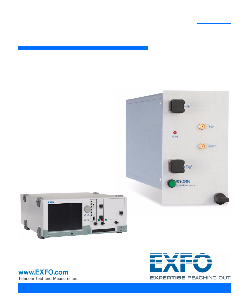
IQS-2600B
Tunable Laser Source for IQS Platforms
User Guide
Page 2

Copyright © 2003–2011 EXFO Inc. All rights reserved. No part of this
publication may be reproduced, stored in a retrieval system or transmitted
in any form, be it electronically, mechanically, or by any other means such
as photocopying, recording or otherwise, without the prior written
permission of EXFO Inc. (EXFO).
Information provided by EXFO is believed to be accurate and reliable.
However, no responsibility is assumed by EXFO for its use nor for any
infringements of patents or other rights of third parties that may result from
its use. No license is granted by implication or otherwise under any patent
rights of EXFO.
EXFO’s Commerce And Government Entities (CAGE) code under the North
Atlantic Treaty Organization (NATO) is 0L8C3.
The information contained in this publication is subject to change without
notice.
Trademarks
EXFO’s trademarks have been identified as such. However, the presence
or absence of such identification does not affect the legal status of any
trademark.
Units of Measurement
Units of measurement in this publication conform to SI standards and
practices.
Version number: 3.0.1
ii IQS-2600B
Page 3

Contents
Contents
Certification Information ........................................................................................................v
1 Introducing the IQS-2600B Tunable Laser Source ...................................... 1
General Information ...............................................................................................................1
Typical Applications ................................................................................................................2
IQS-2600CT Tunable Laser Source for IQS-12004B DWDM Passive Component Test System ...3
Conventions ............................................................................................................................4
2 Safety Information ....................................................................................... 5
3 Getting Started with Your Tunable Laser Source ....................................... 7
Inserting and Removing Test Modules ....................................................................................7
Starting the Tunable Laser Source Application ......................................................................11
Entering Values Using Sliders and Numeric Boxes .................................................................14
Exiting the Application .........................................................................................................15
4 Setting Standard Parameters .................................................................... 17
Switching between Normal and High-Resolution (HR) Modes ..............................................18
Selecting the Display Unit .....................................................................................................19
Selecting a Wavelength ........................................................................................................20
Setting the Power .................................................................................................................22
Adding Items to Lists ............................................................................................................24
Deleting Items from Lists ......................................................................................................25
Saving and Recalling Configurations .....................................................................................26
5 Setting Sweep Parameters ........................................................................ 29
Setting the Start and End Wavelengths ................................................................................29
Setting a Delay for the Sweep ...............................................................................................30
Selecting the Sweep Mode ...................................................................................................30
Selecting the Incoming Trigger Option .................................................................................32
Setting the Cycle Options .....................................................................................................33
Setting the Sweep Direction .................................................................................................34
6 Operating your Tunable Laser Source ....................................................... 35
Cleaning and Connecting Optical Fibers ...............................................................................35
Installing the EXFO Universal Interface (EUI) .........................................................................37
Activating/Deactivating Light Emission .................................................................................38
Starting a Sweep ..................................................................................................................39
Tunable Laser Source iii
Page 4

Contents
7 Monitoring Your Tunable Laser Source .....................................................41
Using Monitor Windows .......................................................................................................41
Using QuickTools ...................................................................................................................44
8 Maintenance ................................................................................................47
Cleaning Fixed Connectors ....................................................................................................48
Cleaning EUI Connectors ......................................................................................................50
Adjusting Your Unit According to Wavelength .....................................................................52
Recalibrating the Unit ...........................................................................................................54
Recycling and Disposal (Applies to European Union Only) ....................................................54
9 Troubleshooting ..........................................................................................55
Solving Common Problems ...................................................................................................55
Viewing Online Documentation ............................................................................................56
Contacting the Technical Support Group ..............................................................................57
Transportation ......................................................................................................................59
10 Warranty ......................................................................................................61
General Information .............................................................................................................61
Liability .................................................................................................................................61
Exclusions .............................................................................................................................62
Certification ..........................................................................................................................62
Service and Repairs ...............................................................................................................63
EXFO Service Centers Worldwide ..........................................................................................64
A Technical Specifications ..............................................................................65
B SCPI Command Reference ..........................................................................69
Quick Reference Command Tree ...........................................................................................70
Product-Specific Commands—Description ............................................................................72
C Trigger Option Theory ..............................................................................129
Trigger Option in Continuous Mode ...................................................................................129
Trigger Option in Stepped Mode ........................................................................................130
Index ...............................................................................................................131
iv IQS-2600B
Page 5

Certification Information
Certification Information
FCC Information
Electronic test equipment is exempt from Part 15 compliance (FCC) in
the United States. However, compliance verification tests are
systematically performed on most EXFO equipment.
Information
Electronic test equipment is subject to the EMC Directive in the European
Union. The IEC 61326-1 standard prescribes both emission and immunity
requirements for laboratory, measurement, and control equipment.
This unit has undergone extensive testing according to the European Union
Directive and Standards.
IMPORTANT
Use of shielded remote I/O cables, with properly grounded shields
and metal connectors, is recommended in order to reduce radio
frequency interference that may emanate from these cables.
Tunable Laser Source v
Page 6

Certification Information
Page 1 of 1
DECLARATION OF CONFORMITY
Application of Council Directive(s): 2006/95/EC ± The Low Voltage Directive
2004/108/EC ± The EMC Directive
93/68/EEC ± CE Marking
And their amendments
0DQXIDFWXUHU¶V1DPHDQG$GGUHVV:
EXFO Inc. EXFO Europe
400 Godin Avenue Omega Enterprise Park, Electron Way
Quebec City, Quebec Chandlers Ford, Hampshire
G1M 2K2 CANADA SO53 4SE ENGLAND
Tel.: +1 418 683-0211 Tel.: +44 2380 246810
Equipment Type/Environment: Test & Measurement / Industrial
Trade Name/Model No.: Tunable Laser Source / IQS-2600B
Standard(s) to which Conformity is declared:
EN 61010-1:2001 Edition 2.0
Safety requirements for electrical equipment for measurement,
control, and laboratory use ± Part 1: General requirements
EN 61326-1:2006
Electrical equipment for measurement, control and laboratory use ±
EMC requirements ± Part 1: General requirements
EN 60825-1:2007 Edition 2.0
Safety of laser products ± Part 1: Equipment classification and
requirements
I, the undersigned, hereby declare that the equipment specified above conforms to the above Directive and Standards.
Manufacturer:
Stephen Bull, E. Eng
Vice-President Research and Development
400 Godin Avenue,
Quebec City, Quebec
G1M 2K2 CANADA
February 03, 2009
vi IQS-2600B
Page 7
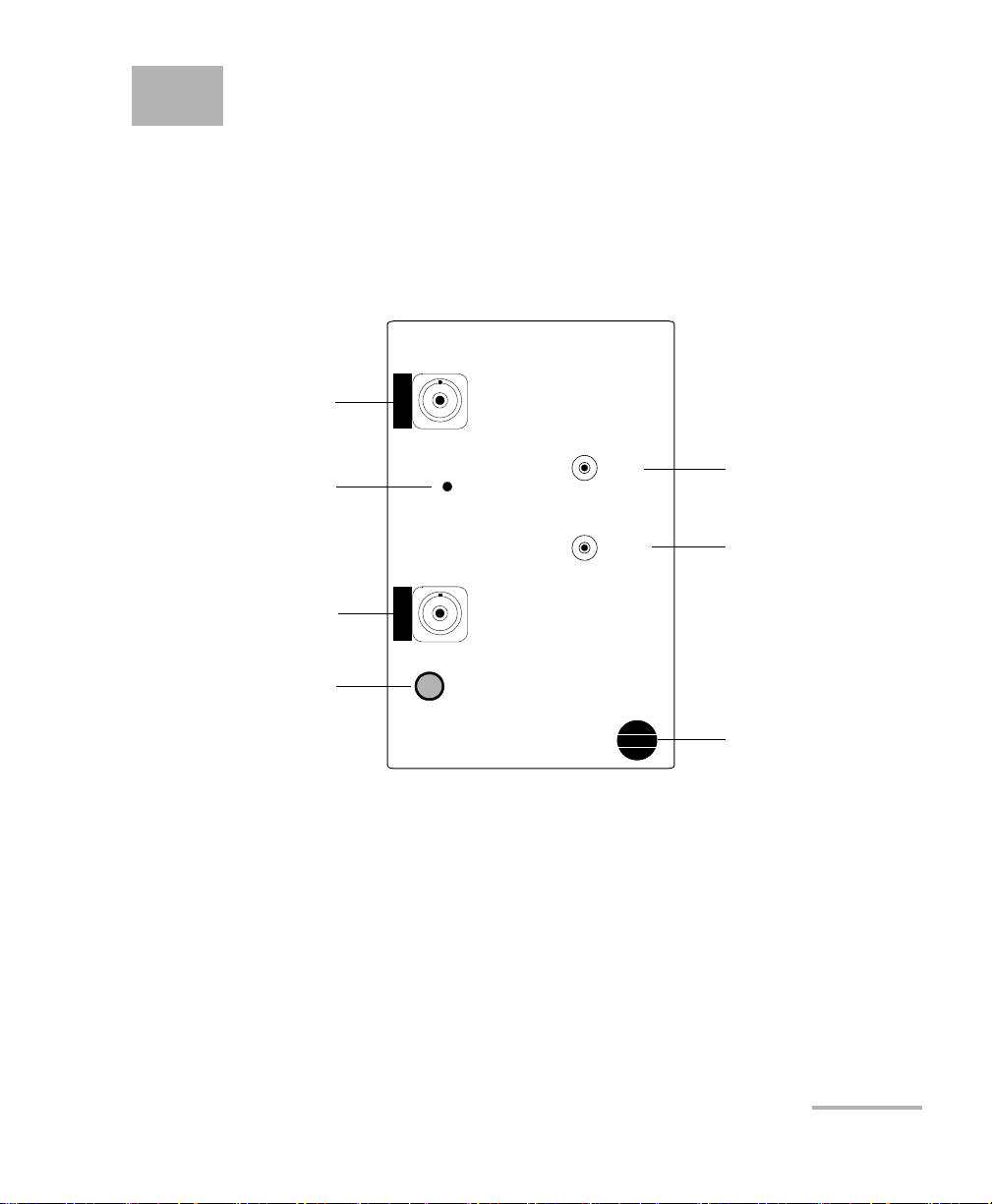
1 Introducing the IQS-2600B
IQS-2600B
ACTIVE
OUTPUT
MONITOR
OUTPUT
TRIG IN
TRIG OUT
Tunable Laser Source
Trigger In connector
Trigger Out connector
Retaining screw knob
Output connector
Active LED
Monitor output connector
LED push button
Tunable Laser Source
General Information
The IQS-2600B Tunable Laser Source addresses the testing requirements
for dense WDM component testing in the C- and L-bands.
Tunable Laser Source 1
The source has a medium coherence length that avoids problems such as
connector-induced interference and it is relatively immune to vibration. Its
linewidth is made up of several longitudinal modes that are present
simultaneously, resulting in no mode-hop-related measurement problems.
It also features a high-accuracy encoder for consistency in your results.
Your module may also feature the possibility to enable or disable the
automatic level control (ALC).
Page 8

Introducing the IQS-2600B Tunable Laser Source
Typic a l Ap pl ic ation s
The IQS-2600B Tunable Laser Source supports local control (via the
IQS Manager software) and remote control (through GPIB, RS-232, or
Ethernet TCP/IP using SCPI commands or the provided LabVIEW drivers).
For more information, refer to the IQS platform user guide.
Typical Applications
You can use your Tunable Laser Source to perform several tasks, such as
the following:
characterizing filters, multiplexers, Bragg gratings, and other DWDM
components
checking wavelength-dependent gain, noise contribution and
saturation properties
determining the spectral sensitivity of receivers and detectors
performing high-loss tests on passive components
2 IQS-2600B
Page 9

Introducing the IQS-2600B Tunable Laser Source
IQS-2600CT Tunable Laser Source for IQS-12004B DWDM Passive Component Test System
IQS-2600CT Tunable Laser Source for
IQS-12004B DWDM Passive Component Test
System
EXFO has modified its IQS-2600B Tunable Laser Source in order to
integrate it into the IQS-12004B DWDM Passive Component Test System. To
optimize the performance of the IQS-12004B, the optical attenuator
ensuring a constant power output from the tunable laser source has been
removed.
You can easily identify the type of tunable laser source you have. The unit
designed for the IQS-12004B system will bear the mention 2600CT, while
the stand-alone unit will bear the mention 2600B.
Every customer purchasing the IQS-12004B DWDM Passive Component
Test System for applications covering both the C- and L-bands will receive
an IQS-2600CT model. Even though the tunable laser source has been
modified, it can still be used as a stand-alone instrument using an IQS-600
Integrated Qualification System. However, you will notice a warning
message when turning the instrument on.
This warning informs you that the power output is not monitored and
cannot be controlled internally. Also note that the power stability and
repeatability values presented in the IQS-2600B specification sheet do not
apply to the IQS-2600CT.
Any other functionality or specification, particularly those concerning the
accuracy of the instrument and wavelength stability, will not be affected by
this design change.
Tunable Laser Source 3
Page 10

Introducing the IQS-2600B Tunable Laser Source
Conventions
Conventions
Before using the product described in this manual, you should understand
the following conventions:
WARNING
Indicates a potentially hazardous situation which, if not avoided,
could result in death or serious injury. Do not proceed unless you
understand and meet the required conditions.
CAUTION
Indicates a potentially hazardous situation which, if not avoided,
may result in minor or moderate injury. Do not proceed unless you
understand and meet the required conditions.
CAUTION
Indicates a potentially hazardous situation which, if not avoided,
may result in component damage. Do not proceed unless you
understand and meet the required conditions.
IMPORTANT
Refers to information about this product you should not overlook.
4 IQS-2600B
Page 11

2 Safety Information
While handling optical fibers, laser radiation may be encountered at
source output ports and fiber ends. Avoid long-term exposure to laser
radiation.
WARNING
Do not install or terminate fibers while a light source is active.
Never look directly into a live fiber and ensure that your eyes are
protected at all times.
WARNING
Use of controls, adjustments and procedures for operation and
maintenance other than those specified herein may result in
hazardous radiation exposure or impair the protection provided by
this unit.
Your instrument is a Class 1M laser product in compliance with standards
IEC 60825-1 and 21 CFR 1040.10. Invisible laser radiation may be
encountered at the output port.
The product is safe under reasonably foreseeable conditions of operation
but it may be hazardous if you use optics within a diverging or collimated
beam. Do not view directly with optical instruments.
Tunable Laser Source 5
Page 12

Page 13
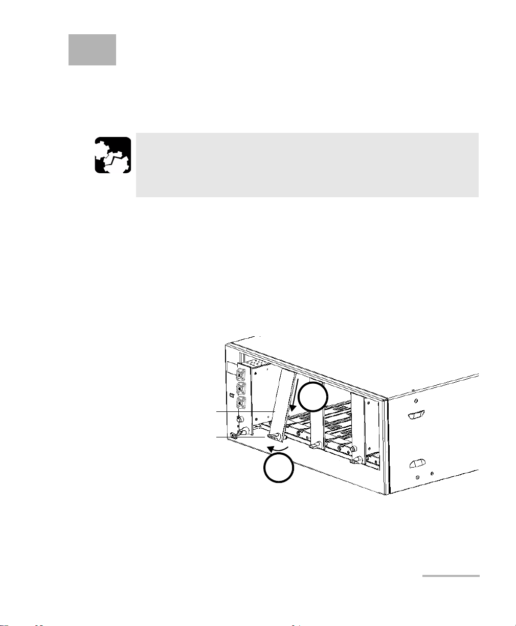
3 Getting Started with Your
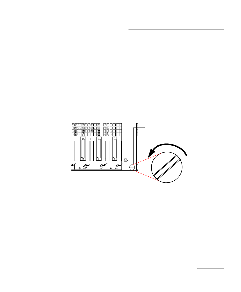
Retaining screw
knob
Protective cover
2b
2a
Tunable Laser Source
Inserting and Removing Test Modules
CAUTION
Never insert or remove a module while the controller unit and its
expansion units are turned on. This will result in immediate and
irreparable damage to both the module and unit.
To insert a module into the controller or expansion unit:
1. Exit IQS Manager and turn off all your units.
2. Remove the protective cover from the desired unused module slot.
2a. Pull the retaining screw knob firmly towards you and release the
bottom of the cover.
2b. Gently pull the top of the protective cover downwards, to remove
it from the unit grooves.
3. Position the module so that its front panel is facing you and the top and
bottom protruding edges are to your right.
Tunable Laser Source 7
Page 14
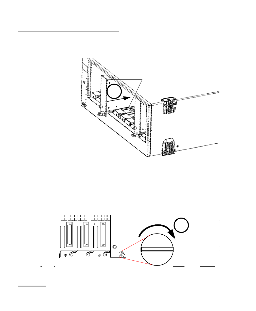
Getting Started with Your Tunable Laser Source
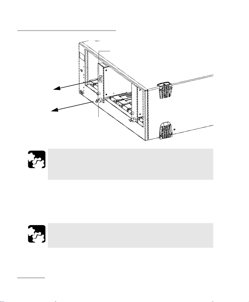
Retaining screw
Retaining screw knob
Protruding edges
(right side of module)
5
6
Inserting and Removing Test Modules
4. Insert the protruding edges of the module into the grooves of the unit’s
module slot.
5. Push the module all the way to the back of the slot, until the retaining
screw makes contact with the unit casing.
6. While applying slight pressure to the module, turn the retaining screw
knob (located at the bottom of the panel) clockwise until the knob is
horizontal.
This will secure the module into its “seated” position.
8 IQS-2600B
Page 15
Getting Started with Your Tunable Laser Source
Retaining screw knob
Inserting and Removing Test Modules
The module is correctly inserted when its front panel is flush with the front
panel of the controller or expansion unit.
When you turn on the controller unit, the startup sequence will
automatically detect your module.
Note: You can insert IQ modules into your controller or expansion unit; the
IQS Manager software will recognize them. However, the IQS-2600B
locking mechanism (retaining screw) will not work for IQ modules.
To remove a module from your controller or expansion unit:
1. While pulling gently on the knob, turn it counterclockwise until it stops.
The module will slowly be released from the slot.
2. Place your fingers underneath the module or hold it by the retaining
screw knob (NOT by the connector) and pull it out.
Tunable Laser Source 9
Page 16
Getting Started with Your Tunable Laser Source
YES
NO
Retaining screw
knob
Connector
Inserting and Removing Test Modules
CAUTION
Pulling out a module by a connector could seriously damage both
the module and connector. Always pull out a module by the
retaining screw knob.
3. Cover empty slots with the supplied protective covers.
3a. Slide the top of the protective cover into the upper grooves of the
unit.
3b. Snap the cover into place by pushing the retaining screw knob.
CAUTION
Failure to reinstall protective covers over empty slots will result in
ventilation problems.
10 IQS-2600B
Page 17
Getting Started with Your Tunable Laser Source
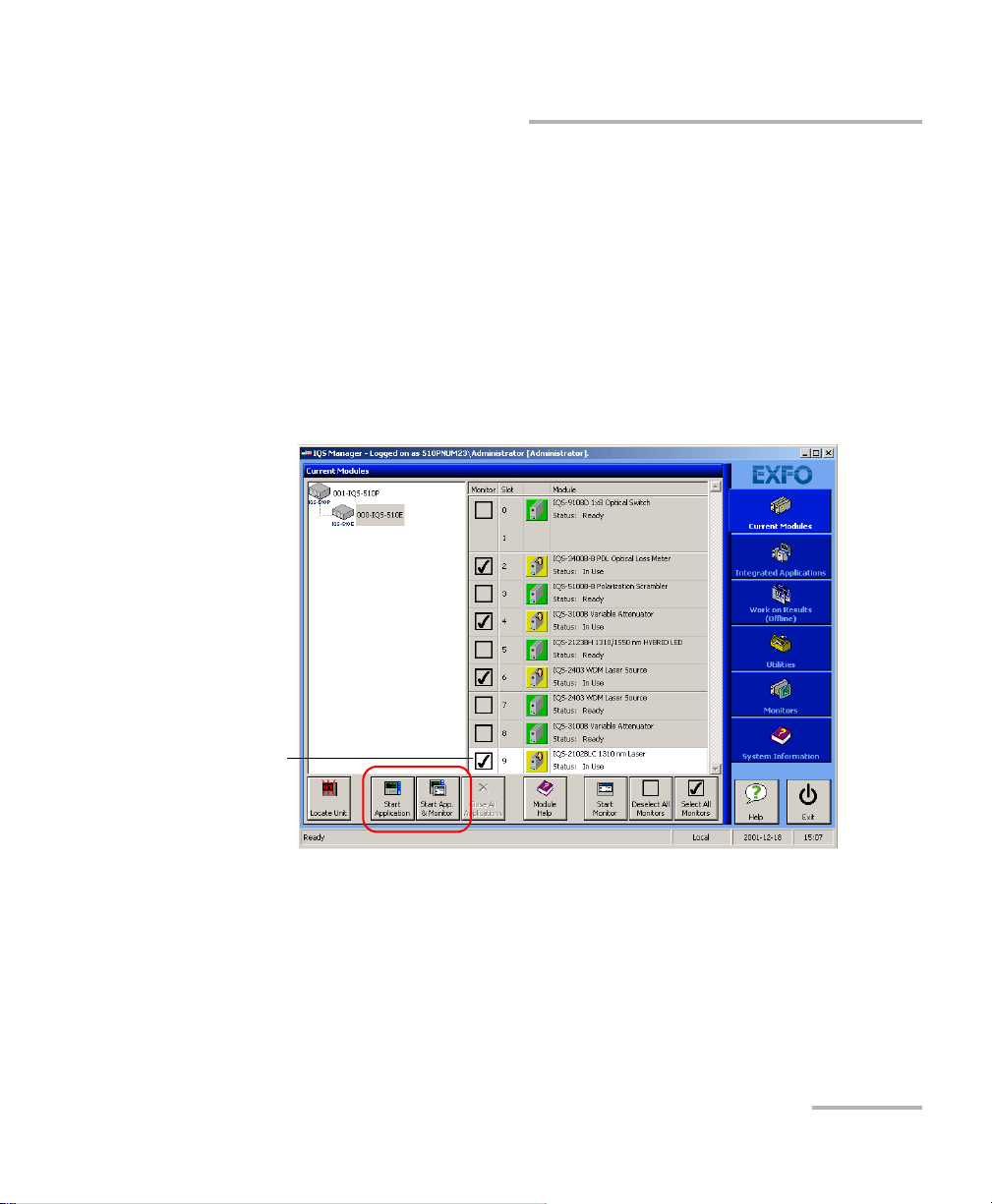
Highlighted module
(white background)
Starting the Tunable Laser Source Application
Starting the Tunable Laser Source Application
Your IQS-2600B Tunable Laser Source module can be configured and
controlled from its dedicated IQS Manager application.
Note: For details about IQS Manager, refer to the IQS platform user guide.
To start the application:
1. From the Current Modules function tab select the module to use.
It will turn white to indicate that it is highlighted.
2. Click Start Application.
OR
Press the green LED push button on the front of the corresponding
module.
You can also double-click its row.
Tunable Laser Source 11
Page 18
Getting Started with Your Tunable Laser Source
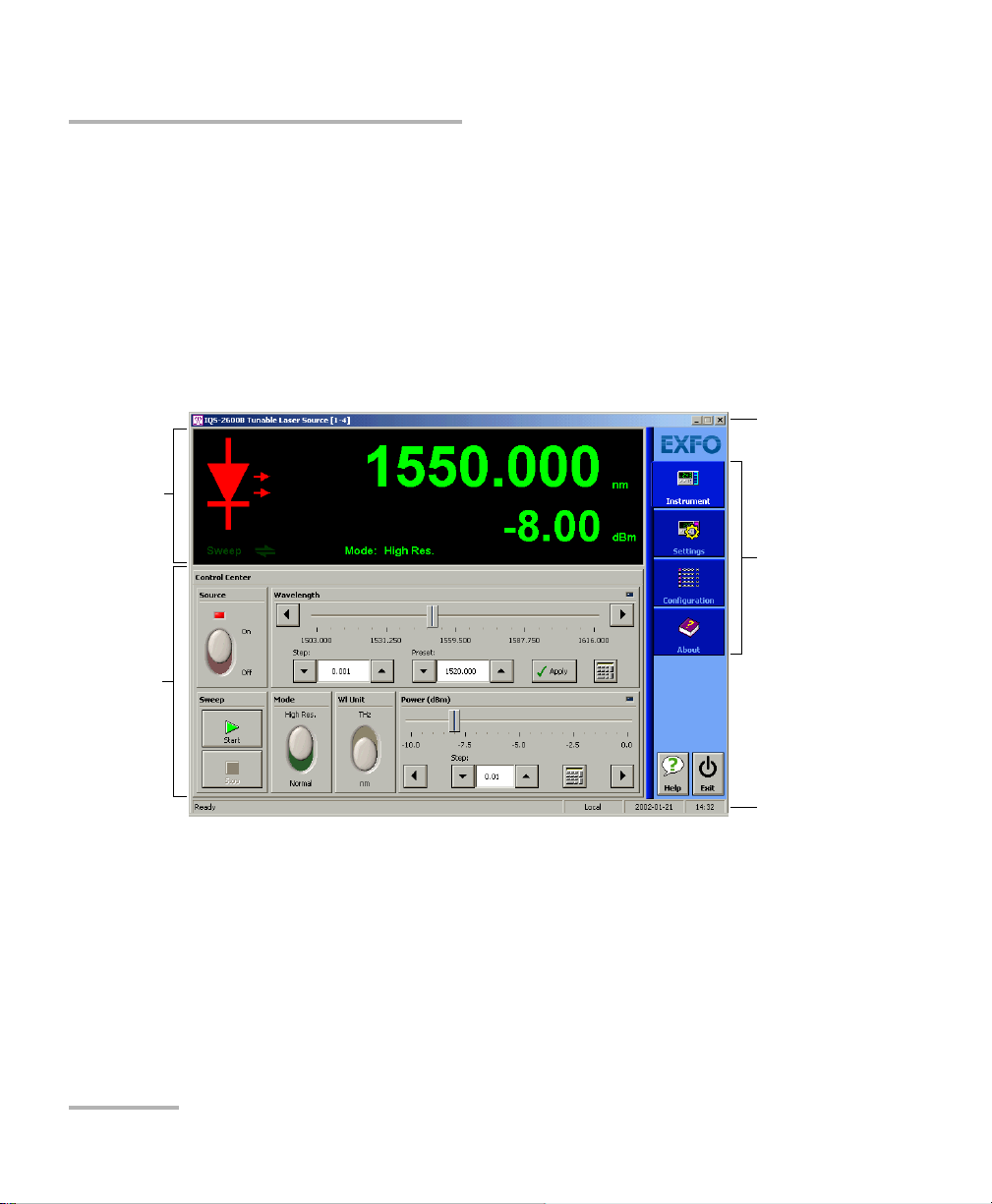
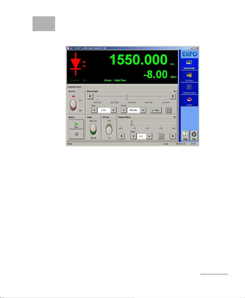
Data
display
Control
Center
Title bar
Function
tabs
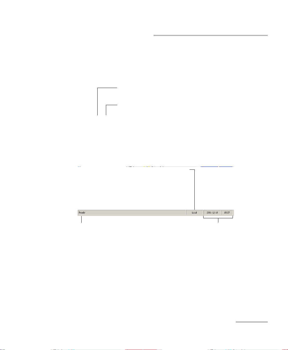
Status bar
Starting the Tunable Laser Source Application
Note: Pressing the LED push button will not activate or turn on the module.
Note: To start the corresponding monitor window at the same time, click Start
App. & Monitor. The window opens on the Monitors function tab.
The main window (shown below) contains all the commands required to
control the Tunable Laser Source:
?
12 IQS-2600B
Page 19
Getting Started with Your Tunable Laser Source
Slot number in which module is inserted
(0 identifies first slot)
Controller unit or expansion unit (1 to 999) housing
the module
[ 999 – 1 ]
Current date and timeModule/unit status
Local: Module controlled locally only.
Remote: Module controlled remotely, but
local commands can also be used.
Lockout: Module controlled remotely only.
Control mode
Starting the Tunable Laser Source Application
Title Bar
The title bar is located at the top of the main window. It displays the
module name and its position in the controller or expansion unit. The
module position is identified as follows:
Status Bar
The status bar, located at the bottom of the main window, identifies the
operational status of the IQS-2600B Tunable Laser Source.
For more information about automating or remotely controlling the
IQS-2600B Tunable Laser Source, refer to your platform user guide.
Tunable Laser Source 13
Page 20
Getting Started with Your Tunable Laser Source
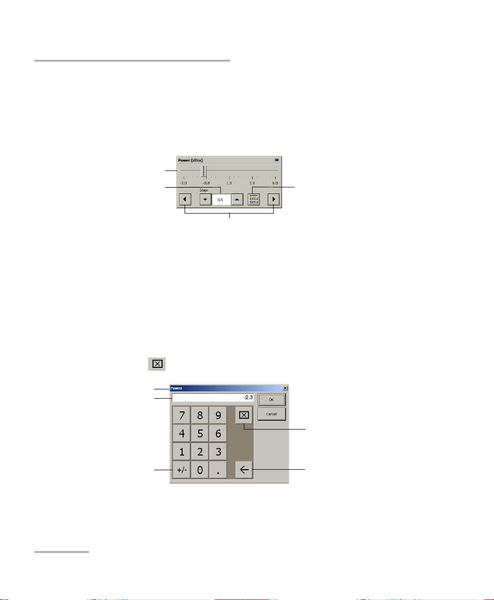
Numeric box
button
Fine-tuning
box
Slider
Navigation buttons
Parameter identification
Toggle button
Backspace button
(to correct a value)
Clear button
Entry display
Entering Values Using Sliders and Numeric Boxes
Entering Values Using Sliders and Numeric
Boxes
Many parameters in IQS Manager and module applications can be set
using the following tools.
Slider: Drag it to the desired value on the scale below.
Navigation buttons: Click either buttons to move the slider. The slider
moves by steps corresponding to the number in the fine-tuning box,
which you can change by using the up and down arrow buttons next to
the box. You cannot change the list of fine-tuning values from here.
Numeric box: Click it to display the on-screen numeric pad, which you
can use to enter a powe value.
To enter a value using the numeric box:
1. Use the button to clear the entry display.
14 IQS-2600B
2. Enter the value.
3. Click OK to confirm the value.
Page 21

Getting Started with Your Tunable Laser Source
Exiting the Application
Exiting the Application
Closing any application that is not currently being used helps freeing
system memory.
To close the application from the main window:
Click in the top right corner of the main window.
OR
Click the Exit button located at the bottom of the function bar.
To close all currently running applications:
From IQS Manager, click Close All Applications.
Tunable Laser Source 15
Page 22

Page 23
4 Setting Standard Parameters
The standard parameters are set through the Instrument function tab.
Tunable Laser Source 17
Page 24
Setting Standard Parameters
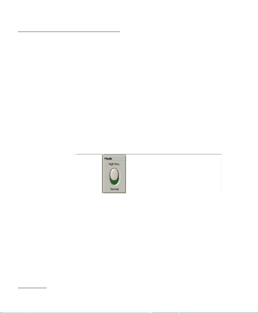
Switching between Normal and High-Resolution (HR) Modes
Switching between Normal and
High-Resolution (HR) Modes
You can use two different modes to select your values in your Instrument
function tab.
High-Resolution
Normal
In HR mode, the laser linewidth is reduced by a factor of 20 %. Typically, at
1550 nm, the Normal mode will produce a 1.6 GHz FWHM linewidth, while
the HR mode will produce a 1.4 GHz FWHM linewith. The tuning range
(or power at extreme wavelength) might be smaller in HR mode than in
Normal mode.
To select the operation mode:
Move the switch located in the Mode panel of the Instrument function tab.
.
18 IQS-2600B
Page 25
Setting Standard Parameters
Selecting the Display Unit
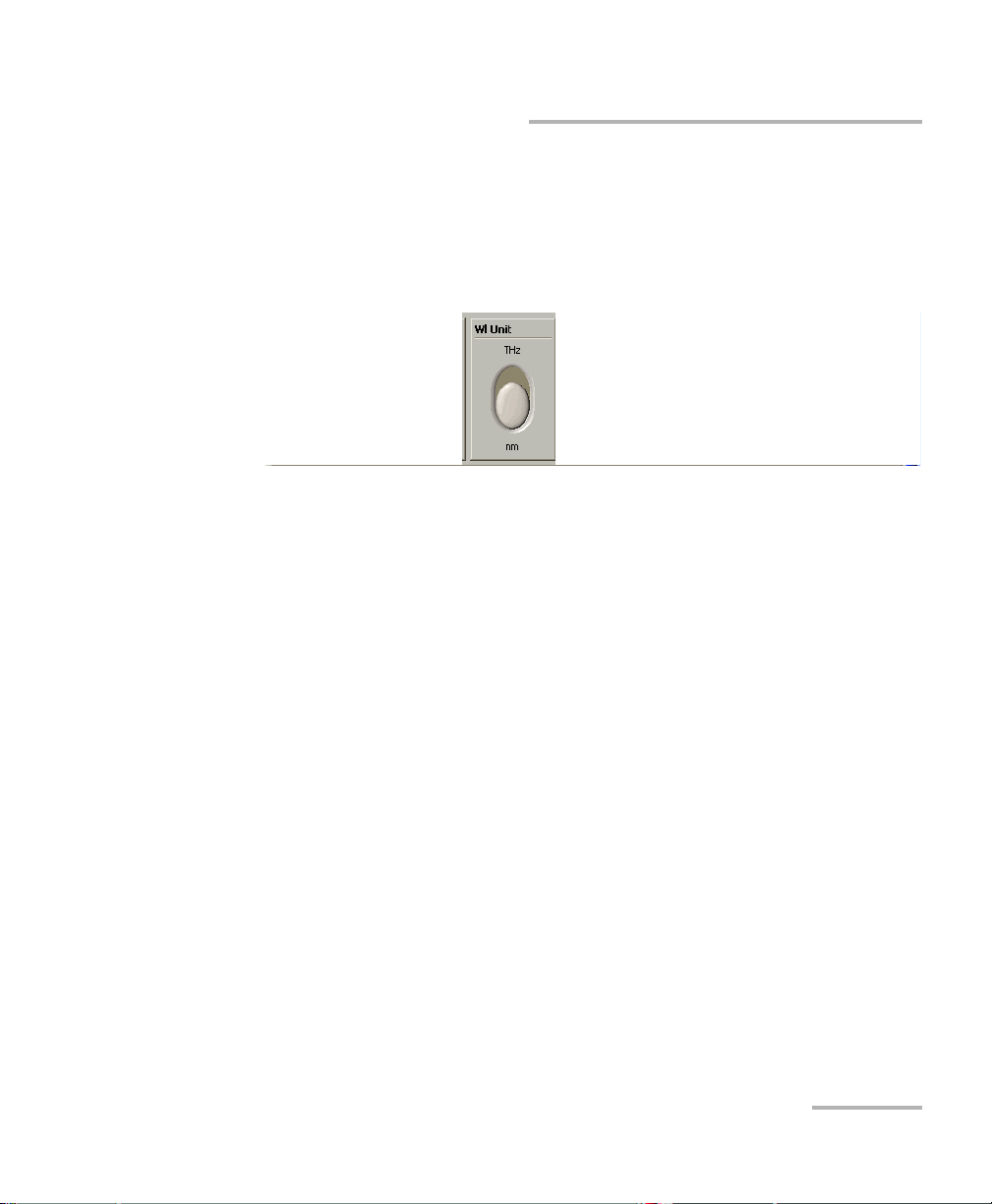
Selecting the Display Unit
It is possible to select the display unit with which you want to work.
To select the display units, use the switch located in the Wl. Unit panel of
the Instrument function tab.
.
The THz units are only supported in the main window. Settings in the
Settings function tab use nm as units.
Tunable Laser Source 19
Page 26
Setting Standard Parameters
Selecting a Wavelength
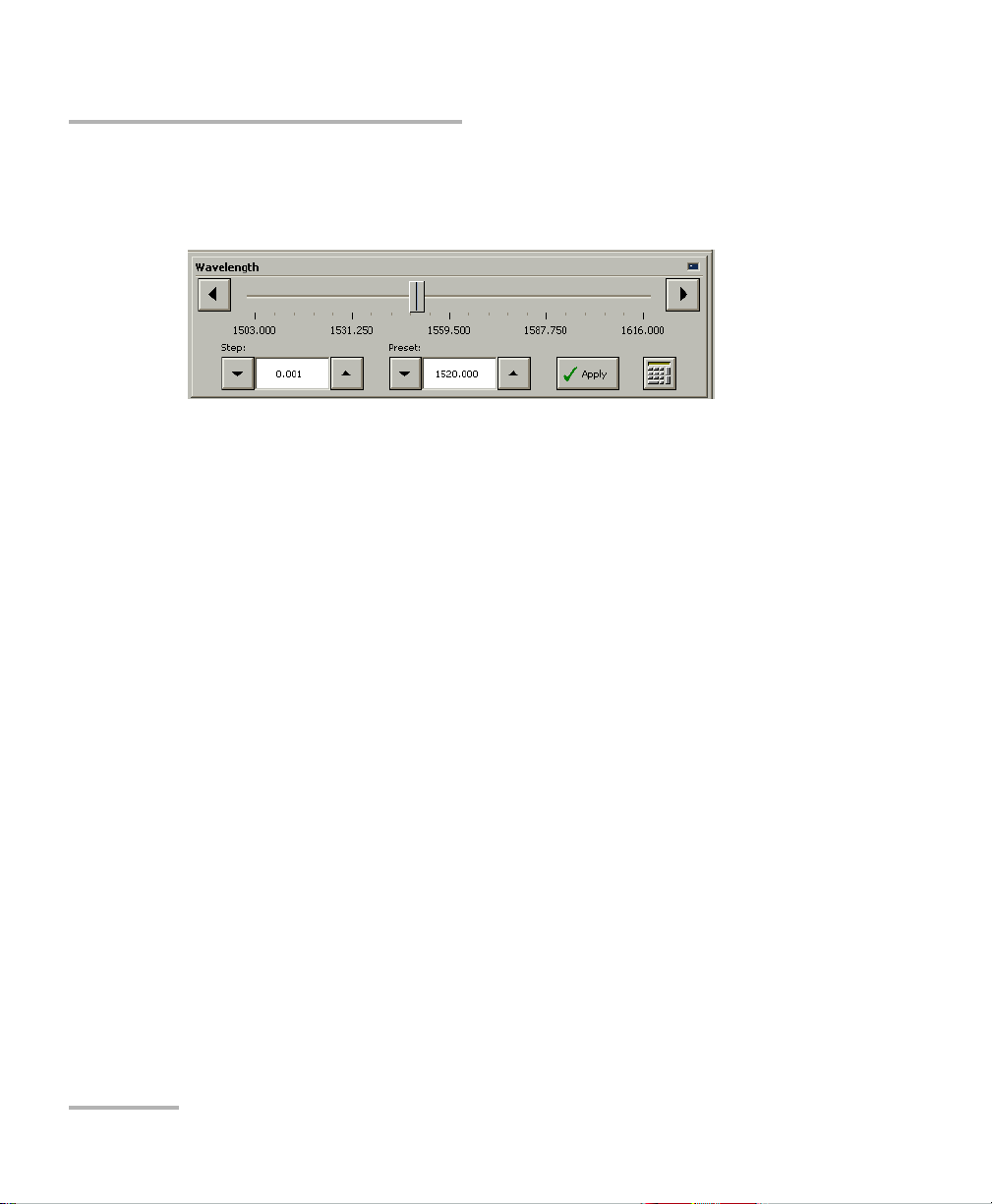
Selecting a Wavelength
There are several ways to select a wavelength for testing.
Whenever you use controls in the Wa velength panel, the LED on the upper
right-hand corner will light up to indicate which settings you are changing.
Entering a Wavelength Directly
Any desired wavelength within the operational limits of the source can be
entered directly by clicking on the numeric box button in the Wavelength
panel of the Instrument function tab.
If the set power cannot be maintained at the selected wavelength
(especially at extreme wavelengths), the displayed power value will flash,
a message appears in the status bar, and the power is no longer in constant
power mode. The output power stability and level will be the natural laser
emission.
To stop the power display from flashing and have the power regulation
work again, set the wavelength at an interval where the displayed power
can be reached, or decrease the power.
20 IQS-2600B
Page 27

Setting Standard Parameters
Selecting a Wavelength
Retrieving a Wavelength from a Stored List
To select a wavelength from the list of wavelengths already
saved in the internal memory:
1. In the Instrument function tab, use the arrow buttons next to the
Wavelength panel’s Preset list and select the wavelength you want.
2. Click Apply to use your new settings.
To add a wavelength to the list, see Adding Items to Lists on page 24.
Using a Step Value From a Stored List
To select a step from the list of existing step values:
In the Instrument function tab, use the arrow buttons next to the
Wavelength panel’s Step list to select the value you want.
Tunable Laser Source 21
Page 28
Setting Standard Parameters
Setting the Power
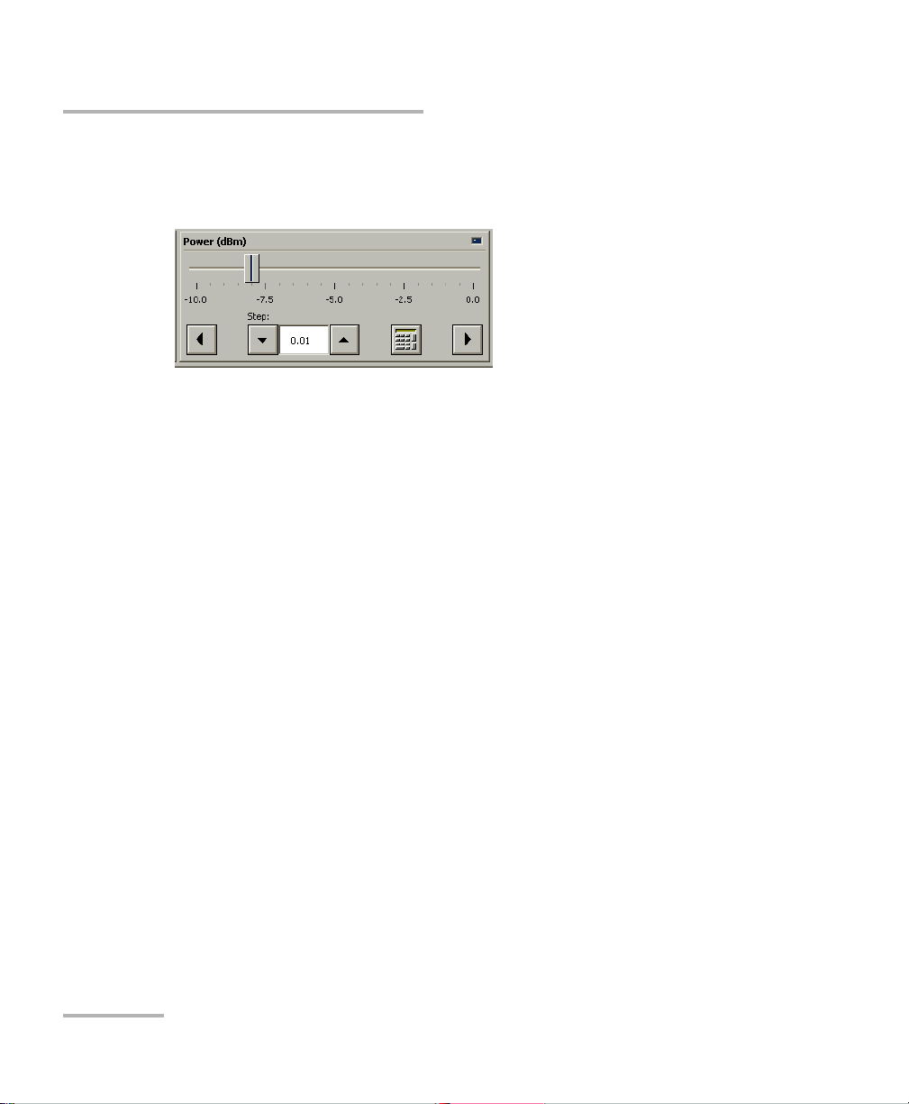
Setting the Power
There are several ways to select a power value for testing.
Whenever you use controls in the Power panel, the LED on the upper
right-hand corner will light up to indicate which settings you are changing.
Entering a Power Value Directly
Any desired power value within the operational limits of the source can be
entered directly by clicking on the numeric box button in the Power panel
of the Instrument function tab.
Your source can either be in Normal Power mode (where the ALC is
enabled), or in Max. Power mode (where the ALC is disabled).
To ch a nge t h e Automatic Level Control status, click the Max Power
button.
22 IQS-2600B
Page 29

Setting Standard Parameters
Setting the Power
Retrieving Power Step Value from a Stored List
To select a power step value from the list of existing values:
In the Instrument function tab, use the arrow buttons next to the Power
(dBm) panel’s Step list to select the value you want.
To add a wavelength to the list, see Adding Items to Lists on page 24.
Using the Slider
You can select a power value by using the slider in the Instrument function
tab.
For a more precise adjustment of your values, use the arrow buttons under
the slider.
Note: The power you select will affect the sweep range available. For example,
setting the power at 0 dBm will give you a range from 1515 nm to 1610 nm,
and setting the power at 10 dBm will give you a range of 1510 nm to
1612 nm. Please keep this in mind as you set the power for your sweep.
Tunable Laser Source 23
Page 30
Setting Standard Parameters
Adding Items to Lists
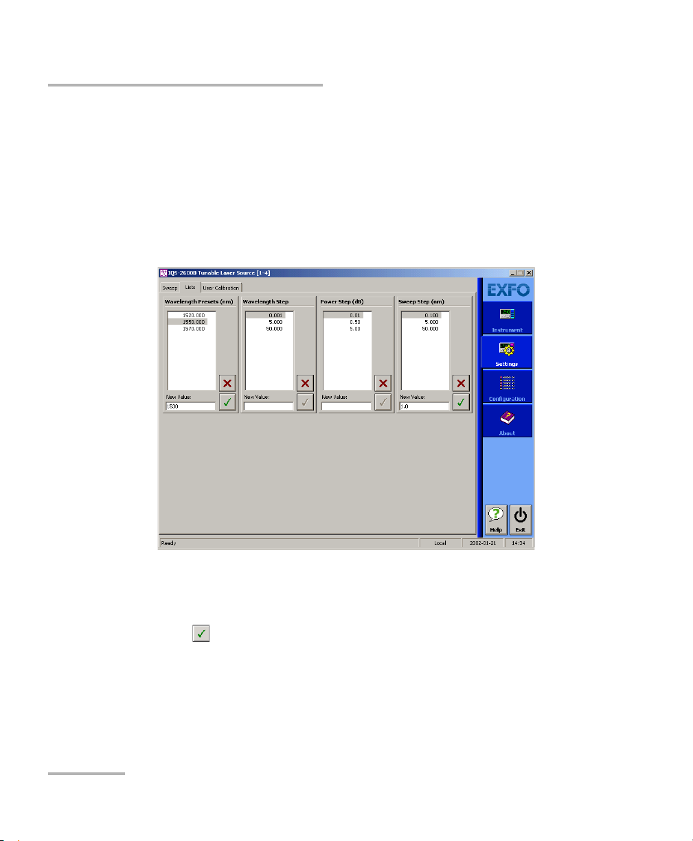
Adding Items to Lists
You can add items to the current Wavelength Presets, Wavelength Step,
Power Step and Sweep Step lists.
To add items:
1. Click the Settings function tab.
2. Select the Lists tab.
3. In the Wavelength Presets (nm), Wavelength Step, Power Step (dB)
or Sweep Step (nm) panels, depending on where you want to add a
value, type in the desired wavelength or step in the New Value box.
4. Click to add the value to the list.
5. Repeat steps 3 and 4 to add more values if needed.
24 IQS-2600B
Page 31

Setting Standard Parameters
Deleting Items from Lists
Deleting Items from Lists
You can delete items from the current Wavelength Presets, Wavelength
Step, Power Step and Sweep Step lists.
To d el e te it e ms :
1. Click the Settings function tab.
2. Select the Lists tab.
3. In the Wavelength Presets, Wavelength Step, Power Step or Sweep
Step panels, select the value to delete.
4. Click to delete it.
Tunable Laser Source 25
Page 32
Setting Standard Parameters
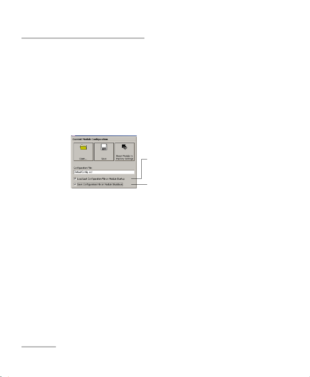
To save parameters being used
just before shutting down,
overwriting the previous file.
To always use the last saved
parameters when starting.
Saving and Recalling Configurations
Saving and Recalling Configurations
Once you have set the IQS-2600B Tunable Laser Source parameters, you
can save your custom configuration and recall it at any time. You can also
recall the factory-defined settings.
Saved configurations include all parameters set in the Control Center
(Instrument function tab) and in the Settings function tab (if present).
To save a configuration:
1. Select the Configuration function tab.
2. In the Current Module Configuration panel, enter the name you wish
to use for your configuration file.
It will be saved in
D:\IQS Manager\Configuration Files\(your_module)\.
3. Click Save.
26 IQS-2600B
Page 33

Setting Standard Parameters
Saving and Recalling Configurations
To recall a configuration:
1. Select the Configuration function tab.
2. Click Open.
3. Select the configuration file you wish to recall and confirm your action.
You are returned to the application and the new parameters are set.
To revert to factory settings:
1. Select the Configuration function tab.
2. Click the Reset Module to Factory Settings button.
IMPORTANT
Reverting to the factory settings will interrupt any module
operation in progress.
IMPORTANT
The operation may take a few seconds to complete.
Tunable Laser Source 27
Page 34

Page 35

5 Setting Sweep Parameters
Your Tunable Laser Source allows you to perform automatic wavelength
scans according to user-defined parameters. You can perform a
continuous sweep (the source will make one or several continuous
passes), or you can perform a step-by-step sweep (the signal wavelength
changes according to preset increments or steps).
Setting the Start and End Wavelengths
The wavelength scans and their lengths (or duration) depend on the start
and end wavelengths you set.
To set the wavelengths for your scans:
1. Click the Settings function tab.
2. Select the Sweep tab.
3. Enter the desired values in the appropriate boxes.
Note: The start and end wavelengths of the sweep can be set in ascending or
descending order, with a minimum value of 1.0 nm. The sweep will be
performed accordingly.
Tunable Laser Source 29
Page 36

Setting Sweep Parameters
Setting a Delay for the Sweep
Setting a Delay for the Sweep
A delay at the beginning of a sweep can allow you to coordinate more than
one unit.
To set the delay:
1. Select the Settings function tab.
2. In the Sweep tab, enter the desired time in the Delay box in 99:59:59
format.
If you set the delay to 00:00:00, the sweep will begin immediately upon
clicking Start in the Instrument function tab.
Selecting the Sweep Mode
You can select the sweep mode you want to perform in the Settings
function tab. The source will use either the Continuous or Stepped mode.
Using the Continuous Mode
To select the Continuous sweep mode, click the appropriate button in the
Sweep tab of the Settings function tab.
You can now select the speed for the sweep by entering a value in the box
(minimum of 10 nm/s and maximum of 50 nm/s).
Note: You cannot edit the duration of the scan. It will be automatically calculated
according to the speed and wavelength range.
30 IQS-2600B
Page 37

Setting Sweep Parameters
Selecting the Sweep Mode
Using the Stepped Mode
To select the Stepped sweep mode, click the appropriate button in the
Sweep tab of the Settings function tab.
To add or delete steps from the lists, see Adding Items to Lists on page 24
and Deleting Items from Lists on page 25.
You can also set the Pause length between the steps by entering the
desired value.
Tunable Laser Source 31
Page 38
Setting Sweep Parameters
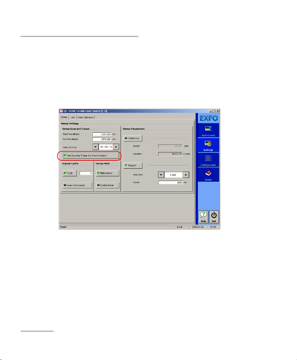
Selecting the Incoming Trigger Option
Selecting the Incoming Trigger Option
The incoming trigger option allows you to synchronize your sweeps with
signals from other units.
You can switch the incoming trigger option on or off by clicking Use
Incoming Trigger for Synchronization in the Sweep tab of the Settings
function tab.
For more information about the trigger option on your Tunable Laser
Source, see Trigger Option Theor y on page 129.
32 IQS-2600B
Page 39

Setting Sweep Parameters
Setting the Cycle Options
Setting the Cycle Options
The cycle options allow you to specify settings in both continuous and
stepped sweep modes.
You can set a specific number of cycles for the sweep to perform.
To set the number of cycles:
1. Click the Cycle button.
2. Enter the desired number of cycles in the box next to the button
(maximum 99).
Note: If you want the sweep to loop continuously, select the Loop Continuously
button instead.
Tunable Laser Source 33
Page 40

Setting Sweep Parameters
Setting the Sweep Direction
Setting the Sweep Direction
The sweep can be either unidirectional, meaning that it will only go in one
direction, or bidirectional, sweeping back and forth.
To set the direction of the sweep:
Select the desired sweep direction by selecting the appropriate button in
the Sweep tab of the Settings function tab.
34 IQS-2600B
Page 41

6 Operating your Tunable Laser
Source
Cleaning and Connecting Optical Fibers
IMPORTANT
To ensure maximum power and to avoid erroneous readings:
Always inspect fiber ends and make sure that they are clean as
explained below before inserting them into the port. EXFO is
not responsible for damage or errors caused by bad fiber
cleaning or handling.
Ensure that your patchcord has appropriate connectors. Joining
mismatched connectors will damage the ferrules.
To connect the fiber-optic cable to the port:
1. Inspect the fiber using a fiber inspection microscope. If the fiber is
clean, proceed to connecting it to the port. If the fiber is dirty, clean it as
explained below.
2. Clean the fiber ends as follows:
2a. Gently wipe the fiber end with a lint-free swab dipped in isopropyl
alcohol.
2b. Use compressed air to dry completely.
2c. Visually inspect the fiber end to ensure its cleanliness.
Tunable Laser Source 35
Page 42

Operating your Tunable Laser Source
Cleaning and Connecting Optical Fibers
3. Carefully align the connector and port to prevent the fiber end from
touching the outside of the port or rubbing against other surfaces.
If your connector features a key, ensure that it is fully fitted into the
port’s corresponding notch.
4. Push the connector in so that the fiber-optic cable is firmly in place,
thus ensuring adequate contact.
If your connector features a screwsleeve, tighten the connector
enough to firmly maintain the fiber in place. Do not overtighten, as this
will damage the fiber and the port.
Note: If your fiber-optic cable is not properly aligned and/or connected, you will
notice heavy loss and reflection.
36 IQS-2600B
Page 43

Operating your Tunable Laser Source
Bare metal
(or blue border)
indicates UPC
option
Green border
indicates APC
option
2 3 4
Installing the EXFO Universal Interface (EUI)
Installing the EXFO Universal Interface (EUI)
The EUI fixed baseplate is available for connectors with angled (APC) or
non-angled (UPC) polishing. A green border around the baseplate
indicates that it is for APC-type connectors.
To install an EUI connector adapter onto the EUI baseplate:
1. Hold the EUI connector adapter so the dust cap opens downwards.
2. Close the dust cap in order to hold the connector adapter more firmly.
3. Insert the connector adapter into the baseplate.
4. While pushing firmly, turn the connector adapter clockwise on the
baseplate to lock it in place.
Tunable Laser Source 37
Page 44

Operating your Tunable Laser Source
Status
indicator
Activating/Deactivating Light Emission
Activating/Deactivating Light Emission
Before turning on the Tunable Laser Source, please read the Safety
Information on page 5.
To activate or deactivate light emission, use the Source On/Off switch in
the Instrument function tab.
When the source is active, the LED on the module front panel lights up and
the Status indicator blinks and then appears in red with two arrows
pointing to the right. Once the source is deactivated, the LED on the
module front panel will turn off, the Status indicator will blink, then appear
in dark red, and the arrows will disappear.
IMPORTANT
To obtain optimum stability, a laser source should be allowed to
warm up for 60 minutes.
38 IQS-2600B
Page 45

Operating your Tunable Laser Source
Starting a Sweep
Starting a Sweep
After setting your sweep parameters as explained in Setting Sweep
Parameters on page 29 and that your source is turned on, you are ready to
start your sweep.
To start the sweep, click the Start button in the Instrument function tab.
To stop the sweep before it is completed, click Stop.
Note: You can stop the sweep at any time. Turning the laser on or off will also
stop the sweep.
Tunable Laser Source 39
Page 46

Page 47

7 Monitoring Your Tunable
Laser Source
When using your IQS-2600B Tunable Laser Source module, either alone or
with other modules in a test setup, you can view module data and status
using its monitor window in IQS Manager.
Using Monitor Windows
Monitor windows display basic data about modules. A combination of
resizable windows allows you to create an integrated data display (refer to
the platform user guide).
From the monitor window, you can change module parameters either by:
opening the module application to access all the functions
OR
using the QuickTools utility, which provides frequently used functions
from the application.
Tunable Laser Source 41
Page 48

Monitoring Your Tunable Laser Source
Selected modules
(checked)
Using Monitor Windows
To select modules and display their monitor windows:
1. On the Current Modules function tab, select the controller or
expansion unit containing the modules you want to monitor.
2. In the Monitor column, select the box next to each module you want
to monitor.
If you want to monitor all the modules in the current unit, click Select
All Monitors. If you want to clear your choices, click Deselect All
Monitors.
3. Click Start Monitor to apply your selection.
IQS Manager will display the selected monitor windows on the
Monitors function tab.
Note: To star t th e highlighted module’s corresponding application at the same
42 IQS-2600B
time, click Start App. & Monitor. The application will appear in a different
window.
Page 49

Monitoring Your Tunable Laser Source
Close
monitor
window
Rearrange
monitors
in columns
Reposition
monitor windows
Close all
monitor windows
Using Monitor Windows
Tunable Laser Source 43
Page 50

Monitoring Your Tunable Laser Source
Using QuickTools
Using QuickTools
With QuickTools, you can fine-tune your module directly, while keeping an
eye on your entire test setup.
Note: You can only access QuickTools if the module’s monitor window is selected
from the Monitors function tab and is currently active.
To start QuickTools:
1. From the Monitors function tab, elect the monitor window of the
module you wish to control.
2. Using the arrow button in the upper left corner, select QuickTools.
The corresponding monitor window flashes when QuickTools is
activated.
Note: If you want to open the actual application for your module rather than
QuickTools, click Show Controller.
44 IQS-2600B
Page 51

Monitoring Your Tunable Laser Source
Using QuickTools
To c lo s e Q ui c kTo ol s :
Click the Close button located at the top of the window.
OR
Click outside the QuickTools window.
To close a monitor window:
Click the button on the upper left of the monitor window and select
Remove Monitor.
OR
Click the Close All button at the bottom of the window.
Tunable Laser Source 45
Page 52

Page 53

8 Maintenance
To help ensure long, trouble-free operation:
Always inspect fiber-optic connectors before using them and clean
them if necessary.
Keep the unit free of dust.
Clean the unit casing and front panel with a cloth slightly dampened
with water.
Store unit at room temperature in a clean and dry area. Keep the unit
out of direct sunlight.
Avoid high humidity or significant temperature fluctuations.
Avoid unnecessary shocks and vibrations.
If any liquids are spilled on or into the unit, turn off the power
immediately, disconnect from any external power source, remove the
batteries and let the unit dry completely.
Use of controls, adjustments, and procedures for operation and
maintenance other than those specified herein may result in
hazardous radiation exposure.
WARNING
Tunable Laser Source 47
Page 54

Maintenance
Cleaning Fixed Connectors
Cleaning Fixed Connectors
Regular cleaning of connectors will help maintain optimum performance.
Do not try to disassemble the unit. Doing so would break the connector.
To clean fixed connectors:
1. Fold a lint-free wiping cloth in four to form a square.
2. Moisten the center of the lint-free wiping cloth with only one drop of
isopropyl alcohol.
Alcohol may leave traces if used abundantly. Avoid contact between
the tip of the bottle and the wiping cloth, and do not use bottles
that distribute too much alcohol at a time.
3. Gently wipe the connector threads three times with the folded and
moistened section of the wiping cloth.
IMPORTANT
IMPORTANT
Isopropyl alcohol takes approximately ten seconds to evaporate.
Since isopropyl alcohol is not absolutely pure, evaporation will
leave microscopic residue. Make sure you dry the surfaces before
evaporation occurs.
4. With a dry lint-free wiping cloth, gently wipe the same surfaces three
times with a rotating movement.
5. Throw out the wiping cloths after one use.
6. Moisten a cleaning tip (2.5 mm tip) with only one drop of isopropyl
alcohol.
48 IQS-2600B
Page 55

Maintenance
7
8
9
Cleaning Fixed Connectors
IMPORTANT
Alcohol may leave traces if used abundantly. Avoid contact between
the tip of the bottle and the cleaning tip, and do not use bottles
that distribute too much alcohol at a time.
7. Slowly insert the cleaning tip into the connector until it reaches the
ferrule inside (a slow clockwise rotating movement may help).
8. Gently turn the cleaning tip one full turn.
9. Continue to turn as you withdraw the cleaning tip.
10. Repeat steps 7 to 9, but this time with a dry cleaning tip (2.5 mm tip
provided by EXFO).
Note: Make sure you don’t touch the soft end of the cleaning tip and verify the
cleanliness of the cotton tip.
11. Throw out the cleaning tips after one use.
Tunable Laser Source 49
Page 56

Maintenance
Push
Tur n
Pull
3
4
5
Cleaning EUI Connectors
Cleaning EUI Connectors
Regular cleaning of EUI connectors will help maintain optimum
performance. There is no need to disassemble the unit.
If any damage occurs to internal connectors, the module casing will
have to be opened and a new calibration will be required.
To clean EUI connectors:
1. Remove the EUI from the instrument to expose the connector
baseplate and ferrule.
IMPORTANT
2. Moisten a 2.5 mm cleaning tip with one drop of isopropyl alcohol
(alcohol may leave traces if used abundantly).
3. Slowly insert the cleaning tip into the EUI adapter until it comes out on
the other side (a slow clockwise rotating movement may help).
4. Gently turn the cleaning tip one full turn, then continue to turn as you
withdraw it.
50 IQS-2600B
Page 57

Cleaning EUI Connectors
5. Repeat steps 3 to 4 with a dry cleaning tip.
Note: Make sure you don’t touch the soft end of the cleaning tip.
6. Clean the ferrule in the connector port as follows:
6a. Deposit one drop of isopropyl alcohol on a lint-free wiping cloth.
IMPORTANT
Isopropyl alcohol may leave residues if used abundantly or left to
evaporate (about 10 seconds).
Avoid contact between the tip of the bottle and the wiping cloth,
and dry the surface quickly.
6b. Gently wipe the connector and ferrule.
6c. With a dry lint-free wiping cloth, gently wipe the same surfaces to
ensure that the connector and ferrule are perfectly dry.
6d. Verify connector surface with a portable fiber-optic microscope
(for example, EXFO’s FOMS) or inspection probe (for
example, EXFO’s FIP).
Maintenance
WARNING
Verifying the surface of the connector WHILE THE UNIT IS ACTIVE
WILL result in permanent eye damage.
7. Put the EUI back onto the instrument (push and turn clockwise).
8. Throw out cleaning tips and wiping cloths after one use.
Tunable Laser Source 51
Page 58

Maintenance
Adjusting Your Unit According to Wavelength
Adjusting Your Unit According to Wavelength
It is possible to introduce an offset in your Tunable Laser Source to correct
a wavelength deviation as measured by a reference wavelength meter.
Note: A calibrated wavelength meter is required to perform a user calibration on
your unit.
To adjust your module at a certain wavelength:
1. Turn your Tunable Laser Source on.
2. Set your Tunable Laser Source at the desired wavelength as explained
in Selecting a Wavelength on page 20.
3. Select the Settings function tab.
4. Click the User Calibration tab.
5. Connect your IQS-2600B to a calibrated wavelength meter and enter
the measured wavelength in the corresponding box.
6. Click Adjust. Your unit will verify if there is a difference between the
value you have entered and its current wavelength position. If there is a
difference, it will add an offset to compensate.
This user-performed calibration feature can help you achieve better
absolute wavelength accuracy if, for example, you feel that conditions
outside the unit may have affected the calibration.
52 IQS-2600B
Page 59

Maintenance
Adjusting Your Unit According to Wavelength
The difference between the pre-selected wavelength and the measured
wavelength cannot be greater than ± 0.200 nm. If the difference between
the measured and preselected wavelengths is greater than ± 0.200 nm
(for example, if you have entered the wrong value), an error message will
be generated.
IMPORTANT
Note that the offset introduced into the Tunable Laser Source with
this software feature cannot be disabled. To correct for a handling
error during the procedure, you must repeat the steps described
above with a calibrated wavelength meter.
Tunable Laser Source 53
Page 60

Maintenance
Recalibrating the Unit
Recalibrating the Unit
Manufacturing and service center calibrations are based on the
ISO/IEC 17025 Standard, which states that calibration documents must not
contain a recommended calibration interval, unless this has been
previously agreed upon with the customer.
Validity of specifications depends on operating conditions. For example,
the calibration validity period can be longer or shorter depending on the
intensity of use, environmental conditions and unit maintenance. You
should determine the adequate calibration interval for your unit according
to your accuracy requirements.
Under normal use, EXFO recommends calibrating your unit every year.
Recycling and Disposal (Applies to European Union Only)
For complete recycling/disposal information as per European Directive
WEEE 2002/96/EC, visit the EXFO Web site at www.exfo.com/recycle.
54 IQS-2600B
Page 61

9 Troubleshooting
Solving Common Problems
If you encounter one of the problems listed below, try to solve it first with
the given information. In all cases, if the problem persists after performing
a recommended action, contact EXFO immediately.
Problem Probable Cause Recommended Action
Source appears unstable. Stabilization time
was insufficient.
Reflection is
destabilizing the
source.
There was an
ambient
temperature
variation.
Wait at least 60 minutes for
optimum stabilization.
Use an optical isolator with
your source.
Control ambient
temperature.
Tunable Laser Source 55
Page 62

Troubleshooting
Viewing Online Documentation
Viewing Online Documentation
An online version of the IQS-2600B Tunable Laser Source user guide is
available at all times from the application.
To access the online user guide:
Click Help in the function bar.
56 IQS-2600B
Page 63

Troubleshooting
Ver.
Mfg.
date
P/N
S/N
Made in Canada QST442B
465 Godin Avenue
Vanier (Quebec) G1M 3G7 CANADA
**************** A
January 2020
542392-3D
IQS-2600B-XX-XX
Connector code
Fiber type
Contacting the Technical Support Group
Contacting the Technical Support Group
To obtain after-sales service or technical support for this product, contact
EXFO at one of the following numbers. The Technical Support Group is
available to take your calls from Monday to Friday, 8:00 a.m. to 7:00 p.m.
(Eastern Time in North America).
For detailed information about technical support, visit the EXFO Web site at
www.exfo.com.
Technical Support Group
400 Godin Avenue
Quebec (Quebec) G1M 2K2
CANADA
To accelerate the process, please have information such as the name and
the serial number (see the product identification label—an example is
shown below), as well as a description of your problem, close at hand.
1 866 683-0155 (USA and Canada)
Tel.: 1 418 683-5498
Fax: 1 418 683-9224
support@exfo.com
Tunable Laser Source 57
Page 64

Troubleshooting
Contacting the Technical Support Group
You may also be requested to provide software and module version
numbers.This information, as well as technical support contact
information, can be found in the About function tab.
Select the Technical Support tab to view phone numbers and active
Internet links to EXFO’s Technical Support Group. Use these links to
send an information request by e-mail or to access EXFO’s web site.
Select the Module Information tab to view the module identification,
serial number and firmware version.
58 IQS-2600B
Page 65

Troubleshooting
Transportation
Transportation
Maintain a temperature range within specifications when transporting the
unit. Transportation damage can occur from improper handling. The
following steps are recommended to minimize the possibility of damage:
Pack the unit in its original packing material when shipping.
Avoid high humidity or large temperature fluctuations.
Keep the unit out of direct sunlight.
Avoid unnecessary shocks and vibrations.
Tunable Laser Source 59
Page 66

Page 67

10 Warranty
General Information
EXFO Inc. (EXFO) warrants this equipment against defects in material and
workmanship for a period of two years from the date of original shipment.
EXFO also warrants that this equipment will meet applicable specifications
under normal use.
During the warranty period, EXFO will, at its discretion, repair, replace,
or issue credit for any defective product, as well as verify and adjust the
product free of charge should the equipment need to be repaired or if the
original calibration is erroneous. If the equipment is sent back for
verification of calibration during the warranty period and found to meet all
published specifications, EXFO will charge standard calibration fees.
THIS WARRANTY IS IN LIEU OF ALL OTHER WARRANTIES EXPRESSED,
IMPLIED, OR STATUTORY, INCLUDING, BUT NOT LIMITED TO, THE
IMPLIED WARRANTIES OF MERCHANTABILITY AND FITNESS FOR A
PARTICULAR PURPOSE. IN NO EVENT SHALL EXFO BE LIABLE FOR
SPECIAL, INCIDENTAL, OR CONSEQUENTIAL DAMAGES.
Liability
EXFO shall not be liable for damages resulting from the use of the product,
nor shall be responsible for any failure in the performance of other items to
which the product is connected or the operation of any system of which
the product may be a part.
EXFO shall not be liable for damages resulting from improper usage or
unauthorized modification of the product, its accompanying accessories
and software.
Tunable Laser Source 61
Page 68

Warranty
Exclusions
Exclusions
EXFO reserves the right to make changes in the design or construction of
any of its products at any time without incurring obligation to make any
changes whatsoever on units purchased. Accessories, including but not
limited to fuses, pilot lamps, batteries and universal interfaces (EUI) used
with EXFO products are not covered by this warranty.
This warranty excludes failure resulting from: improper use or installation,
normal wear and tear, accident, abuse, neglect, fire, water, lightning or
other acts of nature, causes external to the product or other factors beyond
the control of EXFO.
Certification
EXFO certifies that this equipment met its published specifications at the
time of shipment from the factory.
62 IQS-2600B
Page 69

Warranty
Service and Repairs
Service and Repairs
EXFO commits to providing product service and repair for five years
following the date of purchase.
To send any equipment for service or repair:
1. Call one of EXFO’s authorized service centers (see EXFO Service
Centers Worldwide on page 64). Support personnel will determine if
the equipment requires service, repair, or calibration.
2. If equipment must be returned to EXFO or an authorized service
center, support personnel will issue a Return Merchandise
Authorization (RMA) number and provide an address for return.
3. If possible, back up your data before sending the unit for repair.
4. Pack the equipment in its original shipping material. Be sure to include
a statement or report fully detailing the defect and the conditions under
which it was observed.
5. Return the equipment, prepaid, to the address given to you by support
personnel. Be sure to write the RMA number on the shipping slip. EXFO
will refuse and return any package that does not bear an RMA number.
Note: A test setup fee will apply to any returned unit that, after test, is found to
meet the applicable specifications.
After repair, the equipment will be returned with a repair report. If the
equipment is not under warranty, you will be invoiced for the cost
appearing on this report. EXFO will pay return-to-customer shipping costs
for equipment under warranty. Shipping insurance is at your expense.
Routine recalibration is not included in any of the warranty plans. Since
calibrations/verifications are not covered by the basic or extended
warranties, you may elect to purchase FlexCare Calibration/Verification
Packages for a definite period of time. Contact an authorized service center
(see EXFO Service Centers Worldwide on page 64).
Tunable Laser Source 63
Page 70

Warranty
EXFO Service Centers Worldwide
EXFO Service Centers Worldwide
If your product requires servicing, contact your nearest authorized service
center.
EXFO Headquarters Service Center
400 Godin Avenue
Quebec (Quebec) G1M 2K2
CANADA
EXFO Europe Service Center
Omega Enterprise Park, Electron Way
Chandlers Ford, Hampshire S053 4SE
ENGLAND
EXFO Telecom Equipment
(Shenzhen) Ltd.
3rd Floor, Building 10,
Yu Sheng Industrial Park (Gu Shu
Crossing), No. 467,
National Highway 107,
Xixiang, Bao An District,
Shenzhen, China, 518126
1 866 683-0155 (USA and Canada)
Tel.: 1 418 683-5498
Fax: 1 418 683-9224
support@exfo.com
Tel.: +44 2380 246810
Fax: +44 2380 246801
support.europe@exfo.com
Tel: +86 (755) 2955 3100
Fax: +86 (755) 2955 3101
support.asia@exfo.com
64 IQS-2600B
Page 71

A Technical Specifications
WAVELENGTH
Range (nm) 1510 to 1612
Display resolution (pm) 1
Effective spectral linewidth FWHM
b
(GHz) 1.3 (typical)
Repeatability
c
(pm) 10 measurements ±2.5 (6 = 5)
Stability
c
(pm) 1 hour ±6 (6 = 12)
Uncertainty
d
(pm) ±15
Sweep rate
e
(nm/s) Maximum 50
Minimum 2
Tuning time
f
(ms) 75 (typical)
Notes
a. Specifications are valid at 23 °C ± 1 °C after one-hour warmup time.
b. FWHM: full width at half maximum. The specification is valid at 1580 nm, where
it corresponds to 12 pm.
Given in HR mode.
Typical 700 MHz at 1610 nm and 2 GHz at 1520 nm.
Linewidth is Gaussian-like and produces a coherence length of about 15 cm
when propagating into SMF-28 fiber type.
c. Expressed as ± half the difference between the maximum and
minimum values measured.
d. User calibration may be required.
e. Operating in continuous sweep.
f. 1 nm step, one complete step through GPIB in manual mode with FLS-2600B.
g. In normal mode. Operating in high-resolution mode (HR) typically reduces power level
at extreme wavelengths, therefore shortening the tuning range by a few nanometers.
h. At connector output of the source.
i. In the 1515 nm to 1610 nm range.
SSE: source spontaneous emission
RBW: spectral resolution bandwidth
j. ALC: Automatic level (or power) control.
k. For 1 dB step 10 % to 90 % response time.
POWER
Output power
g, h
(dBm) From 1515 nm to 1610 nm * 0
From 1510 nm to 1612 nm * —10
Stability
c
(dB) 15 minutes ±0.005 (6 = 0.01)
1 hour ±0.01 (6 = 0.02)
Repeatability for a wavelength change
c
(dB) 10 measurements ±0.015 (6 = 0.03)
Signal to SSE
g, i
(dB) From 1515 nm to 1610 nm * 75 (typical)
±1 nm from peak with RBW 0.1 nm From 1550 nm to 1610 nm * 80 (typical)
Signal to total SSE (dB) * 45
50 (typical)
INTERNAL VARIABLE ATTENUATOR
Attenuation range (dB) 10
Linearity with attenuation (dB) ±0.3 (typical)
Repeatability for specific wavelength
c
(dB) ±0.005 (6 = 0.010) (typical)
Response time
k
(s) 0.5 (typical
)
IMPORTANT
The following technical specifications can change without notice.
The information presented in this section is provided as a reference
only. To obtain this product’s most recent technical specifications,
visit the EXFO Web site at www.exfo.com.
Tunable Laser Source 65
Page 72

Technical Specifications
GENERAL SPECIFICATIONS
Output fiber type SMF-28
Operating temperature 10 °C to 40 °C (50 °F to 104 °F)
Storage temperature —10 °C to 50 °C (14 °F to 122 °F)
Dimensions (H x W x D)
IQS 125 mm x 74 mm x 282 mm (4
15
/16 in x 2 15/16 in x 11 1/8 in)
FLS 117 mm x 222 mm x 333 mm (4
5
/8 in x 8 3/4 in x 13 3/8 in)
Weight 1.4 kg (3.1 lb) 3.4 kg (7.4 lb)
Instruments Drivers
LabVIEW™ drivers and SCPI commands
Remote Control
With FLS-2600B: GPIB (IEEE-488.1, IEEE-488.2) and RS-232.
With IQS-500 or IQS-600: GPIB (IEEE-488.1, IEEE-488.2), Ethernet and RS-232.
Standard Accessories
User Guide, Certificate of Compliance and AC power cord
66 IQS-2600B
Page 73

WAVELENGTH
Range (nm) 1510 to 1612
Display resolution (pm) 1
Effective spectral linewidth FWHM
b
(GHz) 1.3 (typical)
Repeatability
c
(pm) 10 measurements ±2.5 (6 = 5)
Stability
c
(pm) 1 hour ±6 (6 = 12)
Uncertainty
d
(pm) ±15
Sweep rate
e
(nm/s) Maximum 50
Minimum 2
Tuning time
f
(ms) 75 (typical)
Notes
a. Specifications are valid at 23 °C ± 1 °C after one-hour warmup time.
b. FWHM: full width at half maximum. The specification is valid at 1580 nm, where
it corresponds to 12 pm.
Given in HR mode.
Typical 700 MHz at 1610 nm and 2 GHz at 1520 nm.
Linewidth is Gaussian-like and produces a coherence length of about 15 cm
when propagating into SMF-28 fiber type.
c. Expressed as ± half the difference between the maximum and
minimum values measured.
d. User calibration may be required.
e. Operating in continuous sweep.
f. 1 nm step, one complete step through GPIB in manual mode with FLS-2600B.
g. In normal mode. Operating in high-resolution mode (HR) typically reduces power level
at extreme wavelengths, therefore shortening the tuning range by a few nanometers.
h. At connector output of the source.
i. In the 1515 nm to 1610 nm range.
SSE: source spontaneous emission
RBW: spectral resolution bandwidth
j. ALC: Automatic level (or power) control.
k. For 1 dB step 10 % to 90 % response time.
POWER
Output power
g, h
(dBm) From 1515 nm to 1610 nm * 0
From 1510 nm to 1612 nm * —10
Stability
c
(dB) 15 minutes ±0.005 (6 = 0.01)
1 hour ±0.01 (6 = 0.02)
Repeatability for a wavelength change
c
(dB) 10 measurements ±0.015 (6 = 0.03)
Signal to SSE
g, i
(dB) From 1515 nm to 1610 nm * 75 (typical)
±1 nm from peak with RBW 0.1 nm From 1550 nm to 1610 nm * 80 (typical)
Signal to total SSE (dB) * 45
50 (typical)
INTERNAL VARIABLE ATTENUATOR
Attenuation range (dB) 10
Linearity with attenuation (dB) ±0.3 (typical)
Repeatability for specific wavelength
c
(dB) ±0.005 (6 = 0.010) (typical)
Response time
k
(s) 0.5 (typical)
Technical Specifications
Tunable Laser Source 67
Page 74

Technical Specifications
GENERAL SPECIFICATIONS
Output fiber type SMF-28
Operating temperature 10 °C to 40 °C (50 °F to 104 °F)
Storage temperature —10 °C to 50 °C (14 °F to 122 °F)
Dimensions (H x W x D)
IQS 125 mm x 74 mm x 282 mm (4
15
/16 in x 2 15/16 in x 11 1/8 in)
FLS 117 mm x 222 mm x 333 mm (4
5
/8 in x 8 3/4 in x 13 3/8 in)
Weight 1.4 kg (3.1 lb) 3.4 kg (7.4 lb)
Instruments Drivers
LabVIEW™ drivers and SCPI commands
Remote Control
With FLS-2600B: GPIB (IEEE-488.1, IEEE-488.2) and RS-232.
With IQS-500 or IQS-600: GPIB (IEEE-488.1, IEEE-488.2), Ethernet and RS-232.
Standard Accessories
User Guide, Certificate of Compliance and AC power cord
68 IQS-2600B
Page 75

B SCPI Command Reference
IQS controller or expansion unit
identification number (for example, 001)
Instrument slot number (0 to 9)
XXXY
This appendix presents detailed information on the commands and
queries supplied with your IQS-2600B Tunable Laser Source.
IMPORTANT
Since the IQS controllers and expansion units can house many
instruments, you must explicitly specify which instrument you want
to remotely control.
You must add the following mnemonic at the beginning of any
command or query that you send to an instrument:
LINStrument<LogicalInstrumentPos>:
where <LogicalInstrumentPos> corresponds to the identification
number of the instrument.
For information on modifying unit identification, refer to your
platform user guide.
Tunable Laser Source 69
Page 76

SCPI Command Reference
Quick Reference Command Tree
Quick Reference Command Tree
Command Paramet er(s) P.
ABORt[1..n] 72
CALibration[1..n]WAVel engt h <ReadoutValue> 73
INITiate[1..n] [IMMediate] 75
SOURce[1..n] POWer ALC [STATe] <State> 76
[STATe]? 77
[LEVel] [IMMediate] [AMPLitude] <OutputPower[<wsp>DBM]>|MA
[AMPLitude]? [MAXimum|MINimum|DEFault] 80
STATe <PowerState> 82
STATe? 83
WAVelength [CW] <Wavelength[<wsp>M|HZ]>|MA
[CW]? [MAXimum|MINimum|DEFault] 86
MODE NORMal|HRESolution 88
MODE? 89
SWEep MODE CONTinuous|STEPped 90
MODE? 91
CYCLe <Cycle>|MAXimum|MINimum|DE
CYCLe? [MAXimum|MINimum|DEFault] 94
DIRection ONEWay|TWOWay 96
DIRection? 97
Ximum|MINimum|DEFault
Ximum|MINimum|DEFault
Fau l t
78
84
92
70 IQS-2600B
Page 77

SCPI Command Reference
Quick Reference Command Tree
Command Paramet er(s) P.
REPeat CONTinuous|NCONtinuous 99
REPeat? 100
STARt <StartWavelength[<wsp>M|HZ]>|
STARt? [MAXimum|MINimum|DEFault] 103
STOP <StopWavelength[<wsp>M|HZ]>|
STOP? [MAXimum|MINimum|DEFault] 107
SPEed <Speed>|MAXimum|MINimum|D
SPEed? [MAXimum|MINimum|DEFault] 110
STATe <State> 112
STATe? 114
TIME? 115
STEP [WIDTh] <StepWidth[<wsp>M|HZ]>|MAXi
[WIDTh]? [MAXimum|MINimum|DEFault] 118
DWELl <DwellTime[<wsp>S]>|MAXimu
DWELl? [MAXimum|MINimum|DEFault] 122
MAXimum|MINimum|DEFault
MAXimum|MINimum|DEFault
EFault
mum|MINimum|DEFault
m|MINimum|DEFault
101
105
109
116
120
TRIGger[1..n] [SEQuence] INPut DISabled|SSWeep 124
INPut? 125
UNIT[1..n] SPECtrum M|HZ 126
SPECtrum? 127
Tunable Laser Source 71
Page 78

SCPI Command Reference
Product-Specific Commands—Description
Product-Specific Commands—Description
Description This command is used to stop running scan.
Syntax :ABORt[1..n]
Parameter(s) None
Example(s) SOUR:WAV:SWE:REP NCON
:ABORt[1..n]
ABORt is an event and cannot be queried as
there is no state associated with it.
SOUR:WAV:SWE:DIR BOTH
SOUR:WAV:SWE:CYCL 12
SOUR:WAV:SWE:STAR 1523.45NM
SOUR:WAV:SWE:STOP 1600.45NM
SOUR:WAV:SWE:SPE 25.56NM
SOUR:WAV:SWE:MODE CONT
TRIG SEQ:INP DISABLED
INIT:IMM
ABORT (abort sweep)
See Also INITiate[1..n][:IMMediate]
SOURce[1..n]:WAVelength:SWEep:STATe?
SOURce[1..n]:WAVelength:SWEep:STATe
72 IQS-2600B
Page 79

SCPI Command Reference
Product-Specific Commands—Description
:CALibration[1..n]:WAVelength
Description This command introduces an offset to correct a
wavelength deviation as measured by an
external wavelength meter.
INITiate[:IMMediate] is an event and cannot be
queried as there is no state associated with it.
Syntax :CALibration[1..n]:WAVelength<wsp><Readout
Value>
Parameter(s) ReadoutValue:
The program data syntax for <ReadoutValue> is
defined as a <DECIMAL NUMERIC PROGRAM
DATA> element.
This parameter is the wavelength value in meters
read by a calibrated wavelength meter.
Tunable Laser Source 73
Page 80

SCPI Command Reference
Product-Specific Commands—Description
Example(s) SOUR:POW:STATE ON
Notes This function cannot be performed while the
:CALibration[1..n]:WAVelength
- Wait for the power on operation to be complete.
SOUR:WAV:CW 1560E-009
- Wait for one hour.
- To recalibrate the complete wavelength range,
EXFO recommends using 1560.000 nm as the
reference.
- In this example, the output wavelength
measurement is taken. Supposing that the
measurement wavelength is 1560.023, then:
CAL:WAV 1560.023E-009
module is sweeping.
The difference between the current wavelength
and the measured wavelength cannot be greater
then ± 0.200 nm.
EXFO recommends to calibrate the module at
1560 nm.
74 IQS-2600B
Page 81

SCPI Command Reference
Product-Specific Commands—Description
:INITiate[1..n][:IMMediate]
Description This function starts the sweep program, which
performs a sweep from a start wavelength to a
stop wavelength, as specified in the sweep
parameters.
At *RST, a sweep in progress is aborted.
Syntax :INITiate[1..n][:IMMediate]
Parameter(s) None
Example(s) SOUR:WAV:SWE:REP NCON
SOUR:WAV:SWE:DIR BOTH
SOUR:WAV:SWE:CYCL 12
SOUR:WAV:SWE:STAR 1523.45NM
SOUR:WAV:SWE:STOP 1600.45NM
SOUR:WAV:SWE:SPE 25.56NM
SOUR:WAV:SWE:MODE CONT
TRIG SEQ:INP DISABLED
INIT:IMM
Notes The sweep can be started even if the optical laser
is off.
See Also ABORt[1..n]
SOURce[1..n]:WAVelength:SWEep:STATe?
SOURce[1..n]:WAVelength:SWEep:STATe
Tunable Laser Source 75
Page 82

SCPI Command Reference
Product-Specific Commands—Description
:SOURce[1..n]:POWer:ALC[:STATe]
Description This command activates the laser output
Syntax :SOURce[1..n]:POWer:ALC[:STATe]<wsp><Stat
Parameter(s) State:
Automatic Leveling Control (ALC). The source is
either in ALC mode or Maximum Power mode.
At *RST, the mode is ALC.
e>
The program data syntax for <State> is defined
as a <Boolean Program Data> element. The
<State> special forms ON and OFF are accepted
on input for increased readability. ON
corresponds to 1 and OFF corresponds to 0.
The <state> parameter is the new state of the
ALC.
ON or 1, the power automatic leveling control is
active.
OFF or 0, the power automatic leveling is not
active (maximum power).
Example(s) SOUR:POW:ALC ON
Notes This function cannot be performed while the
module is sweeping.
This command is for modules equipped with the
PMF output only.
See Also SOURce[1..n]:POWer:ALC[:STATe]?
76 IQS-2600B
Page 83

SCPI Command Reference
Product-Specific Commands—Description
:SOURce[1..n]:POWer:ALC[:STATe]?
Description This query returns state of the power's Automatic
Leveling Control (ALC).
At *RST, the power ALC is active.
Syntax :SOURce[1..n]:POWer:ALC[:STATe]?
Parameter(s) None
Response Syntax <State>
Response(s) State:
The response data syntax for <State> is defined
as a <NR1 NUMERIC RESPONSE DATA>
element.
The <state> response is the current state of the
powers ALC.
ON or 1, the power automatic leveling control is
active.
OFF or 0, the power automatic leveling is not
active (maximum power).
Example(s) SOUR:POW:ALC? returns 1 (the power automatic
leveling control is active)
Notes This query is for modules equipped with the PMF
output only. For modules not equipped with this
option, the returned value is always 1.
See Also SOURce[1..n]:POWer:ALC[:STATe]
Tunable Laser Source 77
Page 84

SCPI Command Reference
Product-Specific Commands—Description
Description This command sets the source output power
Syntax :SOURce[1..n]:POWer[:LEVel][:IMMediate][:AM
Parameter(s) OutputPower:
:SOURce[1..n]:POWer[:LEVel]
[:IMMediate][:AMPLitude]
level. This value can be set even if the source is
off.
At *RST, the power level is -8.0 dBm.
PLitude]<wsp><OutputPower[<wsp>DBM]>|
MAXimum|MINimum|DEFault
The program data syntax for <OutputPower> is
defined as a <numeric_value> element
followed by an optional <SUFFIX PROGRAM
DATA> element. The allowed <SUFFIX
PROGRAM DATA> element is DBM. The
<OutputPower> special forms MINimum,
MAXimum and DEFault are accepted on input.
MINimum allows to set the instrument to the
smallest supported value.
MAXimum allows to set the instrument to the
greatest supported value.
DEFault allows the instrument to select a value
for the <OutputPower> parameter.
This parameter is the new source output power
value in dBm.
78 IQS-2600B
Page 85

SCPI Command Reference
Product-Specific Commands—Description
:SOURce[1..n]:POWer[:LEVel]
[:IMMediate][:AMPLitude]
Example(s) SOUR:POW:LEV:IMM:AMPL -6.35
SOUR:POW -1.25
Notes This function cannot be performed while the
module is sweeping.
See Also SOURce[1..n]:POWer[:LEVel][:IMMediate][:AMP
Litude]?
Tunable Laser Source 79
Page 86

SCPI Command Reference
Product-Specific Commands—Description
Description This query returns the current source output
Syntax :SOURce[1..n]:POWer[:LEVel][:IMMediate][:AM
Parameter(s) Parameter 1:
:SOURce[1..n]:POWer[:LEVel]
[:IMMediate][:AMPLitude]?
power level.
At *RST, the output power level is -8.0 dBm.
PLitude]?[<wsp>MAXimum|MINimum|DEFault
]
The program data syntax for the first parameter is
defined as a <CHARACTER PROGRAM DATA>
element. The allowed <CHARACTER PROGRAM
DATA> elements for this parameter are:
MAXimum|MINimum|DEFault.
MINimum is used to retrieve the instrument's
smallest supported value.
MAXimum is used to retrieve the instrument's
greatest supported value.
DEFault is used to retrieve the instrument's
default value.
Response Syntax <OutputPower>
80 IQS-2600B
Page 87

SCPI Command Reference
Product-Specific Commands—Description
:SOURce[1..n]:POWer[:LEVel]
[:IMMediate][:AMPLitude]?
Response(s) OutputPower:
The response data syntax for <OutputPower> is
defined as a <NR3 NUMERIC RESPONSE DATA>
element.
The <OutputPower> response is the current
source output power value in dBm.
Example(s) SOUR:POW:LEV:IMM:AMPL -6.35
SOUR:POW:LEV:IMM:AMPL? returns
-6.350000E+000
SOUR:POW -.25 DBM
SOUR:POW? returns -2.500000E-001
See Also SOURce[1..n]:POWer[:LEVel][:IMMediate][:AMP
Litude]
Tunable Laser Source 81
Page 88

SCPI Command Reference
Product-Specific Commands—Description
Description This command turns the optical source on or off.
Syntax :SOURce[1..n]:POWer:STATe<wsp><PowerStat
Parameter(s) PowerState:
:SOURce[1..n]:POWer:STATe
When source is on, the red LED (Active) on the
front of the module lights up.
At *RST, the power state is off.
e>
The program data syntax for <PowerState> is
defined as a <Boolean Program Data> element.
The <PowerState> special forms ON and OFF
are accepted on input for increased readability.
ON corresponds to 1 and OFF corresponds to 0.
The <PowerState> parameter is the new power
state of the source.
Example(s) SOUR:POW:STAT OFF
See Also SOURce[1..n]:POWer:STATe?
82 IQS-2600B
Page 89

SCPI Command Reference
Product-Specific Commands—Description
:SOURce[1..n]:POWer:STATe?
Description This query returns a value indicating the state of
the optical source (on or off).
At *RST, the power state is off.
Syntax :SOURce[1..n]:POWer:STATe?
Parameter(s) None
Response Syntax <PowerState>
Response(s) PowerState:
The response data syntax for <PowerState> is
defined as a <NR1 NUMERIC RESPONSE DATA>
element.
The <PowerState> response is the state of the
source power.
0, the source is off.
1, the source is on.
Example(s) SOUR:POW:STAT OFF
SOUR:POW:STAT? returns 0 (the source is off)
See Also SOURce[1..n]:POWer:STATe
Tunable Laser Source 83
Page 90

SCPI Command Reference
Product-Specific Commands—Description
Description This command selects the source's output
Syntax :SOURce[1..n]:WAVelength[:CW]<wsp><Wave
Parameter(s) Wa ve length :
:SOURce[1..n]:WAVelength[:CW]
wavelength (in meters) or frequency (in Hz).
At *RST, the wavelength is device-dependent.
length[<wsp>M|HZ]>|MAXimum|MINimum|D
EFault
The program data syntax for <Wavelength> is
defined as a <numeric_value> element
followed by an optional <SUFFIX PROGRAM
DATA> element. The allowed <SUFFIX
PROGRAM DATA> elements are: M|HZ. The
<Wavelength> special forms MINimum,
MAXimum and DEFault are accepted on input.
MINimum allows to set the instrument to the
smallest supported value.
MAXimum allows to set the instrument to the
greatest supported value.
DEFault allows the instrument to select a value
for the <Wavelength> parameter.
The parameter represents the spectrum value in
meters or in hertz.
DEF = 1550 nm.
84 IQS-2600B
Page 91

SCPI Command Reference
Product-Specific Commands—Description
:SOURce[1..n]:WAVelength[:CW]
Example(s) SOUR:WAV 0.00000155
SOUR:WAV 1550NM
SOUR:WAV MAX
Notes This function cannot be performed while the
module is sweeping.
See Also SOURce[1..n]:WAVelength[:CW]?
Tunable Laser Source 85
Page 92

SCPI Command Reference
Product-Specific Commands—Description
:SOURce[1..n]:WAVelength[:CW]?
Description This query returns the output wavelength of the
Syntax :SOURce[1..n]:WAVelength[:CW]?[<wsp>MAXi
Parameter(s) Parameter 1:
currently selected source in meters.
At *RST, the wavelength is device-dependent.
mum|MINimum|DEFault]
The program data syntax for the first parameter is
defined as a <CHARACTER PROGRAM DATA>
element. The allowed <CHARACTER PROGRAM
DATA> elements for this parameter are:
MAXimum|MINimum|DEFault.
MINimum is used to retrieve the instrument's
smallest supported value.
MAXimum is used to retrieve the instrument's
greatest supported value.
DEFault is used to retrieve the instrument's
default value.
Response Syntax <Wavelength>
Response(s) Wa vel ength:
The response data syntax for <Wavelength> is
defined as a <NR3 NUMERIC RESPONSE DATA>
element.
A value representing the current wavelength in
meters or in hertz.
86 IQS-2600B
Page 93

SCPI Command Reference
Product-Specific Commands—Description
:SOURce[1..n]:WAVelength[:CW]?
Example(s) SOUR:WAV?
Notes This function cannot be performed while the
module is sweeping.
See Also SOURce[1..n]:WAVelength[:CW]
Tunable Laser Source 87
Page 94

SCPI Command Reference
Product-Specific Commands—Description
:SOURce[1..n]:WAVelength:MODE
Description This command is used to toggle between normal
Syntax :SOURce[1..n]:WAVelength:MODE<wsp>NORM
Parameter(s) SourceMode:
(NORMal) and High Resolution (HRESolution)
modes.
At *RST, resolution mode is NORMal.
al|HRESolution
The program data syntax for the first parameter is
defined as a <CHARACTER PROGRAM DATA>
element. The allowed <CHARACTER PROGRAM
DATA> elements for this parameter are:
NORMal|HRESolution.
This parameter is the sources new resolution
mode.
NORMal sets the source to normal operation
mode.
HRESolution sets the source to high resolution
operation mode.
Example(s) SOUR:WAV:MODE HRES
See Also SOURce[1..n]:WAVelength:MODE?
88 IQS-2600B
Page 95

SCPI Command Reference
Product-Specific Commands—Description
:SOURce[1..n]:WAVelength:MODE?
Description This query returns the current source mode.
At *RST, resolution mode is NORMal.
Syntax :SOURce[1..n]:WAVelength:MODE?
Parameter(s) None
Response Syntax <SourceMode>
Response(s) SourceMode:
The response data syntax for <SourceMode> is
defined as a <CHARACTER RESPONSE DATA>
element.
The <SourceMode> response is the current
source resolution mode.
NORMal, the source is in Normal operation
mode.
HRESolution, the source is in High Resolution
operation mode.
Example(s) SOUR:WAV:MODE HRES
SOUR:WAV:MODE? returns HRESOLUTION (the
source is in High Resolution operation mode)
See Also SOURce[1..n]:WAVelength:MODE
Tunable Laser Source 89
Page 96

SCPI Command Reference
Product-Specific Commands—Description
:SOURce[1..n]:WAVelength:SWEep:MODE
Description This command allows you to select the sweep
Syntax :SOURce[1..n]:WAVelength:SWEep:MODE<wsp
Parameter(s) SweepMode:
mode.
At *RST, sweep mode is continuous.
>CONTinuous|STEPped
The program data syntax for the first parameter is
defined as a <CHARACTER PROGRAM DATA>
element. The allowed <CHARACTER PROGRAM
DATA> elements for this parameter are:
CONTinuous|STEPped.
This parameter is a value representing the sweep
mode:
CONTinuous selects Continuous sweep mode.
STEPped selects the Step-by-Step sweep mode.
Example(s) SOUR:WAV:SWE:MODE CONT
Notes This function cannot be performed while the
module is sweeping.
See Also SOURce[1..n]:WAVelength:SWEep:MODE?
90 IQS-2600B
Page 97

SCPI Command Reference
Product-Specific Commands—Description
:SOURce[1..n]:WAVelength:SWEep:
MODE?
Description This query returns the current sweep mode.
At *RST, sweep mode is continuous.
Syntax :SOURce[1..n]:WAVelength:SWEep:MODE?
Parameter(s) None
Response Syntax <SweepMode>
Response(s) SweepMode:
The response data syntax for <SweepMode> is
defined as a <CHARACTER RESPONSE DATA>
element.
The <SweepMode> response is the current
selected sweep mode:
CONTINUOUS, the sweep is in Continuous
mode.
STEPped, the sweep is in Step-by-Step mode.
Example(s) SOUR:WAV:SWE:MODE CONT
SOUR:WAV:SWE:MODE? returns CONTINUOUS
(The sweep mode is in Continuous mode.)
See Also SOURce[1..n]:WAVelength:SWEep:MODE
Tunable Laser Source 91
Page 98

SCPI Command Reference
Product-Specific Commands—Description
:SOURce[1..n]:WAVelength:SWEep:
Description This command specifies the number of cycles
Syntax :SOURce[1..n]:WAVelength:SWEep:CYCLe<wsp
Parameter(s) Cycle:
CYCLe
you want the sweep program to perform.
At *RST, the sweep cycle is set to 1.
><Cycle>|MAXimum|MINimum|DEFault
The program data syntax for <Cycle> is defined
as a <numeric_value> element. The <Cycle>
special forms MINimum, MAXimum and DEFault
are accepted on input.
MINimum allows to set the instrument to the
smallest supported value.
MAXimum allows to set the instrument to the
greatest supported value.
DEFault allows the instrument to select a value
for the <Cycle> parameter.
The <Cycle> parameter is the new number of
cycles for the sweep program.
92 IQS-2600B
Page 99

SCPI Command Reference
Product-Specific Commands—Description
:SOURce[1..n]:WAVelength:SWEep:
CYCLe
Example(s) SOUR:WAV:SWE:REP NCON
SOUR:WAV:SWE:CYCL 32
Notes This function cannot be performed while the
module is sweeping.
To specify whether or not you want the sweep
program to loop continuously, use the
SOURce[1..n]:WAVelength:SWEep:REPeat
command.
See Also SOURce[1..n]:WAVelength:SWEep:REPeat
SOURce[1..n]:WAVelength:SWEep:REPeat?
SOURce[1..n]:WAVelength:SWEep:CYCLe?
Tunable Laser Source 93
Page 100

SCPI Command Reference
Product-Specific Commands—Description
:SOURce[1..n]:WAVelength:SWEep:
Description This query returns the number of repetitions set
Syntax :SOURce[1..n]:WAVelength:SWEep:CYCLe?[<ws
Parameter(s) Parameter 1:
CYCLe?
for the sweep program.
At *RST, the sweep cycle is set to 1.
p>MAXimum|MINimum|DEFault]
The program data syntax for the first parameter is
defined as a <CHARACTER PROGRAM DATA>
element. The allowed <CHARACTER PROGRAM
DATA> elements for this parameter are:
MAXimum|MINimum|DEFault.
MINimum is used to retrieve the instrument's
smallest supported value.
MAXimum is used to retrieve the instrument's
greatest supported value.
DEFault is used to retrieve the instrument's
default value.
Response Syntax <Cycle>
94 IQS-2600B
 Loading...