

Page 1
IQS-2400
IQS-2400 for IQS Platforms
Page 2

Copyright © 2005–2008 EXFO Electro-Optical Engineering Inc. All rights
reserved. No part of this publication may be reproduced, stored in a
retrieval system or transmitted in any form, be it electronically,
mechanically, or by any other means such as photocopying, recording or
otherwise, without the prior written permission of EXFO Electro-Optical
Engineering Inc. (EXFO).
Information provided by EXFO is believed to be accurate and reliable.
However, no responsibility is assumed by EXFO for its use nor for any
infringements of patents or other rights of third parties that may result from
its use. No license is granted by implication or otherwise under any patent
rights of EXFO.
EXFO’s Commerce And Government Entities (CAGE) code under the North
Atlantic Treaty Organization (NATO) is 0L8C3.
The information contained in this publication is subject to change without
notice.
Trademarks
EXFO’s trademarks have been identified as such. However, the presence
or absence of such identification does not affect the legal status of any
trademark.
Units of Measurement
Units of measurement in this publication conform to SI standards and
practices.
Version number: 2.0.0
ii IQS-2400
Page 3

Contents
Contents
Certification Information ........................................................................................................v
1 Introducing the IQS-2400 WDM Laser Source ............................................. 1
Main Features .........................................................................................................................1
Safety Features .......................................................................................................................4
Typical Applications ................................................................................................................6
Conventions ............................................................................................................................7
2 Safety Information ....................................................................................... 9
3 Getting Started with Your WDM Laser Source ......................................... 11
Inserting and Removing Test Modules ..................................................................................11
Starting the WDM Laser Source Application .........................................................................15
Entering Values Using Sliders and Numeric Boxes .................................................................19
Exiting the Application .........................................................................................................20
4 Setting Up the WDM Laser Source ............................................................ 21
Selecting a Control Mode .....................................................................................................21
Setting Modulation (for Dither and On/Off Modulation) ......................................................24
Configuring Wavelength/Frequency or Delta Temperature ....................................................26
Configuring Power or Delta Current .....................................................................................30
Managing Fine-Tuning Values ...............................................................................................33
Managing Predefined Parameters (Presets) ...........................................................................34
Saving and Recalling Configurations .....................................................................................37
5 Operating the WDM Laser Source ............................................................. 39
Cleaning and Connecting Optical Fibers ...............................................................................39
Installing the EXFO Universal Interface (EUI) .........................................................................40
Activating and Deactivating the Source ................................................................................41
Correcting the Output Power Level .......................................................................................43
Synchronizing Sources ..........................................................................................................45
6 Controlling Multiple WDM Laser Source Modules ................................... 47
Starting a Multimodule Application ......................................................................................47
Selecting Modules to Control ...............................................................................................48
Setting Up Multiple IQS-2400 WDM Laser Source Modules ..................................................49
Controlling a Single IQS-2400 WDM Laser Source ................................................................53
Navigating and Closing Multiple Module Windows ..............................................................54
WDM Laser Source iii
Page 4

Contents
7 Monitoring WDM Laser Source Modules ...................................................55
Using Monitor Windows .......................................................................................................55
Using QuickTools ...................................................................................................................58
8 Maintenance ................................................................................................61
Cleaning Fixed Connectors ....................................................................................................62
Cleaning EUI Connectors ......................................................................................................64
Recalibrating the Unit ...........................................................................................................66
Recycling and Disposal (Applies to European Union Only) ....................................................67
9 Troubleshooting ..........................................................................................69
Solving Common Problems ...................................................................................................69
Viewing Online Documentation ............................................................................................70
Finding Information on the EXFO Web Site ..........................................................................70
Contacting the Technical Support Group ..............................................................................71
Transportation ......................................................................................................................72
10 Warranty ......................................................................................................73
General Information .............................................................................................................73
Liability .................................................................................................................................73
Exclusions .............................................................................................................................74
Certification ..........................................................................................................................74
Service and Repairs ...............................................................................................................75
EXFO Service Centers Worldwide ..........................................................................................76
A Technical Specifications ..............................................................................77
B SCPI Command Reference ..........................................................................79
Quick Reference Command Tree ...........................................................................................80
Product-Specific Commands—Description ............................................................................83
C Polarization-Maintaining Laser Connectorization ..................................181
D Wavelength and Power Control, General Principles ...............................183
Wavelength Control ............................................................................................................183
Power Control .....................................................................................................................183
Index ...............................................................................................................185
iv IQS-2400
Page 5

Certification Information
Certification Information
F.C.C. Information
Electronic test equipment is exempt from Part 15 compliance (FCC) in
the United States. However, compliance verification tests are
systematically performed on most EXFO equipment.
Information
Electronic test equipment is subject to the EMC Directive in the European
Union. The EN61326 standard prescribes both emission and immunity
requirements for laboratory, measurement, and control equipment.
This unit has undergone extensive testing according to the European Union
Directive and Standards.
IMPORTANT
Use of shielded remote I/O cables, with properly grounded shields
and metal connectors, is recommended in order to reduce radio
frequency interference that may emanate from these cables.
WDM Laser Source v
Page 6
Certification Information
Application of Council Directive(s): 73/23/EEC - The Low Voltage Directive
89/336/EEC - The EMC Directive
And their amendments
Manufacturer’s Name: EXFO Electro-Optical Engineering Inc.
Manufacturer’s Address: 400 Godin Avenue
Quebec, Quebec
Canada G1M 2K2
(418) 683-0211
Equipment Type/Environment: Test & Measurement / Industrial
Trade Name/Model No.: IQS-2400
WDM Laser Source
Standard(s) to which Conformity is Declared:
EN 61010-1:2001 Safety Requirements for Electrical Equipment for Measurement,
Control, and Laboratory Use, Part 1: General Requirements.
EN 60825-1:1994 +A11:1996
+A2: 2001 +A1: 2002
Safety of laser products – Part 1: Equipment classifications,
requirements, and user’s guide
EN 55022: 1998 +A2: 2003 Limits and Methods of Measurement of Radio Disturbance
Characteristics of Information Technology Equipment.
EN 61326:1997 +A1:1998
+A2:2001 + A3:2003
Electrical Equipment for Measurement, Control and Laboratory
Use - EMC Requirements
I, the undersigned, hereby declare that the equipment specified above conforms to the above Directive and Standards.
Manufacturer
Signature:
Full Name: Stephen Bull, E. Eng
Position: Vice-President Research and
Development
Address:
400 Godin Avenue, Quebec (Quebec),
Canada, G1M 2K2
Date: January 7, 2002
DECLARATION OF CONFORMITY
vi IQS-2400
Page 7

1 Introducing the IQS-2400
WDM Laser Source
Main Features
The IQS-2400 WDM Laser Source is a DFB laser source configured at a
wavelength set at the time of purchase. However, you can adjust this
wavelength within a ± 1 nm tuning range around the ITU-T wavelengths.
This DFB laser source integrates an internal attenuation so you can vary the
output power. The built-in optical isolator of the DFB laser increases power
stability. All models, except the IQS-2402, can also come equipped with a
built-in polarization-maintaining fiber (PMF) output.
The power and wavelength of each DFB laser are calibrated using a
wavelength meter and a four-channel power meter traceable to NIST
standards (for power) or to natural physical constants (for wavelengths).
This calibration method ensures a fully referenced and automated
calibration of the DFB’s internal temperature and laser current to obtain a
precise central wavelength at any power level.
WDM Laser Source 1
Page 8
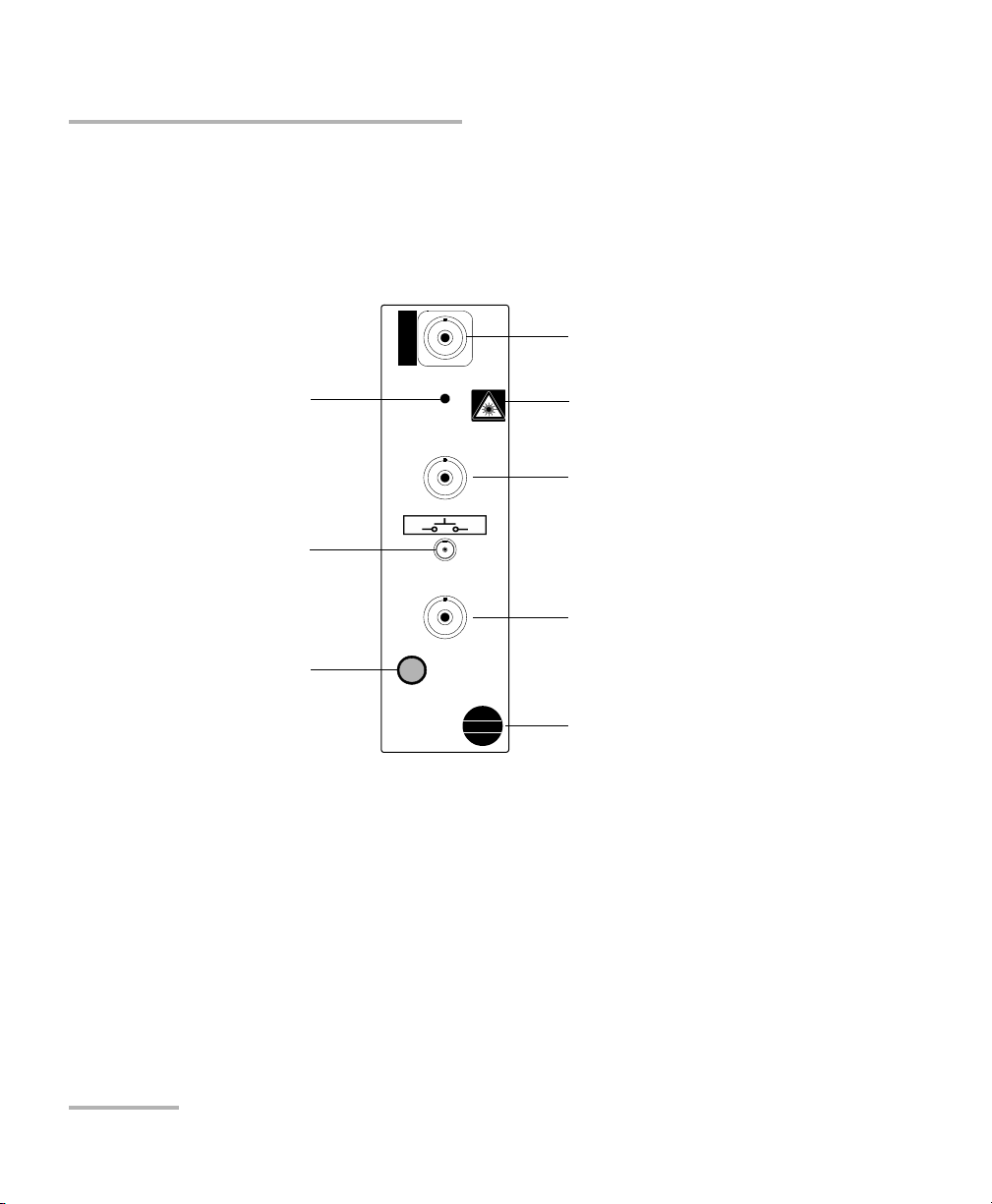
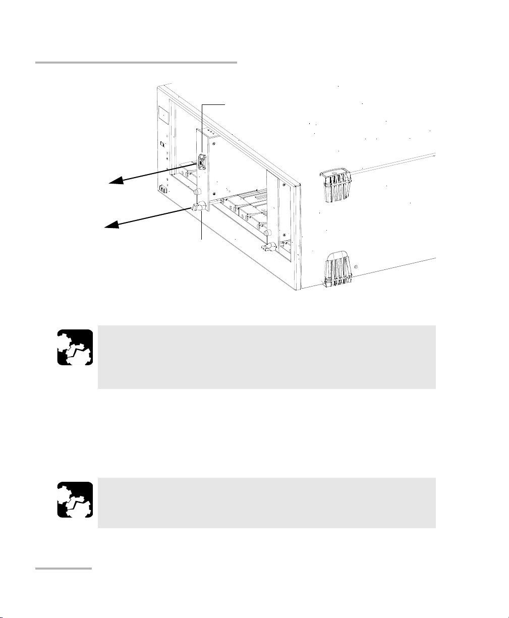
Introducing the IQS-2400 WDM Laser Source
Sync. in TTL port
Sync. out TTL port
Source port
Interlock connector
Laser radiation hazard sticker
(certain models only)
SYNC.
OUT
TTL
SYNC.
IN
TTL
ACTIVE
OUT
WDM Laser Source
IQS-2400
Retaining screw knob
Active LED
LED push button
Main Features
The IQS-2400 WDM Laser Source features wavelength tuning capabilities
for each of the ITU-T grid wavelengths, coherence control through a small
signal, and direct current modulation with a triangular or square
waveform. DFB laser diode manufacturers can also choose to integrate
their own lasers into the IQS-2400 WDM Laser Source.
Note: Actual connectors may differ from the ones shown above.
2 IQS-2400
Page 9

Introducing the IQS-2400 WDM Laser Source
Main Features
The IQS-2400 WDM Laser Source can operate in the following modes:
³ Normal mode provides access to total wavelength- and power-tuning
ranges, maintaining full control of the output power (automatic power
control).
³ High Wavelength Stability mode enables you to set wavelength and
power-tuning resolution with picometer accuracy through laser
temperature and current steps.
³ Dither Modulation mode adds a small waveform (triangular or square)
to the central wavelength signal, reducing the signal coherence length.
It provides modulation capabilities.
³ On/Off Modulation mode ensures maximum optical extinction and
make possible the synchronization of several sources from an external
TTL signal generator or from any module synchronization output. It
provides modulation capabilities.
WDM Laser Source 3
Page 10

Introducing the IQS-2400 WDM Laser Source
Safety Features
Safety Features
To comply with laser safety regulations, each IQS-2400 WDM Laser Source
is supplied with special security features.
Interlock Connector
The IQS-2400 WDM Laser Source is equipped with a remote interlock
connector so you can install a security switch or panic button. The WDM
Laser Source is shipped with an internally shorted interlock cap. It is your
responsibility to install external remote interlocks to ensure safe use of
your instrument.
The sticker is affixed to the front panel, just above the
interlock connector to identify it.
The interlock circuit has the following characteristics:
³ When it is open, the WDM Laser Source cannot be activated.
³ If the WDM Laser Source is active before the interlock circuit is
opened, it becomes inactive. For your safety, the WDM Laser Source
will not become active automatically upon closing the interlock circuit.
You will have to turn it on again. Putting the application’s switch to OFF
will shut down the instrument at any time.
The state of the interlock circuit (open or closed) is indicated in the WDM
Laser Source application.
4 IQS-2400
Page 11
Introducing the IQS-2400 WDM Laser Source
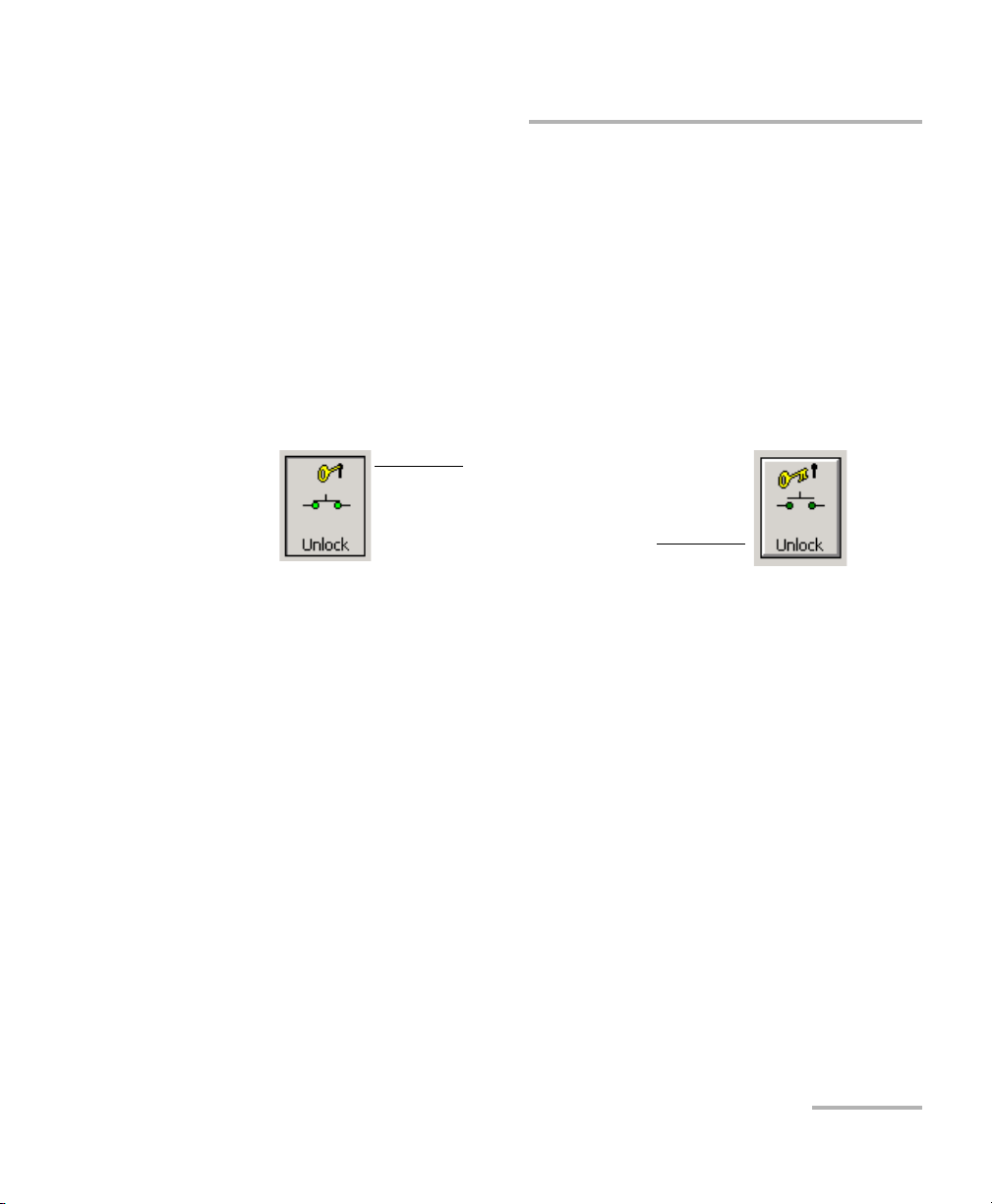
Instrument is unlocked:
Closed interlock icon
Instrument is locked:
Open interlock icon
Safety Features
Protection Software Key
For additional safety, you cannot activate the WDM Laser Source (with the
application ON/OFF switch) without unlocking it by entering the security
password “safekey”when prompted.
Note: This password cannot be changed and is the same for all instruments
requiring a software key.
Once the instrument has been unlocked, the Unlock button remains
pressed and the icon shows a closed interlock.
Five-Second Safety Delay
The IQS-2400 WDM Laser Source application provides a five-second safety
delay between the instrument activation and actual light emission. During
this five-second delay, you may cancel the activation of the laser by using
the instrument activation/deactivation switch, by opening the interlock
circuit or by using the software key button.
Note: The source emits a weak signal during the five-second delay.
WDM Laser Source 5
Page 12

Introducing the IQS-2400 WDM Laser Source
Typic a l A pp l icatio n s
Typical Applications
Because of its accuracy, you can use the IQS-2400 WDM Laser Source
instead of a wavelength measurement system when testing components
and subsystems.
The IQS-2400 WDM Laser Source emulates ITU-T channels in dense WDM
applications such as multiwavelength network simulation, simultaneous
multiple inputs for EDFA characterization, and insertion loss measurement
of WDM passive components. It is ideal for production environments and
offers unequaled long-term wavelength stability.
Place more than one IQS-2400 WDM Laser Source in an IQS Platforms and
obtain the versatility and reliability you need for optical fiber amplifier
testing and network qualification. In addition, with the IQS Platforms, you
can set up and control all of your modules at the same time.
You can customize your own high-performance test station by adding one
or several of the following modules to the WDM Laser Source: IQS-3100
Variable Attenuator, IQS-5100B Polarization Scrambler, IQS-5250B Optical
Spectrum Analyzer, IQS-9100 Optical Switch.
The IQS-2400 WDM Laser Source supports local control (via the
IQS Manager software) and remote control (through GPIB, RS-232, or
Ethernet TCP/IP using SCPI commands or the provided LabVIEW drivers).
For more information, refer to the IQS platform user guide.
6 IQS-2400
Page 13

Introducing the IQS-2400 WDM Laser Source
Conventions
Conventions
Before using the product described in this manual, you should understand
the following conventions:
WARNING
Indicates a potentially hazardous situation which, if not avoided,
could result in death or serious injury. Do not proceed unless you
understand and meet the required conditions.
CAUTION
Indicates a potentially hazardous situation which, if not avoided,
may result in minor or moderate injury. Do not proceed unless you
understand and meet the required conditions.
CAUTION
Indicates a potentially hazardous situation which, if not avoided,
may result in component damage. Do not proceed unless you
understand and meet the required conditions.
IMPORTANT
Refers to information about this product you should not overlook.
WDM Laser Source 7
Page 14

Page 15
2 Safety Information
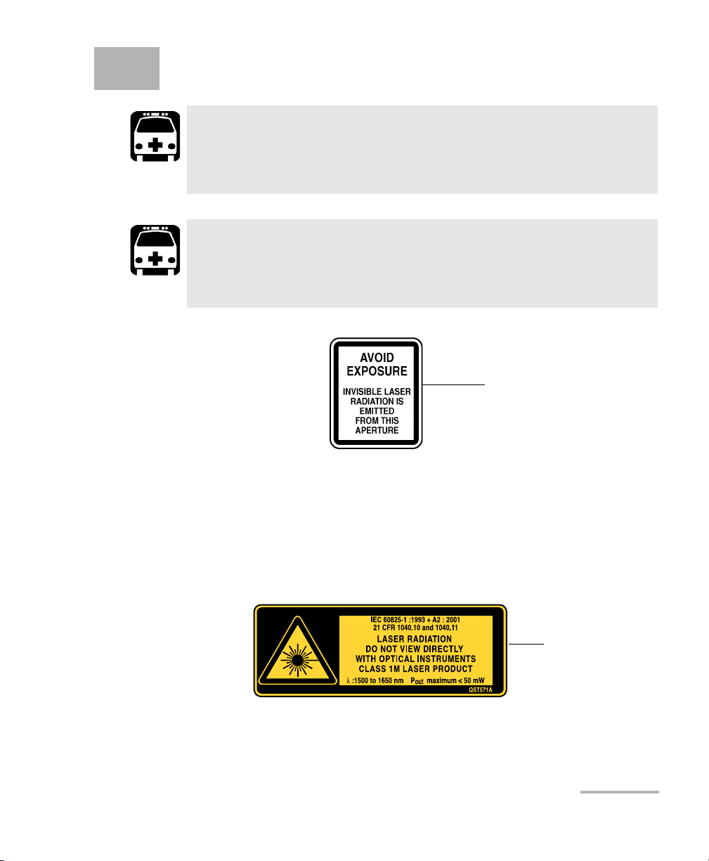
Affixed to module’s
side panel
Affixed to module’s
side panel
WARNING
Do not install or terminate fibers while a light source is active.
Never look directly into a live fiber and ensure that your eyes are
protected at all times.
WARNING
Use of controls, adjustments and procedures for operation and
maintenance other than those specified herein may result in
hazardous radiation exposure.
Your instrument is a Class 1M laser product in compliance with standards
IEC 60825-1 Amendment 2: 2001 and 21 CFR 1040.10. Invisible laser
radiation may be encountered at the output port.
The product is safe under reasonably foreseeable conditions of operation
but it may be hazardous if you use optics within a diverging or collimated
beam. Do not view directly with optical instruments.
WDM Laser Source 9
Page 16

Page 17
3 Getting Started with Your
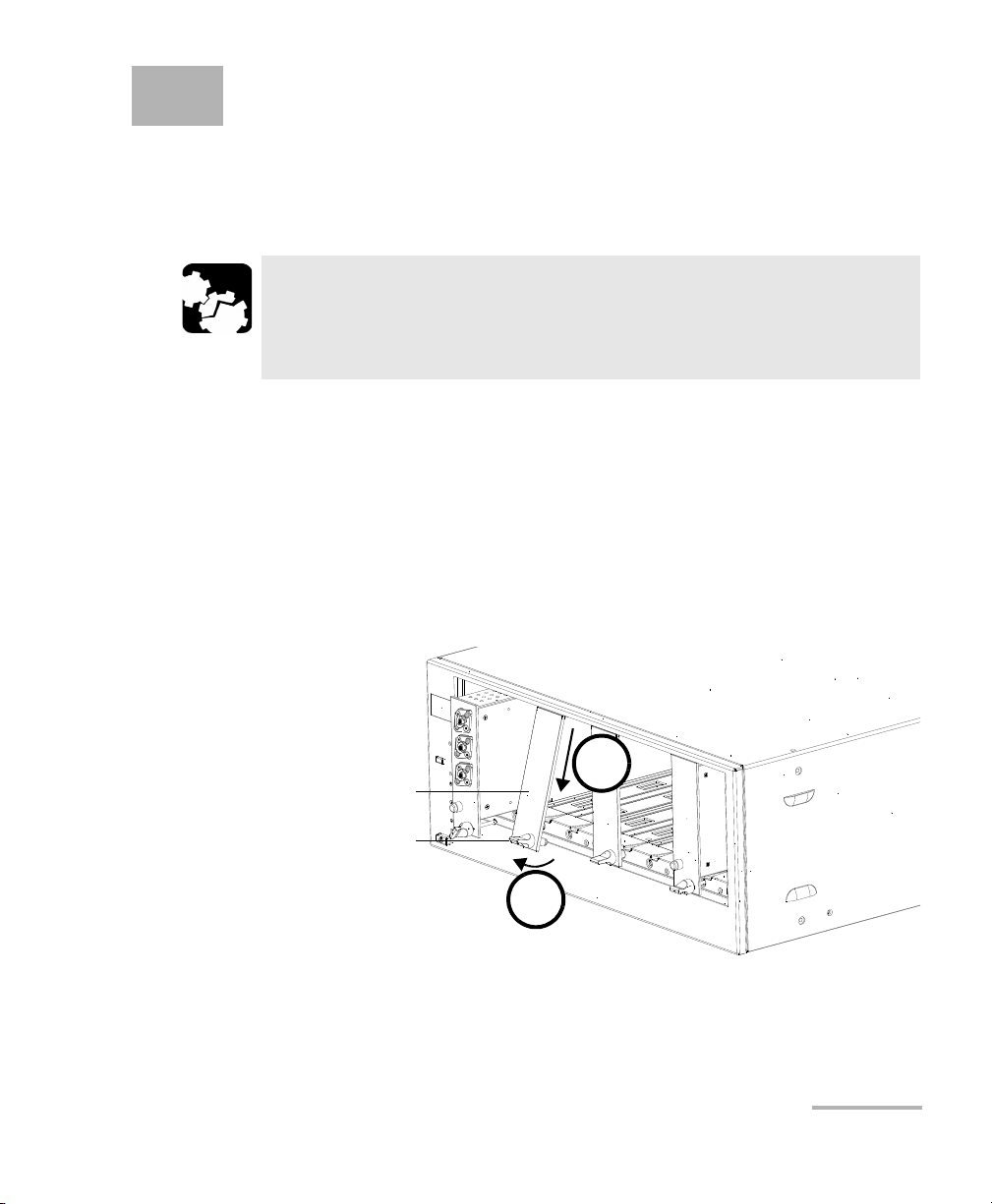
Retaining screw
knob
Protective cover
2b
2a
WDM Laser Source
Inserting and Removing Test Modules
CAUTION
Never insert or remove a module while the controller unit and its
expansion units are turned on. This will result in immediate and
irreparable damage to both the module and unit.
To insert a module into the controller or expansion unit:
1. Exit IQS Manager and turn off all your units.
2. Remove the protective cover from the desired unused module slot.
2a. Pull the retaining screw knob firmly towards you and release the
bottom of the cover.
2b. Gently pull the top of the protective cover downwards, to remove
it from the unit grooves.
3. Position the module so that its front panel is facing you and the top and
bottom protruding edges are to your right.
WDM Laser Source 11
Page 18
Getting Started with Your WDM Laser Source
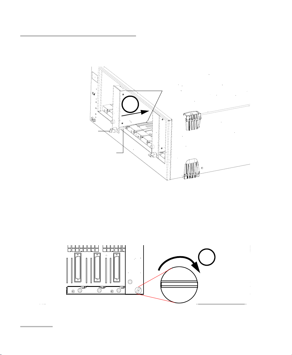
Retaining screw
Retaining screw knob
Protruding edges
(right side of module)
5
6
Inserting and Removing Test Modules
4. Insert the protruding edges of the module into the grooves of the unit’s
module slot.
5. Push the module all the way to the back of the slot, until the retaining
screw makes contact with the unit casing.
6. While applying slight pressure to the module, turn the retaining screw
knob (located at the bottom of the panel) clockwise until the knob is
horizontal.
This will secure the module into its “seated” position.
12 IQS-2400
Page 19
Getting Started with Your WDM Laser Source
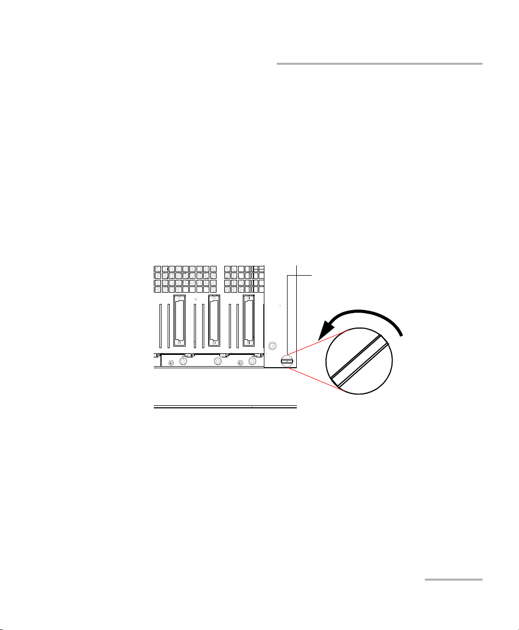
Retaining screw knob
Inserting and Removing Test Modules
The module is correctly inserted when its front panel is flush with the front
panel of the controller or expansion unit.
When you turn on the controller unit, the startup sequence will
automatically detect your module.
Note: You can insert IQ modules into your controller or expansion unit; the
IQS Manager software will recognize them. However, the IQS-2400 locking
mechanism (retaining screw) will not work for IQ modules.
To remove a module from your controller or expansion unit:
1. While pulling gently on the knob, turn it counterclockwise until it stops.
The module will slowly be released from the slot.
2. Place your fingers underneath the module or hold it by the retaining
screw knob (NOT by the connector) and pull it out.
WDM Laser Source 13
Page 20
Getting Started with Your WDM Laser Source
YES
NO
Retaining screw
knob
Connector
Inserting and Removing Test Modules
CAUTION
Pulling out a module by a connector could seriously damage both
the module and connector. Always pull out a module by the
retaining screw knob.
3. Cover empty slots with the supplied protective covers.
3a. Slide the top of the protective cover into the upper grooves of the
unit.
3b. Snap the cover into place by pushing the retaining screw knob.
Failure to reinstall protective covers over empty slots will result in
ventilation problems.
14 IQS-2400
CAUTION
Page 21
Getting Started with Your WDM Laser Source
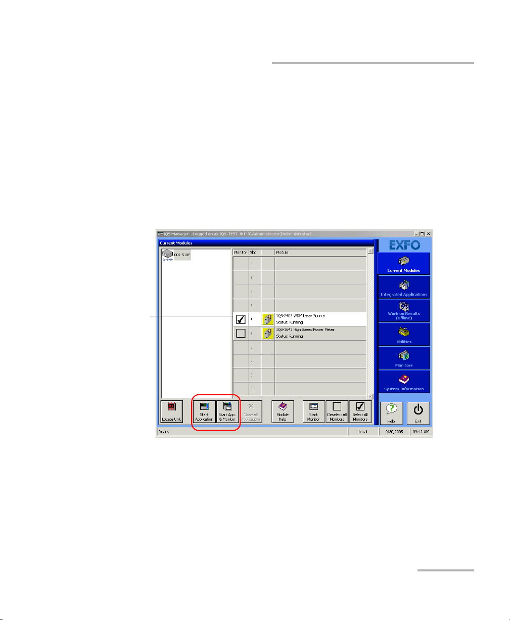
Highlighted
module
(white
background)
Starting the WDM Laser Source Application
Starting the WDM Laser Source Application
Your IQS-2400 WDM Laser Source module can be configured and
controlled from its dedicated IQS Managerapplication.
Note: For details about IQS Manager, refer to the IQS platform user guide.
To start the application:
1. From the Current Modules function tab select the module to use.
It will turn white to indicate that it is highlighted.
2. Click Start Application.
OR
Press the green LED push button on the front of the corresponding
module.
You can also double-click its row.
WDM Laser Source 15
Page 22
Getting Started with Your WDM Laser Source
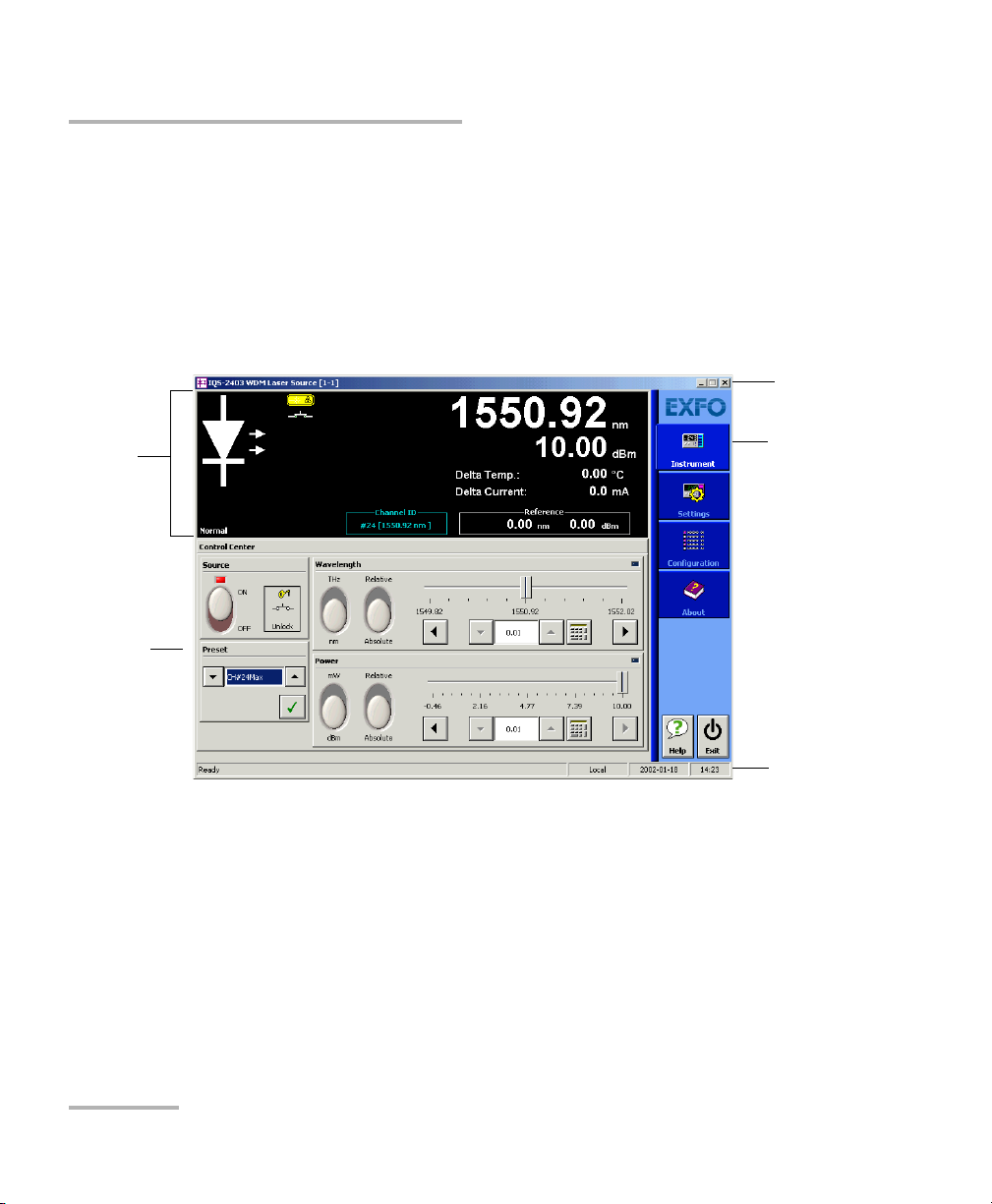
Function
tabs
Parameter
definition
controls
Data
display
Title bar
Status
bar
Starting the WDM Laser Source Application
Note: Pressing the LED push button will not activate or turn on the module.
Note: To start the corresponding monitor window at the same time, click Start
App. & Monitor. The window opens on the Monitors function tab.
The main window (shown below) contains all the commands required to
control the WDM Laser Source:
16 IQS-2400
Page 23
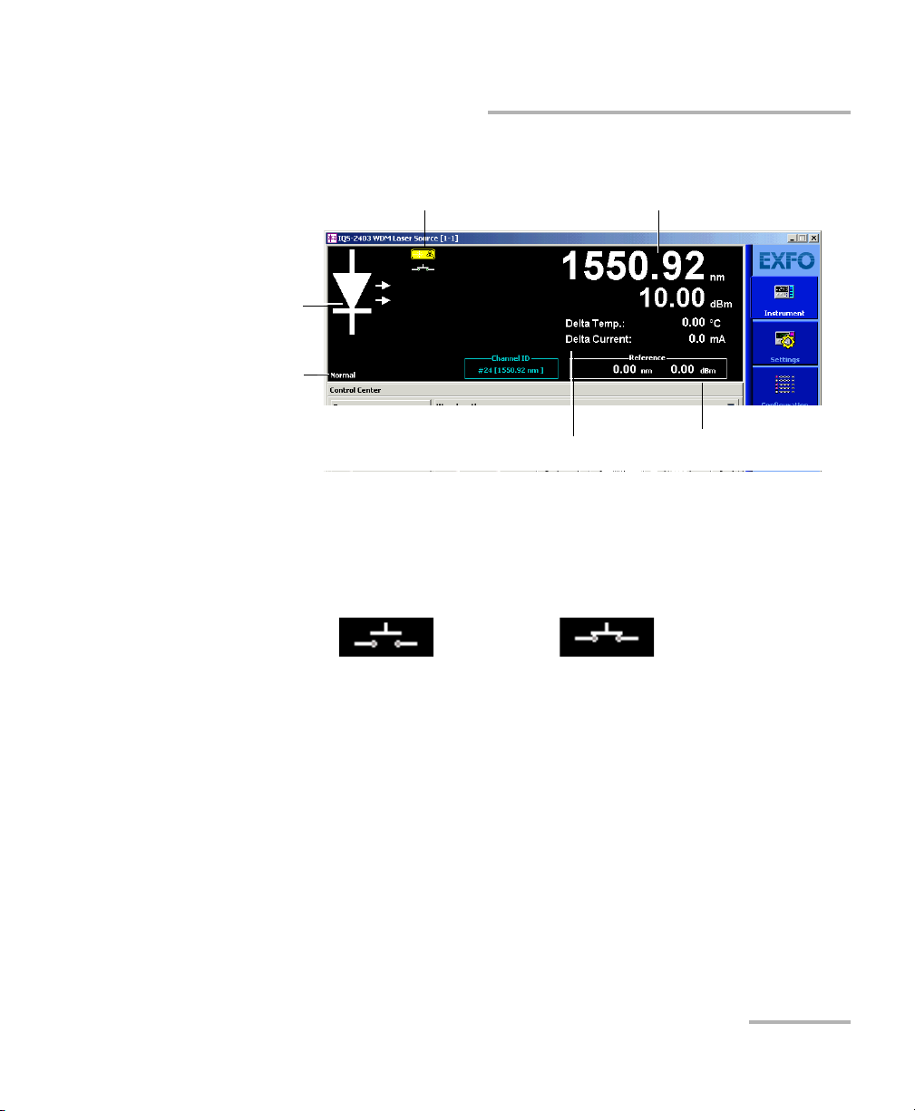
Getting Started with Your WDM Laser Source
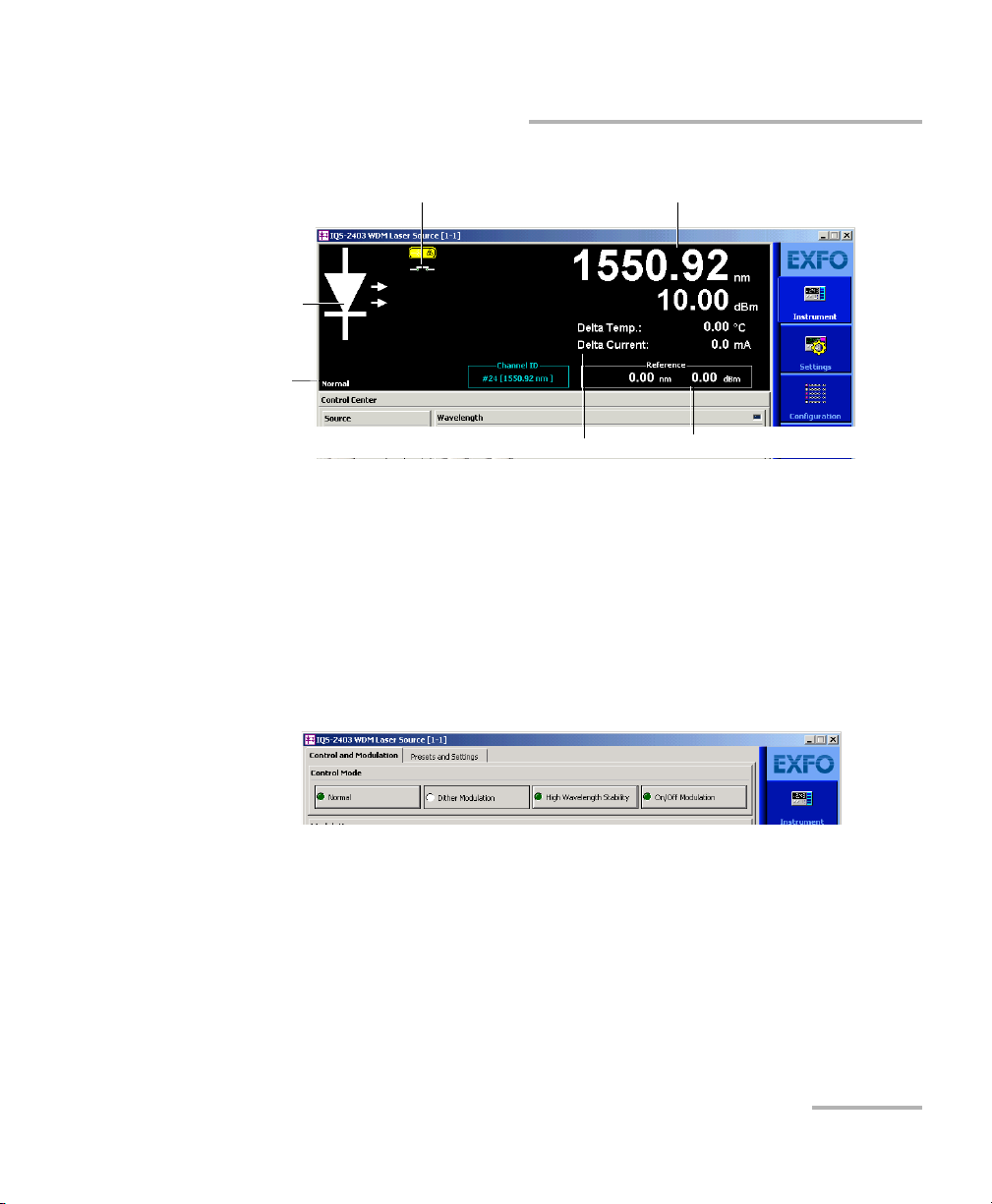
Source
control
mode
Source
status
indicator
Interlock circuit status indicator
Spectral and power values
Reference
values
Temperature and
current values
Open interlock circuit Closed interlock circuit
Starting the WDM Laser Source Application
Data Display
Depending on the setup, the displayed units (nm/THz, dBm/mW) will
change and some items may appear in bright colors or be grayed out.
The state of the interlock circuit (open or closed) is indicated by an icon, as
shown below:
WDM Laser Source 17
Page 24
Getting Started with Your WDM Laser Source
Slot number in which module is inserted
(0 identifies first slot)
Controller unit or expansion unit (1 to 999) housing
the module
[ 999 – 1 ]
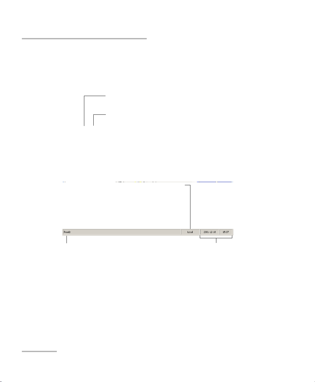
Current date and timeModule/unit status
Local: Module controlled locally only.
Remote: Module controlled remotely, but
local commands can also be used.
Lockout: Module controlled remotely only.
Control mode
Starting the WDM Laser Source Application
Title Bar
The title bar is located at the top of the main window. It displays the
module name and its position in the controller or expansion unit. The
module position is identified as follows:
Status Bar
The status bar, located at the bottom of the main window, identifies the
operational status of the IQS-2400 WDM Laser Source.
For more information about automating or remotely controlling the
IQS-2400 WDM Laser Source, refer to your platform user guide.
18 IQS-2400
Page 25
Getting Started with Your WDM Laser Source
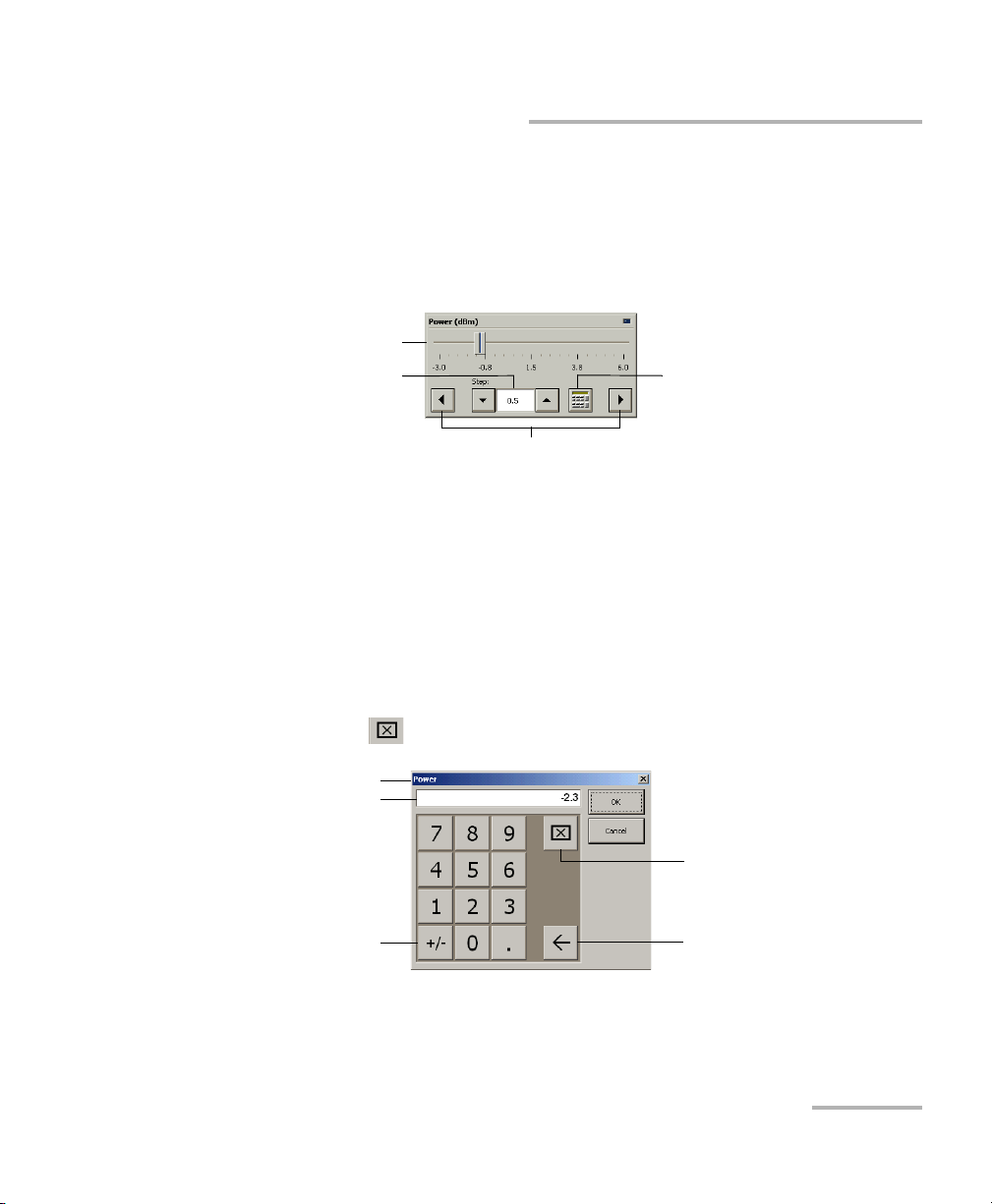
Numeric box
button
Fine-tuning
box
Slider
Navigation buttons
Parameter identification
Toggle button
Backspace button
(to correct a value)
Clear button
Entry display
Entering Values Using Sliders and Numeric Boxes
Entering Values Using Sliders and Numeric
Boxes
Many parameters in IQS Manager and module applications can be set
using the following tools.
³ Slider: Drag it to the desired value on the scale below.
³ Navigation buttons: Click either buttons to move the slider. The slider
moves by steps corresponding to the number in the fine-tuning box,
which you can change by using the up and down arrow buttons next to
the box. You cannot change the list of fine-tuning values from here.
³ Numeric box: Click it to display the on-screen numeric pad, which you
can use to enter a powe value.
WDM Laser Source 19
To enter a value using the numeric box:
1. Use the button to clear the entry display.
2. Enter the value.
3. Click OK to confirm the value.
Page 26

Getting Started with Your WDM Laser Source
Exiting the Application
Exiting the Application
Closing any application that is not currently being used is a good way to
free system memory.
To close the application from the main window:
Click in the top right corner of the main window.
OR
Click the Exit button located at the bottom of the function bar.
To close all currently running applications:
From IQS Manager, click Close All Applications.
20 IQS-2400
Page 27
4 Setting Up the WDM Laser
Source
Selecting a Control Mode
The IQS-2400 WDM Laser Source offers the following control modes:
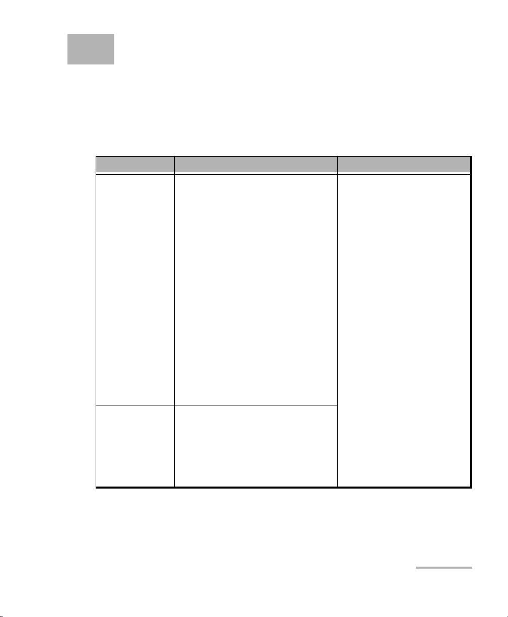
Mode Explanation Display
Normal ³ To maximize output power
stability.
³ Default mode used to tune
wavelength and power
throughout their respective
ranges (2 nm for wavelength
and 10 dB for power).
³ To maintain power at the
specified level, the monitor
current at the back end of the
laser will be held constant.
Laser current intensity is
adjusted in real time to
produce a constant output
power. Since peak wavelength
varies with laser current
intensity, the emission
spectrum is slightly enlarged.
Dither
Modulation
³ Combination of Normal mode
and dithering.
³ In this mode, you can have a
1 mA to 5 mA tone (dithering),
which can either be a square
or triangular wave.
During laser stabilization,
spectral value (wavelength
or frequency) and power are
displayed in dark green;
however, adjustments can
be made by using the
control center buttons. After
laser temperature
stabilization, both values are
displayed in light green.
For Norm a l m od e o nl y : if
you use Relative value,
reference values appear at
the bottom right-hand side
of the display (see
Configuring
Wavelength/Frequency or
Delta Temperature on page
29 and Configuring Power or
Delta Current on page 33).
WDM Laser Source 21
Page 28

Setting Up the WDM Laser Source
Selecting a Control Mode
Mode Explanation Display
High
Wa v el e ng t h
Stability
On/Off
Modulation
³ Used when central wavelength
stability is critical.
³ Current is constant, thus
maintaining wavelength
stability. Once power and
wavelength have been set to
the required levels (in Normal
mode), select High Wavelength
Stability mode to enhance
wavelength stability at the
established value. A limited
tuning range is permitted
around this value (± 1 °C for
wavelength or ± 1 mA for
current). Power stability can be
enhanced after a very long
stabilization period (typically 2
days).
³ This mode (50 % duty cycle)
uses half the average power
available from the source
module. It controls current
during the “on” cycle of the
signal.
³ The tuning range for
temperature and current are
the same as in High
Wavelength Stability mode.
Even though wavelength
and power are displayed in
light green, they cannot be
adjusted. Both modes are
used for fine-tuning laser
temperature and current on
a limited range around
nominal wavelength and
power levels reached in
Normal mode. Laser
temperature and current are
displayed just below the
power value.
22 IQS-2400
Page 29
Setting Up the WDM Laser Source
Source
control
mode
Source
status
indicator
Interlock circuit status indicator
Spectral and power values
Reference valuesTemperature and current values
Selecting a Control Mode
The spectral value shown on the data display is either the wavelength or
the frequency of the signal emitted. The spectral value corresponds to the
spectral unit you select in the main window. Wavelength values are given
in nm and frequency values in THz.
To select a control mode:
1. From the main window, select the Settings function tab.
2. Select the Control and Modulation tab.
3. From the Control Mode panel, select the desired control mode.
Note: You can modify the control mode while the laser is active. Changes to laser
operation will take effect immediately.
WDM Laser Source 23
Page 30

Setting Up the WDM Laser Source
Setting Modulation (for Dither and On/Off Modulation)
Setting Modulation (for Dither and On/Off
Modulation)
Modulation can be synchronized with a TTL signal coming from the
module itself (internal) or from another module (external). Default values
are Internal for synchronization and On/Off for modulation.
The module determines minimum and maximum frequencies.
For a dither modulation signal, you can select the depth and waveform of
the amplitude modulation signal added or overlapped over the CW signal.
The module's differential efficiency determines minimum and maximum
depths.
To set up the modulation:
1. From the main window, select the Settings function tab.
2. Select the Control and Modulation tab.
3. For the On/Off control mode, select the source synchronization mode:
internal or external from the Synchronization section.
Note: Synchronization can only be internal with Dither Modulation control mode.
24 IQS-2400
Page 31

Setting Up the WDM Laser Source
Current
frequency
Fine-tuning values
Setting Modulation (for Dither and On/Off Modulation)
4. From the Frequency section, if you have selected internal
synchronization, you can adjust the modulation frequency of the laser
signal emitted by the source. For information on how to use the
controls, see Entering Values Using Sliders and Numeric Boxes on
page 19.
Note: You cannot edit fine-tuning values or add new values.
5. If you have selected the Dither Modulation control mode, you can
configure depth and waveform of the modulation signal as follows:
5a. Select the desired waveform (square or triangular) from the
Waveform panel.
5b. Specify the desired modulation signal depth with the Depth
controls.
Note: You cannot edit fine-tuning values or add new values.
WDM Laser Source 25
Page 32

Setting Up the WDM Laser Source
Configuring Wavelength/Frequency or Delta Temperature
Configuring Wavelength/Frequency or Delta
Temperature
Values appearing on the display correspond to:
³ the actual value obtained in Normal or Dither Modulation modes at
selected wavelength
OR
³ the delta temperature (difference between the above value and the
temperature obtained after switching to High Wavelength Stability or
On/Off Modulation modes).
Adjustable parameters depend on the control mode:
³ Normal and Dither modes: to adjust the spectral value (wavelength or
frequency). Relative value is only available for these modes.
³ High Wavelength Stability and On/Off Modulation modes: once you
have set the wavelength in Normal mode or Dither, you can use these
modes to enhance wavelength stability at the established value
(permitted tuning range: ±1 °C).
³ In all modes, modifying the wavelength or frequency also modifies the
internal laser temperature. The source will then take a few seconds to
adjust to the new value.
26 IQS-2400
Page 33

Setting Up the WDM Laser Source
Spectral and power values
Temperature and current values
(only displayed in High Wavelength Stability
and On/Off Modulation modes)
Stabilization
message
Wavelength/
frequency
selection
Presets list
Relative/absolute value selection
Configuring Wavelength/Frequency or Delta Temperature
The main window data display differs for each control mode.
To configure wavelength/frequency in (Normal or Dither
Modulation modes only):
1. If you want to display the source wavelength, select nm. If you want to
display the frequency, select THz.
WDM Laser Source 27
Page 34

Setting Up the WDM Laser Source
Configuring Wavelength/Frequency or Delta Temperature
2. Select between Relative and Absolute values.
Selecting the relative value will make the current wavelength or
frequency the reference value. The new value shown on the data
display corresponds to the difference between the reference value and
the actual value.
3. Set the wavelength/frequency using one of the following methods:
³ Slider or navigation buttons
³ Up/down arrows to select the predefined parameters from the
Presets list and to confirm the selection. For more information,
see Managing Predefined Parameters (Presets) on page 34.
The source takes a few seconds to adjust to the selected values; a message
will be displayed on the left, just above the current source mode.
28 IQS-2400
Page 35

Setting Up the WDM Laser Source
Presets list
Delta temperature control
Configuring Wavelength/Frequency or Delta Temperature
To configure the delta temperature (wavelength) in High
Wavelength Stability or On/Off Modulation modes:
Set the delta temperature using one of the following methods:
³ Slider or navigation buttons
³ Up/down arrows to select the predefined parameters from the Presets
list and to confirm the selection. For more information, see
Managing Predefined Parameters (Presets) on page 34.
The source takes a few seconds to adjust to the selected values, a message
will be displayed on the left, just above the current source mode.
WDM Laser Source 29
Page 36

Setting Up the WDM Laser Source
Configuring Power or Delta Current
Configuring Power or Delta Current
Values appearing on the display correspond to:
³ the actual value on the source port obtained in Normal and Dither
Modulation modes at selected wavelength
OR
³ the delta obtained after switching to High Wavelength Stability and
On/Off modes).
Adjustable parameters depend on the control mode:
³ Normal and Dither modes: to adjust the source power. Relative value is
only available for these modes.
³ High Wavelength Stability and On/Off Modulation modes: once you
have set the desired power in Normal mode, you can use these modes
to enhance wavelength stability at the established value (permitted
tuning range: ±1 mA for temperature/wavelength).
³ In all modes, modifying the power current also modifies the internal
laser temperature. The source then takes a few seconds to adjust to
the new value and a message will be displayed.
The main window data display differs for each control mode.
30 IQS-2400
Page 37

Setting Up the WDM Laser Source
Power unit Relative/absolute
value selection
Power panel control
Presets list
Configuring Power or Delta Current
To configure the source power in Normal or Dither Modulation
mode:
1. Select dBm or mW to modify the power units used in the data display.
2. Select between Relative and Absolute values. Selecting Relative value
will make the current power the reference value. The new value
shown corresponds to the difference between the reference value and
the actual value. For more information, see Configuring Power or Delta
Current on page 30.
3. Set the power using one of the following methods:
³ Slider or navigation buttons
³ Up/down arrows to select the predefined parameters from the
Presets list and to confirm the selection. For more information,
see Managing Predefined Parameters (Presets) on page 34.
The source will take a few seconds to adjust to the selected values, a
message will be displayed on the left, just above the current source mode.
WDM Laser Source 31
Page 38

Setting Up the WDM Laser Source
Delta current
control
Presets list
Configuring Power or Delta Current
To configure the source delta current in High Wavelength
Stability or On/Off Modulation mode:
Set the delta current using one of the following methods:
³ Slider or navigation buttons
³ Up/down arrows to select the predefined parameters from the
Presets list and to confirm the selection. For more information,
see Managing Predefined Parameters (Presets) on page 34.
The source takes a few seconds to adjust to the selected values, a message
will be displayed on the left, just above the current source mode.
32 IQS-2400
Page 39

Setting Up the WDM Laser Source
Entry box
Delete button
Apply button
Managing Fine-Tuning Values
Managing Fine-Tuning Values
Fine-tuning values are the increments (steps) used in Normal and Dither
Modulation modes to increase or decrease (with the navigation buttons or
slider):
³ signal wavelength or frequency in nm or THz.
³ power emitted by the source in dB or mW (Values are not converted
from one unit to the other).
Values can appear differently depending on the unit you select.
Note: Fine-tuning values are not available in High Wavelength Stability or in
On/Off Modulation modes since settings are made on delta temperature.
To add a new increment value:
1. Select the Settings function tab.
2. In the New Value box, enter the desired value.
3. Use to transfer the new value to the list.
To delete a value from the list:
1. Select the item to delete.
2. Use to remove the value from the list.
WDM Laser Source 33
Page 40

Setting Up the WDM Laser Source
Managing Predefined Parameters (Presets)
Managing Predefined Parameters (Presets)
A preset is a set of parameters that you can use to configure the source in a
single operation. Presets are especially useful when you often need to set
the source to specific parameters.
Note: In Dither Modulation or On/Off Modulation modes, the application will not
retain any modulation information. Saved parameters are only related to
wavelength and power (actual values or delta temperature/current).
Control mode Parameters defined by presets
Normal
Dither
Modulation
High
Wa v el e ng t h
Stability
On/Off
Modulation
Presets list contains default values (defined by EXFO and calibrated at the
wavelength specified at time of purchase) and user-defined values. Each
preset is saved under a specific name. Presets appear on a list in the main
window.
You can remove or rename any preset from the list, except the default
ones.
³ power
³ minimum, central and maximum wavelength
³ power
³ central wavelength
³ relative laser temperature (difference between absolute
temperature and actual value)
³ relative drive current (difference between absolute
current and actual value)
IMPORTANT
To create a preset, the laser must be on and stabilized.
34 IQS-2400
Page 41

Setting Up the WDM Laser Source
Apply button
Delete button
Managing Predefined Parameters (Presets)
To create a preset:
1. Select a control mode, as explained in Selecting a Control Mode on
page 21.
2. Adjust source wavelength and power to the desired levels.
For more information, see Configuring Wavelength/Frequency or Delta
Tem pe ra tu re on page 26 and Configuring Power or Delta Current on
page 30.
3. Select the Presets and Settings tab from the Settings function tab.
4. Use the Add Current Settings button to transfer the current source
settings to a new preset.
5. Enter a name for the preset (max. 10 characters) and add it to the list
with . You can also discard the new preset with .
6. The new set of values becomes the active preset and is displayed in
the main window.
Note: You should select a significant name to facilitate further usage of the preset.
For example, identify the new preset by its wavelength (for
example,1552.23) or give it the name of the signal destination (for
example,Channel_1).
WDM Laser Source 35
Page 42

Setting Up the WDM Laser Source
Managing Predefined Parameters (Presets)
To rename a preset:
1. Select the Presets and Settings tab from the Settings function tab.
2. Select the preset to be renamed and use the Rename Preset button to
edit the name.
3. Enter the new name.
4. Confirm the modification by using .
To delete a preset:
1. Select the Presets and Settings tab from the Settings function tab.
2. Select the preset to remove.
3. Use the Remove From List button to delete the item.
36 IQS-2400
Page 43

Setting Up the WDM Laser Source
To save parameters being used
just before shutting down,
overwriting the previous file.
To always use the last saved
parameters when starting.
Saving and Recalling Configurations
Saving and Recalling Configurations
Once you have set the IQS-2400 WDM Laser Source parameters, you can
save your custom configuration and recall it at any time. You can also recall
the factory-defined settings.
Saved configurations include all parameters set in the Control Center
(Instrument function tab) and in the Settings function tab (if present).
To save a configuration:
1. Select the Configuration function tab.
2. In the Current Module Configuration panel, enter the name you wish
to use for your configuration file.
It will be saved in
“D:\IQS Manager\Configuration Files\(your_module)\”.
3. Click Save.
WDM Laser Source 37
Page 44

Setting Up the WDM Laser Source
Saving and Recalling Configurations
To recall a configuration:
1. Select the Configuration function tab.
2. Click Open.
3. Select the configuration file you wish to recall and confirm your action.
You are returned to the application and the new parameters are set.
To revert to factory settings:
1. Select the Configuration function tab.
2. Click the Reset Module to Factory Settings button.
Reverting to the factory settings will interrupt any module
operation in progress.
The operation may take a few seconds to complete.
IMPORTANT
IMPORTANT
38 IQS-2400
Page 45

5 Operating the WDM Laser
Source
Cleaning and Connecting Optical Fibers
IMPORTANT
To ensure maximum power and to avoid erroneous readings:
³ Always clean fiber ends as explained below before inserting
them into the port. EXFO is not responsible for damage or
errors caused by bad fiber cleaning or handling.
³ Ensure that your patchcord has appropriate connectors. Joining
mismatched connectors will damage the ferrules.
To connect the fiber-optic cable to the port:
1. Clean the fiber ends as follows:
1a. Gently wipe the fiber end with a lint-free swab dipped in isopropyl
alcohol.
1b. Use compressed air to dry completely.
1c. Visually inspect the fiber end to ensure its cleanliness.
2. Carefully align the connector and port to prevent the fiber end from
touching the outside of the port or rubbing against other surfaces.
If your connector features a key, ensure that it is fully fitted into the
port’s corresponding notch.
3. Push the connector in so that the fiber-optic cable is firmly in place,
thus ensuring adequate contact.
If your connector features a screwsleeve, tighten the connector
enough to firmly maintain the fiber in place. Do not overtighten, as this
will damage the fiber and the port.
Note: If your fiber-optic cable is not properly aligned and/or connected, you will
notice heavy loss and reflection.
WDM Laser Source 39
Page 46

Operating the WDM Laser Source
Bare metal
(or blue border)
indicates UPC
option
Green border
indicates APC
option
2 3 4
Installing the EXFO Universal Interface (EUI)
Installing the EXFO Universal Interface (EUI)
The EUI fixed baseplate is available for connectors with angled (APC) or
non-angled (UPC) polishing. A green border around the baseplate
indicates that it is for APC-type connectors.
To install an EUI connector adapter onto the EUI baseplate:
1. Hold the EU connector adapter so the dust cap opens downwards.
2. Close the dust cap in order to hold the connector adapter more firmly.
3. Insert the connector adapter into the baseplate.
4. While pushing firmly, turn the connector adapter clockwise on the
baseplate to lock it in place.
40 IQS-2400
Page 47

Operating the WDM Laser Source
Indicates that
the WDM Laser
Source is locked
Activating and Deactivating the Source
Activating and Deactivating the Source
This section gives you all the information required to activate and
deactivate the source. For more information on the particular safety
features, see Safety Features on page 4.
IMPORTANT
To obtain optimum stability, warm up your laser source for 60
minutes once it has been activated.
To activate the WDM Laser Source:
1. Make sure that the interlock connector (located on the instrument
front panel) is closed.
Note: Since the interlock circuit is a mechanical device, it cannot be opened or
closed via the application.
2. If the WDM Laser Source is locked, you will have to unlock it with the
software key button (Unlock button). This button displays an open
interlock when the instrument is locked.
If necessary, use the Unlock button. When prompted, enter the
password “safekey”.
Note: Using the Unlock button when the instrument is unlocked will
automatically stop light emission.
WDM Laser Source 41
Page 48

Operating the WDM Laser Source
Source
status
indicator
Interlock circuit status indicator
Activating and Deactivating the Source
3. From the Instrument function tab, set the Source switch to ON.
The status indicator flashes during the five-second safety delay. When
the source is active, the LED on the module front panel lights up and
the status indicator appears in bright red with two right-pointing
arrows.
To deactivate the WDM Laser Source:
³ Put the activation/deactivation switch to Off.
OR
³ Use the Unlock button. This ensures that you will need to enter a
password again when you reactivate the instrument.
Once the source has been deactivated, the LED on the module front panel
turns off, the status indicator appears in dark red and the arrows disappear.
42 IQS-2400
Page 49

Operating the WDM Laser Source
Correcting the Output Power Level
Correcting the Output Power Level
Although the module is precisely calibrated, the actual output power level
may slightly drift over time due to connector usage and laser aging. When
this occurs, you can use the power calibration option to adjust the output
power level to its actual value, as measured using a calibrated power
meter.
Correcting the source output power level is only possible in Normal mode.
If you are controlling multiple IQS-2400 WDM Laser Source modules, you
will have to adjust each source output power level individually (use the
Control Single Instrument button to switch to the appropriate tab).
To correct the output power level:
1. Use a reference patchcord with a known insertion loss and make sure
it has been properly cleaned at both ends.
2. Connect the patchcord between a calibrated power meter and the
source port.
3. Make sure you activated the source at least one hour before correcting
the output power level. For more information, see Activating and
Deactivating the Source on page 41.
WDM Laser Source 43
Page 50

Operating the WDM Laser Source
Apply button
Calibration
instructions
Correcting the Output Power Level
4. Select the Settings function tab, then select the presets and settings
tab.
5. From the Power Calibration panel, follow the instructions displayed.
Once you have entered the value, confirm with . The "User
Calibration" label will appear on the left side of the Instrument
function tab data display.
The new power level is used as a reference to reestablish the
correspondence between the output power level and the displayed
values.
Use the Factory Calibration button to return to EXFO’s original
calibration at any time. The "User Calibration" label will disappear from
the Instrument function tab display.
44 IQS-2400
Page 51

Operating the WDM Laser Source
Synchronizing Sources
Synchronizing Sources
You can use synchronization to simultaneously perform operations
(for example, wavelength adjustments) on many IQS-2400 WDM Laser
Source modules. The sources can be synchronized with a signal coming
from an external instrument or from an other IQS-2400 WDM Laser Source.
To synchronize your source module with another instrument:
1. Connect a BNC cable from
³ the external device to the Sync. In TTL port of the first source
module.
OR
³ the Sync. Out port of the synchronizing IQS-2400 WDM Laser
Source to the Sync. In TTL port of the sources to be synchronized.
2. Use a BNC-T connector between each Sync. In port if more than one
source needs to be synchronized.
WDM Laser Source 45
Page 52

Page 53

6 Controlling Multiple WDM
Laser Source Modules
With your platform, you can set common parameters and simultaneously
operate several modules of the same kind in a single interface, which is
particularly useful in larger systems.
Note: You should be familiar with the configuration and operation of a single
module before controlling multiple modules simultaneously.
Starting a Multimodule Application
The multimodule applications available will change according to your
module configuration (model, type, etc.).
Note: When you start a multimodule application, you cannot open a monitor
window at the same time, as it is possible with a single-module
application. You must open the monitor window independently.
To start a multimodule application:
1. In IQS Manager, select the Integrated Applications function tab.
2. Click the appropriate Multiple Module Controller button.
The multimodule application appears in a new window.
Note: More than one Multiple Module Controller button may be displayed if
different models are present in your platform.
WDM Laser Source 47
Page 54

Controlling Multiple WDM Laser Source Modules
Specific
module
selection
All
modules
selection
Selecting Modules to Control
Selecting Modules to Control
Before you can modify the module parameters, you must specify which
modules you intend to use.
To select IQS-2400 WDM Laser Source modules:
1. On the Modules/Config function tab, select the boxes corresponding
to the modules you want to control.
OR
Click Select All if you want to work with all IQS-2400 WDM Laser
48 IQS-2400
Source modules.
2. Click Apply Selections and click the Instruments function tab.
Page 55

Controlling Multiple WDM Laser Source Modules
Parameter
definition
controls
Single
source mode
Selected
module
indicator
Master control indicator (open lock: on; closed
lock: off). See Protection Software Key on page 5.
Information appears in red during
source stabilization
Source
Status
Setting Up Multiple IQS-2400 WDM Laser Source Modules
Setting Up Multiple IQS-2400 WDM Laser
Source Modules
Principles that rule the performance of your IQS-2400 WDM Laser Source
are the same whether you control one or many sources at the same time.
For information, see Wavelength and Power Control, General Principles on
page 183.
All parameters that can be set for a single module can also be set for
multiple modules, except for preset values (because source characteristics
may vary from one module to another). In fact, all the settings must be
WDM Laser Source 49
made with offset values.
Page 56

Controlling Multiple WDM Laser Source Modules
Apply button
Control
modes
Setting Up Multiple IQS-2400 WDM Laser Source Modules
IMPORTANT
Before setting parameters or turning sources on, make sure that
their corresponding boxes are selected.
To modify a particular parameter (all are set the same way):
1. Select the tab associated with the parameter to be modified.
2. Use the and buttons to define the value that will be added to the
parameter value. If you want to decrease the parameter value, make
sure that the offset is negative.
Note: You can modify the step used when you increase or decrease the offset
value. Use the Offset Step up/down arrows to modify the step.
3. When you are satisfied with the offset value, use to confirm the new
setting.
Note: If the new offset value is out of the permitted range, the application displays
an error message.
To set the control mode:
For information, see Selecting a Control Mode on page 21.
50 IQS-2400
Page 57

Controlling Multiple WDM Laser Source Modules
Modulation parameter controls
Wavelength parameter controls
Setting Up Multiple IQS-2400 WDM Laser Source Modules
To set modulation:
For information, see Setting Modulation (for Dither and On/Off Modulation)
on page 24.
To set wavelength/frequency:
Wavelength or frequency will be used with Normal and Dither Modulation
modes. With the Quick Settings buttons, you can directly set the source
wavelength values to their intrinsic Maximum, Central or Minimum value.
For information, see Configuring Wavelength/Frequency or Delta
Tem pe ra tu re on page 26.
WDM Laser Source 51
Page 58

Controlling Multiple WDM Laser Source Modules
Power parameter controls
Delta temperature parameter controls
Setting Up Multiple IQS-2400 WDM Laser Source Modules
To s et p ow er :
Power will be used with Normal and Dither Modulation modes. With the
Quick Settings buttons, you can directly set the source power value to their
intrinsic Maximum or Minimum value.
For information, see Configuring Power or Delta Current on page 30.
To set delta temperature:
Delta temperature will be used with High Wavelength Stability and On/Off
Modulation modes.
For information, see Configuring Wavelength/Frequency or Delta
Tem pe ra tu re on page 26.
52 IQS-2400
Page 59

Controlling Multiple WDM Laser Source Modules
Delta current parameter controls
Controlling a Single IQS-2400 WDM Laser Source
To set delta current:
Delta current will be used with High Wavelength Stability and On/Off
Modulation modes.
For information, see Configuring Power or Delta Current on page 30.
Controlling a Single IQS-2400 WDM Laser
Source
You may want to control a specific module among all the IQS-2400 WDM
Laser Source modules that you have in the system.
To control a specific IQS-2400 WDM Laser Source:
1. Make sure that the row corresponding to the module you want to
control appears in bold or that it is highlighted.
2. Use the Control Single Instrument button to open the IQS-2400 WDM
Laser Source application.
WDM Laser Source 53
Page 60

Controlling Multiple WDM Laser Source Modules
IQS Manager - Integrated
Applications (Multi-modules)
Your module main application
window (single module)
Your module Multiple Module
Controller - Instruments tab
Your module Multiple Module
Controller - Modules/Config tab
Open
Apply Selections
Control Single
Instrument
Exit
Exit
Navigating and Closing Multiple Module Windows
Navigating and Closing Multiple Module
Windows
When controlling multiple modules, a number of windows are open at the
same time. To close a window, use the Exit button located under the
function tabs. You will return to the preceding window.
The following diagram illustrates the navigation between windows:
54 IQS-2400
Page 61

7 Monitoring WDM Laser Source
Modules
When using your IQS-2400 WDM Laser Source module, either alone or
with other modules in a test setup, you can view module data and status
using its monitor window in IQS Manager.
Using Monitor Windows
Monitor windows display basic data about modules. A combination of
resizable windows allows you to create an integrated data display (refer to
the platform user guide).
From the monitor window, you can change module parameters either by:
³ opening the module application to access all the functions
OR
³ using the QuickTools utility, which provides frequently used functions
from the application.
WDM Laser Source 55
Page 62

Monitoring WDM Laser Source Modules
Selected modules
(checked)
Using Monitor Windows
To select modules and display their monitor windows:
1. On the Current Modules function tab, select the controller or
expansion unit containing the modules you want to monitor.
2. In the Monitor column, select the box next to each module you want
to monitor.
If you want to monitor all the modules in the current unit, click Select
All Monitors. If you want to clear your choices, click Deselect All
Monitors.
56 IQS-2400
Page 63

Monitoring WDM Laser Source Modules
Close
button
Rearrange
Monitors
button
(1 or 2
columns)
Monitor window
arrow buttons
Close All
button
Using Monitor Windows
3. Click Start Monitor to apply your selection.
IQS Manager will display the selected monitor windows on the
Monitors function tab.
Note: To start t he highlighted module’s corresponding application at the same
time, click Start App. & Monitor. The application will appear in a different
window.
WDM Laser Source 57
Page 64

Monitoring WDM Laser Source Modules
Using QuickTools
Using QuickTools
With QuickTools, you can fine-tune your module directly, while keeping an
eye on your entire test setup.
Note: You can only access QuickTools if the module’s monitor window is selected
from the Monitors function tab and is currently active.
To start QuickTools:
1. From the Monitors function tab, elect the monitor window of the
module you wish to control.
2. Using the arrow button in the upper left corner, select QuickTools.
The corresponding monitor window flashes when QuickTools is
activated.
Note: If you want to open the actual application for your module rather than
QuickTools, click Show Controller.
58 IQS-2400
Page 65

Monitoring WDM Laser Source Modules
Using QuickTools
To control a specific source with QuickTools:
1. Ensure that the source monitor window is selected.
2. Select the appropriate control mode. For a full explanation on control
modes, see Selecting a Control Mode on page 21.
3. From the Wavelength section, adjust the wavelength as follows:
3a. If the control mode is Normal or Dither Modulation, select
between frequency (THz) and wavelength (nm).
3b. Adjust the value and confirm your settings.
4. From the Power section, adjust the power as follows:
4a. If the control mode is Normal or Dither Modulation, select the unit
in which you want the values to be expressed: mW or dBm.
4b. Adjust the value and confirm your settings.
5. Unlock the source and turn it on. For more information, see Activating
and Deactivating the Source on page 41.
Note: Preset values are not available from the QuickTools utility.
To c lo s e Q ui c kTo o l s :
³ Click the Close button located at the top of the window.
OR
³ Click outside the QuickTools window.
To close a monitor window:
Click the button on the upper left of the monitor window and select
Remove Monitor.
OR
Click the Close All button at the bottom of the window.
WDM Laser Source 59
Page 66

Page 67

8 Maintenance
To help ensure long, trouble-free operation:
³ Always clean fiber-optic connectors before using them.
³ Keep the unit free of dust.
³ Clean the unit casing and front panel with a cloth slightly dampened
with water.
³ Store unit at room temperature in a clean and dry area. Keep the unit
out of direct sunlight.
³ Avoid high humidity or significant temperature fluctuations.
³ Avoid unnecessary shocks and vibrations.
³ If any liquids are spilled on or into the unit, turn off the power
immediately and let the unit dry completely.
Use of controls, adjustments, and procedures for operation and
maintenance other than those specified herein may result in
hazardous radiation exposure.
WARNING
WDM Laser Source 61
Page 68

Maintenance
Cleaning Fixed Connectors
Cleaning Fixed Connectors
Regular cleaning of connectors will help maintain optimum performance.
Do not try to disassemble the unit. Doing so would break the connector.
To clean fixed connectors:
1. Fold a lint-free wiping cloth in four to form a square.
2. Moisten the center of the lint-free wiping cloth with only one drop of
isopropyl alcohol.
Alcohol may leave traces if used abundantly. Avoid contact between
the tip of the bottle and the wiping cloth, and do not use bottles
that distribute too much alcohol at a time.
3. Gently wipe the connector threads three times with the folded and
moistened section of the wiping cloth.
IMPORTANT
IMPORTANT
Isopropyl alcohol takes approximately ten seconds to evaporate.
Since isopropyl alcohol is not absolutely pure, evaporation will
leave microscopic residue. Make sure you dry the surfaces before
evaporation occurs.
4. With a dry lint-free wiping cloth, gently wipe the same surfaces three
times with a rotating movement.
5. Throw out the wiping cloths after one use.
6. Moisten a cleaning tip (2.5 mm tip) with only one drop of isopropyl
alcohol.
62 IQS-2400
Page 69

Maintenance
7
8
9
Cleaning Fixed Connectors
IMPORTANT
Alcohol may leave traces if used abundantly. Avoid contact between
the tip of the bottle and the cleaning tip, and do not use bottles
that distribute too much alcohol at a time.
7. Slowly insert the cleaning tip into the connector until it reaches the
ferrule inside (a slow clockwise rotating movement may help).
8. Gently turn the cleaning tip one full turn.
9. Continue to turn as you withdraw the cleaning tip.
10. Repeat steps 7 to 9, but this time with a dry cleaning tip (2.5 mm tip
provided by EXFO).
Note: Make sure you don’t touch the soft end of the cleaning tip and verify the
cleanliness of the cotton tip.
11. Throw out the cleaning tips after one use.
WDM Laser Source 63
Page 70

Maintenance
Push
Tur n
Pull
3
4
5
Cleaning EUI Connectors
Cleaning EUI Connectors
Regular cleaning of EUI connectors will help maintain optimum
performance. There is no need to disassemble the unit.
If any damage occurs to internal connectors, the module casing will
have to be opened and a new calibration will be required.
To clean EUI connectors:
1. Remove the EUI from the instrument to expose the connector
baseplate and ferrule.
IMPORTANT
2. Moisten a 2.5 mm cleaning tip with one drop of isopropyl alcohol
(alcohol may leave traces if used abundantly).
3. Slowly insert the cleaning tip into the EUI adapter until it comes out on
the other side (a slow clockwise rotating movement may help).
4. Gently turn the cleaning tip one full turn, then continue to turn as you
withdraw it.
64 IQS-2400
Page 71

Cleaning EUI Connectors
5. Repeat steps 3 to 4 with a dry cleaning tip.
Note: Make sure you don’t touch the soft end of the cleaning tip.
6. Clean the ferrule in the connector port as follows:
6a. Deposit one drop of isopropyl alcohol on a lint-free wiping cloth.
IMPORTANT
Isopropyl alcohol may leave residues if used abundantly or left to
evaporate (about 10 seconds).
Avoid contact between the tip of the bottle and the wiping cloth,
and dry the surface quickly.
6b. Gently wipe the connector and ferrule.
6c. With a dry lint-free wiping cloth, gently wipe the same surfaces to
ensure that the connector and ferrule are perfectly dry.
6d. Verify connector surface with a portable fiber-optic microscope
(for example, EXFO’s FOMS) or inspection probe (for
example, EXFO’s FIP).
Maintenance
WARNING
Verifying the surface of the connector WHILE THE UNIT IS ACTIVE
WILL result in permanent eye damage.
7. Put the EUI back onto the instrument (push and turn clockwise).
8. Throw out cleaning tips and wiping cloths after one use.
WDM Laser Source 65
Page 72

Maintenance
Recalibrating the Unit
Recalibrating the Unit
Manufacturing and service center calibrations are based on the
ISO/IEC 17025 Standard, which states that calibration documents must not
contain a recommended calibration interval, unless this has been
previously agreed upon with the customer.
Validity of specifications depends on operating conditions. For example,
the calibration validity period can be longer or shorter depending on the
intensity of use, environmental conditions and unit maintenance. You
should determine the adequate calibration interval for your unit according
to your accuracy requirements.
Under normal use, EXFO recommends calibrating your unit every year.
66 IQS-2400
Page 73

Maintenance
Recycling and Disposal (Applies to European Union Only)
Recycling and Disposal
(Applies to European Union Only)
Recycle or dispose of your product (including electric and
electronic accessories) properly, in accordance with local
regulations. Do not dispose of it in ordinary garbage receptacles.
This equipment was sold after August 13, 2005 (as identified by
the black rectangle).
³ Unless otherwise noted in a separate agreement between EXFO and a
customer, distributor or commercial partner, EXFO will cover costs
related to the collection, treatment, recovery and disposal of
end-of-lifecycle waste generated by electronic equipment introduced
after August 13, 2005 to an European Union member state with
legislation regarding Directive 2002/96/EC.
³ Except for reasons of safety or environmental benefit, equipment
manufactured by EXFO, under its brand name, is generally designed to
facilitate dismantling and reclamation.
For complete recycling/disposal procedures and contact information, visit
the EXFO Web site at www.exfo.com/recycle.
WDM Laser Source 67
Page 74

Page 75

9 Troubleshooting
Solving Common Problems
Problem Probable Cause Recommended Action
LED push button does not
illuminate.
Pushing the LED push
button does not open the
module main window.
Source appears unstable. Insufficient
Power not on. Check AC power cord and turn on
Module is not
properly inserted.
Computer is
locked up.
LED is burnt. Contact EXFO.
Computer is
locked up.
stabilization time.
Reflection
destabilizing the
source.
Ambient
temperature
varies.
the controller and expansion units.
Turn off the controller and expansion
units, remove and reinsert the
module.
Reboot the controller unit.
Reboot the controller unit.
Wait a minimum of 60 minutes for
optimum stabilization.
Connect the source using an optical
isolator.
Control ambient temperature.
WDM Laser Source 69
Page 76

Troubleshooting
Viewing Online Documentation
Viewing Online Documentation
An online version of the IQS-2400 WDM Laser Source user guide is
conveniently available at all times from the application.
To access the online user guide:
Click Help in the function bar.
Finding Information on the EXFO Web Site
The EXFO Web site provides answers to frequently asked questions (FAQs)
regarding the use of your IQS-2400 WDM Laser Source.
To access FAQs:
1. Ty pe http://www.exfo.com in your Internet browser.
2. Click the Support tab.
3. Click FAQs and follow the on-screen instructions. You will be given a
list of questions pertaining to your subject.
The EXFO Web site also provides the product’s most recent technical
specifications.
70 IQS-2400
Page 77

Troubleshooting
Ver.
Mfg.
date
P/N
S/N
Made in Canada QST442B
465 Godin Avenue
Vanier (Quebec) G1M 3G7 CANADA
**************** A
January 2020
542392-3D
IQS-24XXBLD-XX-XX-XX
Wavelength band
Power
Specified wavelength (nm)
Connector code
Contacting the Technical Support Group
Contacting the Technical Support Group
To obtain after-sales service or technical support for this product, contact
EXFO at one of the following numbers. The Technical Support Group is
available to take your calls from Monday to Friday, 8:00 a.m. to 7:00 p.m.
(Eastern Time in North America).
For detailed information about technical support, visit the EXFO Web site at
www.exfo.com.
Technical Support Group
400 Godin Avenue
Quebec (Quebec) G1M 2K2
CANADA
To accelerate the process, please have information such as the name and
the serial number (see the product identification label—an example is
shown below), as well as a description of your problem, close at hand.
1 866 683-0155 (USA and Canada)
Tel.: 1 418 683-5498
Fax: 1 418 683-9224
support@exfo.com
WDM Laser Source 71
Page 78

Troubleshooting
Transportation
Transportation
Maintain a temperature range within specifications when transporting the
unit. Transportation damage can occur from improper handling. The
following steps are recommended to minimize the possibility of damage:
³ Pack the unit in its original packing material when shipping.
³ Avoid high humidity or large temperature fluctuations.
³ Keep the unit out of direct sunlight.
³ Avoid unnecessary shocks and vibrations.
72 IQS-2400
Page 79

10 Warranty
General Information
EXFO Electro-Optical Engineering Inc. (EXFO) warrants this equipment
against defects in material and workmanship for a period of two years from
the date of original shipment. EXFO also warrants that this equipment will
meet applicable specifications under normal use.
During the warranty period, EXFO will, at its discretion, repair, replace,
or issue credit for any defective product, as well as verify and adjust the
product free of charge should the equipment need to be repaired or if the
original calibration is erroneous. If the equipment is sent back for
verification of calibration during the warranty period and found to meet all
published specifications, EXFO will charge standard calibration fees.
THIS WARRANTY IS IN LIEU OF ALL OTHER WARRANTIES EXPRESSED,
IMPLIED, OR STATUTORY, INCLUDING, BUT NOT LIMITED TO, THE
IMPLIED WARRANTIES OF MERCHANTABILITY AND FITNESS FOR A
PARTICULAR PURPOSE. IN NO EVENT SHALL EXFO BE LIABLE FOR
SPECIAL, INCIDENTAL, OR CONSEQUENTIAL DAMAGES.
Liability
EXFO shall not be liable for damages resulting from the use of the product,
nor shall be responsible for any failure in the performance of other items to
which the product is connected or the operation of any system of which
the product may be a part.
EXFO shall not be liable for damages resulting from improper usage or
unauthorized modification of the product, its accompanying accessories
and software.
WDM Laser Source 73
Page 80

Warranty
Exclusions
Exclusions
EXFO reserves the right to make changes in the design or construction of
any of its products at any time without incurring obligation to make any
changes whatsoever on units purchased. Accessories, including but not
limited to fuses, pilot lamps, batteries and universal interfaces (EUI) used
with EXFO products are not covered by this warranty.
This warranty excludes failure resulting from: improper use or installation,
normal wear and tear, accident, abuse, neglect, fire, water, lightning or
other acts of nature, causes external to the product or other factors beyond
EXFO’s control.
Certification
EXFO certifies that this equipment met its published specifications at the
time of shipment from the factory.
74 IQS-2400
Page 81

Warranty
Service and Repairs
Service and Repairs
EXFO commits to providing product service and repair for five years
following the date of purchase.
To send any equipment for service or repair:
1. Call one of EXFO’s authorized service centers (see EXFO Service
Centers Worldwide on page 76). Support personnel will determine if
the equipment requires service, repair, or calibration.
2. If equipment must be returned to EXFO or an authorized service
center, support personnel will issue a Return Merchandise
Authorization (RMA) number and provide an address for return.
3. If possible, back up your data before sending the unit for repair.
4. Pack the equipment in its original shipping material. Be sure to include
a statement or report fully detailing the defect and the conditions under
which it was observed.
5. Return the equipment, prepaid, to the address given to you by support
personnel. Be sure to write the RMA number on the shipping slip. EXFO
will refuse and return any package that does not bear an RMAnumber.
Note: A test setup fee will apply to any returned unit that, after test, is found to
meet the applicable specifications.
After repair, the equipment will be returned with a repair report. If the
equipment is not under warranty, you will be invoiced for the cost
appearing on this report. EXFO will pay return-to-customer shipping costs
for equipment under warranty. Shipping insurance is at your expense.
Routine recalibration is not included in any of the warranty plans. Since
calibrations/verifications are not covered by the basic or extended
warranties, you may elect to purchase FlexCare Calibration/Verification
Packages for a definite period of time. Contact an authorized service center
(see EXFO Service Centers Worldwide on page 76).
WDM Laser Source 75
Page 82

Warranty
EXFO Service Centers Worldwide
EXFO Service Centers Worldwide
If your product requires servicing, contact your nearest authorized service
center.
EXFO Headquarters Service Center
400 Godin Avenue
Quebec (Quebec) G1M 2K2
CANADA
EXFO Europe Service Center
Omega Enterprise Park, Electron Way
Chandlers Ford, Hampshire S053 4SE
ENGLAND
EXFO China Service Center/
Beijing OSIC
Beijing New Century Hotel
Office Tower, Room 1754-1755
No. 6 Southern Capital Gym Road
Beijing 100044
P. R . C H I N A
1 866 683-0155 (USA and Canada)
Tel.: 1 418 683-5498
Fax: 1 418 683-9224
quebec.service@exfo.com
Tel.: +44 2380 246810
Fax: +44 2380 246801
europe.service@exfo.com
Tel.: +86 (10) 6849 2738
Fax: +86 (10) 6849 2662
beijing.service@exfo.com
76 IQS-2400
Page 83

A Technical Specifications
SPECIFICATIONS
a
FTB-85102 FTB-8510-12 FTB-8510-2
Ports Gigabit Ethernet Two 10/100Base-T Two 10/100Base-T Two 10/100Base-T and two
and one Gigabit Ethernet
Connector types RJ-45 (ISO 8877) RJ-45 (ISO 8877) and LC R J-45 (ISO 8877) and LC
Connect speed (Mb/s) 10/100 10/100/1000 10/100/1000
Duplex mode Full/half-duplex Full/half-duplex Full/half-duplex
auto-negotiation auto-negotiation auto-negotiation
Maximum port capacity (Mb/s) 200 (bidirectional) 2000 (bidirectional) 2000 (bidirectional)
Ethernet testing RFC 2544 RFC 2544 RFC 2544
RFC 1242 RFC 1242 RFC 1242
IQS-2402 SPEC IFICATIONS
Model P4
Wavelength band (nm) 1308 ±5
Wavelength tuning range (nm) ±0.5 (typical)
Wavelength tuning resolution b(nm) 0.01
Wavelength accuracy
c, d
(nm) ±0.01
Wavelength stability
d, e
(nm) ±0.002
Output power f(dBm) 10
Output power attenuation range (dB) >6
Sidemode suppression g(dB) 30 (40 typical)
Output power uncertainty c(dB) ±0.3
Power stability
c, d
(dB) 15 min ±0.005 (Δ= 0.01)
8 h ±0.03 (Δ= 0.06)
Modulation frequency (internal or external sync.) (kHz) 0.010 to 300
Dithered modulation amplitude range h(mA) 1 to 5
Dithered modulation electrical waveform Square/triangular
SPECIFICATIONS
a
FTB-85102 FTB-8510-12 FTB-8510-2
Ports Gigabit Ethernet Two 10/100Base-T Two 10/100Base-T Two 10/100Base-T and two
and one Gigabit Ethernet
Connector types RJ-45 (ISO 8877) RJ-45 (ISO 8877) and LC R J-45 (ISO 8877) and LC
Connect speed (Mb/s) 10/100 10/100/1000 10/100/1000
Duplex mode Full/half-duplex Full/half-duplex Full/half-duplex
auto-negotiation auto-negotiation auto-negotiation
Maximum port capacity (Mb/s) 200 (bidirectional) 2000 (bidirectional) 2000 (bidirectional)
Ethernet testing RFC 2544 RFC 2544 RFC 2544
RFC 1242 RFC 1242 RFC 1242
IQS-2403 SPEC IFICATIONS
Model P4/P5 P6/ P7
Wavelength band C-band C-band
1528 nm to1565 nm 1528 nm to 1565 nm
Wavelength tuning range a(nm) ±1 ±1
Wavelength tuning resolution b(nm) 0.01 0.01
Wavelength accuracy
c, d
(nm) ±0.01 ±0.02
Wavelength stability
d, e
(nm) ±0.002 ±0.002
Output power f(dBm) 10 13
Output power attenuation range (dB) 10 10
Sidemode suppression g(dB) 30 (40 typical) 30 (40 typical)
Output power uncertainy g(dB) ±0.3 ±0.3
Power stability
c, d
(dB) 15 min ±0.005 (Δ= 0.01) ±0.005 (Δ= 0.01)
8 h ±0.03 (Δ= 0.06) ±0.03 (Δ= 0.06)
Modulation frequency (internal or external sync.) (kHz) 0.010 to 300 0.010 to 300
Dithered modulation amplitude range h(mA) 1 to 5 1 to 5
Dithered modulation electrical waveform Square/triangular Square/triangular
IMPORTANT
The following technical specifications can change without notice.
The information presented in this section is provided as a reference
only. To obtain this product’s most recent technical specifications,
visit the EXFO Web site at www.exfo.com.
WDM Laser Source 77
Page 84

Technical Specifications
SPECIFICATIONS
a
FTB-85102 FTB-8510-12 FTB-8510-2
Ports Gigabit Ethernet Two 10/100Base-T Two 10/100Base-T Two 10/100Base-T and two
and one Gigabit Ethernet
Connector types RJ-45 (ISO 8877) RJ-45 (ISO 8877) and LC R J-45 (ISO 8877) and LC
Connect speed (Mb/s) 10/100 10/100/1000 10/100/1000
Duplex mode Full/half-duplex Full/half-duplex Full/half-duplex
auto-negotiation auto-negotiation auto-negotiation
Maximum port capacity (Mb/s) 200 (bidirectional) 2000 (bidirectional) 2000 (bidirectional)
Ethernet testing RFC 2544 RFC 2544 RFC 2544
RFC 1242 RFC 1242 RFC 1242
Size (H x W x D) 125 mm x 36 mm x 282 mm 4
15
/
16
in x 1
7
/
16
in x 11
1
/
8
in
Weight 0.580 kg 1.25 lb
Temperature
Operating 10 °C to 40 °C 50 °F to 104 °F
Storage —40 °C to 70 °C —40 °F to 158 °F
Relative humidity 0 to 95 % non-condensing
Instruments Drivers
LabVIEW™ drivers, SCPI commands and COM/ DCOM libraries
Remote Control
With IQS-500: GPIB (IEEE-488.1, IEEE-488.2) Ethernet and RS-232.
Standard Accessories
User guide, test report and Certificate of Compliance.
SPECIFICATIONS
a
FTB-85102 FTB-8510-12 FTB-8510-2
Ports Gigabit Ethernet Two 10/100Base-T Two 10/100Base-T Two 10/100Base-T and two
and one Gigabit Ethernet
Connector types RJ-45 (ISO 8877) RJ-45 (ISO 8877) and LC R J-45 (ISO 8877) and LC
Connect speed (Mb/s) 10/100 10/100/1000 10/100/1000
Duplex mode Full/half-duplex Full/half-duplex Full/half-duplex
auto-negotiation auto-negotiation auto-negotiation
Maximum port capacity (Mb/s) 200 (bidirectional) 2000 (bidirectional) 2000 (bidirectional)
Ethernet testing RFC 2544 RFC 2544 RFC 2544
RFC 1242 RFC 1242 RFC 1242
IQS-2404 SPECIFICATIONS
Model P4/P5 P6/P7
Wavelength band L-band L-band
1566 nm to 1606 nm 1566 nm to 1606 nm
Wavelength tuning range a(nm) ±1 ±1
Wavelength tuning resolution b(nm) 0.01 0.01
Wavelength accuracy
c, d
(nm) ±0.01 ±0.02
Wavelength stability
d, e
(nm) ±0.002 ±0.002
Output power f(dBm) 10 13
Output power attenuation range (dB) 10 10
Sidemode suppression g(dB) 30 (40 typical) 30 (40 typical)
Output power uncertainty c(dB) ±0.3 ±0.3
Power stability
c, d
(dB) 15 min ±0.005 (Δ= 0.01) ±0.005 (Δ= 0.01)
8 h ±0.03 (Δ= 0.06) ±0.03 (Δ= 0.06)
Modulation frequency (internal or external sync.) (kHz) 0.010 to 300 0.010 to 300
Dithered modulation amplitude range h(mA) 1 to 5 1 to 5
Dithered modulation electrical waveform Square/triangular Square/triangular
Notes
a. Guaranteed if the ambient temperature stays between 15 °C to 30 °C.
b. In high-wavelength stability mode, better resolution is possible, but on a limited range.
c. Specified at 23 °C ± 1 °C with 50 % relative humidity.
d. After a 1-hour warmup period.
e. For 8 hours at 23 °C ± 1 °C with 50 % relative humidity.
f. Output power is specified at connector output.
g. Guaranteed at maximum power level.
h. Dithered modulation is only available internally at a typical duty cycle of 50 % duty cycle.
GENERAL SPECI FICATIONS
78 IQS-2400
Page 85

B SCPI Command Reference
IQS controller or expansion unit
identification number (for example, 001)
Instrument slot number (0 to 9)
XXXY
This appendix presents detailed information on the commands and
queries supplied with your IQS-2400 WDM Laser Source.
IMPORTANT
Since the IQS controllers and expansion units can house many
instruments, you must explicitly specify which instrument you want
to remotely control.
You must add the following mnemonic at the beginning of any
command or query that you send to an instrument (except for
IEEE 488.2 and platform commands):
LINStrument<LogicalInstrumentPos>:
where <LogicalInstrumentPos> corresponds to the identification
number of the instrument.
For information on modifying unit identification, refer to your
platform user guide.
WDM Laser Source 79
Page 86

SCPI Command Reference
Quick Reference Command Tree
Quick Reference Command Tree
Command Parameter(s) P.
CALibration[1..n] VALue <CalibrationValue[<wsp>DBM|W]> 83
SNUMber? 85
SOURce[1..n] ACCOutput <DeltaTemp>,<DeltaCurrent> 86
APCOutput <Wavelength[<wsp>M|HZ]>,<Power
CURRent ACCBase <ACCBase> 92
ACCBase? 94
BASE? 96
DELTa <Delta>|MAXimum|MINimum|DEFault 97
DELTa? [MAXimum|MINimum|DEFault] 99
LIMit LOW? 100
HIGH? 101
RESolution? 102
STEP? 103
POWer [LEVel] [IMMediate] [AMPLitude] <Power[<wsp>DBM|W]>|MAXimum
[AMPLitude]? [MAXimum|MINimum|DEFault] 106
LIMit LOW? 108
HIGH? 109
RESolution? 110
PROTection [HARDware] EXISt? 111
STATe? 112
RemovePassWorD 113
SetPassWorD <Password> 114
SOFTware EXISt? 115
STATe? 116
STATe <PowerState> 117
STATe? 118
STEP? 119
[<wsp>DBM|W]>
|MINimum|DEFault
89
104
80 IQS-2400
Page 87

SCPI Command Reference
Quick Reference Command Tree
Command Parameter(s) P.
PULM INTernal DEPTh <DepthModulation> 120
DEPTh? 121
SHAPe SquareWave|TriangleWave 122
SHAPe? 123
FREQuency[1|2] <Frequency>|MAXimum|MINimum|
FREQuency[1|2]? [MAXimum|MINimum|DEFault] 126
LIMit DEPTh LOW? 129
HIGH? 130
STEP? 131
DELTa? 132
FREQuency [RANGe] LOW? <RangeIndex> 133
HIGH? <RangeIndex> 136
STEP? <RangeIndex> 139
RESolution? <RangeIndex> 141
COUNt? 143
DMIN? 145
DMAX? 146
OMIN? 147
OMAX? 148
SOURce INTernal|EXTernal 150
SOURce? 151
STATe <ModulationState> 152
STATe? 153
SETPoint <SetpointName>,APC|ACC 154
STABle? 156
DEFault
124
WDM Laser Source 81
Page 88

SCPI Command Reference
Quick Reference Command Tree
Command Parameter(s) P.
TEMPerature PROTection LOW [LEVel]? 157
HIGH [LEVel]? 158
STEP? 159
RESolution? 161
DELTa? 163
CHannel? 164
WAVelength [CW] <Wavelength[<wsp>M|HZ]>|
[CW]? [MAXimum|MINimum|DEFault] 167
[CW] RESolution? 169
LIMit LOW? 170
HIGH? 171
STEP? 172
MODE NORMal|HRESolution 173
MODE? 174
STATus? 175
UNIT[1..n] POWer DBM|W 176
POWer? 177
SPECtrum M|HZ 178
SPECtrum? 179
MAXimum|MINimum|DEFault
165
82 IQS-2400
Page 89

SCPI Command Reference
Product-Specific Commands—Description
Product-Specific Commands—Description
:CALibration[1..n]:VALue
Description This command is used to set the power
calibration value of the instrument. This
calibration value is used as a correction factor.
At *RST, the calibrated power is set to the factory
value.
Syntax :CALibration[1..n]:VALue<wsp>
<CalibrationValue[<wsp>DBM|W]>
Parameter(s) CalibrationValue:
The program data syntax for <CalibrationValue>
is defined as a <DECIMAL NUMERIC PROGRAM
DATA> element followed by an optional
<SUFFIX PROGRAM DATA> element. The
allowed <SUFFIX PROGRAM DATA> elements
are: DBM|W.
The <CalibrationValue> parameter represents
the new calibration value. If you do not specify a
unit, the device will use the current power units
(Watts or dBm). To select the current power units
use the UNIT[1..n]:POWer command.
Example(s) SOUR:PULM:STAT OFF
SOUR:WAV:MODE NORMAL
/* Under FDA jurisdiction, a password must be
entered before turning the laser on. */
SOUR:POW:PROT:SPWD "safekey"
SOUR:POW:STAT ON
WDM Laser Source 83
Page 90

SCPI Command Reference
Product-Specific Commands—Description
Notes This command must not be used when the
:CALibration[1..n]:VALue
SOUR:STAB? (repeat until the returned value is
not 1)
SOUR:POW 5.0 DBM
CAL:VAL 5.1DBM
instrument is in High Wavelength Stability. To
determine the appropriate calibration value,
connect the source output to a power meter. The
power read by the power meter is the parameter
that should be entered with the
CALibration[1..n]:VALue command. To return
the device to its original factory calibration, use
the token DEFault.
The value used must not be more than 10 times
greater or less than 10 times lower than the
factory calibration value. An attempt to exceed
these limits will raise a “Parameter out of range”
error.
See Also UNIT[1..n]:POWer
SOURce[1..n]:WAVelength:MODE
SOURce[1..n]:PULM:STATe
SOURce[1..n]:POWer:PROTection:SetPassWorD
SOURce[1..n]:POWer:[:LEVel][:IMMediate][:AM
PLitude]
84 IQS-2400
Page 91

SCPI Command Reference
Product-Specific Commands—Description
:SNUMber?
Description This query returns the module's serial number.
Syntax :SNUMber?
Parameter(s) None
Response Syntax <SerialNumber>
Response(s) SerialNumber:
The response data syntax for <SerialNumber> is
defined as a <STRING RESPONSE DATA>
element.
The <SerialNumber> response is a string
corresponding to the serial number of the
module.
Example(s) SNUM? Returns "123456-AB"
WDM Laser Source 85
Page 92

SCPI Command Reference
Product-Specific Commands—Description
Description This command sets the delta temperature and
Syntax :SOURce[1..n]:ACCOutput<wsp><DeltaTemp>
:SOURce[1..n]:ACCOutput
the delta current of the laser.
At *RST, the delta current and delta temperature
are device-dependent.
,<DeltaCurrent>
Parameter(s)
³ DeltaTemp:
The program data syntax for <DeltaTemp> is
defined as a <DECIMAL NUMERIC PROGRAM
DATA> element.
The <DeltaTemp> parameter represents the
delta temperature of the laser in °C.
The value used must be equal to or between the
values returned by
SOURce[1..n]:TEMPerature:PROTection:LOW
[:LEVel]? and
SOURce[1..n]:TEMPerature:PROTection:HIGH
[:LEVel]?. The query
SOURce[1..n]:TEMPerature:PROTection:STEP?
returns the instrument sensitivity.
86 IQS-2400
Page 93

SCPI Command Reference
Product-Specific Commands—Description
:SOURce[1..n]:ACCOutput
³ DeltaCurrent:
The program data syntax for <DeltaCurrent> is
defined as a <DECIMAL NUMERIC PROGRAM
DATA> element.
The <DeltaCurrent> parameter represents the
delta current of the laser in amperes.
The value used must be equal to or between the
values returned by
SOURce[1..n]:CURRent:LIMit:LOW? and
SOURce[1..n]:CURRent:LIMit:HIGH?. The
SOURce[1..n]:CURRent:STEP? query returns the
instrument sensitivity.
Example(s) SOUR:PULM:STAT ON
SOUR:WAV:MODE HRES
SOUR:ACCO 0.1,0.0001
WDM Laser Source 87
Page 94

SCPI Command Reference
Product-Specific Commands—Description
Notes This command must only be used when the
See Also SOURce[1..n]:TEMPerature:PROTection:LOW
:SOURce[1..n]:ACCOutput
instrument is either in High Wavelength Stability
or On/Off modulation mode. If the instrument is
not in one of these modes, the parameters will
be read as a requested wavelength and a
requested power. This will generate the error
message: “Invalid instrument mode”.
[:LEVel]?
SOURce[1..n]:TEMPerature:PROTection:HIGH
[:LEVel]?
SOURce[1..n]:TEMPerature:PROTection:STEP?
SOURce[1..n]:TEMPerature:PROTection:
RESolution?
SOURce[1..n]:CURRent:LIMit:LOW?
SOURce[1..n]:CURRent:LIMit:HIGH?
SOURce[1..n]:CURRent:STEP?
SOURce[1..n]:CURRent:RESolution?
SOURce[1..n]:WAVelength:MODE
SOURce[1..n]:PULM:STATe
88 IQS-2400
Page 95

SCPI Command Reference
Product-Specific Commands—Description
:SOURce[1..n]:APCOutput
Description This command is used to set the wavelength or
the frequency and the signal power.
At *RST, the power and the wavelength are
device-dependent.
Syntax :SOURce[1..n]:APCOutput<wsp><Wavelength
[<wsp>M|HZ]>,<Power[<wsp>DBM|W]>
Parameter(s)
³ Wav elen gth:
The program data syntax for <Wavelength> is
defined as a <DECIMAL NUMERIC PROGRAM
DATA> element followed by an optional
<SUFFIX PROGRAM DATA> element. The
allowed <SUFFIX PROGRAM DATA> elements
are: M|HZ.
The <Wavelength> parameter is a new
wavelength (in meters) or the new frequency (in
HZ). If you do not specify a unit, the device will
use the current spectrum units. To select the
current power units, use the
UNIT[1..n]:SPECtrum command.
WDM Laser Source 89
Page 96

SCPI Command Reference
Product-Specific Commands—Description
:SOURce[1..n]:APCOutput
The value used must be equal to or between the
values returned by
SOURce[1..n]:WAVelength:LIMit:LOW? and
SOURce[1..n]:WAVelength:LIMit:HIGH?. The
SOURce[1..n]:WAVelength:LIMit:STEP? query
returns the instrument sensitivity.
³ Power:
The program data syntax for <Power> is defined
as a <DECIMAL NUMERIC PROGRAM DATA>
element followed by an optional <SUFFIX
PROGRAM DATA> element. The allowed
<SUFFIX PROGRAM DATA> elements are:
DBM|W.
The <Power> parameter represents a new
power of the signal in watts or dBm. If you do not
specify a unit, the device will use the current
power unit. To select the current power unit, use
the UNIT[1..n]:POWer command.
The value used must be equal to or between the
values returned by
SOURce[1..n]:POWer:LIMit:LOW? and
SOURce[1..n]:POWer:LIMit:HIGH?. The
SOURce[1..n]:POWer:STEP? query returns the
instrument sensitivity.
Example(s) SOUR:PULM:STAT ON
SOUR:WAV:MODE NORMAL
SOUR:APCO 1547nm ,7.39DBM
90 IQS-2400
Page 97

SCPI Command Reference
Product-Specific Commands—Description
:SOURce[1..n]:APCOutput
Notes This command must only be used when the
instrument is either in Normal mode or Dither
mode. If the instrument is not in one of these
modes, the parameters will be read as a
requested delta temperature and a requested
delta current. This will generate the following
error message: “Invalid instrument mode”.
See Also UNIT[1..n]:POWer
SOURce[1..n]:POWer:LIMit:LOW?
SOURce[1..n]:POWer:LIMit:HIGH?
SOURce[1..n]:POWer:STEP?
SOURce[1..n]:WAVelength:LIMit:LOW?
SOURce[1..n]:WAVelength:LIMit:HIGH?
SOURce[1..n]:WAVelength:LIMit:STEP?
SOURce[1..n]:WAVelength:MODE
SOURce[1..n]:PULM:STATe
WDM Laser Source 91
Page 98

SCPI Command Reference
Product-Specific Commands—Description
Description This command is used to set the ACC base
Syntax :SOURce[1..n]:CURRent:ACCBase<wsp>
Parameter(s) ACCBase:
:SOURce[1..n]:CURRent:ACCBase
current. The base current is the actual current of
the laser. For this command to function properly,
the instrument must be in High Wavelength
Stability or On/Off modulation mode and the
SOURce[1..n]:STABle? query must return 1
(stable). Normally, this command would rarely
be used.
*RST has no effect on this command.
<ACCBase>
The program data syntax for <ACCBase> is
defined as a <DECIMAL NUMERIC PROGRAM
DATA> element.
The <ACCBase> parameter is the desired
current of the instrument in amperes.
Example(s) SOUR:PULM:STATE OFF
SOUR:WAV:MODE HRES
/* Under FDA jurisdiction, a password must be
entered before turning the laser on. */
SOUR:POW:PROT:SPWD "safekey"
SOUR:POW:STAT ON
92 IQS-2400
Page 99

SCPI Command Reference
Product-Specific Commands—Description
:SOURce[1..n]:CURRent:ACCBase
SOUR:STAB? (repeat until the returned value is
not 1)
SOUR:CURR:ACCB 0.0854
Notes The current properties of the laser may change
with time. For this reason, if a setpoint was
defined in High Wavelength Stability or On/Off
modulation mode, and you want to return to it at
a later date, the wavelength and power may
differ from those defined with the current step
and temperature step when the setpoint was
created. To cancel this effect, when creating a
setpoint in these modes, the base current is
recorded internally. This base current is sent to
the instrument when returning to the mentioned
setpoint. All this is done automatically and is
transparent to the user.
See Also SOURce[1..n]:CURRent:ACCBase?
SOURce[1..n]:STABle?
SOURce[1..n]:WAVelength:MODE
SOURce[1..n]:WAVelength:MODE?
WDM Laser Source 93
Page 100

SCPI Command Reference
Product-Specific Commands—Description
:SOURce[1..n]:CURRent:ACCBase?
Description This query returns the ACC base current. For this
Syntax :SOURce[1..n]:CURRent:ACCBase?
Parameter(s) None
Response Syntax <ACCBase>
Response(s) ACCBase:
query to function properly, the instrument must
be in High Wavelength Stability or On/Off
modulation mode and the SOURce[1..n]:STABle?
query must return 1 (stable).
*RST has no effect on this command.
The response data syntax for <ACCBase> is
defined as a <NR3 NUMERIC RESPONSE DATA>
element.
The <ACCBase> response is a value
representing the ACC base current in amperes.
Example(s) SOUR:PULM:STATE OFF
SOUR:WAV:MODE HRES
/* Under FDA jurisdiction, a password must be
entered before turning the laser on. */
SOUR:POW:PROT:SPWD "safekey"
SOUR:POW:STAT ON
94 IQS-2400
 Loading...