

Page 1
IQS-1700
High Performance Power Meter
and Optical Head for IQS-600
User Guide
Page 2

Copyright © 2002–2014 EXFO Inc. All rights reserved. No part of this
publication may be reproduced, stored in a retrieval system or transmitted
in any form, be it electronically, mechanically, or by any other means such
as photocopying, recording or otherwise, without the prior written
permission of EXFO Inc. (EXFO).
Information provided by EXFO is believed to be accurate and reliable.
However, no responsibility is assumed by EXFO for its use nor for any
infringements of patents or other rights of third parties that may result from
its use. No license is granted by implication or otherwise under any patent
rights of EXFO.
EXFO’s Commerce And Government Entities (CAGE) code under the North
Atlantic Treaty Organization (NATO) is 0L8C3.
The information contained in this publication is subject to change without
notice.
Trademarks
EXFO’s trademarks have been identified as such. However, the presence
or absence of such identification does not affect the legal status of any
trademark.
Units of Measurement
Units of measurement in this publication conform to SI standards and
practices.
Patents
The IQS-1700 power meter and optical heads are protected under one or
more of US patent nos.: 6,437,861, 6,621,067 and 7,167,655.
Version number: 4.0.0
ii IQS-1700
Page 3

Contents
Contents
Certification Information ....................................................................................................... vi
1 Introducing the IQS-1700 High Performance Power Meter ....................... 1
Main Features .........................................................................................................................1
Typical Applications ................................................................................................................4
Conventions ............................................................................................................................5
2 Safety Information ....................................................................................... 7
3 Getting Started with Your High Performance Power Meter ...................... 9
Inserting and Removing Test Modules ...................................................................................9
Connecting the Optical Head to the Power Meter ................................................................14
Securing the Optical Head onto Your Work Surface ..............................................................15
Starting the High Performance Power Meter Application .....................................................15
Entering Values Using Sliders and Numeric Boxes .................................................................19
Exiting the Application .........................................................................................................20
4 Setting Up Your High Performance Power Meter ..................................... 21
Setting Channel Display .......................................................................................................22
Selecting a Channel (Multi-Channel Models) ........................................................................23
Naming Channels .................................................................................................................24
Selecting the Wavelength .....................................................................................................25
Managing Wavelength Lists ..................................................................................................26
Selecting the Measurement Unit ...........................................................................................27
Setting the Display Resolution ..............................................................................................28
Setting the Refresh Rate .......................................................................................................30
Setting the Measurement Range ..........................................................................................31
Saving and Recalling Configurations .....................................................................................34
5 Preparing Your High Performance Power Meter for a Test ...................... 37
Cleaning and Connecting Optical Fibers ...............................................................................37
Nulling Offsets ......................................................................................................................39
6 Measuring Power ....................................................................................... 43
Displaying Absolute Power ...................................................................................................43
Measuring Relative Power .....................................................................................................45
Selecting the Reference Value ...............................................................................................46
Editing the Reference List .....................................................................................................47
Measuring Corrected Power ..................................................................................................48
Using the Offset Function .....................................................................................................50
Averaging Measurements .....................................................................................................51
High Performance Power Meter iii
Page 4

Contents
7 Recording Power Signal Variations ............................................................53
8 Performing Acquisitions .............................................................................57
Selecting the Sampling Type .................................................................................................58
Editing the Frequency Divider List .........................................................................................61
Selecting the Acquisition Mode ............................................................................................62
Starting the Acquisition ........................................................................................................68
Consulting Acquired Data .....................................................................................................70
9 Performing and Analyzing Graph Acquisitions .........................................75
Setting Up Graph Parameters ...............................................................................................75
Printing Graph Results ..........................................................................................................78
Clearing Graph Display .........................................................................................................78
Using the Zoom Function .....................................................................................................79
Displaying and Moving Markers ...........................................................................................81
10 Monitoring Power Meter Modules ............................................................83
Using Monitor Windows .......................................................................................................83
Using QuickTools ...................................................................................................................86
11 Maintenance ................................................................................................89
Cleaning Fixed Connectors ....................................................................................................90
Cleaning Detector Ports ........................................................................................................92
Recalibrating the Unit ...........................................................................................................93
Recycling and Disposal (Applies to European Union Only) ....................................................94
12 Troubleshooting ..........................................................................................95
Solving Common Problems ...................................................................................................95
Viewing Online Documentation ............................................................................................97
Contacting the Technical Support Group ..............................................................................98
Transportation ....................................................................................................................100
13 Warranty ....................................................................................................101
General Information ...........................................................................................................101
Liability ...............................................................................................................................101
Exclusions ...........................................................................................................................102
Certification ........................................................................................................................102
Service and Repairs .............................................................................................................103
EXFO Service Centers Worldwide ........................................................................................104
A Technical Specifications ............................................................................105
B SCPI Command Reference ........................................................................107
Quick Reference Command Tree .........................................................................................107
Product-Specific Commands—Description ..........................................................................111
iv IQS-1700
Page 5

Contents
Index .............................................................................................................. 189
High Performance Power Meter v
Page 6

Certification Information
Certification Information
North America Regulatory Statement
This unit was certified by an agency approved in both Canada and the
United States of America. It has been evaluated according to applicable
North American approved standards for product safety for use in Canada
and the United States.
Electronic test and measurement equipment is exempt from FCC part 15,
subpart B compliance in the United States of America and from ICES-003
compliance in Canada. However, EXFO Inc. makes reasonable efforts to
ensure compliance to the applicable standards.
The limits set by these standards are designed to provide reasonable
protection against harmful interference when the equipment is operated in
a commercial environment. This equipment generates, uses, and can
radiate radio frequency energy and, if not installed and used in accordance
with the user guide, may cause harmful interference to radio
communications. Operation of this equipment in a residential area is likely
to cause harmful interference in which case the user will be required to
correct the interference at his own expense.
Modifications not expressly approved by the manufacturer could void the
user's authority to operate the equipment.
IMPORTANT
Use of shielded remote I/O cables, with properly grounded shields
and metal connectors, is recommended in order to reduce radio
frequency interference that may emanate from these cables.
vi IQS-1700
Page 7

Certification Information
European Community Declaration of Conformity
An electronic version of the declaration of conformity for your product is
available on our website at www.exfo.com. Refer to the product’s page on
the Web site for details.
High Performance Power Meter vii
Page 8

Page 9
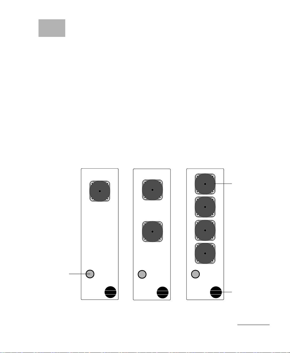
1 Introducing the IQS-1700 High
1 CH Power Meter
IQS-1700
2-CH Power Meter
IQS-1700
C1
C2
C1
C2
C3
4-CH Power Meter
IQS-1700
C4
Optical
detector port
LED push
button
Retaining
screw knob
IQS-1710X IQS-1720X IQS-1740X
Models With Standard Optical Detector Ports
Performance Power Meter
Designed for the IQS-600 Integrated Qualification System, the IQS-1700
High Performance Power Meter is a module available in different models. It
is used with the OHS-1700 Optical Head.
Main Features
The IQS-1700 High Performance Power Meter is offered with the
followingone-, two-, or four-channel models.
The OHS-1700 Optical Head is offered in Ultra-High Power option (up to
37 dBm).
High Performance Power Meter 1
Page 10
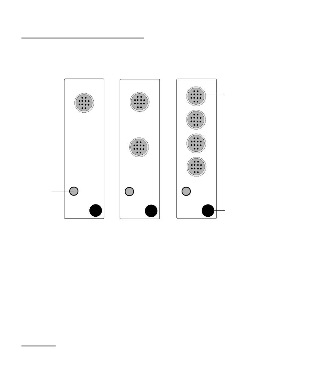
Introducing the IQS-1700 High Performance Power Meter
1 CH Power Meter
IQS-1700
2-CH Power Meter
IQS-1700
C1
C2
C1
C2
C3
E
X
F
O
N
T
T
-
F
C
4-CH Power Meter
IQS-1700
C4
Optical head
connector
LED push
button
Retaining
screw knob
IQS-1710 IQS-1720 IQS-1740
Models With Optical Head Connectors
Main Features
It features a high sampling rate and fast stabilization, and comes in one-,
two- or four-channel options (each detector is independent).
The OHS-1700 Optical Head allows you to handle power signals in a safe
and efficient way. You can connect up to four optical heads to a module,
depending on the model you have acquired. The optical head functions
with connectorized and non-connectorized fiber.
2 IQS-1700
Page 11

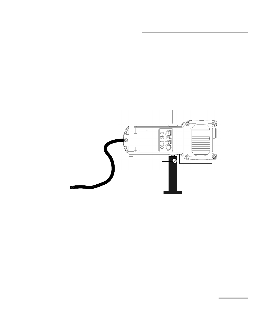
Introducing the IQS-1700 High Performance Power Meter
Connector port to module
Connector port
Tri pod s crew
hole (Metric
system on the
left and
Imperial system
on the right)
Integrating cavity
and heat
dissipator
Main Features
The graphical display mode shows all channels on a real-time graph,
which you can analyze afterwards.
The IQS-1700 High Performance Power Meter supports local control (via
the IQS Manager software) and remote control (through GPIB, RS-232, or
Ethernet TCP/IP using SCPI commands or the provided LabVIEW drivers).
For more information, refer to the IQS platform user guide.
High Performance Power Meter 3
Page 12

Introducing the IQS-1700 High Performance Power Meter
Typi c a l A pp licat i o ns
Typical Applications
Your power meter is suitable for numerous applications, including the
following:
Transceiver testing
Amplifier characterization
PDL measurements
Network monitoring
Passive component characterization
4 IQS-1700
Page 13

Introducing the IQS-1700 High Performance Power Meter
Conventions
Before using the product described in this guide, you should understand
the following conventions:
WARNING
Indicates a potentially hazardous situation which, if not avoided,
could result in death or serious injury. Do not proceed unless you
understand and meet the required conditions.
CAUTION
Indicates a potentially hazardous situation which, if not avoided,
may result in minor or moderate injury. Do not proceed unless you
understand and meet the required conditions.
CAUTION
Indicates a potentially hazardous situation which, if not avoided,
may result in component damage. Do not proceed unless you
understand and meet the required conditions.
Conventions
IMPORTANT
Refers to information about this product you should not overlook.
High Performance Power Meter 5
Page 14

Page 15

2 Safety Information
Your power meter does not contain laser components in itself. However,
you will be using it with light sources.
WARNING
Do not install or terminate fibers while a light source is active.
Never look directly into a live fiber and ensure that your eyes are
protected at all times.
WARNING
The use of controls, adjustments and procedures, namely for
operation and maintenance, other than those specified herein may
result in hazardous radiation exposure or impair the protection
provided by this unit.
IMPORTANT
When you see the following symbol on your unit , make sure
that you refer to the instructions provided in your user
documentation. Ensure that you understand and meet the required
conditions before using your product.
IMPORTANT
Other safety instructions relevant for your product are located
throughout this documentation, depending on the action to
perform. Make sure to read them carefully when they apply to your
situation.
Note: Refer to the platform’s user guide for additional test equipment safety
information and ratings.
High Performance Power Meter 7
Page 16

Page 17

3 Getting Started with Your
High Performance Power
Meter
This chapter contains information on how to insert and remove test
modules. You will also find how to connect your optical head to your
power meter and how to start and exit the application.
Inserting and Removing Test Modules
CAUTION
Never insert or remove a module while the controller unit and its
expansion units are turned on. This will result in immediate and
irreparable damage to both the module and unit.
CAUTION
To avoid damaging your unit, use it only with modules approved by
EXFO.
High Performance Power Meter 9
Page 18
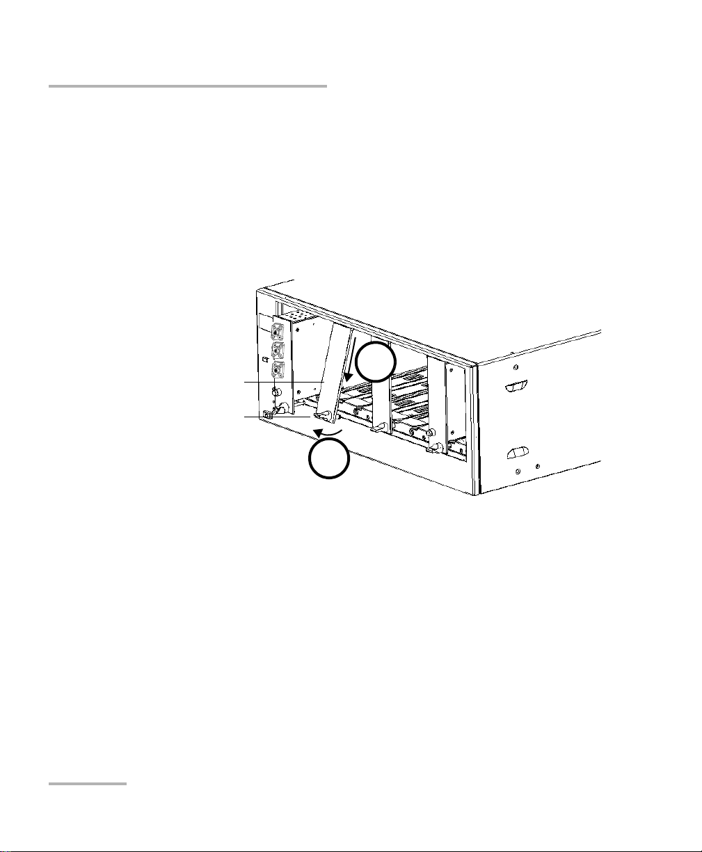
Getting Started with Your High Performance Power Meter
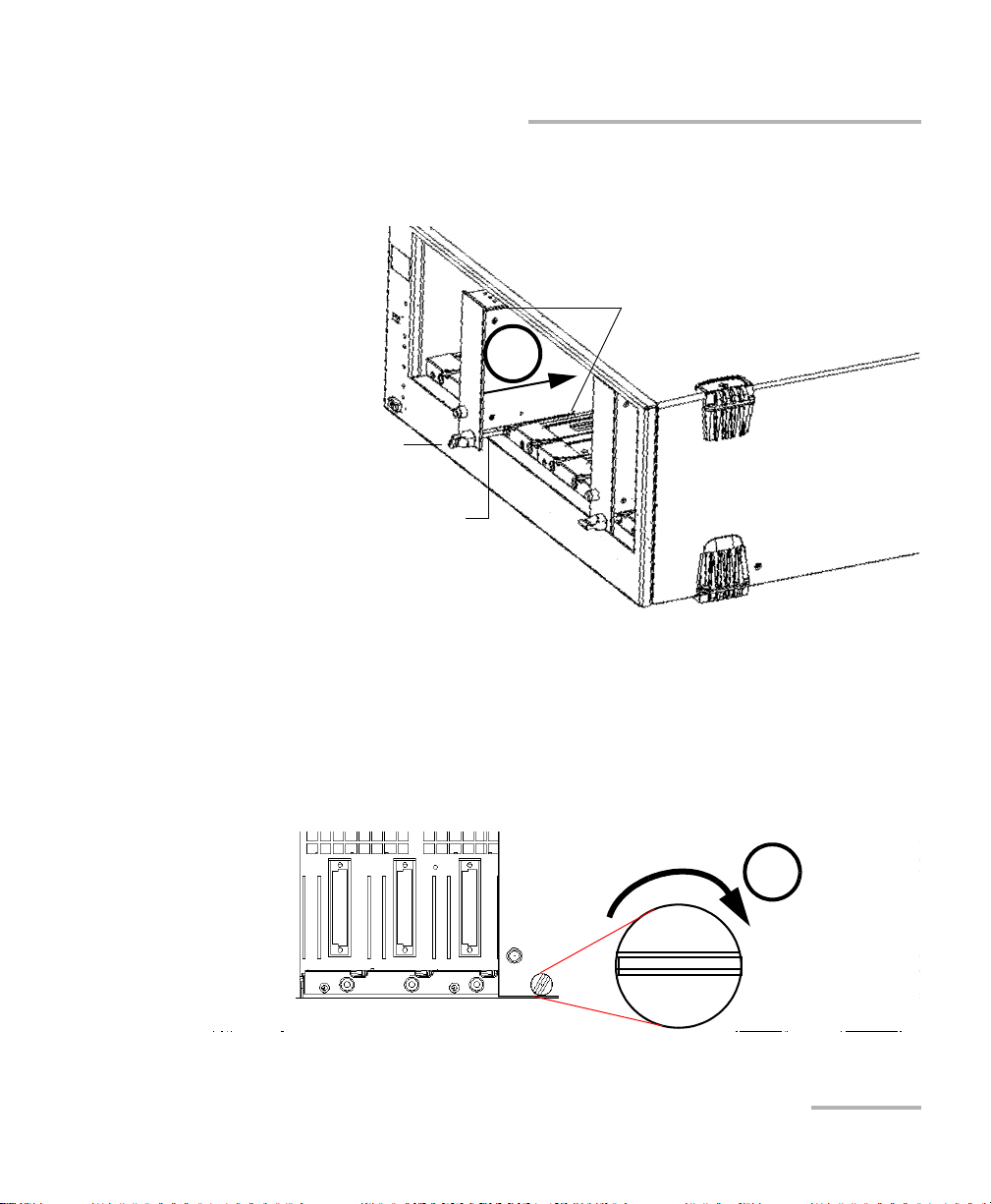
Retaining screw
knob
Protective cover
2b
2a
Inserting and Removing Test Modules
To insert a module into the controller or expansion unit:
1. Exit IQS Manager and turn off all your units.
2. Remove the protective cover from the desired unused module slot.
2a. Pull the retaining screw knob firmly towards you and release the
bottom of the cover.
2b. Gently pull the top of the protective cover downwards, to remove
it from the unit grooves.
3. Position the module so that its front panel is facing you and the top and
bottom protruding edges are to your right.
10 IQS-1700
Page 19
Getting Started with Your High Performance Power Meter
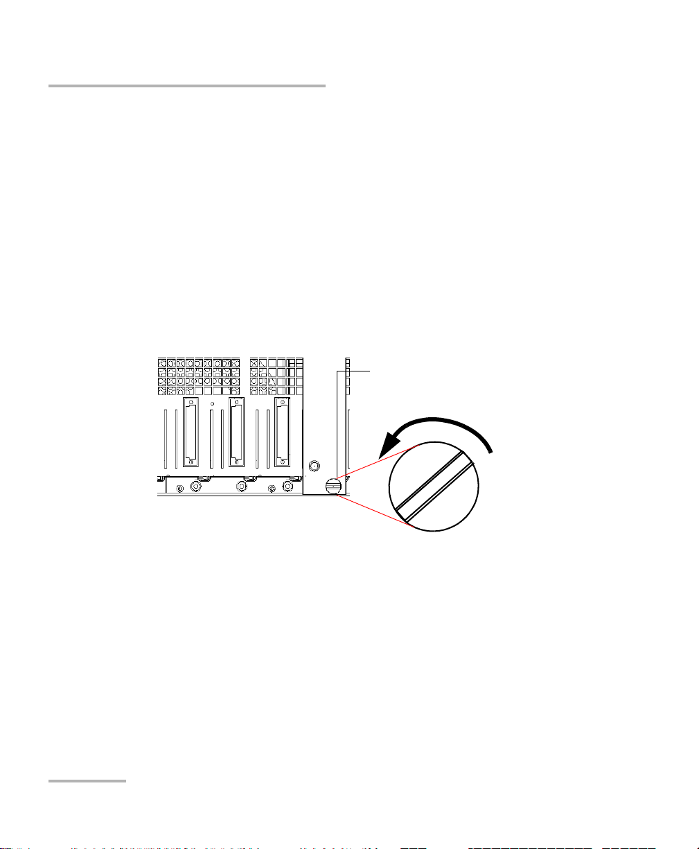
Retaining screw
Retaining screw knob
Protruding edges
(right side of module)
5
6
Inserting and Removing Test Modules
4. Insert the protruding edges of the module into the grooves of the unit’s
module slot.
5. Push the module all the way to the back of the slot, until the retaining
screw makes contact with the unit casing.
6. While applying slight pressure to the module, turn the retaining screw
knob (located at the bottom of the panel) clockwise until the knob is
horizontal.
This will secure the module into its “seated” position.
High Performance Power Meter 11
Page 20
Getting Started with Your High Performance Power Meter
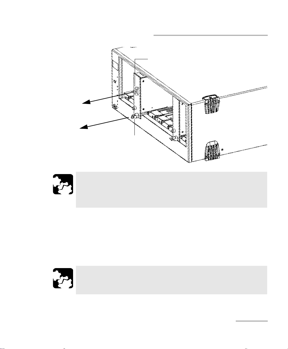
Retaining screw knob
Inserting and Removing Test Modules
The module is correctly inserted when its front panel is flush with the front
panel of the controller or expansion unit.
When you turn on the controller unit, the startup sequence will
automatically detect your module.
Note: You can insert IQ modules into your controller or expansion unit; the
IQS Manager software will recognize them. However, the IQS-1700 locking
mechanism (retaining screw) will not work for IQ modules.
To remove a module from your controller or expansion unit:
1. While pulling gently on the knob, turn it counterclockwise until it stops.
The module will slowly be released from the slot.
2. Place your fingers underneath the module or hold it by the retaining
screw knob (NOT by the connector) and pull it out.
12 IQS-1700
Page 21
Getting Started with Your High Performance Power Meter
YES
NO
Retaining screw
knob
Connector
Inserting and Removing Test Modules
CAUTION
Pulling out a module by a connector could seriously damage both
the module and connector. Always pull out a module by the
retaining screw knob.
3. Cover empty slots with the supplied protective covers.
3a. Slide the top of the protective cover into the upper grooves of the
unit.
3b. Snap the cover into place by pushing the retaining screw knob.
CAUTION
High Performance Power Meter 13
Failure to reinstall protective covers over empty slots will result in
ventilation problems.
Page 22
Getting Started with Your High Performance Power Meter
Head properly connected
Head not connected
Connecting the Optical Head to the Power Meter
Connecting the Optical Head to the
Power Meter
To connect the optical head to the optical head interface, use the provided
cable. Ensure that the connector key is aligned with the port’s
corresponding notch; once the key and pins are properly aligned, the
connection should be made easily.
CAUTION
Do not force the connector into the port if the pins do not seem to
be correctly aligned with the corresponding holes. Forcing the
connector could permanently damage the pins.
Once you have connected the optical head to the interface and started the
application (as explained in Starting the High Performance Power Meter
Application on page 15), you should see the channel or channels (on a
multiple-channel power meter) in the data display.
If the optical head is not connected to its channel, you will notice that the
display is different and you cannot perform measurements on this channel
until you have connected the head properly.
14 IQS-1700
Page 23
Getting Started with Your High Performance Power Meter
Tri pod
Tri p o d scre w
Metric-based
screw hole
Imperial-based
screw hole
Securing the Optical Head onto Your Work Surface
Securing the Optical Head onto Your Work
Surface
Your OHS-1700 Optical Head can be used with a tripod. A metric-based
screw hole is located on the left side of the head and bears the inscription
“M6 X 1” and an imperial-based screw hole is located on the right side and
bears the inscription “1/4-20”.
Once you have installed the head onto the tripod, tighten the tripod screw
to prevent it from turning; which would compromise your test results.
Starting the High Performance Power Meter Application
Your IQS-1700 High Performance Power Meter module can be configured
and controlled from its dedicated IQS Manager application.
Note: For details about IQS Manager, refer to the IQS platform user guide.
High Performance Power Meter 15
Page 24
Getting Started with Your High Performance Power Meter
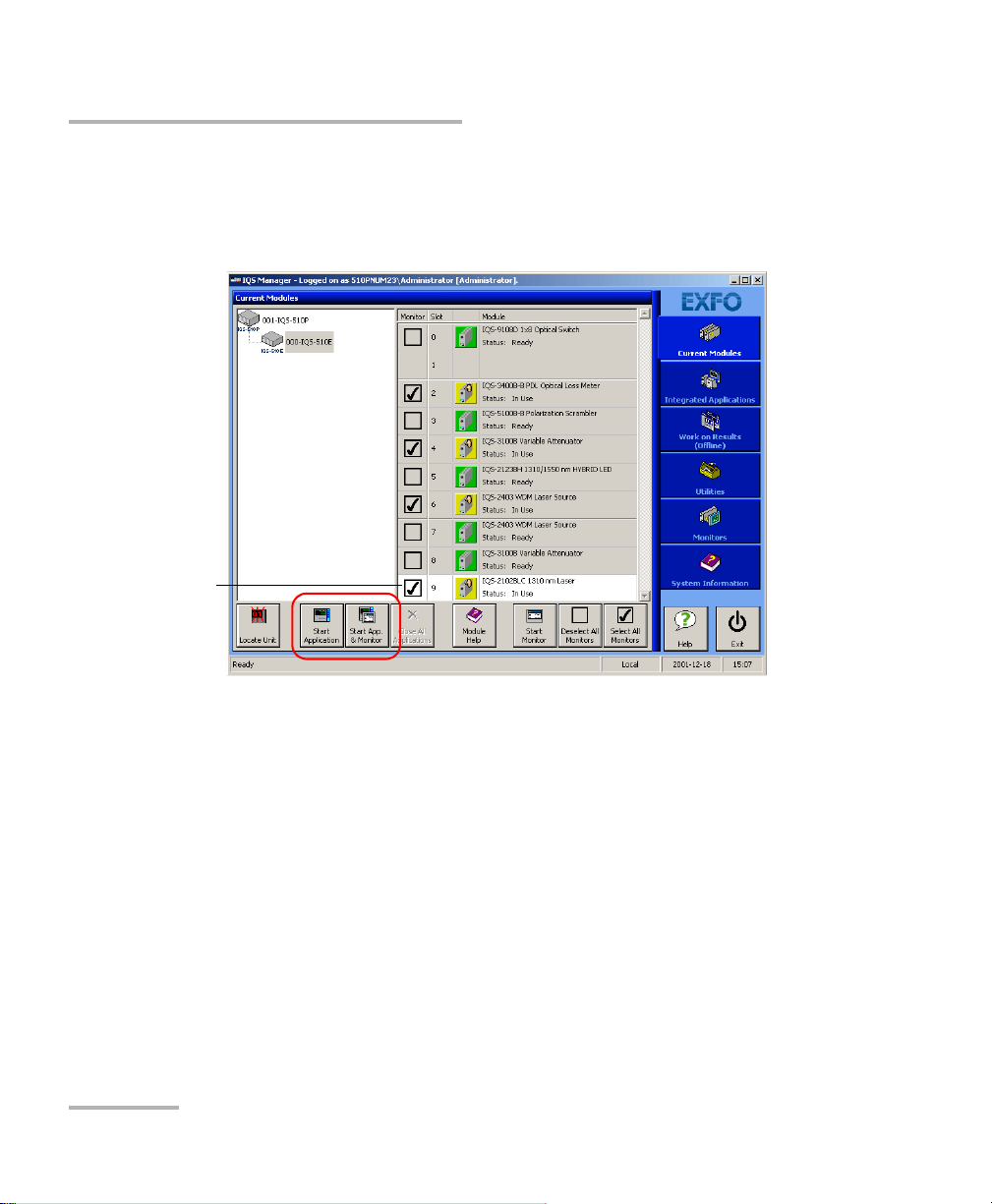
Highlighted module
(white background)
Starting the High Performance Power Meter Application
To start the application:
1. From the Current Modules function tab select the module to use.
It will turn white to indicate that it is highlighted.
Note: Pressing the LED push button will not activate or turn on the module.
Note: To start the corresponding monitor window at the same time, click Start
16 IQS-1700
2. Click Start Application.
OR
Press the green LED push button on the front of the corresponding
module.
You can also double-click its row.
App. & Monitor. The window opens on the Monitors function tab.
Page 25
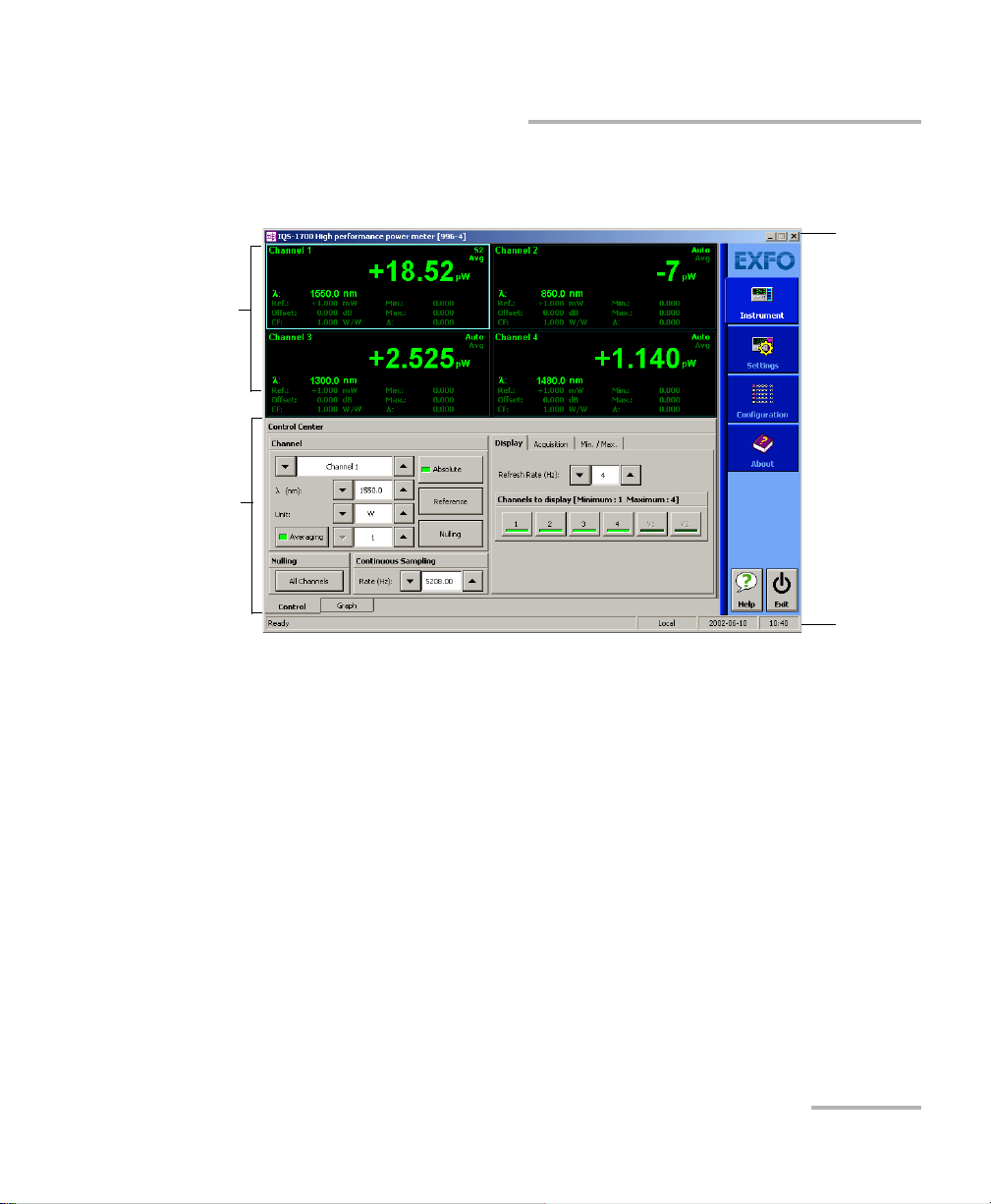
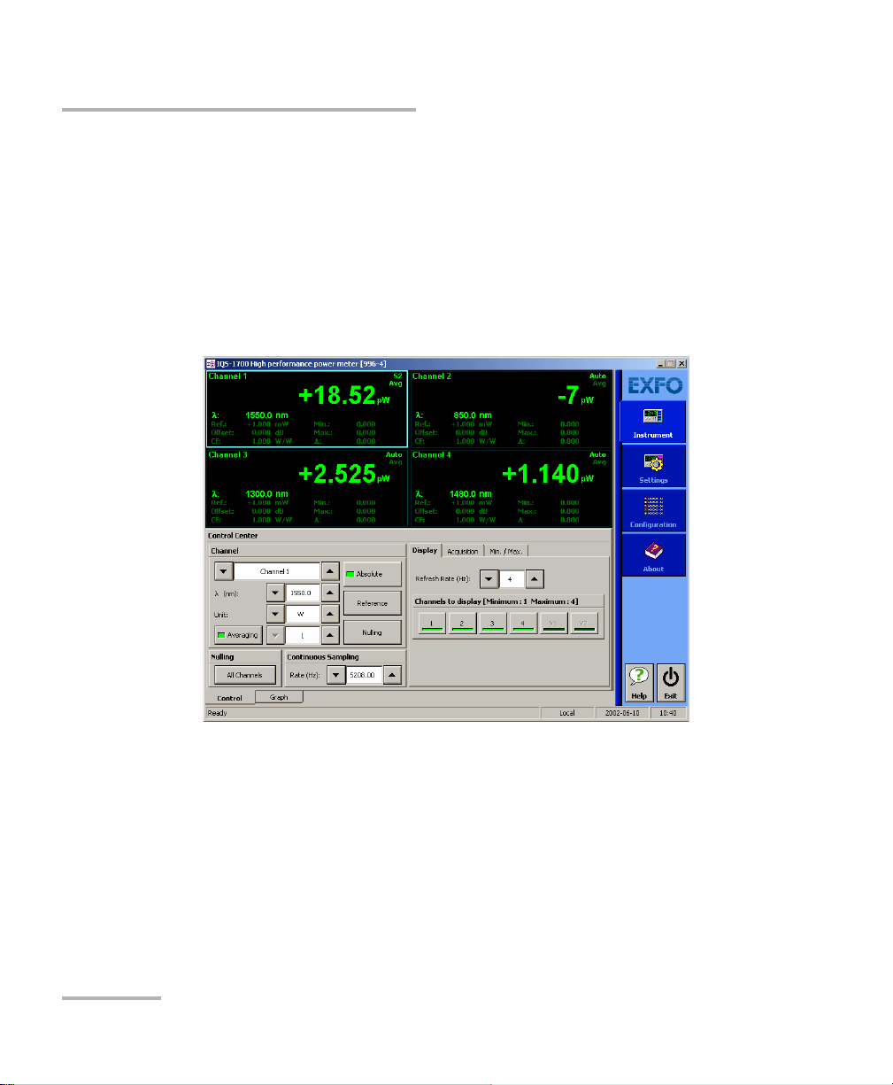
Getting Started with Your High Performance Power Meter
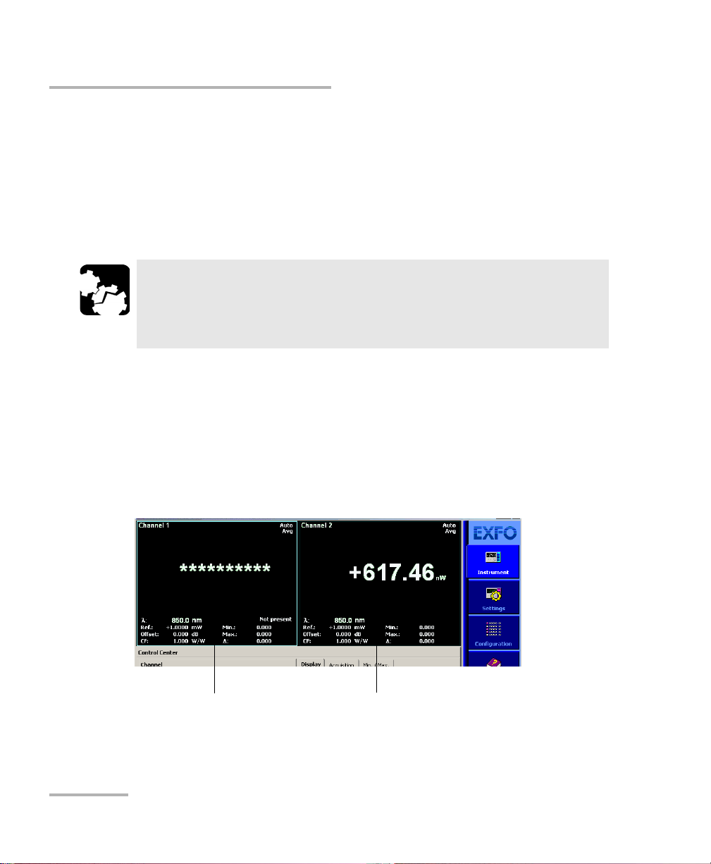
Parameter
definition
controls
Data
display
Title bar
Status bar
Starting the High Performance Power Meter Application
The main window (shown below) contains all the commands required to
control the High Performance Power Meter:
Note: When using a multichannel power meter with different optical heads, the
settings (such as the wavelength list) used by the application are those
detected on the highest channel number. For example, if you use a
Low-PDL head on channel 2 and a high-power head on channel 3, the
high-power head settings will take precedence. If you move the head from
channel 3 to channel 1, the Low-PDL head will be used for settings instead.
High Performance Power Meter 17
Page 26

Getting Started with Your High Performance Power Meter
Slot number in which module is inserted
(0 identifies first slot)
Controller unit or expansion unit (1 to 999) housing
the module
[999–1]
Current date and timeModule/unit status
Local: Module controlled locally only.
Remote: Module controlled remotely, but
local commands can also be used.
Lockout: Module controlled remotely only.
Control mode
Starting the High Performance Power Meter Application
Title Bar
The title bar is located at the top of the main window. It displays the
module name and its position in the controller or expansion unit. The
module position is identified as follows:
Status Bar
The status bar, located at the bottom of the main window, identifies the
operational status of the IQS-1700 High Performance Power Meter.
For more information about automating or remotely controlling the
IQS-1700 High Performance Power Meter, refer to your platform user guide.
18 IQS-1700
Page 27
Getting Started with Your High Performance Power Meter
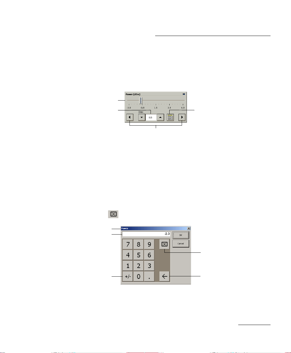
Numeric box
button
Fine-tuning
box
Slider
Navigation buttons
Parameter identification
Toggle button
Backspace button
(to correct a value)
Clear button
Entry display
Entering Values Using Sliders and Numeric Boxes
Entering Values Using Sliders and Numeric
Boxes
Many parameters in IQS Manager and module applications can be set
using the following tools.
Slider: Drag it to the desired value on the scale below.
Navigation buttons: Click either buttons to move the slider. The slider
moves by steps corresponding to the number in the fine-tuning box,
which you can change by using the up and down arrow buttons next to
the box. You cannot change the list of fine-tuning values from here.
Numeric box: Click it to display the on-screen numeric pad, which you
can use to enter a power value.
High Performance Power Meter 19
To enter a value using the numeric box:
1. Use the button to clear the entry display.
2. Enter the value.
3. Click OK to confirm the value.
Page 28

Getting Started with Your High Performance Power Meter
Exiting the Application
Exiting the Application
Closing any application that is not currently being used helps freeing
system memory.
To close the application from the main window:
Click in the top right corner of the main window.
OR
Click the Exit button located at the bottom of the function bar.
To close all currently running applications:
From IQS Manager, click Close All Applications.
20 IQS-1700
Page 29

4 Setting Up Your High
Performance Power Meter
You can set the following parameters on your IQS-1700:
Channel display
Wavelength selection and management
Measurement unit selection
Display resolution
Refresh rate
Measurement range
Saving and recalling configuration
High Performance Power Meter 21
Page 30
Setting Up Your High Performance Power Meter
Setting Channel Display
Setting Channel Display
The channel display allows you to select which channels you want to view
when using a multichannel power meter. You can display up tofour optical
channels using a four-channel power meter.
To set the channel display :
1. From the Instrument function tab, click the Display tab to view the
available channels.
2. Select the desired channel.
The data display immediately reflects your selection and the selected
channel indicator will turn light green.
22 IQS-1700
Page 31

Setting Up Your High Performance Power Meter
Selecting a Channel (Multi-Channel Models)
Selecting a Channel (Multi-Channel Models)
The optical channels on multi-channel models are independent.
To select an optical channel:
From the Instrument function tab, go to Channel and use the arrow
buttons next to the channel number to change it.
OR
Click the appropriate data display zone.
A colored frame will indicate your selection.
High Performance Power Meter 23
Page 32

Setting Up Your High Performance Power Meter
Naming Channels
Naming Channels
A user-selected name can be given to each power meter channel. The
channel name appears in the main window. Naming individual channels is
particularly useful when you need to display more than one power channel
at the same time, especially in Monitor Window mode with several optical
power meters displayed simultaneously. The name should be as
self-explanatory as possible (for example, Power-Fiber 3).
To enter a channel name:
1. Click the Settings function tab.
2. From the Channels tab, select the channel to name by clicking the
corresponding button.
3. Type in a self-explanatory name in the Name box.
4. Click Apply to confirm your new setting.
24 IQS-1700
Page 33

Setting Up Your High Performance Power Meter
Wavelength list
Selecting the Wavelength
Selecting the Wavelength
When taking accurate measurements, your power meter must be set to
the correct wavelength to compensate for the photodetector responsivity
at the incident wavelength. Ideally, the power meter’s wavelength should
be set as close as possible to that of the optical source being used.
The wavelength must be selected from the wavelength list. To set the
wavelength list, see Managing Wavelength Lists on page 26.
To select the wavelength (either from the Instrument or Settings
function tab):
1. Select the channel for which you want to set the wavelength (if you
have a multiple-channel power meter).
2. Select the wavelength using the arrow buttons next to the list.
3. If you are in the Channels tab of the Settings function tab, click Apply
to confirm your new setting.
Note: You can also use the All Channels button to modify all channels identically.
Values previously set will turn red to indicate that the new setting differs.
High Performance Power Meter 25
Page 34

Setting Up Your High Performance Power Meter
Managing Wavelength Lists
Managing Wavelength Lists
The wavelengths you want to use with your IQS-1700 and OHS-1700 must
be entered in the Wavelength list. Please refer to the Certificate of
Compliance supplied with your power meter for information on the
wavelength range.
To add a wavelength to the list:
1. From the Settings function tab, select the Lists tab.
2. In the Wavelength list, enter the wavelength value to be added.
You can enter a value with a 0.01 nm resolution.
3. Click to confirm the new wavelength.
Note: A warning message is displayed if the new wavelength is not within the
power meter’s wavelength range.
26 IQS-1700
Page 35

Setting Up Your High Performance Power Meter
Selecting the Measurement Unit
To delete a wavelength from the list:
1. From the Settings function tab, click the List tab.
2. From, the Wavelengt h list, select the wavelength to be deleted.
3. Click to confirm the operation.
Note: It is not possible to delete a wavelength that is currently being used.
Selecting the Measurement Unit
Power measurements can be displayed in dB, dBm, W, or W/W (the latter
indicating the ratio between the power received and the reference for the
current wavelength and channel). When W or W/W is selected, the
software automatically selects W units (pW, nW, W, mW), depending on
the measured power and sensitivity of the detector.
When a relative unit is selected (dB or W/W), the most recent reference
value used will become the current reference value.
To select the measurement unit (either from the Instrument or
Settings function tab):
1. Select the channel for which you want to set the measurement unit (if
you have a multiple-channel power meter).
2. Use the arrow buttons next to the Unit list to change the value.
3. click Apply to confirm your new setting.
Note: You can also use the All Channels button to modify all channels identically.
If other values were set before, but are different from those you are setting,
any value you change will turn red to indicate that it is different.
High Performance Power Meter 27
Page 36

Setting Up Your High Performance Power Meter
Setting the Display Resolution
Setting the Display Resolution
Depending on the required resolution and operating power level, 0, 1, 2, 3,
or 4 digits can be displayed after the decimal point. When the auto setting
is selected, the display resolution is determined by the power level being
measured.
Note: The Auto marker in the data display does not refer to the automatic display
resolution but to the measurement range (see Setting the Measurement
Range on page 31).
To select the display resolution of a power measurement
expressed in dB or dBm:
1. Click the Settings function tab, then click the Channels tab.
If necessary, select the channel for which you want to set the display
resolution.
2. Use the arrow buttons to select the value in the Display Res. list.
28 IQS-1700
Page 37

Setting Up Your High Performance Power Meter
Setting the Display Resolution
If you have previously selected watts as units, the Display Res. list will
be grayed out (as illustrated above).
3. Click Apply to confirm your new setting.
Note: You can also use the All Channels button to modify all channels at once. If
other values were set previously, but are different from those you are
currently setting, any value you change will turn red to indicate that it is
different.
Note: When W or W/W is selected, the display resolution changes to Auto (the
appropriate W unit will be used according to the power of the signal
detected). It is then impossible to access the display resolution list.
High Performance Power Meter 29
Page 38

Setting Up Your High Performance Power Meter
Setting the Refresh Rate
Setting the Refresh Rate
This function allows you to define the refresh rate of the power readings on
the display. The refresh rate is the number of times per second that a new
power measurement will be displayed on the screen. The refresh rate
applies to all channels when using a multichannel power meter.
To set the refresh rate:
1. From the Instrument tab, select the Display tab.
2. Use the arrow buttons to select the refresh rate you want to use.
Note: The refresh rate can be faster or slower than the sampling rate; however,
only a refresh rate slower than the sampling rate will have an effect.
30 IQS-1700
Page 39

Setting Up Your High Performance Power Meter
Setting the Measurement Range
Setting the Measurement Range
The measurement range and gain scale applied to the power detector can
be manually selected to prevent the automatic scale adjustment
performed by the instrument. A manual adjustment of the dynamic gain
scale will lock the measurement range to a specific level.
It is necessary to use a manual range to achieve high-rate acquisitions (see
Performing Acquisitions on page 57).
Each channel is adjusted independently in the case of a multichannel
power meter.
High Performance Power Meter 31
Page 40

Setting Up Your High Performance Power Meter
Setting the Measurement Range
To set the measurement range:
1. Click the Settings function tab, then select the Channels tab.
2. If necessary, select the channel for which you want to set the range.
3. Use the arrow buttons next to the Range list to select the range you
want to use.
Note: Select Manual range for an acquisition when the input signal has unstable
or modulated variations. This prevents !!!!!!! from appearing on the
display when changing gain scales often.
32 IQS-1700
Page 41

Setting Up Your High Performance Power Meter
Setting the Measurement Range
4. Use the arrow buttons next to the Scale list and highlight the scale you
wish to use.
5. Click Apply to confirm your new setting.
Note: You can also use the All Channels button to modify all channels identically.
If other values were set previously, but are different from those you are
currently setting, any value you change will turn red to indicate that it is
different.
High Performance Power Meter 33
Page 42

Setting Up Your High Performance Power Meter
To save parameters being used
just before shutting down,
overwriting the previous file.
To always use the last saved
parameters when starting.
Saving and Recalling Configurations
Saving and Recalling Configurations
Once you have set the IQS-1700 High Performance Power Meter
parameters, you can save your custom configuration and recall it at any
time. You can also recall the factory-defined settings.
Saved configurations include all parameters set in the Control Center
(Instrument function tab) and in the Settings function tab (if present).
To save a configuration:
1. Select the Configuration function tab.
2. In the Current Module Configuration panel, enter the name you wish
to use for your configuration file.
It will be saved in
D:\IQS Manager\Configuration Files\(your_module)\.
3. Click Save.
34 IQS-1700
Page 43

Setting Up Your High Performance Power Meter
Saving and Recalling Configurations
To recall a configuration:
1. Select the Configuration function tab.
2. Click Open.
3. Select the configuration file you wish to recall and confirm your action.
You are returned to the application and the new parameters are set.
To revert to factory settings:
1. Select the Configuration function tab.
2. Click the Reset Module to Factory Settings button.
IMPORTANT
Reverting to the factory settings will interrupt any module
operation in progress.
IMPORTANT
The operation may take a few seconds to complete.
Note: Reverting to factory settings will not change the name given to the
channels. It will not change the user reference or correction factor lists
either.
High Performance Power Meter 35
Page 44

Page 45

5 Preparing Your High
Performance Power Meter for
a Test
The OHS-1700 Optical Head can be used with connectorized or
nonconnectorized fiber (using the FOA-3000 and BFA-3000 Bare Fiber
Adaptor). Each head has its own port, onto which you can connect a fiber.
Ensure you use the appropriate adaptors such as the FOA-3000 or the
BFA-3000 to combine your power meter to the optical head. You also have
to clean optical fibers properly before connecting them to your unit.
Cleaning and Connecting Optical Fibers
IMPORTANT
To ensure maximum power and to avoid erroneous readings:
Always inspect fiber ends and make sure that they are clean as
explained below before inserting them into the port. EXFO is
not responsible for damage or errors caused by bad fiber
cleaning or handling.
Ensure that your patchcord has appropriate connectors. Joining
mismatched connectors will damage the ferrules.
To connect the fiber-optic cable to the port:
1. Inspect the fiber using a fiber inspection microscope. If the fiber is
clean, proceed to connecting it to the port. If the fiber is dirty, clean it as
explained below.
2. Clean the fiber ends as follows:
2a. Gently wipe the fiber end with a lint-free swab dipped in isopropyl
alcohol.
2b. Use compressed air to dry completely.
2c. Visually inspect the fiber end to ensure its cleanliness.
High Performance Power Meter 37
Page 46

Preparing Your High Performance Power Meter for a Test
Cleaning and Connecting Optical Fibers
3. Carefully align the connector and port to prevent the fiber end from
touching the outside of the port or rubbing against other surfaces.
If your connector features a key, ensure that it is fully fitted into the
port’s corresponding notch.
4. Push the connector in so that the fiber-optic cable is firmly in place,
thus ensuring adequate contact.
If your connector features a screwsleeve, tighten the connector
enough to firmly maintain the fiber in place. Do not overtighten, as this
will damage the fiber and the port.
Note: If your fiber-optic cable is not properly aligned and/or connected, you will
notice heavy loss and reflection.
EXFO uses good quality connectors in compliance with EIA-455-21A
standards.
To keep connectors clean and in good condition, EXFO strongly
recommends inspecting them with a fiber inspection probe before
connecting them. Failure to do so will result in permanent damage to the
connectors and degradation in measurements.
38 IQS-1700
Page 47

Preparing Your High Performance Power Meter for a Test
Nulling Offsets
Nulling Offsets
Temperature and humidity variations affect the performance of electronic
circuits and optical detectors, which can offset measurement results. To
compensate for this offset, the unit is equipped with an offset nulling
function.
Your unit is designed not to require offset nulling under normal operation,
but you should perform it whenever environmental conditions change
significantly or when measuring very low power values.
Note: The manual nulling offset is valid for the current test session only; it no
longer applies when you turn off your power meter.
IMPORTANT
Light must not reach the detector when performing an offset
nulling operation. Always use a protective screw cap. Do not use a
soft rubber cover
High Performance Power Meter 39
Page 48

Preparing Your High Performance Power Meter for a Test
Nulling Offsets
To perform an offset nulling on one channel:
1. Install the protective cap over the detector port.
2. If necessary, select the desired channel (on a multichannel high-speed
power meter).
To set the channel, see Selecting a Channel (Multi-Channel Models) on
page 23.
Offset nulling values are applied to the channel until a new nulling is
performed.
3. Under Channel, click the Nulling button. A message prompts you to
ensure that the detector cap is properly installed.
4. Select OK to perform the offset nulling, or Cancel to exit.
A red message appears beneath the power value of the channel for
which you are performing a nulling.
If you are using a multichannel power meter, you will notice that the
other channels will stop reading power while nulling is in progress.
40 IQS-1700
Page 49

Preparing Your High Performance Power Meter for a Test
Nulling Offsets
To perform an offset nulling on all channels (two- and
four-channel power meters):
1. Install the protective caps over all of the detector ports.
2. Under Nulling, click the All Channels button.
Offset nulling values are applied to the channel until a new nulling is
performed. A message prompts you to ensure that the detector caps
are properly installed.
High Performance Power Meter 41
Page 50

Preparing Your High Performance Power Meter for a Test
Nulling Offsets
3. Click OK to perform the offset nulling, or Cancel to exit.
A red message appears beneath the power value of the channel for
which you are performing a nulling.
42 IQS-1700
Page 51

6 Measuring Power
Power measurements can be displayed in two ways:
absolute
relative
It is also possible to use a correction factor at specific wavelengths and to
add an offset value to your power measurement.
Displaying Absolute Power
When in absolute power, measured values are displayed in either dBm or
W units (pW, nW, W, mW...) and the displayed value represents the
absolute optical power reaching the detector within specified uncertainty.
High Performance Power Meter 43
Page 52

Measuring Power
Displaying Absolute Power
To display absolute power:
1. Select the Instrument function tab or the Channels tab of the Settings
function tab (you can use either).
2. Select the channel for which you want to set the offset if you are using
a multichannel power meter.
Note: Step 3 is not mandatory, but will help you achieve more precise results.
3. Select the appropriate wavelength by using the arrow buttons next to
the corresponding list.
4. Select the appropriate unit by using the arrow buttons next to the
corresponding list (W or dBm).
5. If you are in the Settings function tab, click Apply to confirm your new
setting.
6. Return to the Instrument function tab and click Absolute to activate
the mode.
An absolute power measurement in negative W units indicates that the
nulling of the offset was improperly done. If this happens, repeat the offset
nulling operation (see Nulling Offsets on page 39).
44 IQS-1700
Page 53

Measuring Power
Measuring Relative Power
Measuring Relative Power
Power measurements can be displayed as a deviation from an absolute
reference value. The relative power is particularly useful when performing
loss measurements.
Relative power is displayed in dB when the reference value is measured in
dBm. In this case, the value will be either positive or negative, as the actual
measured power is higher or lower than the reference power.
If the reference value is in W, the relative power will be displayed in W/W.
In this case, the relative power is the deviation ratio from the reference and
will always be a positive value (unless operation was improperly done).
To display significant relative power values, it is important to have an
appropriate reference value, which you activate by clicking the Reference
button in the Instrument function tab. You can either apply the current
module power as a reference or edit a value to be used as the reference.
High Performance Power Meter 45
Page 54

Measuring Power
Selecting the Reference Value
Selecting the Reference Value
The reference value influences your measurements once selected and
activated. Whether you select the current module’s power or a set value
from the list, this becomes the basis for your future acquisitions.
To select the reference value:
1. From the Settings function tab, select the Channels tab.
2. Use the arrow buttons next to Reference to select either the current
module’s power or a value from the list, which you can then edit as
explained in the following section.
3. Click Apply to confirm your new setting.
4. From the Instrument function tab, click the Reference button to use
your new reference value.
46 IQS-1700
Page 55

Measuring Power
Editing the Reference List
Editing the Reference List
The Reference list can be changed to adapt to your testing requirements.
To add a reference to the list:
1. From the Settings function tab, select the Lists tab.
2. Under Reference List, enter the name of the new reference value in
the Name box.
3. In the Ref (dBm) box, enter a reference between 100.000 dBm and
100.000 dBm.
4. Click to enter the value.
Note: Although the wavelength list applies to all channels, the selected reference
applies to the wavelength and channel at which it was set.
High Performance Power Meter 47
Page 56

Measuring Power
Measuring Corrected Power
To delete a user reference from the list:
1. From the Settings function tab, select the Lists tab.
2. Select the value to remove by clicking it once.
3. Click to remove the value.
Measuring Corrected Power
Applying a correction factor to the measured power is useful when
compensating for known inaccuracies (power gains or losses) at specific
wavelengths.
A correction factor (CF) can be applied to any measurement that is
displayed in either dB, dBm, W, or W/W.
When a dB correction factor different from 0.000 is defined, the displayed
power is equal to the actual power plus the value of the correction factor.
When a W/W correction factor different from 1.000 is defined, the
displayed power is equal to the actual power times the value of the
correction factor.
Note: With an active correction factor, the CF marker appears in the data display
for the matching channel.
Note: Special care must be taken when setting a CF as it emulates a new
calibration (the module calibration is not affected and will be restored by
setting back the CF to a null value).
When expressed in dB, the CF can be a positive or negative value. When
the currently selected measurement unit is W, the correction factor is
expressed in W/W, indicating a multiplication factor for the current
wavelength and channel. The CF expressed in W/W will always be a
positive value.
48 IQS-1700
Page 57

Measuring Power
Measuring Corrected Power
To set a correction factor:
1. From the Settings function tab, select the Channels tab.
2. Select the channel for which you want to set the CF (in the case of a
two- or four-channel power meter).
3. Select the wavelength to which the CF will be applied by using the up
and down arrow buttons next to the list or by clicking it once in the
Correction Factors list.
4. In the Factor (unit) box, enter a CF between 10.000 dB and
10.000 dB, or between 0.100 W/W and 10.000 W/W, then click .
Note: Although the wavelength list applies to all channels, the CF applies to the
wavelength and channel at which it was set.
To remove the offset from a wavelength, select the wavelength,
then click .
High Performance Power Meter 49
Page 58

Measuring Power
Using the Offset Function
Using the Offset Function
The offset function is used when you want to take into account, in the
power displayed, a known gain or loss in the link that is not already
included in the signal reaching the detector. Contrary to the correction
factor, which applies to a specific wavelength, the offset value applies to
any wavelength when it is enabled in a specific channel.
To enter an offset value:
1. From the Settings function tab, select the Channels tab.
2. Select the channel for which you want to set the offset if you are using
a multichannel power meter.
3. From the Offset list, use the arrow buttons to adjust the value.
4. Click Apply to confirm your new setting.
50 IQS-1700
Page 59

Measuring Power
yn
1
M
---- -
xn 1
1
M
---- -
–
yn 1–+=
Averaging Measurements
Averaging Measurements
When the averaging function is enabled on the IQS-1700 High Performance
Power Meter, the most recent measurement samples, for which you can
set the number, are used to compute an unweighted average. This average
is displayed as the measured value. The AVG marker will also be displayed
to the right of the value for the matching channel, indicating that averaging
is enabled.
Averaging can be done on a minimum of 2 and a maximum of 1000 points
(you can enter 1 as a value, but the averaging will be performed only on
that value and will be rather useless). The calculation uses watt as unit, but
the result will be converted into the unit you have selected for your
acquisition (W, W/W, dBm or dB) afterwards.
The formulas used to calculate measurement averaging depend on the
number of the current acquisition.
If n M, then
Where
n is the number of the current acquisition
M is the number of points to average (value you set)
x[n] is the current sample in watts
y[n] is the result of the present average in watts
y[n-1] is the value before the average in watts
High Performance Power Meter 51
Page 60

Measuring Power
Average /Averaging lists
Averaging Measurements
Note: When measurement conditions change, the number of the acquisition is
reset to zero in order to start a new averaging measurement with the new
settings.
To select the number of samples for averaging, whether you are in the
Instrument function tab or the Channels tab of the Settings function tab,
use the arrow buttons to change the value in the Average (in the Settings
function tab) or Averaging (in the Instrument function tab) lists.
If you are setting the average value in the Instrument function tab, you
must first press the Averaging button to activate the list.
To toggle between averaged and unaveraged power
measurement:
1. If necessary, select the desired channel from the Instrument function
tab.
2. Click the Averaging button to activate or deactivate it.
52 IQS-1700
Page 61

7 Recording Power Signal
Variations
The Min./Max. function allows you to record the extremes of a varying
power signal when performing a continuous acquisition. For example,
it could be used to determine the stability of a light source over time or to
measure the polarization-dependent loss (PDL) of a passive component
when combined with a polarization state controller.
The function is started manually and can be stopped manually or
automatically using the timer function. Minimum (Min.) and maximum
(Max.) values can be recorded and displayed in any measurement unit
(dB, dBm, W, or W/W; seeSelecting the Measurement Unit on page 27).
In logarithmic scales (dB and dBm), the difference between the maximum
and minimum values is expressed as Max.Min. In linear scales (W and
W/W), the difference is expressed as a ratio (Min./Max.).
To use the Min./Max. function:
1. Select the Continuous acquisition rate (seeSelecting the Sampling
Type on page 58).
High Performance Power Meter 53
Page 62

Recording Power Signal Variations
Selection
indicators
2. Select the channel for which you want to see the power variation data
on-screen by clicking the corresponding buttons in the Min./Max. tab.
3. If you want to specify the duration of power measurements, click the
Use Timer button, then enter a span using the arrow buttons on each
side of the list. If you are using the numeric box to enter a time value,
you must enter it in seconds (for example, 120 seconds for 2 minutes).
4. Click Start to start power measurements.
These can be stopped at any time by clicking Stop. If the timer is set,
power measurements will stop automatically after the specified
duration.
Note: The remaining duration is indicated under the Start and Stop button.
The Reset button will reinitialize the Min./Max. acquisition results in the
data display.
54 IQS-1700
Page 63

Recording Power Signal Variations
The results of the Min./Max. function are continuously updated in the
matching lists. When a logarithmic scale is used, the Max.Min.
calculation is made to continuously provides the difference between the
two extremes. In a linear scale, the Min./Max. ratio is computed to provide
valuable information.
If the power reaches the saturation level, +++++++ will be
recorded as the Max. value. The Max.-Min. or Min./Max. calculation will
also be +++++++.
If the detected power decreases below the lowest measurable power,
the Min. value will be ––––––– and both Max.-Min. or Min./Max. will
display –––––––.
If a Min./Max. calculation is made with a null Min. value, !!!!!!! will
be displayed.
If a channel is shown in the data display but is not part of the selected
channels for a Min./Max. acquisition, ******* will be displayed to
indicate that no power reading is being performed at that time.
Selecting Autorange for this channel will prevent these symbols from
appearing.
High Performance Power Meter 55
Page 64

Page 65

8 Performing Acquisitions
You can perform your acquisition on one or several channels at the same
time (in the case of multichannel power meters).
To select which channel will be affected by your acquisition:
1. From the Settings function tab, select the Data Acquisition tab.
2. Press on the corresponding button in the Channels To Be Included in
Sample.
You can set a location where the acquisitions will be stored when you do
your tests.
To select a path for storing your acquisitions:
1. From the Settings function tab, select the Data Acquisition tab.
2. Use to select the folder to save your file.
High Performance Power Meter 57
Page 66

Performing Acquisitions
Selecting the Sampling Type
Selecting the Sampling Type
You can perform different types of samplings with your power meter:
Continuous sampling signifies that power measurements are
constantly updated on the measurement display for an unlimited time
period. You can select a rate that will optimize instrument flexibility
and measurement stability as well as determine the quantity of data
generated during data acquisition.
Single sampling signifies that power measurements will be taken
once, at the rate you have selected. This type of acquisition is
particularly useful when using a high acquisition rate, since the higher
the rate, the more data is transmitted. It will be easier for your power
meter module to manage one huge input of points as opposed to
several at the same time (it will stop analyzing if overwhelmed by
data).
User Defined sampling signifies that you can enter the rate and the
time units you wish to use. The value you enter in the 1/ list is the
number of time units the acquisition process will use. For example, if
you enter a value of 10, and select seconds as the unit, an acquisition
will be performed once every ten seconds; if you enter a value of 1 and
select seconds as the unit, an acquisition will occur every second, etc.
58 IQS-1700
Page 67

Performing Acquisitions
Selecting the Sampling Type
To select a sampling type:
1. From the Settings function tab, select the Data Acquisition tab.
2. Select the sampling type by clicking the corresponding button.
If you select Continuous, select the rate to use with the arrow buttons.
This rate is a divider of the maximum rate (5208 Hz). For example,
5208 Hz has a divider of 1, 2604 has a divider of 2 and so forth. To add
or remove dividers from the list of available values, see Editing the
Frequency Divider List on page 61.
High Performance Power Meter 59
Page 68

Performing Acquisitions
Selecting the Sampling Type
The acquisition rate applies to all channels when using a multichannel
power meter.
You can also change the continuous sampling rate in the Instrument
function tab in the same manner.
If you select Single, select the rate to use with the arrow buttons.
This rate is a divider of the maximum rate (5208 Hz). For example,
5208 Hz has a divider of 1, 2604 has a divider of 2 and so forth. To add
or remove dividers from the list of available values, see Editing the
Frequency Divider List on page 61. The acquisition rate applies to all
channels when using a multichannel power meter.
If you select User Defined, select the rate by entering a value in the 1/
list, then select a time unit using the arrow buttons. Remember to click
to confirm your settings.
Note: Use a lower sampling rate with averaging set to active (see Averaging
Measurements on page 51) for greater repeatability when measuring very
low power.
60 IQS-1700
Page 69

Performing Acquisitions
Editing the Frequency Divider List
Editing the Frequency Divider List
To select the frequency at which your continuous or single acquisition will
be performed, use a value which is a divider of the full frequency value,
5208 Hz. The values available to you are listed located in the List tab of the
Settings function tab.
To enter a new divider, simply type it in the Divider box. The Frequency
(Hz) box will be automatically updated with the proper value. To confirm
your new value, click .
To remove a divider from the list, select it by clicking it once, then click .
High Performance Power Meter 61
Page 70

Performing Acquisitions
Selecting the Acquisition Mode
Selecting the Acquisition Mode
You can use three data acquisition modes, regardless of the type of
acquisition you are performing.
Timer: the acquisition will last for the length of time you have
previously set.
Trigger : the power meter will wait for an incoming trigger signal
before starting its next acquisition.
Delay: the power meter will wait for a set length of time between
acquisitions.
Note: You can use one, several or all modes at the same time. If you use both the
trigger and delay modes simultaneously, the power meter will first wait for
the set delay time to elapse, then wait again for the incoming trigger signal.
If you add the timer mode, the acquisitions will be performed during a set
length of time, using both the trigger and delay modes.
In each case, measurements are taken at the selected sampling rate and
saved to a user-specified data file. The size of the data files created during
acquisition is proportional to the sampling rate and duration of the
acquisition. Higher sampling rates and longer durations generate larger
quantities of data.
62 IQS-1700
Page 71

Performing Acquisitions
Selecting the Acquisition Mode
To select the acquisition mode:
1. From the Settings function tab, select the Data Acquisition tab.
2. From Mode, select the desired mode or combination of modes.
High Performance Power Meter 63
Page 72

Performing Acquisitions
Selecting the Acquisition Mode
Setting Up Timed Acquisition Duration
A timed acquisition starts when you start the process, and continues for the
time you have previously specified.
To set the duration for your acquisition:
Click inside the Timer edit box of the Data Acquisition tab and enter the
value (or use the arrow buttons next to the list to adjust it).
If you are using the numeric box, enter the value in seconds
(for example, 120 seconds if you want to enter two minutes).
The acquisition length displayed for a single acquisition includes the time
set in the Settings tab for the acquisition, plus the time needed to transfer
data according to the sampling rate selected. During the acquisition, you
will notice the message Acquisition in progress, then Data transfer in
progress in the Instrument function tab. If you click Stop before the data
transfer is complete, you will lose your acquisition data.
64 IQS-1700
Page 73

Performing Acquisitions
Selecting the Acquisition Mode
Setting Up Delayed Acquisition Delay
Delayed acquisition starts at a specified time after you start the process,
and continues for the time you have previously specified if you have
selected a combination of Timed and Delayed acquisition types.
To set a delay for your acquisition:
1. From the Data Acquisition tab, locate Delay.
2. Click inside the corresponding edit box and enter the value using the
numeric box, or use the arrow buttons to adjust the value.
If you are using the numeric box, enter the value in seconds
(for example, 120 seconds if you want to enter two minutes).
High Performance Power Meter 65
Page 74

Performing Acquisitions
Selecting the Acquisition Mode
Setting Trigger Acquisition Parameters
Conditional data acquisition can be performed using a triggered
acquisition, meaning that data recording begins when a specified
condition is met. Different trigger conditions are available, which are
explained in the following table, where A and/or B represent the channel
on which the condition is to be met, and x and/or y represent the desired
power level threshold.
Trigger Description
A > x Acquisition will start when measured power is greater
A < x Acquisition will start when measured power is lower
A > x AND A < y Acquisition will start when measured power in
A or B < x Acquisition will start when power in either channel A
than the specified x value.
than the specified x value.
channel A is inside the interval set by the values
xandy.
or channel B is lower than the specified x value.
x<A or B<y
(multichannel
power meters
only)
A<B
(multichannel
power meters
only)
Note: The trigger defines the condition for starting data acquisition. Once begun,
acquisitions will continue for the specified duration, regardless of the
measured power.
66 IQS-1700
Acquisition will start when measured power in
channel A goes over a specified value (A > x).
OR
Acquisition will start when measured power in
channel B falls under a specified value (B < y).
Acquisition will start when measured power of
channel A is lower than measured power of channel B.
Page 75

Performing Acquisitions
Selecting the Acquisition Mode
To set up the power level trigger condition:
1. From Trigger of the Data Acquisition tab, use the arrow buttons next
to the Typ e list to select the desired condition.
2. Select a channel (if applicable) to be taken as A and B
Note: The X and Y values are displayed in the currently selected unit.
3. Enter the appropriate X or Y values in the corresponding lists.
4. Click to confirm your setting.
High Performance Power Meter 67
Page 76

Performing Acquisitions
Starting the Acquisition
Starting the Acquisition
Once you have set your parameters, you can start the acquisition.
To start an acquisition:
1. Select the Instrument function tab.
2. From the Acquisition tab, press Start.
Data acquisition can be terminated at any time by clicking Stop. The
accumulated data is available in the data file.
If you want to start a graph acquisition at the same time, you must enable
the Graph function in the same tab (for more information on the graph
acquisition and visualization mode, see Performing and Analyzing Graph
Acquisitions on page 75).
Note: You cannot activate Graph mode after the acquisition has already been
started.
68 IQS-1700
Page 77

Performing Acquisitions
Starting the Acquisition
You can also start the acquisition in the Graph tab by clicking the Start
button the same way you would in the Control tab.
IMPORTANT
If you change units on one or more channels using Relative or
Absolute mode and that you had enabled Graph mode, the Graph
and Start buttons might automatically disable themselves if the
resulting changes are not compatible with the base unit used in the
graph.
To enter a name for your acquisition, type it in the File box of Data
Acquisition File. The default extension is .tra.
High Performance Power Meter 69
Page 78

Performing Acquisitions
Consulting Acquired Data
Consulting Acquired Data
Once you have acquired data, it is possible to view the results in
IQS Manager.
To view data previously acquired:
1. In IQS Manager, select the Work on Results (Offline) function tab.
2. Click the tab, then click the button corresponding to the application for
which you want to see information.
70 IQS-1700
Page 79

Performing Acquisitions
Consulting Acquired Data
3. In the viewer, retrieve the corresponding file using the button.
To view the details pertaining to the channels used for the
acquisition, select the General tab.
High Performance Power Meter 71
Page 80

Performing Acquisitions
Consulting Acquired Data
To view your acquisition data, select the Data tab.
72 IQS-1700
Page 81

Performing Acquisitions
Consulting Acquired Data
To view the graph corresponding to your acquisition data, select
the Graph tab.
To move along the time scale, use the arrow buttons.
The single arrow buttons will move by increments or decrements
representing 10 % of the current trace scale value.
The double arrow buttons will move by increments or
decrements of the current screen display (for example, the 10 to
40 seconds display would become 40 to 70 seconds in the figure
above).
To center on a specific value, type it in the Set position time scale
to box.
The other buttons and tabs are identical to those found in your
power meter application’s Graph tab. See Performing and
Analyzing Graph Acquisitions on page 75 for details.
High Performance Power Meter 73
Page 82

Performing Acquisitions
Consulting Acquired Data
If you want to save your acquisition file as a text file, use the Export button
located on the upper right-hand corner of the window. Save the file as you
would any other text file, then confirm your choice. You can now view your
data in any word processing program.
Note: If your acquisition file is too large for the viewer, you will be notified by a
pop-up message. Only the first part of your acquisition file will be displayed
in the viewer; to see complete results, you must export the file and view it in
a word processing program.
To exit the window and return to IQS Manager, click Exit.
74 IQS-1700
Page 83

9 Performing and Analyzing
Graph Acquisitions
The Graph mode of your power meter allows you to view your acquisition
as it is performed, and analyze it once it has been completed.
Setting Up Graph Parameters
Before acquiring data, you should set the parameters that will help you
achieve a better viewing afterwards.
To select which channels will be displayed:
Click the corresponding button when you are in the Display tab of the
Graph Center.
Once you have acquired a trace, you can also show or hide the channels
by clicking the corresponding buttons.
High Performance Power Meter 75
Page 84

Performing and Analyzing Graph Acquisitions
Setting Up Graph Parameters
Note: You can only hide or display channels actually used for this acquisition.
Moreover, only channels in the type of unit selected for the acquisition
(absolute or relative) will be displayed. For example, if your graph was set
to dBm units before the acquisition, you will see the graphs for channels
using W or dBm as the unit. If your graph was set to W/W units, you will
see the graph for channels using dB or W/W as the unit.
To select which type of display to use during the acquisition:
Go to the Settings tab of the Graph Center and click the button
corresponding to your choice:
Continuous Scroll: The display will scroll along to the right as the
acquisition progresses.
Wraparound: Once the acquisition has reached the end of the screen
to the right, it will begin on the left again and cover the previous trace.
76 IQS-1700
Page 85

Performing and Analyzing Graph Acquisitions
Setting Up Graph Parameters
To change the base unit of the acquisition (dBm or watts):
Use the arrow buttons in the Settings tab to toggle between them.
If you set the base unit before performing an acquisition, you will have the
choice between W, dBm, dB, and W/W. If you change the unit while an
acquisition is in progress, you will only have the choice between absolute
units (dBm or W) or relative units (dB or W/W), depending on your base
unit at the start of the acquisition.
If you have selected either W or W/W as the base unit, the Displayed Unit
list becomes available, and you can change it during the acquisition using
the arrow buttons, depending on the sub-unit that suits the current
situation. For example, if at the beginning of the acquisition, no light goes
through, the display will be in pW. When light goes through, you might
want to switch to μW or nW to get a more appropriate reading.
To change the displayed time scale:
Use the arrow buttons in the Settings tab to increase or decrease the
value. The display will change accordingly.
IMPORTANT
If you change the base unit after acquiring data, you will lose the
graph you have obtained, as well as the data acquired. Ensure you
set your values before acquiring data.
IMPORTANT
If you change the base unit, the channels in the Display tab will
automatically change when you switch from a relative unit to an
absolute unit or vice versa.
To show or hide the grid in the background of the graph display:
Click the corresponding button in the Settings tab.
High Performance Power Meter 77
Page 86

Performing and Analyzing Graph Acquisitions
Printing Graph Results
Printing Graph Results
Once you have acquired data and displayed a graph, it is possible to print
out this information.
To print your graph results:
Click in the Graph Center.
Use the arrow buttons to select the printer to use. You can enter a title for
your document in the corresponding box. The Print Graphic button will
start the printout, the Cancel button will bring you back you to the Graph
tab, and the Set As Default button will keep the selected printer for future
printouts.
The button will be disabled if no graph is displayed.
Clearing Graph Display
The graph display will automatically clear itself when you start a new
acquisition. However, you can also clear the graph display manually.
To clear the graph display:
Click in the Graph Center.
Note: Changing items such as the units or display options will also clear the graph
display. Ensure that you have set your parameters beforehand.
78 IQS-1700
Page 87

Performing and Analyzing Graph Acquisitions
Using the Zoom Function
Using the Zoom Function
Once you have performed an acquisition, you can use various zooming
tools to help you analyze it.
To access and use the zoom tools:
Click the Zoom Control tab of the Graph Center.
allows you to enlarge a precise portion of the trace by dragging a
zone over it. Simply drag the cursor to cover the area you wish to see
and release the mouse button to enlarge the area.
allows you to enlarge a precise portion of the trace horizontally,
meaning that the time scale will enlarge and the power scale will
remain the same.
allows you to enlarge a precise portion of the trace vertically,
meaning that the power scale will enlarge and the time scale will
remain the same.
High Performance Power Meter 79
Page 88

Performing and Analyzing Graph Acquisitions
Using the Zoom Function
allows you to enlarge the trace display at the precise location
where you click. Click the area repeatedly until you reach the desired
zoom factor.
allows you to reduce the trace display at the precise location
where you click. Click the area repeatedly until you reach the desired
zoom factor.
allows you to move around the trace to view areas not currently
displayed. You can pan upwards and downwards, as well as to the left
and right.
Note: You can only pan to the right and left if the time scale length is larger than
the portion displayed on the screen.
To revert to the original trace size, click in the Graph Center.
80 IQS-1700
Page 89

Performing and Analyzing Graph Acquisitions
Displaying and Moving Markers
Displaying and Moving Markers
Once you have acquired a trace, you can use markers to take precise
measurements.
To enable the markers:
1. Select the channel you want to use from the Channel pull-down list in
the Markers tab.
2. Click the On button.
The two markers, A and B, will appear on the display.
You can move the markers to the desired position by clicking them and
dragging them to the left or right; or you can use the arrow buttons next to
each marker to move them. The markers will move automatically to the
next available point when you move them either by dragging or with the
arrow buttons.
High Performance Power Meter 81
Page 90

Performing and Analyzing Graph Acquisitions
Displaying and Moving Markers
Note: If you have enabled the markers and you move to another tab (than the
Zoom tab), the markers will still be visible, but you cannot move them. You
must return to the Markers tab to do so.
You will notice that the difference between the markers (B A) is
automatically refreshed on the lower part of the tab as you move the
markers.
82 IQS-1700
Page 91

10 Monitoring Power Meter
Modules
When using your IQS-1700 High Performance Power Meter module, either
alone or with other modules in a test setup, you can view module data and
status using its monitor window in IQS Manager.
Using Monitor Windows
Monitor windows display basic data about modules. A combination of
resizable windows allows you to create an integrated data display (refer to
the platform user guide).
From the monitor window, you can change module parameters either by:
opening the module application to access all the functions
OR
using the QuickTools utility, which provides frequently used functions
from the application.
High Performance Power Meter 83
Page 92

Monitoring Power Meter Modules
Selected modules
(checked)
Using Monitor Windows
To select modules and display their monitor windows:
1. On the Current Modules function tab, select the controller or
expansion unit containing the modules you want to monitor.
2. In the Monitor column, select the box next to each module you want
to monitor.
If you want to monitor all the modules in the current unit, click Select
All Monitors. If you want to clear your choices, click Deselect All
Monitors.
84 IQS-1700
Page 93

Monitoring Power Meter Modules
Close
button
Rearrange
Monitors
button
(1 or 2
columns)
Monitor window
arrow buttons
Close All
button
Using Monitor Windows
3. Click Start Monitor to apply your selection.
IQS Manager will display the selected monitor windows on the
Monitors function tab.
Note: To sta r t the highlighted module’s corresponding application at the same
time, click Start App. & Monitor. The application will appear in a different
window.
High Performance Power Meter 85
Page 94

Monitoring Power Meter Modules
Using QuickTools
Using QuickTools
With QuickTools, you can fine-tune your module directly, while keeping an
eye on your entire test setup.
Note: You can only access QuickTools if the module’s monitor window is selected
from the Monitors function tab and is currently active.
To start QuickTools:
1. From the Monitors function tab, select the monitor window of the
module you wish to control.
2. Using the arrow button in the upper left corner, select QuickTools.
The corresponding monitor window flashes when QuickTools is
activated.
Note: If you want to open the actual application for your module rather than
QuickTools, click Show Controller.
86 IQS-1700
Page 95

Monitoring Power Meter Modules
Using QuickTools
To c lo s e Q ui ck To ol s:
Click the Close button located at the top of the window.
OR
Click outside the QuickTools window.
To close a monitor window:
Click the button on the upper left of the monitor window and select
Remove Monitor.
OR
Click the Close All button at the bottom of the window.
High Performance Power Meter 87
Page 96

Page 97

11 Maintenance
To help ensure long, trouble-free operation:
Always inspect fiber-optic connectors before using them and clean
them if necessary.
Keep the unit free of dust.
Clean the unit casing and front panel with a cloth slightly dampened
with water.
Store unit at room temperature in a clean and dry area. Keep the unit
out of direct sunlight.
Avoid high humidity or significant temperature fluctuations.
Avoid unnecessary shocks and vibrations.
If any liquids are spilled on or into the unit, turn off the power
immediately, disconnect from any external power source, remove the
batteries and let the unit dry completely.
The use of controls, adjustments and procedures, namely for
operation and maintenance, other than those specified herein may
result in hazardous radiation exposure or impair the protection
provided by this unit.
WARNING
High Performance Power Meter 89
Page 98

Maintenance
Cleaning Fixed Connectors
Cleaning Fixed Connectors
Regular cleaning of connectors will help maintain optimum performance.
Do not try to disassemble the unit. Doing so would break the connector.
Looking into the optical connector while the light source is active
WILL result in permanent eye damage. EXFO strongly recommends
to TURN OFF the unit before proceeding with the cleaning
procedure.
To clean fixed connectors:
1. Fold a lint-free wiping cloth in four to form a square.
2. Moisten the center of the lint-free wiping cloth with only one drop of
isopropyl alcohol.
Alcohol may leave traces if used abundantly. Avoid contact between
the tip of the bottle and the wiping cloth, and do not use bottles
that distribute too much alcohol at a time.
WARNING
IMPORTANT
3. Gently wipe the connector threads three times with the folded and
moistened section of the wiping cloth.
IMPORTANT
Isopropyl alcohol takes approximately ten seconds to evaporate.
Since isopropyl alcohol is not absolutely pure, evaporation will
leave microscopic residue. Make sure you dry the surfaces before
evaporation occurs.
4. With a dry lint-free wiping cloth, gently wipe the same surfaces three
times with a rotating movement.
90 IQS-1700
Page 99

Maintenance
7
8
9
Cleaning Fixed Connectors
5. Throw out the wiping cloths after one use.
6. Moisten a cleaning tip (2.5 mm tip) with only one drop of isopropyl
alcohol.
IMPORTANT
Alcohol may leave traces if used abundantly. Avoid contact between
the tip of the bottle and the cleaning tip, and do not use bottles
that distribute too much alcohol at a time.
7. Slowly insert the cleaning tip into the connector until it reaches the
ferrule inside (a slow clockwise rotating movement may help).
8. Gently turn the cleaning tip one full turn.
9. Continue to turn as you withdraw the cleaning tip.
10. Repeat steps 7 to 9, but this time with a dry cleaning tip (2.5 mm tip
provided by EXFO).
Note: Make sure you don’t touch the soft end of the cleaning tip and verify the
cleanliness of the cotton tip.
11. Throw out the cleaning tips after one use.
High Performance Power Meter 91
Page 100

Maintenance
Cleaning Detector Ports
Cleaning Detector Ports
Regular cleaning of detectors will help maintain measurement accuracy.
Always cover detectors with protective caps when unit is not in use.
To clean detector ports:
1. Remove the protective cap and adapter (FOA) from the detector.
2. If the detector is dusty, blow dry with compressed air.
3. Being careful not to touch the soft end of the swab, moisten a cleaning
tip with only one drop of isopropyl alcohol.
Alcohol may leave traces if used abundantly. Do not use bottles that
distribute too much alcohol at a time.
IMPORTANT
IMPORTANT
4. While applying light pressure (to avoid breaking the detector window),
gently rotate the cleaning tip on the detector window.
5. Repeat step 4 with a dry cleaning tip or blow dry with compressed air.
6. Discard the cleaning tips after one use.
92 IQS-1700
 Loading...