

Page 1
IQS-12004B
DWDM Passive Component Test System
User Guide
Page 2

Copyright © 2002–2007 EXFO Electro-Optical Engineering Inc. All rights
reserved. No part of this publication may be reproduced, stored in a
retrieval system or transmitted in any form, be it electronically,
mechanically, or by any other means such as photocopying, recording or
otherwise, without the prior written permission of EXFO Electro-Optical
Engineering Inc. (EXFO).
Information provided by EXFO is believed to be accurate and reliable.
However, no responsibility is assumed by EXFO for its use nor for any
infringements of patents or other rights of third parties that may result from
its use. No license is granted by implication or otherwise under any patent
rights of EXFO.
EXFO’s Commerce And Government Entities (CAGE) code under the North
Atlantic Treaty Organization (NATO) is 0L8C3.
The information contained in this publication is subject to change without
notice.
Trademarks
EXFO’s trademarks have been identified as such. However, the presence
or absence of such identification does not affect the legal status of any
trademark.
Units of Measurement
Units of measurement in this publication conform to SI standards and
practices.
Version number 1.3.1.
ii IQS-12004B
Page 3

Contents
Contents
Certification Information ....................................................................................................... ix
1 Introducing the IQS-12004B DWDM Passive Component Test System ...... 1
Step-by-Step Approach ...........................................................................................................2
Test Features and Results ........................................................................................................3
Modularity and Flexibility .......................................................................................................3
System Overview ....................................................................................................................4
Testing Many Devices with the MultiPath Testing Option .......................................................5
Hardware Components Description ........................................................................................6
Tunable Laser Source ..............................................................................................................7
Module Description ................................................................................................................8
Testing Procedure ...................................................................................................................9
Database Structure ...............................................................................................................11
Using GPIB or COM to Control the System ............................................................................12
Conventions ..........................................................................................................................14
2 Safety Information ..................................................................................... 15
Laser Safety Information .......................................................................................................15
Safety Information ...............................................................................................................15
3 Getting Started with Your DWDM Passive Component Test System ....... 17
Inserting and Removing Test Modules .................................................................................17
Installing Hardware Components .........................................................................................22
Installing the IQS-12004B DWDM Passive Component Test System Software .......................28
Installing the MultiPath Testing Option Software ..................................................................29
Starting and Exiting the DWDM Passive Component Test System Application ......................31
Accessing a Specific Test Step ...............................................................................................34
Starting and Exiting the MultiPath Testing Option Application .............................................35
4 Setting Up the DWDM Passive Component Test System ......................... 37
Configuring DUT Parameters for Pass/Fail Analysis ................................................................37
Configuring an Optical Port ..................................................................................................39
Configuring a DUT ................................................................................................................42
Configuring DUT Company/Customer Parameters .................................................................44
Customizing the Channel List ...............................................................................................46
Preparing the Test Setup .......................................................................................................49
Identifying the Current DUT .................................................................................................54
Modifying System Settings ...................................................................................................56
DWDM Passive Component Test System iii
Page 4

Contents
5 Operating the DWDM Passive Component Test System ...........................59
Working with Access Levels ..................................................................................................59
Opening a New Test Database ..............................................................................................61
Opening an Existing Test Database .......................................................................................64
Viewing a Recent Test ...........................................................................................................65
Hiding the Welcome/New Test Window ................................................................................65
Cleaning and Connecting Optical Fibers ...............................................................................66
Connecting DUT and Modules ..............................................................................................67
Starting the ORL Measurement Scan ....................................................................................69
Testing Another Component .................................................................................................70
Sharing the Power Meters and WRM with an External Application .......................................70
Monitoring Modules in Local Mode ......................................................................................71
Viewing System Information .................................................................................................72
6 Calibrating the DWDM Passive Component Test System .........................73
Calibrating the System ..........................................................................................................73
Performing Reference Measurements ...................................................................................82
7 Interpreting the DWDM Passive Component Test System Results ...........87
Optimizing Performance .......................................................................................................87
Viewing Test Results ..............................................................................................................90
Exporting Data ......................................................................................................................94
Viewing the Results Graph ....................................................................................................97
Printing Test Results ............................................................................................................103
Organizing Tests .................................................................................................................107
Running Windows Explorer from the Application ...............................................................108
Clearing Database Files from the List ..................................................................................108
8 Using the Database Browser ....................................................................109
Opening the Database Browser ..........................................................................................109
Browsing the Database .......................................................................................................110
Viewing Test Results ............................................................................................................110
Printing a Report ................................................................................................................111
Typing Items to Find ...........................................................................................................111
Exiting the Database Browser .............................................................................................111
9 Referencing the System with MultiPath Testing Option ........................113
Nulling Electrical Offsets .....................................................................................................113
Calibrating the System Wavelength Response ....................................................................114
Calibrating Your System for ORL Testing .............................................................................115
Optimizing Power ...............................................................................................................115
Performing Reference Measurements .................................................................................116
iv IQS-12004B
Page 5

Contents
10 Testing Multiple DUTs with the LabVIEW Application ............................ 117
Starting a New Test .............................................................................................................118
Opening an Existing Test Database .....................................................................................119
Setting Up Device (DUT) Connectivity Configuration ..........................................................120
Configuring Test Parameters ...............................................................................................122
Nulling Electrical Offsets .....................................................................................................124
Calibrating the System Wavelength Response ....................................................................125
Calibrating your System for ORL Testing .............................................................................127
Performing Reference Measurements .................................................................................129
Performing a Test ................................................................................................................131
Monitoring Modules in Local Mode ....................................................................................132
Viewing System Information ...............................................................................................134
Adjusting Result Settings ....................................................................................................134
Modifying the Supplied MPT Application ............................................................................138
11 Using the Wavelength Calibration Software .......................................... 139
Overview of the Application ...............................................................................................139
Initializing the Modules ......................................................................................................140
Preparing the Calibration ....................................................................................................141
Performing the Acquisition .................................................................................................143
Analyzing the Results ..........................................................................................................144
Using Calibration Tools .......................................................................................................145
Viewing and Printing a Calibration Certificate ....................................................................146
12 Using the Power Meter Linearity Verification Tool ................................ 149
Starting and Exiting the Application ...................................................................................151
Connecting the Modules for Linearity Testing .....................................................................152
Initializing Hardware ...........................................................................................................154
Nulling Electrical Offsets .....................................................................................................155
Selecting the DUT and Reference Power Meter ...................................................................157
Setting Up the Acquisition Parameters ...............................................................................158
Verifying Linearity on a Specific Channel ............................................................................160
Viewing and Printing Test Results .......................................................................................163
Viewing Online User Guide .................................................................................................165
Getting Technical Support Information ...............................................................................166
DWDM Passive Component Test System v
Page 6

Contents
13 Automating or Remotely Controlling the System ..................................167
Initializing the Hardware ....................................................................................................169
Nulling Electrical Offsets .....................................................................................................170
Optimizing the Power .........................................................................................................170
Calibrating the System ........................................................................................................171
Referencing the System ......................................................................................................173
Testing the DUT ..................................................................................................................175
Retrieving Results ...............................................................................................................176
Controlling Instruments with GPIB .....................................................................................176
Starting the GPIB Remote Application ................................................................................177
Modifying GPIB Parameters ................................................................................................178
Opening a GPIB Connection ................................................................................................179
Closing a GPIB Connection .................................................................................................181
Editing GPIB Information ....................................................................................................181
Logging GPIB Information ..................................................................................................182
Monitoring the Power Meter ..............................................................................................182
Printing GPIB Information ...................................................................................................183
GPIB Command Structure ...................................................................................................184
GPIB General Commands—Quick Reference .......................................................................186
GPIB Specific Commands—Quick Reference .......................................................................187
GPIB Error Messages Format ...............................................................................................194
SCPI Error Messages ...........................................................................................................195
Configuring Your DWDM Passive Component Test System as a GPIB Controller ..................200
COM Objects ......................................................................................................................205
IQS-12004B DWDM Passive Component Test System (Standard) COM Error Messages .......208
MultiPath Testing Option COM Error Messages ..................................................................211
14 Maintenance ..............................................................................................213
Cleaning Fixed Connectors ..................................................................................................214
Cleaning EUI Connectors ....................................................................................................216
Cleaning Detector Ports ......................................................................................................218
Cleaning Fiber Ends ............................................................................................................218
Recalibrating the Unit .........................................................................................................219
Disposing of Old CKT Modules ...........................................................................................219
Recycling and Disposal (Applies to European Union Only) ..................................................220
15 Troubleshooting ........................................................................................221
Viewing the Online User Guide ...........................................................................................221
Consulting the About Window of the LabVIEW Application ...............................................221
Finding Information on the EXFO Web Site ........................................................................222
Contacting the Technical Support Group ............................................................................223
Transportation ....................................................................................................................224
vi IQS-12004B
Page 7

Contents
16 Warranty ................................................................................................... 225
General Information ...........................................................................................................225
Liability ...............................................................................................................................226
Exclusions ...........................................................................................................................226
Certification ........................................................................................................................226
Service and Repairs .............................................................................................................227
EXFO Service Centers Worldwide ........................................................................................228
A Technical Specifications ........................................................................... 229
IQS-12004B DWDM Passive Component Test System ..........................................................229
IQS-12004B MultiPath Testing Option .................................................................................230
B SCPI Commands Reference ...................................................................... 231
General Commands ............................................................................................................231
Specific Commands ............................................................................................................233
DWDM Passive Component Test System vii
Page 8

Contents
C COM Objects Reference ............................................................................269
DWDMAcq Interface—Properties ........................................................................................270
Measures Interface—Methods ............................................................................................274
Measures Interface—Properties ..........................................................................................280
Modules Interface—Methods .............................................................................................286
Modules Interface—Properties ............................................................................................290
Results Interface—Methods ................................................................................................304
Results Interface—Properties ..............................................................................................304
Test Parameters Interface—Properties .................................................................................309
clsDescModule Object—Properties .....................................................................................314
clsChannel Object—Properties ............................................................................................317
Event ..................................................................................................................................318
Available Enumerations ......................................................................................................328
Switch Interface—Methods ................................................................................................335
Switch Interface—Properties ...............................................................................................338
Analysis Interface—Methods ..............................................................................................347
Analysis Interface—Properties .............................................................................................358
ChannelResult Object ..........................................................................................................363
ChannelResult Object—Properties ......................................................................................364
BandPass Object .................................................................................................................367
BandPass—Properties .........................................................................................................368
BandPassResult Object ........................................................................................................372
BandPassResult—Methods ..................................................................................................374
BandPassResult—Properties ................................................................................................375
Notch Object ......................................................................................................................386
Notch—Properties ..............................................................................................................387
NotchResult Object .............................................................................................................393
NotchResult—Properties .....................................................................................................394
Undefined ...........................................................................................................................399
D Definitions and Calculation Methods ......................................................405
viii IQS-12004B
Page 9

Certification Information
Certification Information
F.C.C. Information
Electronic test equipment is exempt from Part 15 compliance (FCC) in
the United States. However, compliance verification tests are
systematically performed on most EXFO equipment.
Information
Electronic test equipment is subject to the EMC Directive in the European
Union. The EN61326 standard prescribes both emission and immunity
requirements for laboratory, measurement, and control equipment.
This unit has undergone extensive testing according to the European Union
Directive and Standards.
IMPORTANT
Use of shielded remote I/O cables, with properly grounded shields
and metal connectors, is recommended in order to reduce radio
frequency interference that may emanate from these cables.
DWDM Passive Component Test System ix
Page 10

Certification Information
DECLARATION OF CONFORMITY
Application of Council Directive(s): 73/23/EEC - The Low Voltage Directive
Manufacturer’s Name: EXFO ELECTRO-OPTICAL ENG.
Manufacturer’s Address: 400 Godin Avenue
Equipment Type/Environment: Light Industrial Scientific Equipment
Trade Name/Model No.: IQS-12004B DWDM Passive Components Test
Year of Conformity Assessment: 2002
Standard(s) to which Conformity is Declared:
EN 61010-1:1993/
A2:1995
EN 60825-1:1994 / A2:
2001
EN 55022: 1998 / A2:
2003
EN 61326:1997 /
A3:2003
I, the undersigned, hereby declare that the equipment specified above conforms to the above Directive and Standards.
Manufacturer
Signature:
Safety Requirements for Electrical Equipment for Measurement, Control,
and Laboratory Use, Part 1: General Requirements
Safety of Laser products-Part 1: Equipment classification, requirement,
and user’s guide.
Limits and methods of measurement of radio disturbance characteristics
of information technology equipment.
Electrical Equipment for Measurement, Conttrol and Laboratory Use EMC Requirements
89/336/EEC - The EMC Directive
Quebec, Quebec
Canada G1M 2K2
(418) 683-0211
System
Full Name: Stephen Bull, E. Eng
Position: Vice-President Research and
Address: 400 Godin Avenue Quebec, Quebec,
Date: March 11, 2002
Development
Canada
x IQS-12004B
Page 11

Certification Information
DECLARATION OF CONFORMITY
Application of Council Directive(s): 73/23/EEC - The Low Voltage Directive
Manufacturer’s Name: EXFO ELECTRO-OPTICAL ENG.
Manufacturer’s Address: 400 Godin Avenue
Equipment Type/Environment: Industrial Scientific Equipment
Trade Name/Model No.: Polarization State Adjuster Module
Standard(s) to which Conformity is Declared:
EN 61010-1:1993/ A2: 1995 Safety Requirements for Electrical Equipment for Measurement, Control,
EN 55022: 1998 / A2: 2003 Limits and M ethods of Measurement of Radio Disturbance
EN 61326:1997 / A3:2003 Electrical Equipment for Measurement, Control, and Laboratory Use –
I, the undersigned, hereby declare that the equipment specified above conforms to the above Directive and Standards.
Manufacturer
Signature:
Full Name: Stephen Bull, E. Eng
Position: Vice-President Research and
Address: 400 Godin Avenue Quebec, Quebec,
Date: March 11, 2002
Development
Canada
and Laboratory Use, Part 1: General Requirements.
Characteristics of Information Technology Equipment.
EMC Requirements
89/336/EEC - The EMC Directive
Québec, Quebec
Canada G1M 2K2
(418) 683-0211
IQS-51X0B
DWDM Passive Component Test System xi
Page 12

Certification Information
DECLARATION OF CONFORMITY
Application of Council Directive(s): 73/23/EEC - The Low Voltage Directive
Manufacturer’s Name: EXFO ELECTRO-OPTICAL ENG.
Manufacturer’s Address: 400 Godin Avenue
Equipment Type/Environment: Industrial Scientific Equipment
Trade Name/Model No.: IQS-9401 Wavelength Reference Module
Year of Conformity Assessment: 2002
Standard(s) to which Conformity is Declared:
EN 61010-1:1993/ A2: 1995 Safety Requirements for Electrical Equipment for Measurement,
EN 55022: 1998 / A2: 2003 Limits and Methods of Measurement of Radio Disturbance
EN 61326:1997 / A3:2003 Electrical Equipment for Measurement, Control, and Laboratory Use –
I, the undersigned, hereby declare that the equipment specified above conforms to the above Directive and Standards.
Manufacturer
Signature:
Full Name: Stephen Bull, E. Eng
Position: Vice-President Research and
Address: 400 Godin Avenue Quebec, Quebec,
Date: March 11, 2002
Development
Canada
Control, and Laboratory Use, Part 1: General Requirements.
Characteristics of Information Technology Equipment.
EMC Requirements
89/336/EEC - The EMC Directive
Quebec, Quebec
Canada G1M 2K2
(418) 683-0211
xii IQS-12004B
Page 13
1 Introducing the IQS-12004B
DWDM Passive Component
Test System
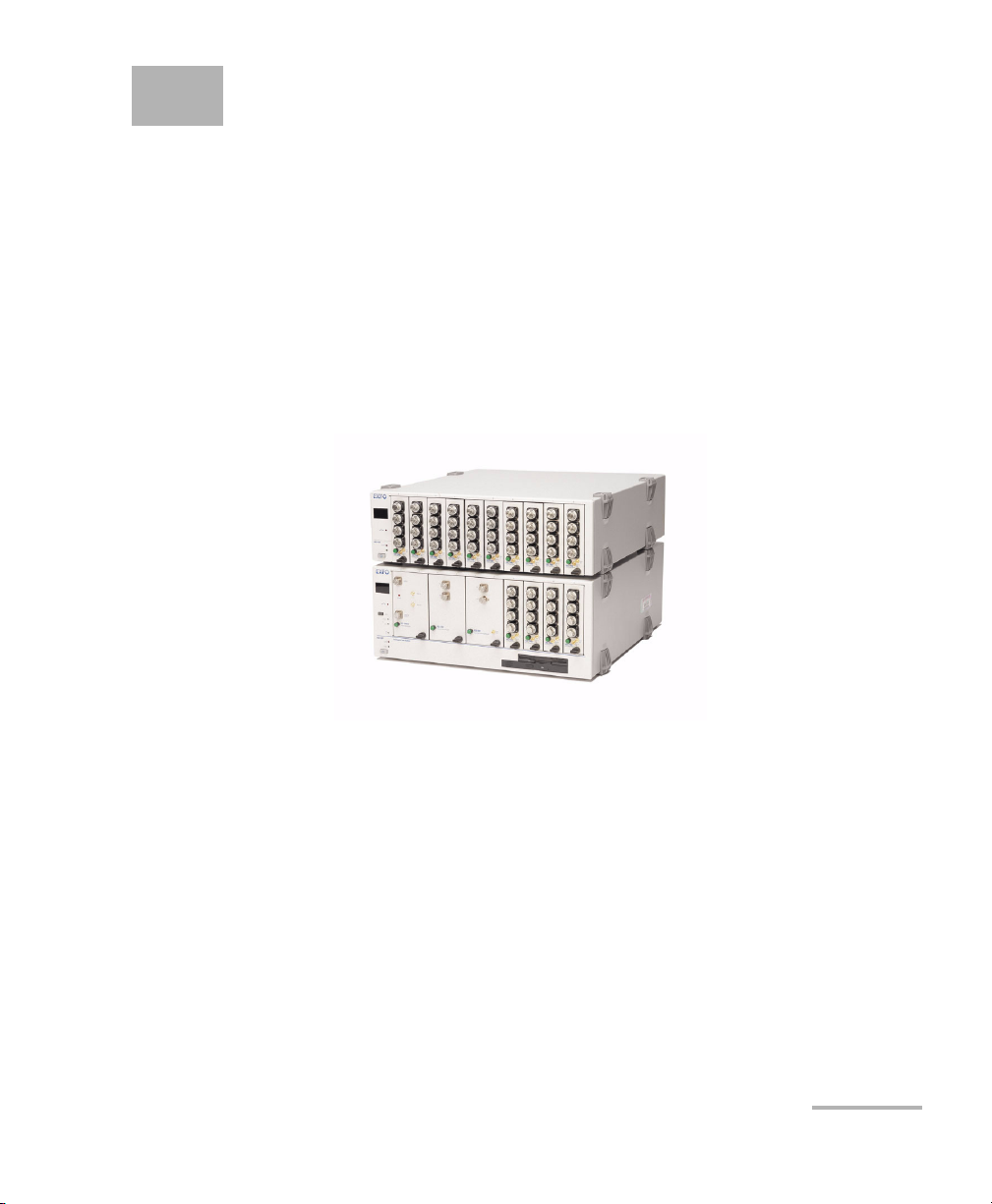
The IQS-12004B DWDM Passive Component Test System, an automated
test solution for component manufacturers and system integrators, consists
of a series of IQS modular test and measurement instruments that are
completely integrated by an off-the-shelf software application. This
revolutionary system rapidly analyzes important parameters to help you
improve your production efficiency and decrease your product time to
market.
Characterization of multiplexers, demultiplexers, filters, and other passive
components is a critical step in ensuring the optimum performance of a
wavelength-division multiplexing (WDM) system.
DWDM Passive Component Test System 1
Page 14

Introducing the IQS-12004B DWDM Passive Component Test System
Step-by-Step Approach
The system performs DWDM component characterization and measures
insertion loss, spectral uniformity, bandwidth, crosstalk, channel central
wavelength, polarization dependence and optical return loss
measurements on multiplexers, demultiplexers, filters, and other passive
devices. These parameters must be controlled and tested throughout the
entire life cycle of a component, from research and development through
to production and even deployment.
The rapidity of the test procedure is achieved by scanning a very-low-noise
tunable laser source (in this case the IQS-2600B or IQS-2600CT Tunable
Laser Source) across the DUT’s spectral band while power is measured
simultaneously on all device ports. Due to the medium coherence and
unmatched sidemode suppression of the IQS-2600B/IQS-2600CT, a
dynamic range of nearly 60 dB is easily attained.
The standard configuration includes IL and ORL measurements. Adding
the IQS-5150 PSA will enable you to perform PDL measurements.
Step-by-Step Approach
Guided by your selection parameters, the software based on Windows
2000 controls the test procedure from start to finish. This systematic
approach eliminates the possibility of data entry and reporting errors, and
avoids costly procedural mistakes. In addition, time-saving features such as
Pass/Fail testing, filter masks and a part number database simplify the job
of DWDM component characterization.
2 IQS-12004B
Page 15

Introducing the IQS-12004B DWDM Passive Component Test System
Test Features and Results
Test Features and Results
Each test step may be accessed either automatically or manually.
Complete results are calculated at the end of the scan and are available
both graphically and in a data table; values outside the defined test limits
are highlighted. All data is saved to a database for archiving and future
display or printing.
Create as many port types as you require. Once defined, they will be used
to build a database of part numbers, enabling you to quickly reconfigure
parameters simply by selecting the appropriate part number. The
parameters in the port mask are used in the automatic Pass/Fail analysis.
Modularity and Flexibility
The system is built with the future in mind; the modular nature of the
hardware and the flexibility of the software make it easy for you to upgrade
or expand your test station. A single-channel system for measuring filters or
gratings can be expanded to 32, 64, or more channels by simply adding the
necessary plug-in modules. The system is also very compact: an entire
16-channel system, including PDL, will fit into a 4U (standard rackmount
units) rackmount space.
DWDM Passive Component Test System 3
Page 16
Introducing the IQS-12004B DWDM Passive Component Test System
System Overview
System Overview
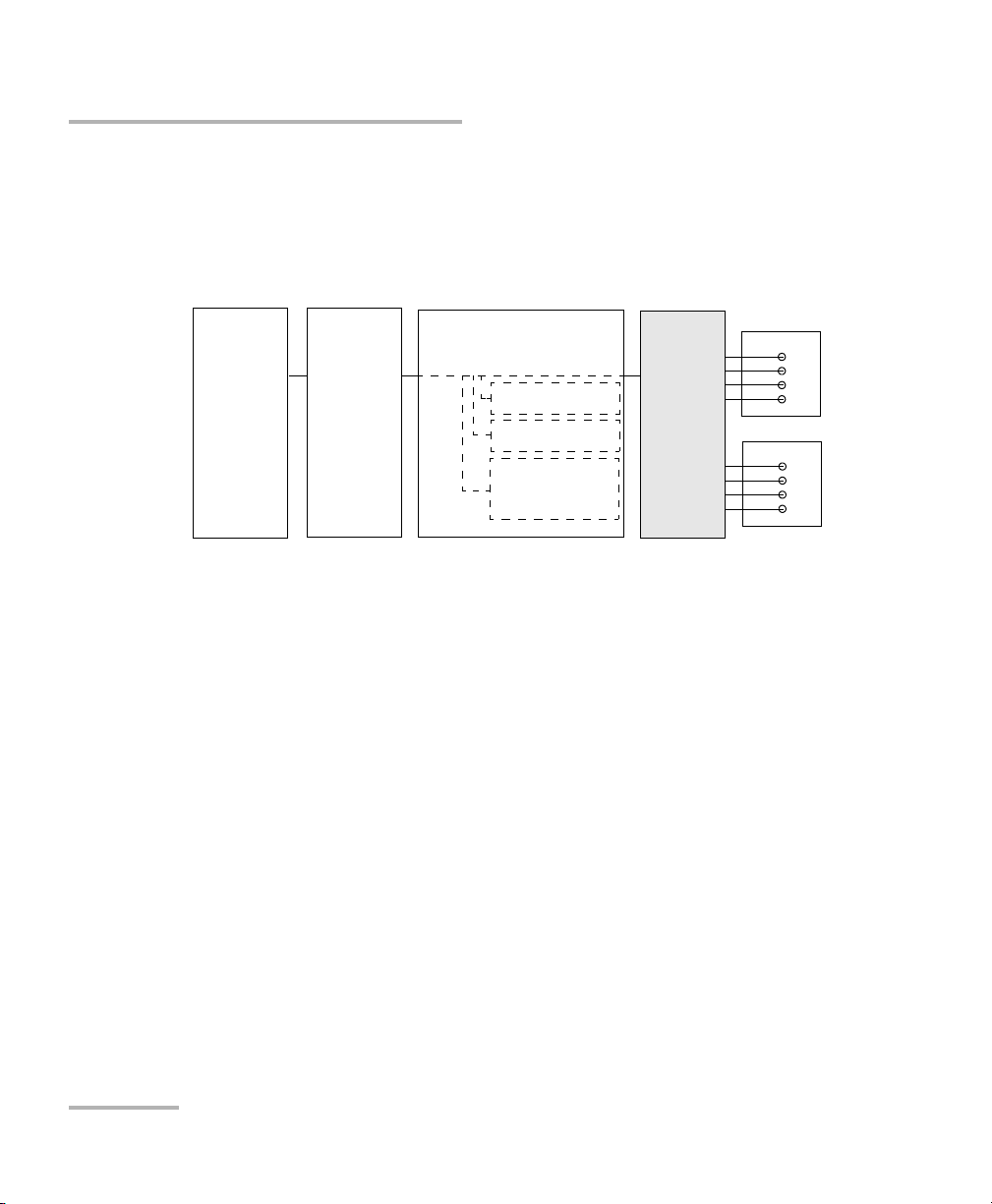
The IQS-12004B DWDM Passive Component Test System provides spectral
insertion loss (IL), polarization-dependent loss (PDL), and optical return
loss (ORL) measurements with high resolution and accuracy.
IQS-2600B
or
IQS-2600CT
Tunable
Laser
Source
IQS-5150
Polarization
State
Adjuster
IQS-9401
Wavelength Reference
Module
Power Reference
ORL
Wavelength
Reference
Device
Under Test
IQS-1643T
IQS-1643T
The DWDM Passive Component Test System sweeps a very-low-noise
tunable laser source across the spectral band of interest (C-band or
C+L-band). While the source is sweeping, synchronized measurements
from the Wavelength Reference Module (WRM) and the measurement
power meters are acquired into the system software. At the end of the
sweep, advanced signal processing is applied to the data, resulting in
accurate IL, PDL, and ORL data.
This configuration ensures quick testing time that is practically
independent of the number of device ports (there is a nominal data
transfer and analysis penalty per channel). Because of the low source
spontaneous emissions (SSE) of the IQS-2600B/IQS-2600CT Tunable Laser
Source, a dynamic range of 60 dB is easily attained. The wavelength
reference module ensures wavelength and loss accuracy by providing
a fast and continuous wavelength and power reference throughout the
sweep.
The numerous software features are explained later in this user guide.
4 IQS-12004B
Page 17

Introducing the IQS-12004B DWDM Passive Component Test System
Testin g M a n y D e vices with the MultiPath Testing Option
Testing Many Devices with the MultiPath
Testing Option
With the MultiPath Testing Option, you will be able to use the standard
IQS-12004B DWDM Passive Component Test System along with an optical
switch to perform tests on one or many DUTs with a variable number of In
ports and Out ports.The MultiPath Testing Option provides:
³ A LabVIEW application that can be either used as is to perform
references, calibrations and tests, or can be tailored to your needs.
³ COM objects offering all the necessary properties and methods to build
your own multipath software.
The MultiPath Testing Option can be used for:
³ Environmental testing of DWDM passive components.
³ Testing arrayed components like variable optical attenuators (VOAs).
³ Testing multiplexers (IL, ORL, PDL, directivity).
³ Testing optical cross-connections (OXC) and other switches.
DWDM Passive Component Test System 5
Page 18

Introducing the IQS-12004B DWDM Passive Component Test System
Hardware Components Description
Hardware Components Description
Module Usage
IQS-510P Controller Unit Controls the measurement process as well as data
interpretation and storage. The controller unit is supplied
with the necessary equipment for connection to a local
area network (LAN). For more information, refer to the
IQS-500 Intelligent Test System user guide.
IQS-510E Expansion Units Houses the instruments required by the system. If
necessary, a maximum of nine expansion units may be
connected to the controller unit. For more information,
refer to the IQS-500 Intelligent Test System user guide.
IQS-2600B or IQS-2600CT
Tunable Laser Source
IQS-1643 Power Meter Allows DWDM filters and multiplexers characterization.
IQS-5150 Polarization State
Adjuster (optional)
GPIB-controlled switch
(optional)
For more information, refer to the IQ-2600 user guide or
IQS-2600B Tunable Laser Source user guide.
For more information, refer to the IQS-1600 High-Speed
Power Meter user guide.
Allows PDL measurements.
Allows to use the MultiPath Testing Option to perform
tests on one or many DUTs with a variable number of In
ports and Out ports.
6 IQS-12004B
Page 19

Introducing the IQS-12004B DWDM Passive Component Test System
Tunable L aser Source
Tunable Laser Source
EXFO has modified its IQS-2600B Tunable Laser Source in order to
integrate it into the IQS-12004B DWDM Passive Component Test System. To
optimize the performance of the system, the optical attenuator which
ensures a constant power output from the tunable laser source has been
removed.
You can easily identify which tunable laser source you have. The unit
designed for the DWDM Passive Component Test System bears the
mention 2600CT, while the standalone unit bears the mention 2600B.
Every customer purchasing the IQS-12004B DWDM Passive Component
Test System for applications covering both the C- and L-bands will receive
an IQS-2600CT model. Even though the tunable laser source has been
modified, it can still be used as a standalone instrument using an IQS-500
Intelligent Test System.
However, you will notice a warning message when turning the instrument
on. This warning informs you that the automatic level control (ALC) is
disabled. Also note that the power stability and repeatability values
presented in the IQS-2600B specification sheet do not apply to the
IQS-2600CT.
Any other functionality or specification, particularly those concerning the
accuracy of the instrument and wavelength stability, will not be affected by
this design change.
DWDM Passive Component Test System 7
Page 20
Introducing the IQS-12004B DWDM Passive Component Test System
Module Description
Module Description
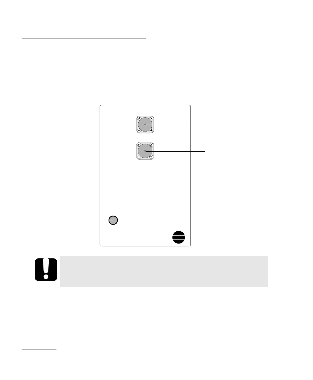
This section describes the IQS-9401 Wavelength Reference Module and the
IQS-5150 Polarization State Adjuster. For a description of the other modules
used in the DWDM Passive Component Test System, refer to the modules’
user guides.
LED push button
lights up when the
controller unit is
turned on
In order to keep the optical ports clean, the protective caps should
always be installed when the module is not being used.
IN
OUT
IQS-5150
Polarization State Adjuster
IMPORTANT
Input port,
UPC connector
Output port,
UPC connector
Retaining screw knob
8 IQS-12004B
Page 21

Introducing the IQS-12004B DWDM Passive Component Test System
Testin g Pro c e d u r e
Testing Procedure
The IQS-12004B DWDM Passive Component Test System prompts the
operator to perform a series of steps, after which it controls the different
IQS modules to perform measurements on a device under test (DUT).
The testing procedure used by the system is outlined below.
³ You can configure different test parameters in the Setup step.
³ System calibration is performed the first time the system is used. It can
also be performed as needed. Calibration comprises three elements:
detector null measurement of power meters and the WRM,
wavelength response calibration, and return loss calibration.
³ IL/PDL and ORL reference measurements are required each time the
system is turned on and are recommended whenever there is a
significant change in environmental conditions.
³ The measurement scan(s) is performed. The insertion loss (IL)
measurement requires one scan, the IL/PDL measurement requires
four scans, and the ORL measurement requires one scan.
³ At the end of the scan(s), the results are calculated and analyzed. You
can view the results and print reports as required.
DWDM Passive Component Test System 9
Page 22
Introducing the IQS-12004B DWDM Passive Component Test System
Testin g Pro c e d u r e
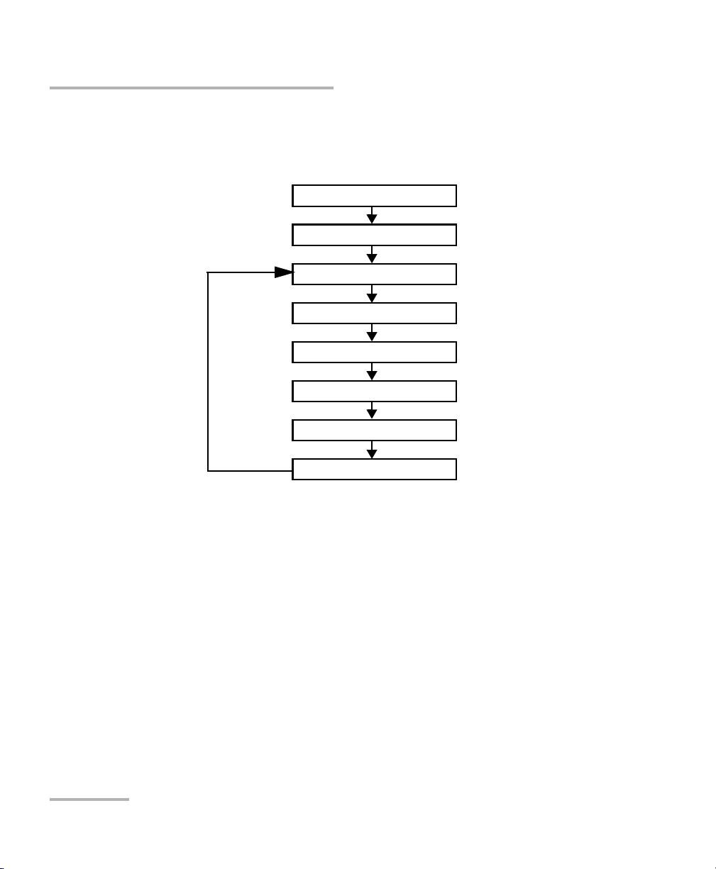
Once a supervisor has configured the IQS-12004B DWDM Passive
Component Test System, a typical test sequence would be similar to the
flow chart shown below.
Open database
Perform a reference
Select DUT
Connect DUT
Measure
View results
Print report
Test another component
10 IQS-12004B
Page 23
Introducing the IQS-12004B DWDM Passive Component Test System
Database Structure
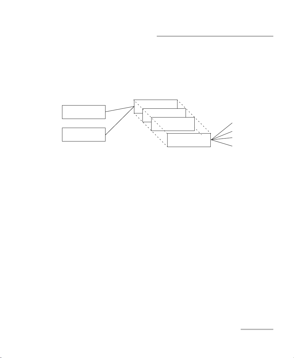
Database Structure
The IQS-12004B DWDM Passive Component Test System uses several
different databases for storing test results and configuration information.
You have full control over the results database file name and location. The
database structure is organized as shown below.
Customer.MDB
DUTPort.MDB
Results1.MDB
Results2.MDB
Results3.MDB
ResultsN.MDB
Scan data files
Scan data files
Scan data files
Scan data files
To save test results for later analysis, the IQS-12004B DWDM Passive
Component Test System uses three databases:
³ Customer.MDB: This database contains information about your
customers. It is managed internally by the system.
³ DUTPort.MDB: This database contains Pass/Fail information about the
devices that you want to test. It is managed internally by the system.
³ ResultsN.MDB: This database contains test results. You can create as
many files as you want. For example, it might be practical to have
different files for different customers, components, or test sessions.
Basically, the system has built-in flexibility to let you choose the best
way of saving test results.
DWDM Passive Component Test System 11
Page 24

Introducing the IQS-12004B DWDM Passive Component Test System
Using GPIB or COM to Control the System
The IQS-12004B DWDM Passive Component Test System also uses scan
data files. These files are the test results data files containing the IL vs. λ,
PDL vs. λ, and ORL vs. λ data. These files are created and managed by the
DWDM Passive Component Test System. They are saved only if Save
Results Curves is selected in the System Settings window.
When you create a new database in the system, you are creating only a
new ResultsN database. The customer and DUT information that you
previously entered in the first two databases (Customer and DUTPort) will
be available for the new ResultsN database.
If you need information or details about the database structure, please
contact EXFO (see Contacting the Technical Support Group on page 223).
Using GPIB or COM to Control the System
The IQS-12004B DWDM Passive Component Test System gives you the
opportunity to develop your own applications using either SCPI commands
(GPIB control) or COM objects.
The MultiPath Testing Option allows you to develop your tailored
applications using COM objects.
In order to be able to take IL, ORL, and PDL measurements with the
standard DWDM Passive Component Test System or the MultiPath Testing
Option, there are a number of required steps and procedures to follow.
12 IQS-12004B
Page 25
Introducing the IQS-12004B DWDM Passive Component Test System
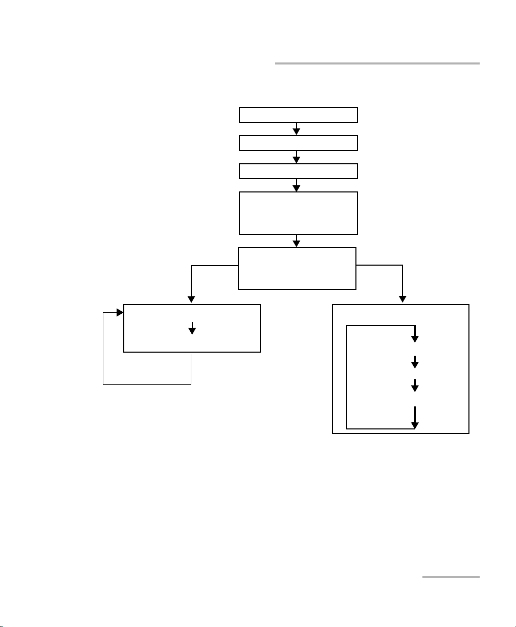
A typical test sequence would be similar to the flow chart below.
Standard IQS-12004B
DWDM Passive
Component Test System
(one DUT at a time)
Using GPIB or COM to Control the System
Initialize hardware
Null power meter
Optimize power
Calibrate system
IL/PDL
ORL
Reference system
IL/PDL
ORL
MultiPath Testing
option (possibility of
several DUTs at a time)
Te s t D UT
Retrieve results
Tes t D UT
h
c
t
i
Select input port
w
s
e
h
t
Measure/analyze
g
n
i
s
u
g
n
i
l
c
y
C
Retrieve data
Each time a new test sequence is started, the above steps are required or
highly recommended. In some cases, the system will generate error
messages where the prerequisite steps have not been performed.
DWDM Passive Component Test System 13
Page 26

Introducing the IQS-12004B DWDM Passive Component Test System
Conventions
Conventions
Before using the product described in this manual, you should understand
the following conventions:
WARNING
Indicates a potentially hazardous situation which, if not avoided,
could result in death or serious injury. Do not proceed unless you
understand and meet the required conditions.
CAUTION
Indicates a potentially hazardous situation which, if not avoided,
may result in minor or moderate injury. Do not proceed unless you
understand and meet the required conditions.
CAUTION
Indicates a potentially hazardous situation which, if not avoided,
may result in component damage. Do not proceed unless you
understand and meet the required conditions.
IMPORTANT
Refers to information about this product you should not overlook.
14 IQS-12004B
Page 27
2 Safety Information
Laser Safety Information
WARNING
Do not install or terminate fibers while a light source is active.
Never look directly into a live fiber and ensure that your eyes are
protected at all times.
WARNING
Use of controls, adjustments and procedures for operation and
maintenance other than those specified herein may result in
hazardous radiation exposure.
Safety Information
Your instrument is a Class 1 laser product in compliance with standards
IEC 60825-1 Amendment 2: 2001 and 21 CFR 1040.10. Laser radiation may
be encountered at the output port.
The following label indicates that a product contains a Class 1 source:
CLASS 1
LASER PRODUCT
Note: Label shown for information purposes only. It is not affixed to your product.
The DWDM Passive Component Test System may be equipped with the
IQS-2600B or the IQS-2600CT tunable laser sources. For more information
on these modules, refer to the IQS-2600B Tunable Laser Source user guide.
DWDM Passive Component Test System 15
Page 28

Page 29

3 Getting Started with Your
DWDM Passive Component
Test System
This chapter contains a description of hardware components and modules
used in the system, information on how to install hardware components
and how to install and start the IQS-12004B DWDM Passive Component
Test System software. You will also find a description of the utility to
organize test files as well as a description of the application main window.
Inserting and Removing Test Modules
CAUTION
Never insert or remove a module while the controller unit and its
expansion units are turned on. This will result in immediate and
irreparable damage to both the module and unit.
To insert a module into the controller or expansion unit:
1. Exit IQS Manager and turn off all your units.
2. Remove the protective cover from the desired unused module slot.
2a. Pull the retaining screw knob firmly towards you and release the
bottom of the cover.
2b. Gently pull the top of the protective cover downwards, to remove
it from the unit grooves.
DWDM Passive Component Test System 17
Page 30
Getting Started with Your DWDM Passive Component Test System
Inserting and Removing Test Modules
Protective cover
Retaining screw
knob
2a
2b
3. Position the module so that its front panel is facing you and the top and
bottom protruding edges are to your right.
4. Insert the protruding edges of the module into the grooves of the unit’s
module slot.
Protruding edges
(right side of module)
5
Retaining screw knob
Retaining screw
18 IQS-12004B
Page 31

Getting Started with Your DWDM Passive Component Test System
Inserting and Removing Test Modules
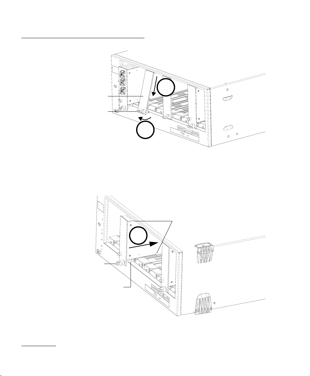
5. Push the module all the way to the back of the slot, until the retaining
screw makes contact with the unit casing.
6. While applying slight pressure to the module, turn the retaining screw
knob (located at the bottom of the panel) clockwise until the knob is
horizontal. This will secure the module into its “seated” position.
6
The module is correctly inserted when its front panel is flush with the front
panel of the controller or expansion unit.
When you turn on the controller unit, the startup sequence will
automatically detect your module.
Note: You can insert IQ modules into your controller or expansion unit; the IQS
Manager software will recognize them. However, the IQS-500 locking
mechanism (retaining screw) will not work for IQ modules.
To remove a module from your controller or expansion unit:
1. While pulling gently on the knob, turn it counterclockwise until it stops.
The module will slowly be released from the slot.
DWDM Passive Component Test System 19
Page 32

Getting Started with Your DWDM Passive Component Test System
Inserting and Removing Test Modules
Retaining screw knob
2. Place your fingers underneath the module or hold it by the retaining
screw knob (NOT by the connector) and pull it out.
Connector
NO
YES
Retaining screw
knob
20 IQS-12004B
Page 33

Getting Started with Your DWDM Passive Component Test System
Inserting and Removing Test Modules
CAUTION
Pulling out a module by a connector could seriously damage both
the module and connector. Always pull out a module by the
retaining screw knob.
3. Cover empty slots with the supplied protective covers. Simply slide the
top of the protective cover into the upper grooves of the unit, and then
snap into place by pushing the retaining screw knob.
CAUTION
Failure to reinstall protective covers over empty slots will result in
ventilation problems.
DWDM Passive Component Test System 21
Page 34

Getting Started with Your DWDM Passive Component Test System
Installing Hardware Components
Installing Hardware Components
The DWDM Passive Component Test System has been configured and
tested at the factory, under normal conditions, and installed by an EXFO
authorized installation engineer. The following information is provided in
the event that it is necessary to move, transport, or reinstall the system.
Controller and Expansion Units
Please refer to the IQS-500 Intelligent Test System user guide for detailed
information about installing and connecting the controller and expansion
unit(s).
Source, Wavelength Reference, and PSA
The source (IQS-2600B or IQS-2600CT), the wavelength reference module
(IQS-9401), and the optional polarization state adjuster (IQS-5150) must be
installed in the same expansion unit and in a specific order.
The recommended configurations are presented hereafter.
CAUTION
Never insert or remove a module while the controller or expansion
unit is turned on. This will result in immediate and irreparable
damage to both the module and unit.
22 IQS-12004B
Page 35

Getting Started with Your DWDM Passive Component Test System
Installing Hardware Components
Configuration with PDL
Connect the tunable output of the IQS-2600B/IQS-2600CT to the input of the
IQS-5150 using the rigid patchcord supplied with the
IQS-2600B/IQS-2600CT. Connect the output of the IQS-5150 to the input of
the IQS-9401, as illustrated below.
IN
OUT
IQS-9401
Wavelength Reference Module
Sync
Out
ACTIVE
IQS-2600CT
Tunable Laser Source
OUTPUT
MONITOR
OUTPUT
TRIG IN
TRIG OUT
IN
OUT
IQS-5150
Polarization State Adjuster
Connect the launch fiber to the output of the IQS-9401.
Note: The IQS-9401 has an angled (APC) output connector.
DWDM Passive Component Test System 23
Page 36

Getting Started with Your DWDM Passive Component Test System
Installing Hardware Components
Configuration without PDL
Connect the tunable output of the IQS-2600B/IQS-2600CT to the input of the
IQS-9401 using the rigid patchcord supplied with the tunable source, as
illustrated below.
IN
OUT
IQS-9401
Wavelength Reference Module
Sync
Out
ACTIVE
IQS-2600CT
Tunable Laser Source
OUTPUT
MONITOR
OUTPUT
TRIG IN
TRIG OUT
Connect the launch fiber to the output of the IQS-9401.
Note: The IQS-9401 has an angled (APC) output connector.
24 IQS-12004B
Page 37

Getting Started with Your DWDM Passive Component Test System
Installing Hardware Components
Configuration of Power Meters
The IQS-1643T power meters must be installed sequentially in the unit. Use
the short synchronization cables to connect power meters in the same
unit, and the long synchronization cables to connect power meters in
different units. It is also necessary to install a synchronization cable
between the IQS-9401 and the first power meter, as illustrated below.
ACTIVE
IQS-2600CT
Tunable Laser Source
OUTPUT
MONITOR
OUTPUT
TRIG IN
TRIG OUT
IN
OUT
IQS-5150
Polarization State Adjuster
IN
OUT
IQS-9401
Wavelength Reference Module
SYNC OUT
C
F
-
T
T
N
C1
X
F
O
C2
C3
C4
Sync
Out
IQS-1600T
4-Ch Power Meter
Sync In
Trig
SYNC IN
C
F
-
T
T
N
C1
E
Sync
Out
C2
C3
C4
IQS-1600T
4-Ch Power Meter
X
F
O
Sync In
Trig
C
F
-
T
T
N
C1
E
Sync
Out
C2
C3
C4
IQS-1600T
4-Ch Power Meter
X
F
O
Sync In
Trig
C
F
-
T
T
N
C1
E
C2
C3
C4
Sync
Out
IQS-1600T
4-Ch Power Meter
IMPORTANT
The power meters must be correctly installed and configured before
starting IQS Manager or before turning the unit on. If modules need
to be repositioned, you will have to restart the system.
IMPORTANT
To keep the optical ports clean, ensure that protective caps are
always installed when the module is not being used.
E
X
F
O
Sync
Out
Sync In
Trig
DWDM Passive Component Test System 25
Page 38

Getting Started with Your DWDM Passive Component Test System
Installing Hardware Components
To work with the MultiPath Testing Option, you will have to add a switch to
your standard IQS-12004B DWDM Passive Component Test System to
benefit from its inherent features.
CAUTION
Never insert or remove a module while the controller or expansion
unit is turned on. This will result in immediate and irreparable
damage to both the module and unit.
The minimum hardware components required for multipath testing are:
³ Tunable laser source (IQS-2600B or IQS-2600CT).
³ Wavelength reference module (IQS-9401).
³ Power meter (IQS-1643T), one or more.
³ Switch (either the IQS-9100, or a GPIB-controlled switch. Check with
EXFO to see if a specific model is supported.).
Regardless of whether you will be using an EXFO switch or any of the
supported switches, the connection of the switch in the system will remain
the same.
The switch has to be connected to the Wavelength Reference Module ()
and to the power meters. Use the supplied to link the Out port of the WRM
to the common port of the switch. Connect the DUT(s) between the power
meter and the switch.
26 IQS-12004B
Page 39

Getting Started with Your DWDM Passive Component Test System
Installing Hardware Components
To work in high-power mode, you will have to add a switch and an EDFA
to your standard IQS-12004B DWDM Passive Component Test System.
IMPORTANT
In order to be able to control the EDFA, the GPIB address of the
EDFA must be smaller than the GPIB address used for the switch.
CAUTION
Never insert or remove a module while the controller or expansion
unit is turned on. This will result in immediate and irreparable
damage to both the module and unit.
The minimum hardware components required for multipath testing in high
mode are:
³ Tunable laser source (IQS-2600B or IQS-2600CT).
³ Wavelength reference module (IQS-9401).
³ Power meter (IQS-1643T), one or more.
³ The KPS-AMP-C-20 fiber amplifier (EDFA).
³ A high-power GPIB-controlled switch.
DWDM Passive Component Test System 27
Page 40

Getting Started with Your DWDM Passive Component Test System
Installing the IQS-12004B DWDM Passive Component Test System Software
Installing the IQS-12004B DWDM Passive
Component Test System Software
For the DWDM Passive Component Test System to function properly, the
IQS Manager software must be installed on your IQS-500 Intelligent Test
System.
Normally, you wouldn’t have to install the IQS Manager software or the
DWDM Passive Component Test System software, except in particular
circumstances (such as after having reinstalled Microsoft Windows).
For information on installing IQS Manager software, refer to the IQS-500
Intelligent Test System user guide.
To install the DWDM Passive Component Test System on an
IQS-500 controller unit:
1. Insert CD of the DWDM Passive Component Test System in the CD-ROM
drive.
2. Select Run from the Windows Start menu.
3. Ty pe F:\ setup.exe in the Open text field.
4. Click OK to start the wizard and follow the on-screen instructions.
28 IQS-12004B
Page 41

Getting Started with Your DWDM Passive Component Test System
Installing the MultiPath Testing Option Software
Installing the MultiPath Testing Option
Software
Before installing the MultiPath Testing Option software, ensure that the
IQS-12004B DWDM Passive Component Test System software has been
installed on the IQS-500 controller unit. For more information, see Installing
the IQS-12004B DWDM Passive Component Test System Software on
page 28.
To install the MultiPath Testing software on an IQS-500 controller
unit:
1. Insert the MultiPath Testing software CD-ROM in the drive.
2. Select Run from the Windows Start menu. The Run window appears.
3. Use the Browse button to find the setup.exe file on the CD-ROM.
4. Click OK to start the installation.
EXFO recommends that you keep the default names and paths suggested
by the setup program.
Follow the on-screen instructions. Once the LabVIEW demo is installed,
the installation of the files required to run LabVIEW will begin.
DWDM Passive Component Test System 29
Page 42

Getting Started with Your DWDM Passive Component Test System
Installing the MultiPath Testing Option Software
If the following dialog box appears, that means that LabVIEW has been
installed in a previous session.
If this is the case, choose Modify, click Next and follow the on-screen
instructions.
IMPORTANT
Selecting an option other than Modify may prevent the MultiPath
Test i ng Op t ion software from working properly.
For information on how to use the MultiPath Testing Option application, see
Testing Multiple DUTs with the LabVIEW Application on page 117.
30 IQS-12004B
Page 43

Getting Started with Your DWDM Passive Component Test System
Starting and Exiting the DWDM Passive Component Test System Application
Starting and Exiting the DWDM Passive
Component Test System Application
To start the DWDM Passive Component Test System application:
³ On the Windows taskbar, click Start, select Programs > EXFO >
IQS-12004B > IQS-12004B DWDM Test System.
OR
³ Double-click the IQS-12004B DWDM Test System desktop icon.
To exit the DWDM Passive Component Test System application:
Select Exit from the File menu.
At the starting of the application, a message may appear, indicating that the
regional settings of your system were temporary changed. This change
consists in using a period for the decimal symbol and using the
YYYY-MM-DD date style.
DWDM Passive Component Test System 31
Page 44

Getting Started with Your DWDM Passive Component Test System
Starting and Exiting the DWDM Passive Component Test System Application
By default, the Welcome/New Test window appears first when you start the
DWDM Passive Component Test System (see Opening a New Test
Database on page 61).
The Welcome/New Test window gives you the possibility to open a new
test database, to open an existing test database, or to view the content of
recent test databases.
32 IQS-12004B
Page 45

Menu bar
Getting Started with Your DWDM Passive Component Test System
Starting and Exiting the DWDM Passive Component Test System Application
Clicking Cancel takes you to the application main window, as shown on
the figure below.
The DWDM Passive Component Test System main window is the central
location from where you access all functionalities.
Title bar
Function
buttons
Position of
modules in
IQS unit
Status bar
Details the procedure
in progress
DWDM Passive Component Test System 33
Page 46

Getting Started with Your DWDM Passive Component Test System
Accessing a Specific Test Step
Accessing a Specific Test Step
During the step-by-step procedure, it is possible to access the Te s t Steps
dialog box to manually go to a specific step via the Step button from the
main window.
To p r o cee d w ith
the current step
To s k i p th e
current step
34 IQS-12004B
Page 47

Getting Started with Your DWDM Passive Component Test System
Starting and Exiting the MultiPath Testing Option Application
Starting and Exiting the MultiPath Testing
Option Application
You may want to use the provided LabVIEW application to work with the
MultiPath Testing option .
To start the LabVIEW application:
³ On the Windows taskbar, click Start, select Programs > EXFO >
IQS-12004B > IQS-12004B Multi Path DWDM Test System.
OR
³ Double-click the IQS-12004B MPT desktop icon.
The application main window is displayed.
To close the application, select Exit from the File menu.
DWDM Passive Component Test System 35
Page 48

Page 49

4 Setting Up the DWDM Passive
Component Test System
The DWDM Passive Component Test System has been designed to let you
define DUTs and optical ports that can be used for future tests.
Configuring DUT Parameters for Pass/Fail Analysis
Note: You must be working at the Supervisor level to access this window.
The DUT Configuration window allows you to define specific parameters
for the optical ports and DUTs you will be testing. Information entered in
this window is used to construct and maintain two internal lists: one for
port types and one for DUTs. These two lists provide an efficient way of
identifying the Pass/Fail limits for all your commonly tested components.
The relationship between optical ports and DUTs is illustrated below. In this
example, the DUT is a four-channel device with one common port and four
output ports.
Port 1 (200 GHz bandpass)
1x4 Demultiplexer
(DUT)
To identify the Pass/Fail criteria for this type of component, you must define
the different parameters (IL, PDL, BW, etc.) for each port. In most cases,
the characteristics for all ports will be identical, except for the wavelength.
The most efficient way of describing the above device would be to create a
port (200 GHz bandpass) and define all its Pass/Fail criteria. When you
define the DUT, you simply have to select a port type for each output and
assign a wavelength to the port mask. This 200 GHz bandpass port will also
be used for defining other devices. There is no practical limit to the number
of different ports or DUTs that can be defined.
DWDM Passive Component Test System 37
Port 2 (200 GHz bandpass)
Port 3 (200 GHz bandpass)
Port 4 (200 GHz bandpass)
Page 50

Setting Up the DWDM Passive Component Test System
Configuring DUT Parameters for Pass/Fail Analysis
This window can be accessed via the Configure DUTs icon from the
Welcome/New Test window. For information on how to display this
window, see Opening a New Test Database on page 61.
³ Optical Ports Configuration: This section contains the list of all
configured ports. You can add new ports (click Add), modify the port
indicated in the Port Type list box (click Modify), or delete an existing
optical port (click Delete).
For information about the configuration of an optical port type, see
Configuring an Optical Port on page 39.
³ DUT Configuration: This section allows you to configure DUTs based
on the optical port types. You can add new DUTs (click Add), modify
the DUT indicated in the Part Number list box (click Modify), or delete
an existing DUT (click Delete).
For information about the configuration of a DUT, see Configuring a
DUT on page 42.
38 IQS-12004B
Page 51

Setting Up the DWDM Passive Component Test System
Configuring an Optical Port
Configuring an Optical Port
Note: You must be working at the Supervisor level to access this window.
This window can be accessed via the Configure DUTs icon from the
Welcome/New Test window. For information on how to display this
window, see Opening a New Test Database on page 61.
When you click Add or Modify in the Optical Ports Configuration section,
the following window appears where you can enter or modify port
information. For details about the parameters contained in this window,
see Definitions and Calculation Methods on page 405.
Note: Some parameters can be disabled (grayed out) when you select a certain
mask type.
³ Port Type: Use this text box to give a unique name to the optical port
defined.
³ Mask Type: This list box allows you to select one of two different mask
types (bandpass and notch).
DWDM Passive Component Test System 39
Page 52

Setting Up the DWDM Passive Component Test System
Configuring an Optical Port
The Spectral Parameters section is used to specify the limits or the
acceptable values that will determine the Pass/Fail result of the tests.
³ BW1, BW2, and BW3: These text boxes allow you to specify the relative
power levels (in dB) at which bandwidth is tested, and the acceptable
bandwidth (in nm). Note that only BW2 and BW3 are tested when the
Defined Bandwidth calculation method is selected.
³ BWx Tolerance: These text boxes allow you to specify the tolerance
interval for the bandwidth test. For a DUT to pass this test, the
measured BWx value must fall within BWx ±BWx tolerance.
³ Wavelength Tolerance: This text box is used to enter the central
wavelength tolerance of the specified port. This test is not performed
when the Defined Bandwidth calculation method is selected.
The Loss Parameters section is used to specify the flatness, crosstalk,
rejection as well as the IL, ORL and PDL values.
³ Flatness: This text box is used to enter the acceptable flatness (in dB)
of the curve in the measured BW1 interval.
³ Crosstalk: This text box allows you to enter the acceptable channel
crosstalk (in dB) for the DUT. This option is disabled (grayed out) when
the notch mask type is selected.
³ Rejection: This text box allows you to enter the acceptable rejection
level (in dB) for the DUT. This option is disabled (grayed out) when the
bandpass mask type is selected.
³ IL: This field allows you to specify the acceptable insertion loss value
(dB).
³ ORL: This field allows you to specify the ORL limit value (dB).
³ PDL: This field allows you to specify the PDL limit value (dB).
40 IQS-12004B
Page 53

Setting Up the DWDM Passive Component Test System
Configuring an Optical Port
The Calculation Method Based On section is used to select which
method will be used to calculate some of the different test results. For
details about these methods, see Definitions and Calculation Methods on
page 405.
³ Measured Bandwidth: This option allows BW1 to be determined from
the measured data.
³ Defined Bandwidth: This option allows you to define BW1 yourself.
When selecting defined bandwidth, you will enter the defined
bandwidth in the BW1 box. During the data analysis, the software will
use the CW ±BW1/2 as the analysis range for IL, crosstalk, ripple, etc.
DWDM Passive Component Test System 41
Page 54

Setting Up the DWDM Passive Component Test System
Configuring a DUT
Configuring a DUT
Note: You must be working at the Supervisor level to access this window.
This window can be accessed via the Configure DUTs icon from the
Welcome/New Test window. For information on how to display this
window, see Opening a New Test Database on page 61.
Once the optical ports are correctly defined, you can configure DUTs based
on these ports. When clicking Add or Modify in the DUT Configuration
section, the following window appears where you can enter or modify
information about the DUT.
In the upper section of the DUT Configuration window, you enter
identification and test parameters. These parameters will automatically be
selected when performing a scan on a defined device.
Note: Once a device has been created, the Number of Ports cannot be modified.
³ Part Number: the part number for the DUT.
³ Description: a short description of the DUT.
³ Manufacturer: the name of the manufacturer.
42 IQS-12004B
Page 55

Setting Up the DWDM Passive Component Test System
Configuring a DUT
³ Analysis from X nm to Y nm: the default range of the analysis. The
analysis limits can be modified later in the IQS-12004B Setup window.
³ Number of Ports: the number of ports, excluding the common port.
³ Port Number: In this list box, you select the port for which you will
configure the type and central wavelength. You can also use the
Previous and Next buttons to move from one port to another.
³ Port Type: In this list box, you select the type of port from the list of
available ports that you configured previously. Usually for a device, all
ports are of the same type, but this is not always the case; and the
software allows you to configure devices with different port types. For
more information, see Configuring an Optical Port on page 39.
³ Center Wavelength: You can specify a wavelength yourself (using the
Specified Wavelength option button), or select one of the ITU
wavelengths from the list (using the From List option button). The ITU
wavelength values correspond to the list defined in the Channel List
dialog. For more information, see Customizing the Channel List on
page 46.
³ ORL Analysis: Select this option to perform an ORL analysis.
³ The PDL Analysis section allows you to select options for PDL testing.
³ If you intend to export detailed IL results, check the
Keep IL traces for all states of polarization (4) box.
³ If you need to get the results from the polarization-dependent
wavelength analysis, check the
Polarization Dependent Wavelength box.
Note: These two options can also be selected when you set the test parameters.
For more information, see Preparing the Test Setup on page 49. If you omit
to check the boxes, you won’t be able to export the corresponding traces.
For more information on exporting, see Exporting Data on page 94.
³ Center Wavelength: The PDL value is taken at the central wavelength
for each port.
DWDM Passive Component Test System 43
Page 56

Setting Up the DWDM Passive Component Test System
Configuring DUT Company/Customer Parameters
³ Operating Wavelength Range: The highest PDL value in the BW1
range is taken.
³ Relative Range (CW)±X nm: allows you to indicate the highest PDL
value in the relative range ± X nm.
³ From X nm to Y nm: allows you to indicate the highest PDL value
between X nm and Y nm.
Click OK to add the DUT to the list of available components to test.
Configuring DUT Company/Customer
Parameters
Note: You must be working at the Supervisor level to access this window.
The Company/Customer Configuration window contains identification
and system information including the name of the company (organization
performing the tests) and the customer (organization for which the tests
are performed).
All this information is saved in a database and is useful for documentation
and traceability purposes.
To access the Company/Customer Configuration window:
From the Configuration menu, select Company/Customer
Configuration.
44 IQS-12004B
Page 57

Setting Up the DWDM Passive Component Test System
Configuring DUT Company/Customer Parameters
³ Company Information: This section indicates the name of the
company performing the tests. You can modify the information by
clicking Modify.
³ Customer List: This section allows you to enter data about the
different customers. You can add new customers to the database (click
Add), modify a customer indicated in the list box (click Modify), or
delete an existing customer (click Delete). When clicking Add or
Modify, the following window appears where you can enter or modify
customer information.
DWDM Passive Component Test System 45
Page 58

Setting Up the DWDM Passive Component Test System
Customizing the Channel List
Customizing the Channel List
Note: You must be working at the Supervisor level to use this feature.
This feature allows you to view and customize the channel list, which
contains predefined ITU wavelengths. New wavelengths can also be added
to this list. The DWDM Passive Component Test System displays the
channel list when a choice of wavelength is required.
The number of digits displayed after the decimal point can be changed to
better suit your needs.
You can access the Channel List window by selecting Channel List from
the Options menu.
To modify the number of digits displayed after the decimal point:
Use the Decimal Places box to set the desired value.
Number of digits
after decimal
point
46 IQS-12004B
Page 59

Setting Up the DWDM Passive Component Test System
Customizing the Channel List
To modify the ITU channel list display:
1. In the Channel Spacing box, select the space value (in GHz) between
the channels of the DUT.
2. In the Start Wavelength and End Wavelength boxes, enter the values
that will determine the wavelength range that will be displayed on the
list.
3. Confirm your changes with Apply.
To add a new wavelength to the list:
1. Enter the new wavelength in the Wa velength text box. The number of
decimals depends on the value set in the Decimal Places box.
2. Click Add. Your new channel will be added to the list.
DWDM Passive Component Test System 47
Page 60

Setting Up the DWDM Passive Component Test System
Customizing the Channel List
To delete wavelengths from the list:
If you want to delete a specific item, click the value you want to remove
from the wavelength list and click Remove.
OR
If you want to empty the list, click the Remove All button.
Once you are done with the changes, click OK to validate the new list or on
Cancel to discard the modifications.
48 IQS-12004B
Page 61

Setting Up the DWDM Passive Component Test System
Preparing the Test Setup
Preparing the Test Setup
Before performing a test, you have to specify the parameters to be used.
The application offers you two types of tests:
³ Generic: Useful to quickly test a DUT by using the default values
provided. Some analysis can be done with this option, but no Pass/Fail
status will be given.
³ Specified: Useful to perform a test using predefined parameters and
Pass/Fail limits. When selecting this test, the DUT Identification group
box is displayed (see Identifying the Current DUT on page 54).
You can specify the values for the scan parameters to be taken into
account during tests. These values include:
³ The number of channels to be tested: By default, the application
displays the total number of available power meter channels. However,
if you do not intend to work with all of the available channels, EXFO
recommends that you indicate the actual number of channels you are
using. This will save some testing time and a lot of disk storage space.
³ The tested wavelength range (in nm): By default, the application
displays the full range of the source in use. Changing this to a smaller
range will save disk storage space and may also reduce testing time.
DWDM Passive Component Test System 49
Page 62

Setting Up the DWDM Passive Component Test System
Preparing the Test Setup
³ The scan resolution (in pm): This parameter determines the
approximate scan resolution. The application will set the appropriate
source sweep speed and power meter sampling rate.
The application allows you to indicate the test selection:
³ PDL: calculations, based on the Mueller Matrix four-state method, take
into account the optical retardation of the polarization state adjuster
(IQS-5150).
³ Simplified PDL: faster than standard PDL (calculations do not take into
account the optical retardation of the polarization state adjuster), but
adds an uncertainty of about 5 % of the DUT PDL.
³ ORL.
You can specify the IL analysis parameters, the PDL analysis parameters
and whether the system must perform a continuous scan or not.
The DWDM Passive Component Test System performs PDL measurements
as function of wavelength. It can also keep intermediate traces for export
purposes.
The result table will be adjusted according to the options specified in the
PDL Analysis group box.
³ In addition to standard IL results (DUT IL average values), you may
need to get IL results obtained at the four states of polarization.
³ You may also need to get traces from the PDW analysis. The PDW
analysis is made using proprietary algorithms (patent pending) and is
based on calculations using the Mueller Matrix coefficients. Using data
from the four scans performed for the PDL measurement, the DWDM
Passive Component Test System analysis software internally calculates
the transmission response for many states of polarization and
generates the insertion loss curves for the extreme values.
Note: The test setup step is only available when you have already created a test.
50 IQS-12004B
Page 63

Setting Up the DWDM Passive Component Test System
Preparing the Test Setup
To set the test parameters:
1. Ensure that the IQS-12004B Setup window is open. For more
information on selecting a step, see Accessing a Specific Test Step on
page 34.
2. From the Test Ty p e group box, select Generic or Specified test.
3. From the Scan Parameters group box, specify the required
parameters.
3a. Indicate the number of power meter channels to use by typing the
value in the Channel(s) entry box.
3b. Specify the wavelength range (in nanometers) that will be used
for the analysis in the Analysis from X nm to Y nm entry boxes.
IMPORTANT
When testing “specified” devices, changing the wavelength range
parameter will override the parameter stored in the DUT database.
Note: Setting a smaller scan range will reduce the database size, the time
required for the analysis and for the scan.
3c. Select the scan resolution value (in picometers) from the
Resolution list.
Note: Resolution cannot be set to 5 pm when using the IQS-2600B source.
DWDM Passive Component Test System 51
Page 64

Setting Up the DWDM Passive Component Test System
Preparing the Test Setup
4. If you need the DWDM Passive Component Test System to perform
successive scans,
4a. Check the box from the Continuous Scan group box.
4b. Enter the number of scans you want to perform in the
corresponding text field.
5. From the Test S e l ec tion group box, check the PDL, Simplified PDL
and/or ORL boxes according to the measurements you want to
perform.
6. From the IL Analysis group box, specify the relative power levels (in
dB) at which the bandwidth is calculated (for notch and bandpass
filters).
52 IQS-12004B
Page 65

Setting Up the DWDM Passive Component Test System
Preparing the Test Setup
7. From the PDL Analysis group box, specify the required parameters.
For more information on the various parameters, see Configuring a
DUT on page 42.
Note: If you omit to check the Keep IL traces for all states of polarization (4)
box, you won’t be able to export these traces. For more information on
exporting, see Exporting Data on page 94.
Note: If you omit to check the Polarization Dependent Wavelength box, you
won’t be able to export these traces. For more information on exporting, see
Exporting Data on page 94.
8. If you selected Specified for the test type, the DUT Identification group
box is displayed. Use this section to select and identify the device that
will be tested. For more information, see Identifying the Current DUT
on page 54.
Note: At start-up, your access level is activated by default. For more information
about access levels, see Working with Access Levels on page 59.
DWDM Passive Component Test System 53
Page 66

Setting Up the DWDM Passive Component Test System
Identifying the Current DUT
Identifying the Current DUT
The DUT Identification is used to select and identify the device that will be
tested next. The DUT Identification group box is accessible from the
IQS-12004B Setup window and by selecting the Specified test type.
³ Part Number : This list box is used to select the part number of the DUT.
The available DUTs were previously created in the DUT Configuration
window. For information on DUT creation, see Configuring a DUT on
page 42.
³ Description: This text box shows the short description of the DUT
corresponding to the selected part number.
³ Customer: This list box is used to select the name of the customer
associated with the current DUT. For information on modifying the list
of customers, see Configuring DUT Company/Customer Parameters on
page 44.
³ Test e d by : This text field allows you to identify the name of the person
doing the current test.
³ Serial Number: This text field is used to identify the DUT with a serial
number. The serial number is mandatory.
³ Batch: This text field allows you to specify a batch number.
54 IQS-12004B
Page 67

Setting Up the DWDM Passive Component Test System
Identifying the Current DUT
Two buttons are available on the right side of the window to enter and view
additional information about the DUT.
³ Show Limits: This button will open the Optical Port Limits window
(see figure below), where you can see different limits of the current
DUT. These parameters were set in Supervisor level on the DUT
Configuration window. For more details, see Definitions and
Calculation Methods on page 405 or Configuring DUT Parameters for
Pass/Fail Analysis on page 37.
³ Additional Comments: This button will open a text window, where
you can enter additional comments about the current DUT.
DWDM Passive Component Test System 55
Page 68

Setting Up the DWDM Passive Component Test System
Modifying System Settings
Modifying System Settings
Note: You must be working at the Supervisor level to use this feature.
The System Settings window allows you to define two saving options, set
filtering options, and select a new database folder. To access this window,
from the main window menu, select Options > Supervisor Options >
System Settings.
³ Save Raw Data: This is a troubleshooting tool that allows EXFO
technical support to troubleshoot data analysis problem. This option is
normally not selected as it uses a large storage space.
³ Save Results Curves (IL, PDL, ORL): This option is selected by
default. If not selected, you will only be able to see the results table
(not the trace) and the trace data will not be saved.
56 IQS-12004B
Page 69

Setting Up the DWDM Passive Component Test System
Modifying System Settings
³ Enable Auto-Range Filtering: This option is selected by default. When
selected, the software signal processing identifies and filters out any
invalid datapoints that sometimes occur at power meter autoranging
scale changes.
When not selected, no post process filtering is applied. A small
improvement in testing time will be observed. When the filtering is not
applied, data spikes between 0 and 0.030 dB may be observed at some
scale changes.
³ Use Simplified Method: This option is selected by default. It indicates
that the PDL simplified method will be used for each test. Simplified
PDL is faster than “standard” PDL (calculations do not take into
account the optical retardation of the polarization state adjuster), but
adds an uncertainty of about 5 % of the DUT PDL.
³ Folders: This feature allows you to specify paths for the different
databases.
DWDM Passive Component Test System 57
Page 70

Page 71

5 Operating the DWDM Passive
Component Test System
Working with Access Levels
The IQS-12004B DWDM Passive Component Test System comprises two
levels of operation: User and Supervisor. The level at which the application
is working is shown in the title bar.
Note: When starting the application, the User level is always the default level of
operation, even if you last exited the application at the Supervisor level.
User Level
At the User level, you can perform complete tests on passive components
and create new database files. However, certain functions are disabled.
To switch from Supervisor level to User level, select Level of Operation,
then User, from the Options menu. A check mark will appear in the menu.
Supervisor Level
The Supervisor level gives you access to all DWDM Passive Component
Test System functions. As a Supervisor you can:
³ Configure the DUTs. For details about this feature, see Configuring DUT
Parameters for Pass/Fail Analysis on page 37.
³ Modify system settings. For details about this feature, see Modifying
System Settings on page 56.
³ Modify ITU channel list. For details about this feature, see Customizing
the Channel List on page 46.
To switch from User level to Supervisor level:
1. From the main widow menu, select Options >Level of Operation >
Supervisor.
2. Enter the requested password. The default password is VISUALIQ.
DWDM Passive Component Test System 59
Page 72

Operating the DWDM Passive Component Test System
Working wit h A c c e s s L ev e l s
It is also possible to directly log on at the Supervisor level when creating a
new test database.
To log on at the Supervisor level:
1. From the Welcome/New Test window, check the Supervisor box.
2. Press the Password button. The Supervisor Level window is
displayed.
3. Type your password and press OK.
You can later change your password in the Options menu. For details, see
Changing Supervisor Password on page 60.
Changing Supervisor Password
IMPORTANT
Under Windows 2000, you must have Administrator rights to
modify the supervisor password.
To change the password once you are at the Supervisor level:
1. From the main window menu, select Options >
Supervisor Options> Change Password. The following window
appears:
2. Enter the old password and then enter the new password twice.
Note: Passwords must be between six and ten characters long.
3. Click OK to save the new password.
60 IQS-12004B
Page 73

Operating the DWDM Passive Component Test System
Opening a New Test Database
Opening a New Test Database
IMPORTANT
To help you copy and move the database and also prevent data
corruption, save your tests in several databases and keep the results
database to a manageable size.
To open a new test database:
1. From the Welcome/New Test window, select the New Test tab.
DWDM Passive Component Test System 61
Page 74

Operating the DWDM Passive Component Test System
Opening a New Test Database
2. Select the icon for the type of test you want to perform:
³ IL measures the insertion loss.
³ IL+ORL measures both the insertion loss and the optical
return loss.
³ IL+PDL measures both the insertion loss and the
polarization-dependent loss.
³ IL+ORL+PDL measures the insertion loss, the optical return loss,
and the polarization-dependent loss in the same test.
³ Configure DUTs allows you to configure the optical ports and the
DUT (see Configuring an Optical Port on page 39 and Configuring a
DUT on page 42). This option is enabled only if you have selected
the Supervisor level of operation and provided a valid password.
You can later change the types of test you want to perform in the Setup
window, under Test Selection.
Note: Certain tests may not be available if the required modules are not present.
If this is the case, the icons will be grayed out.
3. If you want to work at the Supervisor level, enter a password in the
Supervisor box. For more information, see Working with Access Levels
on page 59. As a supervisor, you can modify system settings (see
Modifying System Settings on page 56).
62 IQS-12004B
Page 75

Operating the DWDM Passive Component Test System
Opening a New Test Database
4. Press New. The Open New window is displayed.
IMPORTANT
If you use the name of an already-existing test for a new database,
the data related to this test will be lost (the file will be overwritten).
If you want the new data to be appended to the existing database,
see Opening an Existing Test Database on page 64.
Give a name to the new database and click Open. The database opens
and you are brought to the IQS-12004B Setup window.
Note: To proceed directly, you can double-click the icon for the type of test you
want to perform. You can also access this function by selecting New
Database from the File menu.
If new hardware components were installed on the system, message
windows will appear indicating that a new system calibration and a new
ORL calibration will have to be performed. For details, see Calibrating the
System on page 73.
Database files can be stored in any directory, either on a local drive or
network drive. The database files must have the .MDB extension, which
is the standard Microsoft Access database file format.
IMPORTANT
It is important to wait 30 minutes for the system to warm up. If this
warmup period is not respected, results may be inaccurate.
DWDM Passive Component Test System 63
Page 76

Operating the DWDM Passive Component Test System
Opening an Existing Test Database
Opening an Existing Test Database
IMPORTANT
The new data will be appended to the existing database. If you only
want to view the results of an already-existent database, see
Opening an Existing Test Database on page 64.
To open an existing test database file with already defined
settings:
1. From the Welcome/New Test window, select Open Existing Test.
2. Select the database you want to use. If the database does not appear in
the list, click More Files to find the desired database file.
3. Click Open. The database opens and you are brought to the
IQS-12004B Setup window.
Note: You can double-click the test database file to proceed directly. You can also
access this function by selecting Open Database from the File menu.
64 IQS-12004B
Page 77

Operating the DWDM Passive Component Test System
Viewing a Recent Test
Viewing a Recent Test
To view a recent test database file:
1. From the Welcome/New Test window, select View Recent Test.
2. Select the database that you want to consult. The default folder is
IQS\MAESTRO\IQS_DWDMTS\Userfile. If the desired database does not
appear in the list, click More Files to find it.
3. click View. The database opens and you are brought to the
IQS-12004B Database Browser window, which contains information
about previous tests (see Using the Database Browser on page 109).
Note: You can double-click the database file to proceed directly. You can also
access this function by selecting View Database from the File menu.
Hiding the Welcome/New Test Window
You can deactivate the automatic display of the Welcome/New Test
window by checking the Don’t show this dialog in the future box. When
this option is selected, you will be brought directly to the DWDM Passive
Component Test System main window. This option can be disabled in the
System Settings window (see Modifying System Settings on page 56).
DWDM Passive Component Test System 65
Page 78

Operating the DWDM Passive Component Test System
Cleaning and Connecting Optical Fibers
Cleaning and Connecting Optical Fibers
IMPORTANT
To ensure maximum power and to avoid erroneous readings:
³ Always clean fiber ends as explained below before inserting
them into the port. EXFO is not responsible for damage or
errors caused by bad fiber cleaning or handling.
³ Ensure that your patchcord has appropriate connectors. Joining
mismatched connectors will damage the ferrules.
To connect the fiber-optic cable to the port:
1. Clean the fiber ends as follows:
1a. Gently wipe the fiber end with a lint-free swab dipped in isopropyl
alcohol.
1b. Use compressed air to dry completely.
1c. Visually inspect the fiber end to ensure its cleanliness.
2. Carefully align the connector and port to prevent the fiber end from
touching the outside of the port or rubbing against other surfaces.
If your connector features a key, ensure that it is fully fitted into the
port’s corresponding notch.
3. Push the connector in so that the fiber-optic cable is firmly in place,
thus ensuring adequate contact.
If your connector features a screwsleeve, tighten the connector
enough to firmly maintain the fiber in place. Do not overtighten, as this
will damage the fiber and the port.
Note: If your fiber-optic cable is not properly aligned and/or connected, you will
notice heavy loss and reflection.
66 IQS-12004B
Page 79

Operating the DWDM Passive Component Test System
Connecting DUT and Modules
Connecting DUT and Modules
Once the reference measurements have been completed, you need to
connect the DUT to the launch fiber and to the power meters. Normally,
the application brings you to this step automatically. If necessary, you can
go directly to the DUT Connection step. For information on accessing a
step, see Accessing a Specific Test Step on page 34.
For information on reference measurements, see Calibrating the System
on page 73 and Performing Reference Measurements on page 82.
WARNING
Never stare into the beam or view directly with optical instruments.
Connect the DUT input port to the start fiber and the DUT output ports to
the power meters, as indicated on the screen.
DWDM Passive Component Test System 67
Page 80

Operating the DWDM Passive Component Test System
Connecting DUT and Modules
You can click List or press F12 to see a detailed list of required connections
(as shown below). This list shows you which DUT output port must be
connected to which port on the power meters. Basically, channel 1 of the
device is connected to channel 1 of the first power meter, channel 2 to the
second channel of the first power meter, and so on.
Once all connections have been made, click OK to start the measurement.
The system will sweep the source, transfer the data, and analyze the results
in accordance with the parameters selected in the Setup window.
IMPORTANT
Before running any test, ensure that all the connectors and
fiber-optic adapters (FOAs) to be used are clean, and that all
fiber-optic light source warmup periods have been respected.
68 IQS-12004B
Page 81

Operating the DWDM Passive Component Test System
Starting the ORL Measurement Scan
Starting the ORL Measurement Scan
Once the reference measurement is complete and if the ORL
measurement has been selected, you will be prompted to prepare for the
ORL measurement.
If the device you are testing is not terminated with low-reflection APC
connectors, you will have to provide some sort of temporary low-reflection
termination. One method is to mandrel wrap the output fibers (see figure
below). Another option would be to use an index matching material.
Once all connections and preparations have been made, click OK in the
main window to activate the software and start the ORL measurement
scan.
Note: You can abort the ORL measurement scan at any time by clicking the Stop
button or pressing F2.
Once the measurement is done, you are brought directly to the next step.
DWDM Passive Component Test System 69
Page 82

Operating the DWDM Passive Component Test System
Testing Another Component
Testing Another Component
When a test is complete, you have the possibility to begin a new test. Click
OK. This will bring you back to the IQS-12004B Setup window. Restart the
procedure with new parameters, as explained in Preparing the Test Setup
on page 49.
Sharing the Power Meters and WRM with an External Application
You can use the power meters and the Wavelength Reference Meter with
an external application without exiting the system application. You can also
set the source to a specific wavelength and modify the polarization state of
the IQS-5150 Polarization State Adjuster.
Note: This feature is only available after a power optimization is performed (i.e.,
after a reference or calibration.) Otherwise, the option will be grayed out.
To use the power meters and WRM with an external application:
1. From the main window menu, select Options > Alignment. The
system deallocates the power meters and the WRM.
2. If necessary, set a wavelength for the source. Click Apply to confirm
your changes.
2
3. If necessary, adjust the polarization state to your needs.
4. Click Close to return to the main application. The power meters and
WRM are automatically reinitialized allowing you to proceed with the
system as you would normally.
70 IQS-12004B
3
Page 83

Operating the DWDM Passive Component Test System
Monitoring Modules in Local Mode
Monitoring Modules in Local Mode
The DWDM Passive Component Test System allows you to locally monitor
the power meters and the Wavelength Reference Meter without exiting the
application. You can also set the source to a specific wavelength and
modify the polarization state of the IQS-5150 Polarization State Adjuster.
Note: This feature is only available after a power optimization is performed
(i.e., after a reference or calibration.)
Otherwise, the option will be grayed out.
To monitor the power meters and WRM:
1. From the main window menu, select Options >Local control.
2. If necessary, set a wavelength for the source. Click Apply to confirm
your changes.
3. If necessary, adjust the polarization state to your needs.
4. To display the monitoring zone, click Show monitors. You can hide the
zone by clicking Hide monitors.
5. If necessary, use the Power unit box to adjust the displayed unit.
6. When you want to come back to the DWDM Passive Component Test
System application, click Close. You can then proceed with the system
as you would normally.
DWDM Passive Component Test System 71
Page 84

Operating the DWDM Passive Component Test System
Viewing System Information
Viewing System Information
It is possible to view the description and serial number of modules used in
the system as well as enter comments about the system setup.
To view system information:
1. From the main window menu, select Help > System Info.
2. If desired, enter comments below the list of modules.
3. Press the Print button if you want to print the displayed information.
72 IQS-12004B
Page 85

6 Calibrating the DWDM Passive
Component Test System
Calibrating the System
After selecting the setup parameters, the main window is displayed
(see figure below). Normally, the application brings you to this step
automatically. If necessary, you can go directly to the Calibration step. For
information on accessing a step, see Accessing a Specific Test Step on
page 34.
Note: The system has been calibrated at the factory and upon installation.
Recommended recalibration procedures are explained in the following
pages.
To perform a system calibration, click OK as indicated on the screen.
DWDM Passive Component Test System 73
Page 86

Calibrating the DWDM Passive Component Test System
Calibrating the System
The Calibration window appears (see figure below). In this window, you
can independently select the calibration options you want by checking the
appropriate boxes.
³ Detector Null: Check this option to perform an electrical offset nulling
of the power meters. To avoid disconnecting the rigid patchcord to
perform the nulling, select Tu r n So u r ce O f f .
³ Wavelength Response: Check this option to correct variations in
sensitivity and response of the different power meters.
³ Return Loss: Check this option to perform the return loss calibration.
74 IQS-12004B
Page 87

Calibrating the DWDM Passive Component Test System
Calibrating the System
Nulling Electrical Offsets
The offset nulling process provides a zero-power reference measurement,
thus eliminating the effects of electronic offsets and dark current due to
detectors.
Temperature and humidity variations affect the performance of electronic
circuits and optical detectors. For this reason, EXFO recommends
performing a nulling of the electrical offsets whenever environmental
conditions change.
IMPORTANT
Light must not reach the detector when nulling offsets.
The IQS-12004B DWDM Passive Component Test System uses both external
optical power meters and internal optical power meters inside the
IQS-9401 WRM.
Protective caps should be placed on the external power meters. The WRM
can be blacked out by placing protective caps on both the input and output
or by placing a protective cap only on the output if the Turn Source Off
option is selected.
This operation ensures accuracy of the power readings by taking a
measurement while a protective cap is put on the power meter detector.
DWDM Passive Component Test System 75
Page 88

Calibrating the DWDM Passive Component Test System
Calibrating the System
A nulling of the electrical offsets should be done:
³ At the initial installation after the system has reached a stable operating
temperature (approximately 30 minutes).
³ If there is a significant change in environmental conditions.
EXFO also recommends that a nulling be performed prior to the
wavelength response calibration and/or before the return loss calibration.
To perform a nulling:
1. Put protective caps on power meter detectors as well as on the input
and output of the WRM, as shown on the screen.
2. Click OK to perform the measurement.
OR
76 IQS-12004B
Page 89

Calibrating the DWDM Passive Component Test System
Calibrating the System
the source will be turned off (as shown on the screen) and you won’t
have to perform an electrical offset nulling of the power meters if you
have selected the Turn Source Off option in the calibration window.
When the detector null measurement is complete, the Nulling window
appears and provides you with a Pass or Fail indication. In the case of a
Failed response, you have the possibility to restart the nulling by pressing
the Restart Nulling button.
DWDM Passive Component Test System 77
Page 90

Calibrating the DWDM Passive Component Test System
Calibrating the System
Wavelength Response Calibration
The wavelength response calibration is a full-range sweep with a launch
jumper connected in sequence to each of the external power meters. It is a
series of measurements starting with the first channel of the first power
meter and ending at the last channel of the last power meter. This series of
measurements allows the system software to correct any variations in
sensitivity and response of the different power meters.
The calibration data is saved to a file and is associated with the module
serial numbers. If a new module is added to the system, it will be
automatically detected and you will be forced to perform a new
calibration.
A wavelength response calibration must be done in the following cases:
³ Power meter(s) is replaced.
³ Power meters are added to the system.
³ The Source or WRM or PSA is replaced.
³ A PSA is added to the system.
78 IQS-12004B
Page 91

Calibrating the DWDM Passive Component Test System
Calibrating the System
To perform the wavelength response calibration:
1. Connect the output port of the Wavelength Reference Module to
channel 1 of the power meter, as indicated on the screen.
³ Click Scan.
³ Connect the WRM to all remaining channels in the system, as
indicated on the screen.
When the wavelength response measurement has been
completed, a green check mark will appear in the Status column
field, indicating that the measurement has been successfully
completed for the current power meter.
2. Once the measurements have been completed for all power meters,
click Close to exit the window and proceed to the next step.
DWDM Passive Component Test System 79
Page 92

Calibrating the DWDM Passive Component Test System
Calibrating the System
Return Loss Calibration
The return loss calibration is performed in two steps (ORL Calibration and
ORL Calibration Zero) using a reflection reference jumper supplied with
the IQS-12004B DWDM Passive Component Test System. This reflection
reference is connected to the output of the WRM and provides a known
optical reflection.
During the first step, the system will scan the full tuning range. The second
step of the ORL calibration is a zero reflection scan (again across the
complete tuning range) of the reference jumper. Based on the two scans,
the ORL calibration factors are calculated and stored into a system
calibration file.
It will be necessary to repeat the return loss calibration if any of the
modules (Source, WRM, or PSA) are replaced. One way of verifying the
ORL measurements is to measure the ORL of the reflection reference. The
result should be 14.7 dB ± the uncertainty specified in the specification
table.
To perform the return loss calibration:
1. Connect the reflection reference jumper, as shown in the figure below.
2. Click OK.
80 IQS-12004B
Page 93

Calibrating the DWDM Passive Component Test System
Calibrating the System
3. Mandrel the reflection reference jumper, as shown in figure below.
4. Click OK.
WARNING
Use of controls or adjustments or performance of procedures other than
those specified herein may result in hazardous radiation exposure.
DWDM Passive Component Test System 81
Page 94

Calibrating the DWDM Passive Component Test System
Performing Reference Measurements
Performing Reference Measurements
Once the calibration is complete, you will have to perform an Insertion
Loss/PDL reference as well as a Return Loss Zero reference. Normally, the
application brings you to this step automatically. If necessary, you can go
directly to the Reference step. For information on accessing a step, see
Accessing a Specific Test Step on page 34.
Note: The IQS-12004B DWDM Passive Component Test System test system
automatically prompts you to perform a reference measurement (see
procedure below) at start-up. However, to obtain good results, EXFO
recommends to also perform a reference measurement when the test
system is used non-stop during a long period of time or when there are
important variations in environmental conditions.
IL/PDL Reference Measurement
An IL/PDL reference is performed to compensate for any loss or spectral
non-uniformity of the launch fiber connection to the WRM output port.
During this step, a complete sweep on the first channel is performed.
Note: An IL/PDL reference measurement is required each time the system is
turned on, and is recommended whenever there is a significant change in
environmental conditions.
82 IQS-12004B
Page 95

Calibrating the DWDM Passive Component Test System
Performing Reference Measurements
To perform the IL/PDL reference measurement:
1. Clean the connectors and connect the modules as indicated on
the screen. For more information, see Maintenance on page 213 and
Connecting Optical Fibers on page 66.
2. Select Insertion Loss/PDL in the Reference window and press OK.
3. Connect the output of the Wavelength Reference Module to channel 1
of the first power meter (the location of the first parameter is shown on
the screen) using the desired launch cable, as indicated on the screen.
4. Click Scan to start the operation.
5. When the IL/PDL reference measurement has been completed, a
green check mark will appear in the Status column field, indicating
that the reference has been successfully completed.
6. Click Close to proceed to the next step.
IMPORTANT
Before running any reference check, ensure that all the connectors
and fiber-optic adapters (FOAs) to be used are clean, and that the
warmup periods have been respected.
DWDM Passive Component Test System 83
Page 96

Calibrating the DWDM Passive Component Test System
Performing Reference Measurements
Return Loss Zero Reference Measurement
The Return Loss Zero measurement provides a zero reflection reference to
the WRM return loss detector. This reference will be used to compensate
for internal WRM parasitic reflections as well as parasitic reflections
originating at the WRM output/launch fiber connector.
Note: A Return Loss Zero reference measurement is required each time the
system is turned on, and is recommended whenever there is a significant
change in environmental conditions.
To perform the Return Loss Zero reference measurement:
1. Clean the connectors and connect the modules as indicated on
the screen. For more information, see Maintenance on page 213 and
Connecting Optical Fibers on page 66.
2. Select Return Loss Zero in the IQS-12004B Reference window and
press OK.
84 IQS-12004B
Page 97

Calibrating the DWDM Passive Component Test System
Performing Reference Measurements
3. Connect the launch fiber, as indicated on the screen.
4. Mandrel the launch fiber (i.e., wrap the fiber a minimum of five turns
around the mandrel tool).
WARNING
Never look directly into a live fiber and ensure that your eyes are
protected at all times.
5. Click OK to start the operation.
DWDM Passive Component Test System 85
Page 98

Page 99

7 Interpreting the DWDM
Passive Component Test
System Results
Optimizing Performance
The following section gives you important information on how to get
optimum performance from your DWDM Passive Component Test System.
Spectral Errors
The IQS-12004B DWDM Passive Component Test System uses a
temperature-stabilized Fabry-Perot interferometer and high-precision
absolute wavelength reference component to ensure wavelength accuracy
of the spectral measurements. To ensure that the system is operating to its
published specifications, it is important to respect the recommended
30-minute warmup period and the specified operating environment.
The system is calibrated at EXFO and verified with the NIST SRM 2519 HCN
absorption cell. EXFO recommends a yearly recalibration of the IQS-9401
Wavelength Reference Module.
DWDM Passive Component Test System 87
Page 100

Interpreting the DWDM Passive Component Test System Results
Optimizing Performance
IL/PDL Errors
There are numerous possible sources of errors for the insertion loss
measurement. Some of them are inherent to system and test procedures,
while others are related to operation and fiber handling. Understanding
these sources of error will help you to optimize the accuracy of your loss
measurements.
³ Environmental stability
To ensure optimum results, it is important to respect the
recommended 30-minute warmup period before performing any
calibration, reference, or null measurement.
³ Source power stability
The IQS-9401 has an internal detector that is always measuring the
optical power at the output of the WRM. This reference power is used
along with the calibrated coupling ratio of the output coupler to correct
variations in the source power. Therefore the effect of any instabilities
in the source output power have been minimized.
³ Connector repeatability
It is well known that connector repeatability is a significant source of
error when testing the IL of any connectorized component. There is no
practical way of completely eliminating these errors. However, if all
connectors are of good quality and adequately cleaned, the errors are
minimized. Where it is important to measure the IL of the device
alone, you should use fusion splices on the launch side of the DUT.
88 IQS-12004B
 Loading...