

Page 1

R&D AND MANUFACTURING
CALIBRATION SYSTEM
IQS-12002B
USER GUIDE
Page 2

Copyright © 2006– EXFO Electro-Optical Engineering Inc. All rights
reserved. No part of this publication may be reproduced, stored in a
retrieval system or transmitted in any form, be it electronically,
mechanically, or by any other means such as photocopying, recording or
otherwise, without the prior written permission of EXFO Electro-Optical
Engineering Inc. (EXFO).
Information provided by EXFO is believed to be accurate and reliable.
However, no responsibility is assumed by EXFO for its use nor for any
infringements of patents or other rights of third parties that may result from
its use. No license is granted by implication or otherwise under any patent
rights of EXFO.
EXFO’s Commerce And Government Entities (CAGE) code under the North
Atlantic Treaty Organization (NATO) is 0L8C3.
The information contained in this publication is subject to change without
notice.
Trademarks
EXFO’s trademarks have been identified as such. However, the presence
or absence of such identification does not affect the legal status of any
trademark.
Units of Measurement
Units of measurement in this publication conform to SI standards and
practices.
Version number: 1.0.1.4
ii IQS-12002B
Page 3

Contents
Contents
1 Introducing the IQS-12002B Calibration System ........................................ 1
Calibration and Verification: Assessing Conformity .................................................................3
System Overview ....................................................................................................................9
Conventions ..........................................................................................................................10
2 Getting Started with Your Calibration System ......................................... 11
Inserting and Removing Test Modules .................................................................................11
Installing Hardware Components .........................................................................................15
Starting and Exiting the Calibration System Application .......................................................16
Reinstalling or Upgrading the IQS-12002B Calibration System Application ..........................18
3 Setting Up Your Calibration System .......................................................... 19
Configuring Areas Specific for Instruments ...........................................................................19
Configuring Access Levels and Passwords .............................................................................20
Configuring the Due-for-Calibration Reminder .....................................................................22
Activating or Deactivating the Warmup Confirmation ..........................................................23
Configuring Main Window Appearance ................................................................................24
4 Operating Your Calibration System .......................................................... 25
Installing the EXFO Universal Interface (EUI) .........................................................................25
Cleaning and Connecting Optical Fibers ...............................................................................26
Viewing the Required Instruments ........................................................................................27
Launching a Manual Warmup ...............................................................................................28
Locating IQS Modules ...........................................................................................................28
Performing a Test ..................................................................................................................29
Printing or Exporting Results ................................................................................................37
Printing Reports ....................................................................................................................39
5 Troubleshooting ......................................................................................... 43
Solving Common Problems ...................................................................................................43
Finding Information on the EXFO Web Site ..........................................................................44
Contacting the Technical Support Group ..............................................................................45
Transportation ......................................................................................................................46
6 Maintenance ............................................................................................... 47
Cleaning EUI Connectors ......................................................................................................48
Cleaning Fixed Connectors ....................................................................................................50
Cleaning Detector Ports ........................................................................................................52
Cleaning the FOA Connector Adapter ...................................................................................53
Using a Standard after Recalibration ....................................................................................54
Calibration System iii
Page 4

Contents
A Calibration Methods ...................................................................................57
Power Meter .........................................................................................................................57
FTB-7000D and FTB-7000B-B OTDR Modules ........................................................................68
B Configuring the FTB-7000D OTDR on the IQS-12002B ...............................79
Creating the GP-121311: 4.4-km Fiber Spool as a Calibration Instrument ............................81
Creating the GP-121317: 17.6-km Fiber Spool as a Calibration Instrument ..........................83
Creating the IQS-3100BW Variable Attenuator as a Calibration Instrument ..........................84
Creating the GP-121723: 50-m Launch Fiber as a Calibration Instrument .............................86
Creating the GP-121392: Distance Reference Standard ........................................................89
Creating the GP-121310: Calibration Instrument for Singlemode, Front-Connector Position
(UPC Connectors) ............................................................................................................92
Creating the GP-120963: Singlemode Dead-Zone Calibration Instrument ............................95
Creating the GP-121310: Calibration Instrument for Singlemode, Front-Connector Position
(APC Connectors) ............................................................................................................98
Index ...............................................................................................................101
iv IQS-12002B
Page 5

1 Introducing the IQS-12002B
Calibration System
The IQS-12002B Calibration System has been designed to calibrate, verify,
and adjust several types of devices. Some concept pertaining to the system
are described here:
³ Calibration is a set of operations that establish, under specified
conditions, the relationship between values of quantities indicated by a
measuring instrument (DUT) and the corresponding values realized by
standards.
³ Verification consists in comparing calibration results with established
limits. It is the confirmation that, through the explanation of a given
item and a provision of objective evidence, it fulfils specified
requirements.
³ Adjustment is the operation of bringing a measuring instrument into a
state of performance suitable for its use.
³ Uncertainty is the parameter that quantitatively characterizes the
dispersion of values that could be attributed to the measures.
Uncertainty is given with a specific level of confidence.
Note: Accuracy is the qualitative expression of the capacity of an instrument to
give results close to the true value.
Note: Precision is the closeness of agreement between quantity values obtained
by replicate measurements of a quantity under specified conditions.
Calibration System 1
Page 6

Introducing the IQS-12002B Calibration System
Some units (DUT) cannot be adjusted using the IQS-12002B. Depending on
the DUT model, adjustment will or will not be possible. When adjustment
is not possible, you can only perform calibration and verification of the unit.
If adjustment is possible, you will be asked to perform calibration and
verification of the DUT before and after adjustment.
The provided application helps you to comply to the ISO/IEC 17025
standard with the use of the following features:
³ The application keeps (in the database) the complete history of the
operations performed by a user on a DUT.
³ You can report all DUTs that have been verified or adjusted using a
specific standard.
³ For some procedures, the system allows taking uncertainties into
account when judging on compliance.
2 IQS-12002B
Page 7

Introducing the IQS-12002B Calibration System
Calibration and Verification: Assessing Conformity
Calibration and Verification: Assessing
Conformity
The latest international standards require that calibration uncertainties be
evaluated and taken into account when a declaration of conformity is
given for a specification. Our uncertainty evaluations are carried out in
accordance with the guidelines stated in the Guide to the Expression of
Uncertainty in Measurement by ISO, IEC, BIPM (Bureau International des
Poids et Mesures) and other international organizations.
In order to ensure coherence, EXFO makes every effort to establish
correspondence between calibration uncertainties, guaranteed
specifications, allowed deviation between the unit and the standard, as
well as the conformance assessment of the power meter status upon
reception of the unit.
Calibration System 3
Page 8

Introducing the IQS-12002B Calibration System
Calibration and Verification: Assessing Conformity
Calibration Uncertainties
Calibration uncertainties are expressed in the certificate. It states the
combined uncertainties of the following factors:
³ Reference standard calibration uncertainty
³ Dependence of the reference standard on measurement conditions
³ Dependence of the tested meter on measurement conditions
³ Other uncertainties due to the setup and measurement method
As an example, for power meter absolute power calibration, the
dependence of the detector response at each point is evaluated for the
wavelength uncertainty of the source, output stability and output
bandwidth of the light, temperature uncertainty, connector-adapter
combination, fiber type, repeatability of the measurement, power meter
linearity, and other factors.
Guaranteed Specifications
Guaranteed specifications are EXFO's published specifications for the unit.
In fact, the calibration process foresees the possibility of making some
adjustments to ensure compliance. Written proof is given in the "As left"
section of the calibration certificate when the Within specifications box is
selected.
Allowed Deviation
The allowed deviation is the difference between the measurement of the
power meter under test and the reference standard; this is a key factor in
the determination of whether or not a unit conforms to its specifications.
4 IQS-12002B
Page 9

Introducing the IQS-12002B Calibration System
Calibration and Verification: Assessing Conformity
The Concepts behind the IQS-12002B Calibration
System
The IQS-12002B Calibration System is used to verify and/or adjust a DUT
(device under test) of a certain type (e.g., FPM-300) and of a certain model
(e.g., FPM-302X). The application keeps a history of each tested device.
To test a device, the system needs various instruments such as sources,
power meters, fiber spools, etc. In the system, there may be several
instruments of a given type and model. By default, the system uses the first
instrument available, unless you specify one.
Some of the instruments are considered as “standards”, for which the
system keeps an history. Since the system relies on the accuracy of these
standards, you must respect the recommended calibration frequency. The
system does not allow tests with a standard that is due for calibration.
To test a device, the application will need a test sequence. This test
sequence consists in several substeps identified as “scenarios”. A scenario
is based on a general procedure (e.g., insertion loss) that it adapts with
particular specifications for a particular DUT model (e.g., variable
attenuator insertion loss at 1310 nm).
The specifications are the different values the application uses to
determine the compliance of a DUT. For certainties compliant with
ISO 17025, there are four possible collections when assessing conformity:
³ Inside specifications
³ Inside specifications*
³ Outside specifications*
³ Outside specifications
Note: Please refer to the section Conformance Assessment of the Unit Status for a
Certificate Compliant with ISO 17025 for further details on verification of a
device when taking into account measurement uncertainties.
Calibration System 5
Page 10

Introducing the IQS-12002B Calibration System
Calibration and Verification: Assessing Conformity
Conformance Assessment of the Unit Status for a
Certificate Compliant with ISO 17025
The conformance assessment of the power unit status, upon reception,
requires a judgement on the compliance or non-compliance with
specifications. The result of this judgement depends on the allowed
deviation and on the gray zone introduced by calibration uncertainties. As a
consequence of this gray zone, it is not always possible to draw a firm
conclusion regarding the unit status when it is received from the customer.
Following the indications given by ISO/IEC 17025, EXFO provides, in the "As
found" section of the certificates, four conclusions depending on deviation,
guaranteed specifications (Spec), and calibration uncertainty (Ucal):
³ Inside specifications
When measured deviation is within the following limits, the unit is said
to be within specifications with a level of confidence of 95 %:
de viat ion spec 0.825 Ucal•–()≤
³ Inside specifications
When all results are within specification limits. In conformance with
ISO/IEC 17025, full compliance cannot be achieved because of
measurement uncertainties. Nevertheless, results indicate that the
instrument is likely to perform according to specifications. Results are
bound by the following limits:
spec 0.825– Ucal⋅ deviation< spec≤
6 IQS-12002B
Page 11

Introducing the IQS-12002B Calibration System
Calibration and Verification: Assessing Conformity
³ Outside specifications
When some results are outside specification limits. Nevertheless,
non compliance cannot be established because of measurement
uncertainties. Results are bound by the following limits:
spec deviation< spec≤ 0.825+ Ucal⋅
When one of the two first conclusions applies to the unit under test, it is up
to you to determine if measurements taken with that unit, before
verification, are considered valid. This depends on the following:
Whether a deviation outside published specifications can be tolerated
for these measurements.
The proximity of the measurements, taken with the unit, to the
maximum allowed deviation.
³ Outside specifications
The unit is definitely not within specifications. The deviation is larger
than the sum of the specification and the calibration uncertainty.
deviation spec> 0.825+ Ucal⋅
For example, for power meter models whose specification and
calibration uncertainties are respectively ±5 % and ±3.1 % (at
1550 nm), the deviation will allow us to conclude the following:
Inside specifications
deviation 2.5 %≤
Inside specifications*
2.5 % deviation< 5%≤
Calibration System 7
Page 12

Introducing the IQS-12002B Calibration System
Calibration and Verification: Assessing Conformity
³ Outside specifications*
5 % deviation< 7.5 %≤
Outside specifications |deviation| > 9 %
deviation 7.5 %>
IMPORTANT
For a pass/fail certificate (not compliant with ISO 17025),
uncertainties are not taken into account for conformance
assessment, therefore, there are only two zones: pass or fail.
8 IQS-12002B
Page 13
Introducing the IQS-12002B Calibration System
System Overview
System Overview
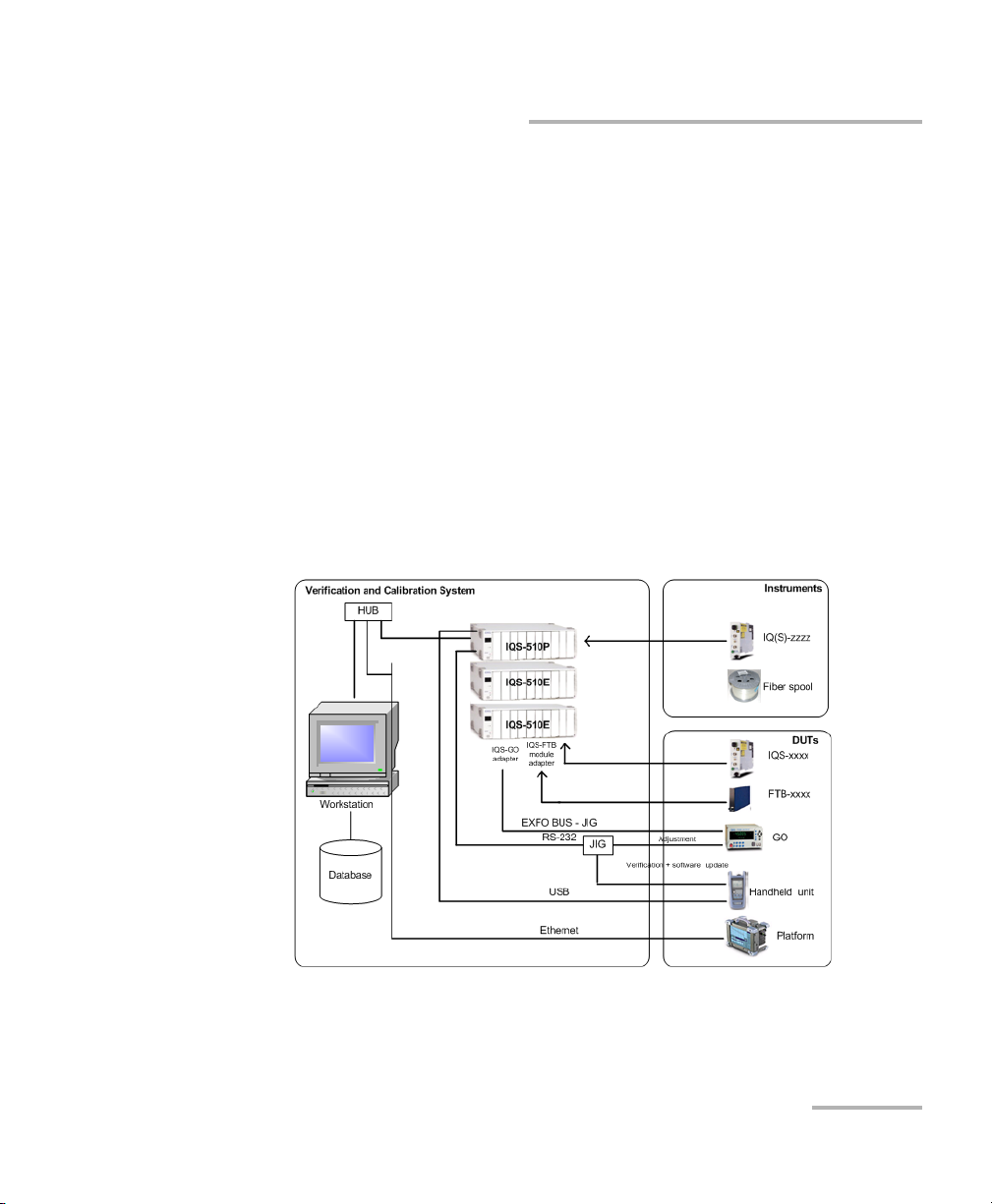
The system includes:
³ a computer, on which the application and database are located
³ an IQS-500 controller unit that contains the instruments requiring a
warmup period
³ one or several IQS-500 expansion units that could contain both
instruments that do not require a warmup period and DUTs.
Both instruments and DUTs can be inserted in the same IQS-500
expansion unit (in specific areas, refer to Configuring Areas Specific for
Instruments on page 19). You may find useful to insert only instruments
that do not require a warmup period in an expansion unit that also
houses DUTs. This way, turning off the expansion unit to insert your
DUTs, will not affect the instruments warmup.
The required instruments vary according to the DUTs and the type of
verification and adjustment you want to perform.
Calibration System 9
Page 14

Introducing the IQS-12002B Calibration System
Conventions
Conventions
Before using the product described in this manual, you should understand
the following conventions:
WARNING
Indicates a potentially hazardous situation which, if not avoided,
could result in death or serious injury. Do not proceed unless you
understand and meet the required conditions.
CAUTION
Indicates a potentially hazardous situation which, if not avoided,
may result in minor or moderate injury. Do not proceed unless you
understand and meet the required conditions.
CAUTION
Indicates a potentially hazardous situation which, if not avoided,
may result in component damage. Do not proceed unless you
understand and meet the required conditions.
IMPORTANT
Refers to information about this product you should not overlook.
10 IQS-12002B
Page 15
2 Getting Started with Your
Calibration System
Inserting and Removing Test Modules
CAUTION
Never insert or remove a module while the controller unit and its
expansion units are turned on. This will result in immediate and
irreparable damage to both the module and unit.
To insert a module into the controller or expansion unit:
1. Exit IQS Manager and turn off all your units.
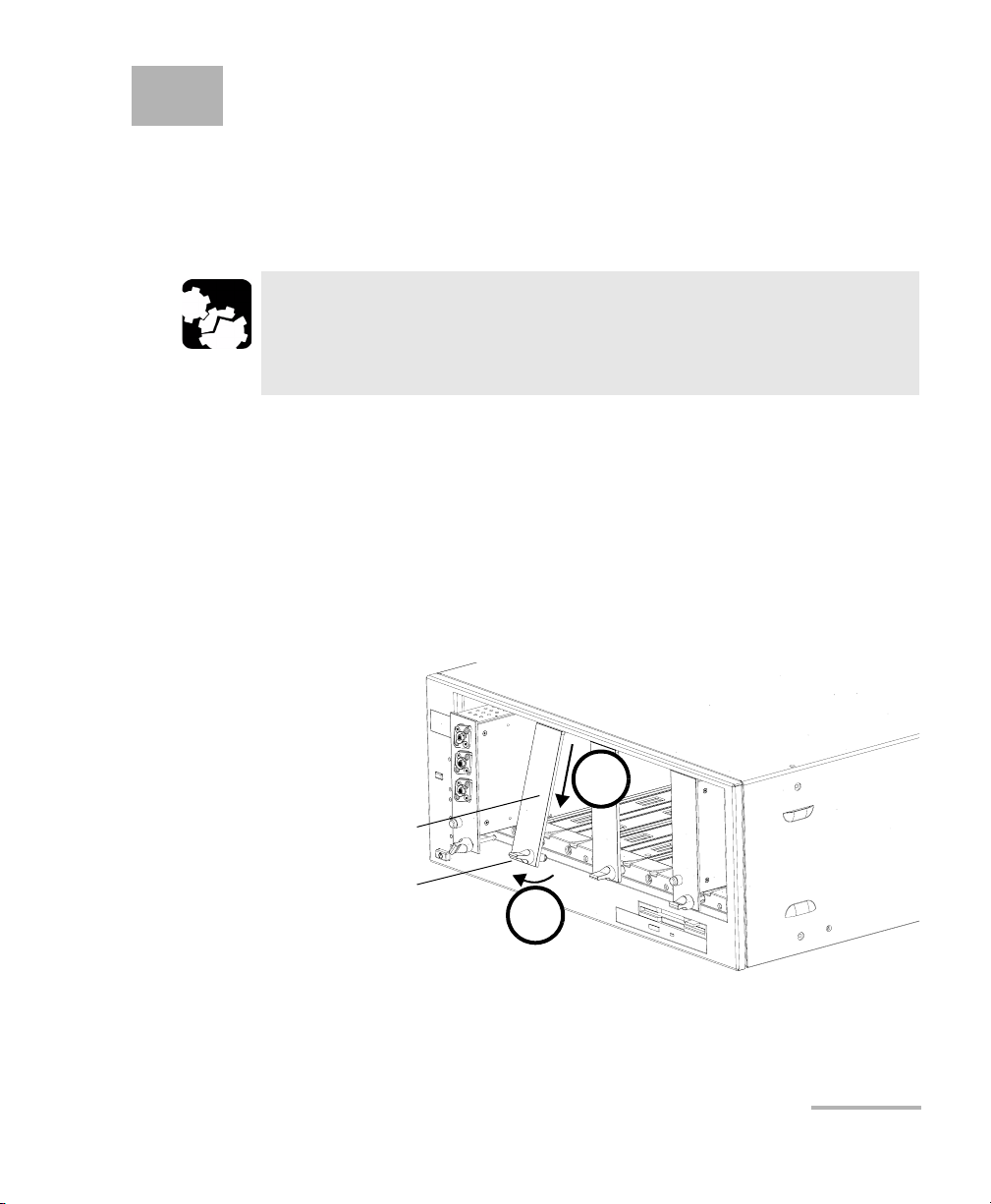
2. Remove the protective cover from the desired unused module slot.
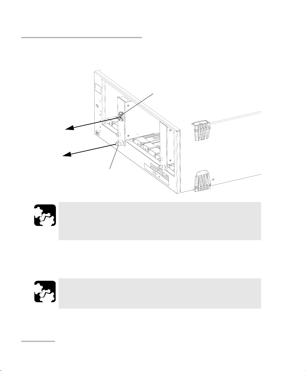
2a. Pull the retaining screw knob firmly towards you and release the
bottom of the cover.
2b. Gently pull the top of the protective cover downwards, to remove
it from the unit grooves.
2b
Protective cover
Retaining screw
knob
2a
3. Position the module so that its front panel is facing you and the top and
bottom protruding edges are to your right.
Calibration System 11
Page 16
Getting Started with Your Calibration System
Inserting and Removing Test Modules
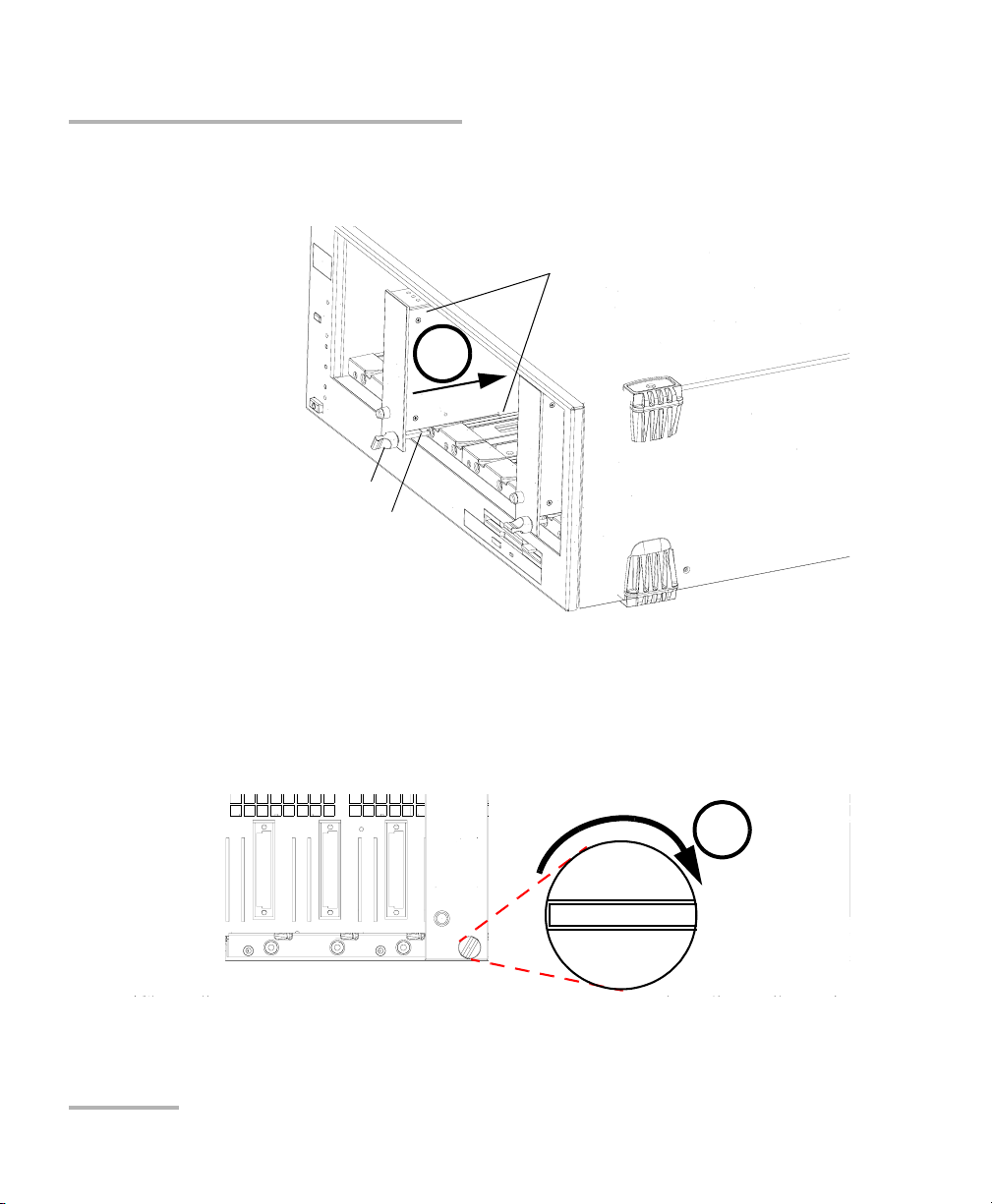
4. Insert the protruding edges of the module into the grooves of the unit’s
module slot.
5
Retaining screw knob
Retaining screw
Protruding edges
(right side of module)
5. Push the module all the way to the back of the slot, until the retaining
screw makes contact with the unit casing.
6. While applying slight pressure to the module, turn the retaining screw
knob (located at the bottom of the panel) clockwise until the knob is
horizontal. This will secure the module into its “seated” position.
6
The module is correctly inserted when its front panel is flush with the front
panel of the controller or expansion unit.
12 IQS-12002B
Page 17
Getting Started with Your Calibration System
Inserting and Removing Test Modules
When you turn on the controller unit, the startup sequence will
automatically detect your module.
Note: You can insert IQ modules into your controller or expansion unit; the IQS
Manager software will recognize them. However, the IQS-500 locking
mechanism (retaining screw) will not work for IQ modules.
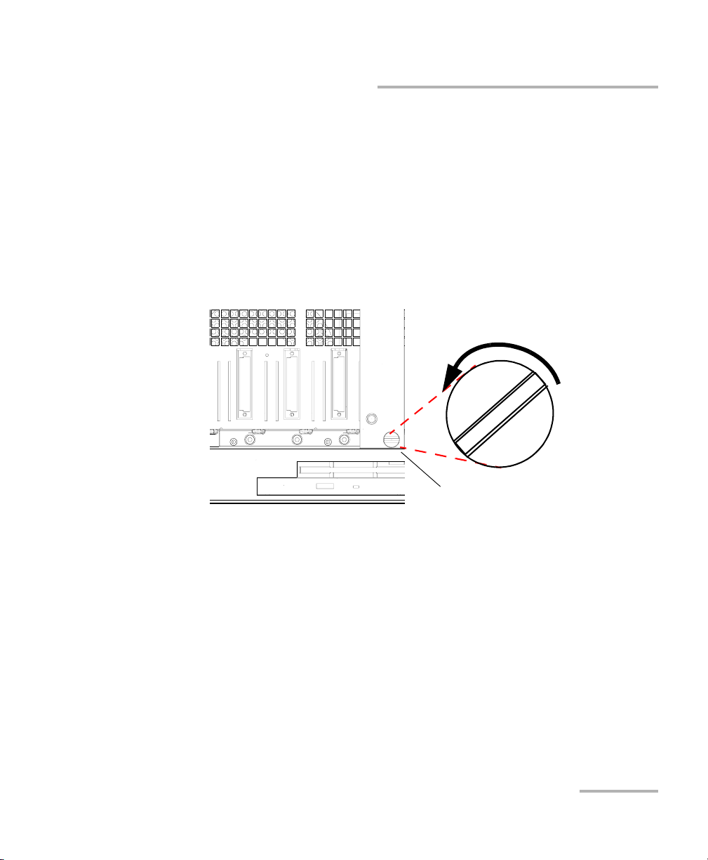
To remove a module from your controller or expansion unit:
1. While pulling gently on the knob, turn it counterclockwise until it stops.
The module will slowly be released from the slot.
Retaining screw knob
Calibration System 13
Page 18
Getting Started with Your Calibration System
Inserting and Removing Test Modules
2. Place your fingers underneath the module or hold it by the retaining
screw knob (NOT by the connector) and pull it out.
Connector
NO
YES
Retaining screw
knob
CAUTION
Pulling out a module by a connector could seriously damage both
the module and connector. Always pull out a module by the
retaining screw knob.
3. Cover empty slots with the supplied protective covers. Simply slide the
top of the protective cover into the upper grooves of the unit, and then
snap into place by pushing the retaining screw knob.
CAUTION
Failure to reinstall protective covers over empty slots will result in
ventilation problems.
14 IQS-12002B
Page 19
Getting Started with Your Calibration System
Installing Hardware Components
Installing Hardware Components
Both instruments and DUTs can be inserted in the same IQS-500 expansion
unit (in specific areas). You may find useful to insert only instruments that
do not require a warmup period in an expansion unit that also houses
DUTs. This way, turning off the expansion unit to insert your DUTs, will not
affect the instruments warmup. For more information on how to define the
area reserved to instruments, see Configuring Areas Specific for
Instruments on page 19.
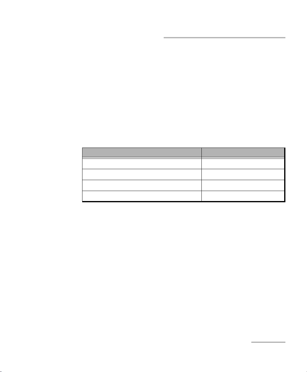
To avoid multiple warmup periods, you can consult the list of required
instruments for the test you want to perform.
Instrument Warmup period
Source 60 minutes
EDFA 60 minutes
Power meter 15 minutes
Others no warmup
The application will show you the required connections, step by step,
during the test.
Calibration System 15
Page 20

Getting Started with Your Calibration System
Starting and Exiting the Calibration System Application
Starting and Exiting the Calibration System
Application
To start the Calibration System application:
1. Turn on the IQS-500 controller and expansion units.
IMPORTANT
Wait until the LED push button of all the modules (except the
polarization or mode scrambler) light up before starting the
application. Otherwise, the application will not be able to link to
the hardware.
2. Turn on the computer on which the application is installed and log on
as “operator” or “manager” and enter the password.
3. From the computer, on the Windows taskbar, click the Start button
and select Programs > EXFO > IQS-12002B.
OR
Double-click the IQS-12002B Calibration System icon.
4. When the application prompts you, log on to the system.
16 IQS-12002B
Page 21
Getting Started with Your Calibration System
Starting and Exiting the Calibration System Application
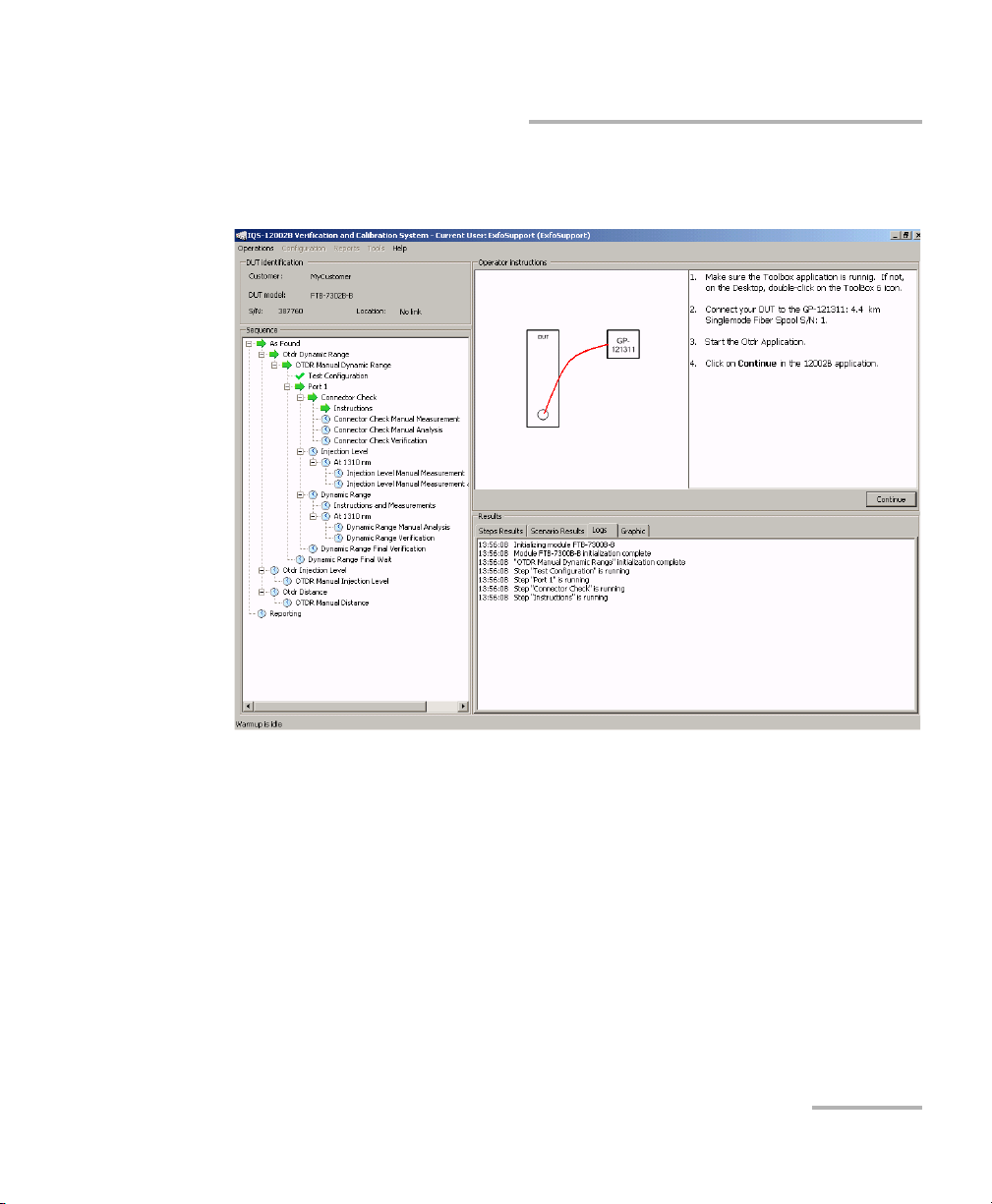
The main window (shown below) contains all the commands required to
control your system.
To exit the Calibration System application:
1. From the File menu, click Exit.
2. Turn off the controller and expansion units.
Calibration System 17
Page 22

Getting Started with Your Calibration System
Reinstalling or Upgrading the IQS-12002B Calibration System Application
Reinstalling or Upgrading the IQS-12002B
Calibration System Application
Please be careful before uninstalling the application. When processed, all
data saved in the database will be lost. This include the DUT results, DUT
creation, standards creation, standard traceability, DUT traceability,
certificates, all users modifications, etc.
Normally you would not have to install the Calibration System application,
except in particular circumstances (such as after having reinstalled
Microsoft Windows).
Please contact the customer’s service to proceed with the
installation/upgrade of the system.
18 IQS-12002B
Page 23
3 Setting Up Your Calibration
System
Configuring Areas Specific for Instruments
Since the system can house instruments and DUTs in the same expansion
unit, you must specify which area is dedicated to the instruments. The
application will then be able to identify which modules must be
considered as instruments and which as DUTs.
To configure the area for instruments:
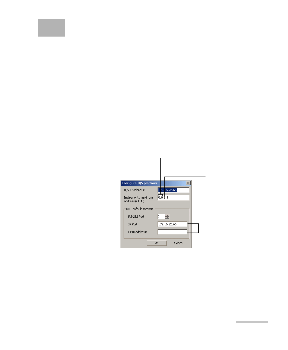
1. From the Too ls menu, select System > Configure IQS Platform.
2. In the Instruments maximum address (CLUS) box, enter the address
of the last slot you want to use for instruments. The application will
assign the next slots to DUTs.
Do not modify the first
two numbers
Unit number
(indicated on front panel of
controller or expansion unit)
Slot number
Increase when DUT is
connected to the unit
Calibration System 19
by RS
-232
3. Click OK to confirm.
Do not modify
Page 24

Setting Up Your Calibration System
Configuring Access Levels and Passwords
Configuring Access Levels and Passwords
To comply with standard ISO 17025, you must be able to identify who
(which user) verified and/or adjusted a particular DUT.
There are three types of users:
³ Operator: verifies and adjusts DUTs, and generates certificates.
³ Manager: has the same rights as the operator and can also configure
the system.
³ Administrator: has the same rights as the manager and can also install
components and complete the initial system configuration.
Each system user must have a password.
Only users with administrator rights can create, modify, and delete user
profiles in the system. A user profile contains a user name, a password, a
permitted access level, etc.
20 IQS-12002B
Page 25
Setting Up Your Calibration System
Configuring Access Levels and Passwords
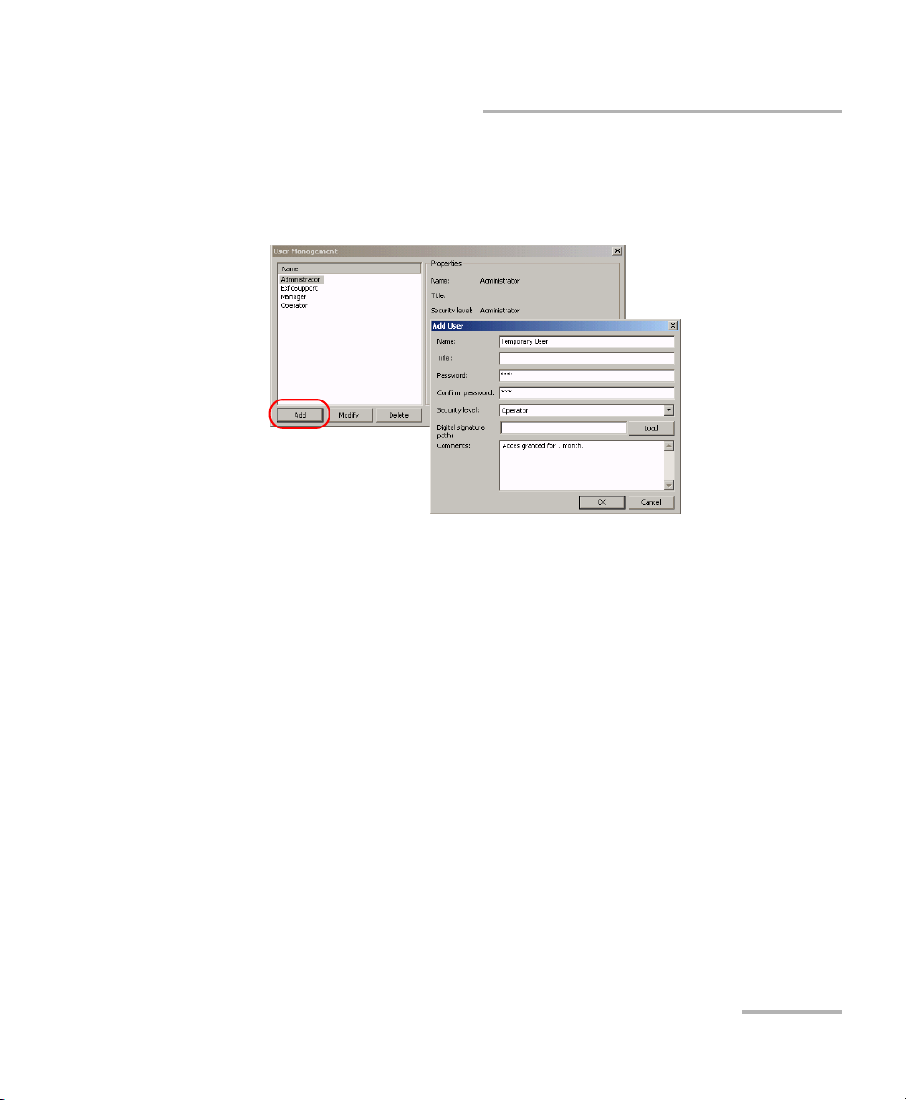
To create a user profile:
1. From the Tools menu, select System > User Management.
2. Click Add to create a user.
3. In the Add User box, fill in the information and click OK to confirm.
Clicking Cancel takes you back to the main window.
To modify a user profile:
1. From the Tools menu, select System > User Management.
2. From the Name list, select the user profile you want to modify.
3. Click Modify.
4. Modify the information and click OK to confirm.
Clicking Cancel takes you back to the main window.
To delete a user profile:
1. From the Tools menu, select System > User Management.
2. From the Name list, select the user profile you want to delete.
3. Click Delete and confirm deletion.
Clicking Cancel takes you back to the main window.
Calibration System 21
Page 26
Setting Up Your Calibration System
Configuring the Due-for-Calibration Reminder
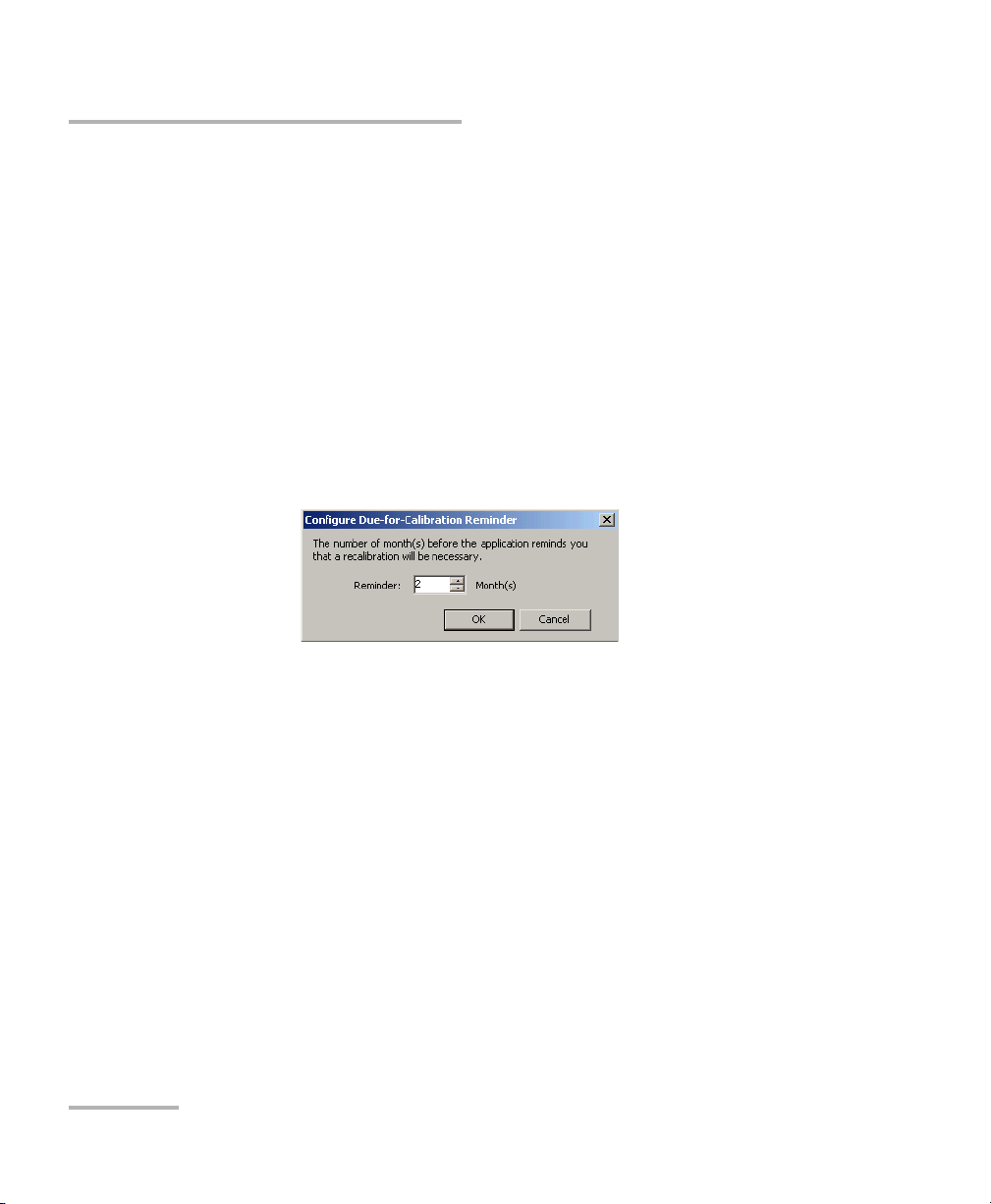
Configuring the Due-for-Calibration Reminder
Since the system relies on the accuracy of standards, the application will
warn you before a standard is due for recalibration (by default, 2 months
ahead). You can set the number of months before the application reminds
you that a recalibration will be necessary. For information on how to
proceed when a standard is back from calibration, see Using a Standard
after Recalibration on page 54.
To configure the due-for-calibration reminder:
1. From the Tools menu, select System > Configure
Due-for-Calibration Reminder.
2. Enter the desired number of months and click OK.
22 IQS-12002B
Page 27
Setting Up Your Calibration System
Activating or Deactivating the Warmup Confirmation
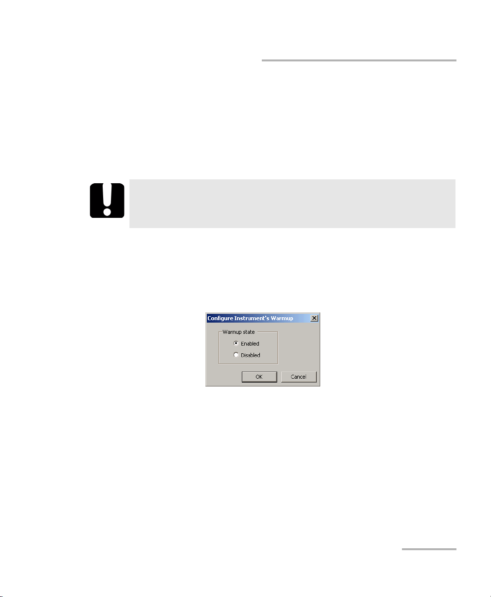
Activating or Deactivating the Warmup
Confirmation
By default, the application prompts you to select the instruments and DUT
for which a warmup is wanted. You can deactivate the warmup
confirmation. It is always possible to perform a warmup manually
afterwards (see Launching a Manual Warmup on page 28).
IMPORTANT
To ensure accurate results, EXFO recommends to always perform
warmup.
To activate or deactivate the automatic warmup confirmation:
1. From the Tools menu, select System > Configure Instrument’s
Warmup.
2. Select the desired option and click OK to confirm.
The application will take the new setting into account the next time you
start the application or turn on the expansion unit.
Calibration System 23
Page 28
Setting Up Your Calibration System
Configuring Main Window Appearance
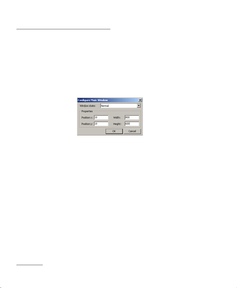
Configuring Main Window Appearance
By default, the main window is maximized. However, you can configure its
size and position.
To configure main window appearance:
1. From the Tools menu, select System > Configure Main Window.
2. From the Window state list, select the desired appearance. If you
select Normal, you can also specify the size and position.
24 IQS-12002B
Page 29
4 Operating Your Calibration
System
Installing the EXFO Universal Interface (EUI)
The EUI fixed baseplate is available for connectors with angled (APC) or
non-angled (UPC) polishing. A green border around the baseplate
indicates that it is for APC-type connectors, as shown below:
Green border
indicates APC
option
To install an EUI connector adapter onto the EUI baseplate:
1. Hold the EUI connector adapter so the dust cap opens downwards.
Bare metal
(or blue border)
indicates UPC
option
3
4
2
2. Close the dust cap in order to hold the connector adapter more firmly.
3. Insert the connector adapter into the baseplate.
4. While pushing firmly, turn the connector adapter clockwise on the
baseplate to lock it in place.
Calibration System 25
Page 30

Operating Your Calibration System
Cleaning and Connecting Optical Fibers
Cleaning and Connecting Optical Fibers
To ensure maximum power and to avoid erroneous readings:
³ Always clean fiber ends as explained below before inserting
them into the port. EXFO is not responsible for damage or
errors caused by bad fiber cleaning or handling.
³ Ensure that your patchcord has appropriate connectors. Joining
mismatched connectors will damage the ferrules.
To connect the fiber-optic cable to the port:
1. Clean the fiber ends as follows:
1a. Gently wipe the fiber end with a lint-free swab dipped in isopropyl
alcohol.
1b. Use compressed air to dry completely.
IMPORTANT
1c. Visually inspect the fiber end to ensure its cleanliness.
2. Carefully align the connector and port to prevent the fiber end from
touching the outside of the port or rubbing against other surfaces. If
your connector features a key, ensure that it is fully fitted into the port’s
corresponding notch.
3. Push the connector in so that the fiber-optic cable is firmly in place,
thus ensuring adequate contact.
If your connector features a screwsleeve, tighten the connector
enough to firmly maintain the fiber in place. Do not overtighten, as this
will damage the fiber and the port.
Note: If your fiber-optic cable is not properly aligned and/or connected, you will
notice heavy loss and reflection.
26 IQS-12002B
Page 31

Operating Your Calibration System
Viewing the Required Instruments
Viewing the Required Instruments
Before launching a test sequence, you can view the instruments that are
required. This way, you will not have to turn off the controller or expansion
units to insert the instruments and wait for the warmup period.
To view the required instruments:
1. From the Configuration menu, click Scenario.
2. Select the desired DUT type and model, and click Search.
3. From the Scenarios box, select a test scenario.
4. Click Calibration Instruments to view the list of instruments required
for the selected scenario.
5. Repeat steps 3 and 4 for every scenario to be included in the sequence.
6. Close the windows to return to the application main window.
Calibration System 27
Page 32

Operating Your Calibration System
Launching a Manual Warmup
Launching a Manual Warmup
By default, the application prompts you at startup to select the instruments
for which a warmup is wanted. If you have deactivated the warmup
confirmation or if you have cancelled the warmup at the application
startup, you can still launch it manually.
To launch a manual warmup:
From the Too ls menu, select System > Start Warmup.
Note: If the War mup window does not appear, the warmup has already been
completed.
Locating IQS Modules
You can access the list of all IQS modules inserted in the system. The list
includes instruments and DUTs, and their position in the system (unit and
slot number). This allows you to retrieve the model and serial number of
the modules without having to turn off the IQS-500 controller or expansion
units.
To locate IQS modules:
From the Too ls menu, select System > Detect IQS Modules.
28 IQS-12002B
Page 33

Operating Your Calibration System
Performing a Test
Performing a Test
The test sequence you have built can be used immediately or saved it for
future use. Once a test is underway, you can stop it and resume it later
from the point it was stopped.
The application will guide you through the necessary steps from DUT
creation to printing results. You can generate reports that are ISO/IEC 17025
compliant. They can take into account measurement uncertainties or not
(i.e. pass or fail status without considering uncertainties). You can also
export results to a PDF file.
Note: It is also possible to perform several tasks, such as adding a new DUT or a
new customer, directly from the application menus.
Note: When creating a new sequence, the system verifies that all necessary
connected standards are present in the platform. If there are more
connected standards of a particular kind than needed, the system reserves
them in the detection order (unit 1 and slot 1, unit 1 and slot 2, and so on).
If you would like to use other connected standards than the reserved ones,
you must remove the undesired standards from the platform.
WARNING
Do not install or terminate fibers while a light source is active.
Never look directly into a live fiber and ensure that your eyes are
protected at all times.
WARNING
Use of controls, adjustments and procedures for operation and
maintenance other than those specified herein may result in
hazardous radiation exposure.
Calibration System 29
Page 34

Operating Your Calibration System
Per formin g a Tes t
To launch a test sequence:
1. From the Operations menu, click Create Sequence.
2. Select Search an existing DUT and enter the DUT serial number.
If the DUT already exists in the database, the application will retrieve it.
If it does not exist, the application will create it.
If necessary, confirm the creation of the DUT.
Note: If you click Next without entering a serial number, the application displays
the list of created DUTs.
30 IQS-12002B
Page 35

Operating Your Calibration System
Performing a Test
3. Enter the information in the appropriate boxes. Mandatory information
is indicated by a “*”.
To visualize DUTs and
their serial numbers
To create a customer in
the database
4. Click OK to confirm.
5. The application displays DUT information; click Next.
6. Prepare your DUT as shown on screen and click Next.
Calibration System 31
Page 36

Operating Your Calibration System
Per formin g a Tes t
7. Under Wo r k type, select the operation you want to perform. The
available choices depend on the type of device you are testing and on
available instruments.
To indicate if the
test is performed
by your company
or on behalf of
EXFO.
8. Under Additional info, enter the information that will appear in the
report.
9. Click Next.
10. In the Fiber selection box, specify the fiber connector, the fiber
adapter, and the fiber type you are using.
To a d d t h e s e le c te d
comments to your
report.
11. Click Next
32 IQS-12002B
Page 37

Operating Your Calibration System
Performing a Test
12. From the Measurement and Adjustment Procedure Selection box,
select the scenarios you want to include in your test sequence.
Note: Some scenarios cannot be cleared from the list. These are mandatory
scenarios and must be performed for the selected DUT.
13. To create custom specifications for a scenario, proceed as follows:
13a.Select the scenario you want to customize and click Create.
13b.From the Based on list, select a set of specifications to be used as
a template.
13c. Click Customize to create the new set of specifications and
values.
13d.Click OK.
Calibration System 33
Page 38

Operating Your Calibration System
Per formin g a Tes t
14. Back in the Measurement and Adjustment Procedure Selection box,
make sure Custom Specifications appears in the Specification
revision list.
15. Click Next and click Complete to close the wizard.
The application will prompt you to confirm if you want to perform the
acquisition now or later.
16. If the required standards have not been added to the database yet, the
application will prompt you to add them; proceed as follows:
16a.Click OK.
16b.Enter the required information and click OK.
16c. Confirm the authority name and calibration date.
16d.Click and link the calibration certificate file provided by the
calibration authority.
16e.Click OK.
34 IQS-12002B
Page 39

Operating Your Calibration System
Performing a Test
17. When the application prompts you, select the instruments that must
have a warmup period and click OK.
18. Follow the instructions appearing on screen.
At the end of a scenario, the application displays the results.
Note: Before printing the report, you can still modify the information it contains,
but you cannot modify the measures.
Calibration System 35
Page 40

Operating Your Calibration System
Per formin g a Tes t
19. The application displays a preview of the report. It will also be possible
to print or export results afterwards (see Printing or Exporting Results
on page 37).
Note: To let the application consider the test sequence completed, you must
perform a print or export of the report. As long as this is not done, the
sequence will remains in the Open Sequence dialog windows and the
results will not be accessible in the DUT history or traceability reports.
To change the default
location of the .pdf file
When you have finished, click Close.
To launch an existing test sequence:
1. From the Operations menu, click Open Sequence.
2. Follow the instructions appearing on screen.
To resume a test sequence:
From the Operations menu, click Run Sequence.
The application will resume the test from where it stopped.
36 IQS-12002B
Page 41

Operating Your Calibration System
Printing or Exporting Results
Printing or Exporting Results
You can print or export results of the DUTs for previous test sequences.
To print or export results:
1. From the Configuration menu, select DUT > Search.
2. Enter criteria to retrieve the DUT information and click Search.
IMPORTANT
If you leave the Serial number box empty, the system will retrieve
all DUTs matching the information entered in the other boxes and
lists.
3. Click History.
Calibration System 37
Page 42

Operating Your Calibration System
Printing or Exporting Results
4. From the DUT History box, select the row indicating that the report
has been printed and click Certificate.
Note: Upon clicking Certificate, the systems offers you the possibility to make
modifications before printing the report. If you choose to do so, a box opens
to let you make the changes and a note is automatically added in the “As
found” and “As left” fields of the report.
5. In the View Report box, click Print, or click Export to save the report
in the PDF format.
6. Click Close.
38 IQS-12002B
Page 43

Operating Your Calibration System
Printing Reports
Printing Reports
You can view or print traceability results of the DUTs or Standards you have
tested or used in previous test sequences.
To view or print Forward Traceability results:
1. From the Report menu, click Forward Traceability.
2. In the Serial number box, type the DUT serial number (leave the box
empty to get all tested DUTs) and click Search.
3. Select the desired DUT in the list.
4. Click History.
Calibration System 39
Page 44

Operating Your Calibration System
Printing Reports
5. From the DUT History box, select the event for which you want to
view the traceability information.
Note: The information depends on the date of the selected event. On the Forward
Traceability Report, the information starts with the date the DUT was
added and ends with the date of the selected event. To see all the
information, you must select the event with the most recent date.
6. When the event is selected, click Forward Traceability to see the
results.
To view or print Reverse Traceability results:
1. From the Report menu, click Reverse Traceability.
2. In the Serial number box, type the Standard serial number (leave the
box empty to get all Standards) and click Search.
40 IQS-12002B
Page 45

Operating Your Calibration System
Printing Reports
3. Select the desired Standard in the list.
4. Click History.
5. From the Standard History box, select the event for which you want
to view the traceability information.
Note: The information depends on the date of the selected event. On the Reverse
Traceability Report, the information starts with the date of the last
calibration and ends with the current date. To see all the information, you
must select the event with the most recent date.To see all the information,
you must select the date the Standard was first calibrated.
6. Click Reverse Traceability to see the results.
Calibration System 41
Page 46

Page 47

5 Troubleshooting
This chapter presents a list of common problems and their solution, the
technical support offered on the web and at EXFO facilities, and product
shipping information.
Solving Common Problems
Problem Possible cause Solution
Communication loss
between PC and IQS
system
Instruments do not
warm up properly
Error message
“Warm-up has
encountered an
error.”
Getting a French
message while
calibrating the
FTB-100B power
meter.
You have logged
yourself out.
The computer has
gone into the stand-by
mode.
Logging out closes the communication
port. Make sure that all operations of the
IQS system are completed before you
log out.
Change the stand-by mode settings as
follows: on the computer desktop,
make a right-click and, on the
contextual menu, click Properties. On
the Screen Saver tab, click Power and,
under Settings for Home/Office Desk
power scheme, select Never in the
three lists.
Try installing all your instruments
(sources and calibration power meter)
in the controller unit instead of the
expansion units.
Restart the warm-up period as follows:
From the To ols menu, select System >
Start Warmup.
If the instruments still do not warm-up
properly, restart the system.
It means that the serial link is available
for calibration.
Calibration System 43
Page 48

Troubleshooting
Finding Information on the EXFO Web Site
Problem Possible cause Solution
Error message
“Catastrophic failure”
Calibration has a Fail
in Distance result.
Interruption of the
dead zone calibration
Impossible to print
information on a
specific DUT.
Finding Information on the EXFO Web Site
The EXFO Web site provides answers to frequently asked questions (FAQs)
regarding the use of your IQS-12002B Calibration System.
Incorrect connections
for the FOT-10A or
FOT-10A unit.
The automatic
positioning of events
for an FTB-7000B-B
OTDR is incorrect.
The automatic
positioning of the
events is incorrect.
This DUT has never
been tested.
Disconnect the unit, close all
applications, and restart the system.
Make sure the connection procedure is
properly done.
Positioning must be done manually. Set
marker A right before the reflective
event at 50 m and marker B right before
the end of fiber event.
Make sure that the standard distance
information include the 3-m patchcord
as described in Configuring the
FTB-7000D OTDR on the IQS-12002B on
page 79.
Test the DUT and try again.
To access FAQs:
1. Ty pe http://www.exfo.com in your Internet browser.
2. Click on the Support tab.
3. Click on FAQs and follow the on-screen instructions. You will be given
a list of questions pertaining to your subject.
The EXFO Web site also provides the product’s most recent technical
specifications.
44 IQS-12002B
Page 49

Troubleshooting
Contacting the Technical Support Group
Contacting the Technical Support Group
To obtain after-sales service or technical support for this product, contact
EXFO at one of the following numbers. The Technical Support Group is
available to take your calls from Monday to Friday, 7:30 a.m. to 8:00 p.m.
(Eastern Time in North America).
Technical Support Group
400 Godin Avenue
Quebec (Quebec) G1M 2K2
CANADA
To accelerate the process, please have information such as the name and
the serial number (see the product identification label—an example is
shown below), as well as a description of your problem, close at hand.
1 866 683-0155 (USA and Canada)
Tel.: 1 418 683-5498
Fax: 1 418 683-9224
support@exfo.com
P/N
**************** A
S/N
542392-3D
Made in Canada QST442B
January 2020
Ver.
Mfg.
date
465 Godin Avenue
Vanier (Quebec) G1M 3G7 CANADA
IQS-12002B
Calibration System 45
Page 50

Troubleshooting
Transportation
Transportation
Maintain a temperature range within specifications when transporting the
unit. Transportation damage can occur from improper handling. The
following steps are recommended to minimize the possibility of damage:
³ Pack the unit in its original packing material when shipping.
³ Avoid high humidity or large temperature fluctuations.
³ Keep the unit out of direct sunlight.
³ Avoid unnecessary shock and vibration.
46 IQS-12002B
Page 51

6 Maintenance
To help ensure long, trouble-free operation:
³ Always clean fiber-optic connectors before using them.
³ Keep the unit free of dust.
³ Clean the unit casing and front panel with a cloth slightly dampened
with water.
³ Store unit at room temperature in a clean and dry area. Keep the unit
out of direct sunlight.
³ Avoid high humidity or significant temperature fluctuations.
³ Avoid unnecessary shocks and vibrations.
³ If any liquids are spilled on or into the unit, turn off the power
immediately and let the unit dry completely.
Use of controls, adjustments and procedures for operation and
maintenance other than those specified herein may result in
hazardous radiation exposure.
WARNING
Calibration System 47
Page 52

Maintenance
Cleaning EUI Connectors
Cleaning EUI Connectors
Regular cleaning of EUI connectors will help maintain optimum
performance. There is no need to disassemble the unit.
If any damage occurs to internal connectors, the module casing will
have to be opened and a new calibration will be required.
To clean EUI connectors:
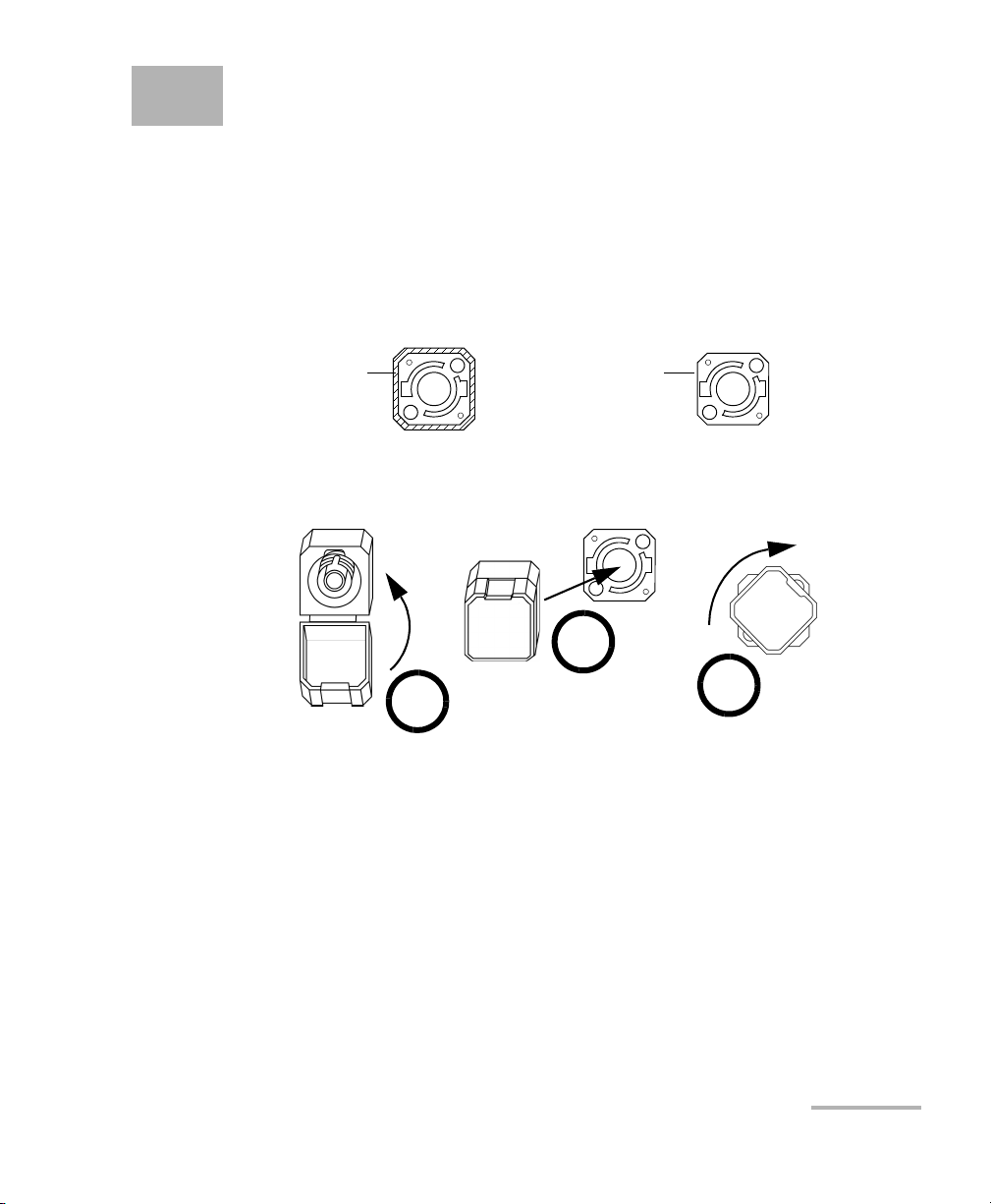
1. Remove the EUI from the instrument to expose the connector
baseplate and ferrule.
IMPORTANT
Turn
Push
2. Moisten a 2.5 mm cleaning tip with one drop of isopropyl alcohol
(alcohol may leave traces if used abundantly).
3. Slowly insert the cleaning tip into the EUI adapter until it comes out on
the other side (a slow clockwise rotating movement may help).
Pull
3
4
5
48 IQS-12002B
Page 53

Cleaning EUI Connectors
4. Gently turn the cleaning tip one full turn, then continue to turn as you
withdraw it.
5. Repeat steps 3 to 4 with a dry cleaning tip.
Note: Make sure you don’t touch the soft end of the cleaning tip.
6. Clean the ferrule in the connector port as follows:
6a. Deposit one drop of isopropyl alcohol on a lint-free wiping cloth.
IMPORTANT
Isopropyl alcohol may leave residues if used abundantly or left to
evaporate (about 10 seconds).
Avoid contact between the tip of the bottle and the wiping cloth,
and dry the surface quickly.
6b. Gently wipe the connector and ferrule.
6c. With a dry lint-free wiping cloth, gently wipe the same surfaces to
ensure that the connector and ferrule are perfectly dry.
Maintenance
6d. Verify connector surface with a portable fiber-optic microscope
(e.g., EXFO’s FOMS) or fiber inspection probe (e.g., EXFO’s FIP).
WARNING
Verifying the surface of the connector WHILE THE UNIT IS ACTIVE
WILL result in permanent eye damage.
7. Put the EUI back onto the instrument (push and turn clockwise).
8. Throw out cleaning tips and wiping cloths after one use.
Calibration System 49
Page 54

Maintenance
Cleaning Fixed Connectors
Cleaning Fixed Connectors
Regular cleaning of connectors will help maintain optimum performance.
Do not try to disassemble the unit. Doing so would break the connector.
To clean fixed connectors:
1. Fold a lint-free wiping cloth in four to form a square.
2. Moisten the center of the lint-free wiping cloth with only one drop of
isopropyl alcohol.
Alcohol may leave traces if used abundantly. Avoid contact between
the tip of the bottle and the wiping cloth, and do not use bottles
that distribute too much alcohol at a time.
3. Gently wipe the connector threads three times with the folded and
moistened section of the wiping cloth.
IMPORTANT
IMPORTANT
Isopropyl alcohol takes approximately ten seconds to evaporate.
Since isopropyl alcohol is not absolutely pure, evaporation will
leave microscopic residue. Make sure you dry the surfaces before
evaporation occurs.
4. With a dry lint-free wiping cloth, gently wipe the same surfaces three
times with a rotating movement.
5. Throw out the wiping cloths after one use.
6. Moisten a cleaning tip (2.5 mm tip) with only one drop of isopropyl
alcohol.
50 IQS-12002B
Page 55

Maintenance
Cleaning Fixed Connectors
IMPORTANT
Alcohol may leave traces if used abundantly. Avoid contact between
the tip of the bottle and the cleaning tip, and do not use bottles
that distribute too much alcohol at a time.
7. Slowly insert the cleaning tip into the connector until it reaches the
ferrule inside (a slow clockwise rotating movement may help).
7
8
9
8. Gently turn the cleaning tip one full turn.
9. Continue to turn as you withdraw the cleaning tip.
10. Repeat steps 7 to 9, but this time with a dry cleaning tip (2.5 mm tip
provided by EXFO).
Note: Make sure you don’t touch the soft end of the cleaning tip and verify the
cleanliness of the cotton tip.
11. Throw out the cleaning tips after one use.
Calibration System 51
Page 56

Maintenance
Cleaning Detector Ports
Cleaning Detector Ports
Regular cleaning of detectors will help maintain measurement accuracy.
Always cover detectors with protective caps when unit is not in use.
To clean detector ports:
1. Remove the protective cap and adapter (FOA) from the detector.
2. If the detector is dusty, blow dry with compressed air.
3. Being careful not to touch the soft end of the swab, moisten a cleaning
tip with only one drop of isopropyl alcohol.
Alcohol may leave traces if used abundantly. Do not use bottles that
distribute too much alcohol at a time.
IMPORTANT
IMPORTANT
4. While applying light pressure (to avoid breaking the detector window),
gently rotate the cleaning tip on the detector window.
5. Repeat step 4 with a dry cleaning tip or blow dry with compressed air.
6. Discard the cleaning tips after one use.
52 IQS-12002B
Page 57

Maintenance
Cleaning the FOA Connector Adapter
Cleaning the FOA Connector Adapter
Make sure that the FOA connector adapter is properly cleaned to assure its
accuracy during calibration.
To clean your FOA connector adapter:
1. Remove the FOA from the instrument.
2. Slowly insert and gently rotate a cleaning tip that has been dipped in
isopropyl alcohol into the FOA.
3. Insert a dry cleaning tip to dry.
4. Blow away any remaining lint with clean compressed air.
5. Use a metal wire (diameter smaller than 150 μm) and carefully insert it
through the sleeve until it comes the other way through the pin-hole
(200 μm).
6. Gently rotate the FOA around the wire to ensure that no particle
remains.
7. Finally, whenever the proper instrumentation is available, a visual
camera with enough magnification might allow to inspect the
cleanliness of the FOA pin-hole.
Calibration System 53
Page 58

Maintenance
Using a Standard after Recalibration
Using a Standard after Recalibration
When a standard is back from recalibration, you must add its calibration
information and certificate to the application’s database. Otherwise, you
will not be able to use the module.
To use a standard after recalibration:
1. From the Configuration menu, click Calibration Instruments>
Standards.
2. Select the appropriate standard from the list.
3. Click History.
54 IQS-12002B
Page 59

Maintenance
Using a Standard after Recalibration
4. Click Add Calibration Event.
5. The authority name and calibration date are automatically set.
Click and add the calibration certificate file.
6. When you have finished, click OK. Close all windows to return to the
main window.
The newly calibrated standard is now available.
Calibration System 55
Page 60

Page 61

A Calibration Methods
This chapter presents the methods, on which are based the procedures of
the IQS-12002B Calibration System., for the calibration of power meters
and OTDRs.
Power Meter
The calibration of a power meter includes the calibration of its absolute
power and, for a high-end unit (e.g., IQS power meter), the calibration of
its linearity.
Absolute Power Calibration
Power meter calibration is performed by comparing it with an
IQS-1502 Calibration Power Meter (working standard). Comparison
between the two is done by measuring the output power of a laser source,
such as the IQS-2400 (usually a DFB laser), having excellent wavelength
and power stability.
In order to improve accuracy, the system can integrate a polarization
scrambler, which reduces the uncertainty due to the polarization
dependant response (PDR) of photo detectors.
For calibration at the 850-nm wavelength, the IQS-2400 uses a stabilized FP
laser with the mandatory mode scrambler in order to obtain a stable laser
source.
Calibration System 57
Page 62

Calibration Methods
Pow er Me ter
At all wavelengths, the output power of the laser sources is measured
several times alternating between the calibration power meter and the
power meter under test (DUT). A minimum of five responsivity constants
are calculated for the DUT and are statistically analyzed to ensure that they
are within appropriate limits (e.g. the calculated values must all be inside a
certain range of values). Whenever one or more responsivity constants are
outside the acceptable range, the measured values are considered invalid
and the measurements have to be redone.
The number of measurements taken with the calibration power meter and
the DUT, and the number of comparisons between the two units are set so
as to reduce uncertainties of Type A. These uncertainties include
connection uncertainty and interference due to reflections.
The system uses expanded uncertainty (U) values that are included in the
report. The following tables present the method used to establish the
uncertainty for calibration made at four wavelengths.
58 IQS-12002B
Page 63

Calibration Methods
Power Meter
Calibration System 59
Page 64

Calibration Methods
u(xi
Pow er Me ter
Power meter calibration at 1310 nm and 1550 nm @ 23 °C ± 1 °C
influence uncertainty Unit probability
iXi
1 Factors related to the reference standard rectangular 1.73205 0.000 1 0.000
2 Incertitude d'étalonnage 2.00 % normal 2 1.000 1 1.000
3 Ref non-linearity 0.25 % rectangular 1.73205 0.144 1 0.144
4 Ageing 0.00 % rectangular 1.73205 0.000 1 0.000
5 Ref temperature dependance 1.00 %/°C rectangular 1.73205 0.577 0.01 °C (variation) 0.006
6 Ref PDR (½ (max-min)) 0.64 % rectangular 1.73205 0.370 0.1 ratio applicabilit y 0.037
7 Ref Dependance on spectral bandwith 0.00 % rectangular 1.73205 0.000 1 0.000
8 1/2 Ref's Resolution 0.01 % rectangular 1.73205 0.006 1 0.006
9 Factors related to the DUT rectangular 1.73205 0.000 1 0.000
10 DUT tem perature dependance 1.00 %/°C rectangular 1.73205 0.577 1 °C (variation) 0.577
11 DUT's Dependanc e on spectral bandwith 0.00 % rectangular 1.73205 0.000 1 0.000
12 DUT's PDR (½ (max-min)) 0.35 % rectangular 1.73205 0. 202 0.1 ratio applicability 0.020
13 1/2 DUT's Resolution 0.120 % rectangular 1.73205 0. 069 1 0.069
14 rectangular 1.73205 0.000 1 0.000
15 rectangular 1.73205 0.000 1 0.000
16 Combined effects rectangular 1.73205 0.000 1 0.000
17 Wavelength dependance DUT versus reference std 1.000 %/nm rectangular 1. 73205 0.577 0.5 nm 0.289
18 Source s tability 0.12 % rectangular 1.73205 0. 069 1 0.069
19 rectangular 1.73205 0.000 1 0.000
20 rectangular 1.73205 0.000 1 0.000
21 U-shaped 1.41421 0.000 1 0.000
22 rectangular 1.73205 0.000 1 0.000
23 rectangular 1.73205 0.000 1 0.000
24 TYPE A UNCERTAINTY (includes i nterferance and FOA) 1.50 % 3 measures 1.73205 0.866 1 0.866
y 1.483
Note 1: If there is a polarisation scrambler, the Detector's PDR can be neglected S= 5.0
distribution
divisor standard
uncertainty
expanded uncertainty
sensitivity
coefficient
)
coverage f actor
Unit uncertainty
ci
k= 2
U= 3.0
Limit 1= 2.6
Limit 3= 7.4
contribution
ui(y)(dB)
60 IQS-12002B
Page 65

Calibration Methods
u(xi
Power Meter
influence uncertainty Unit probability
iXi
1 Factors related to the reference standard rectangular 1.73205 0.000 1 0.000
2 Incertitude d'étalonnage 3.00 % normal 2 1.500 1 1.500
3 Ref non-linearity 0.25 % rectangular 1.73205 0.144 1 0.144
4 Ageing 0.00 % rectangular 1.73205 0.000 1 0.000
5 Ref temperature dependance 1.00 %/°C rectangular 1.73205 0.577 0.01 °C (variation) 0.006
6 Ref PDR (½ (max-min)) 0.90 % rectangular 1.73205 0.520 0.1 0.052
7 Ref Dependance on spectral bandwith 0.00 % rectangular 1.73205 0.000 1 rat io applicabil ity 0.000
8 1/2 Ref's Resolution 0.01 % rectangular 1.73205 0.006 1 0.006
9 Factors related to the DUT rectangular 1.73205 0.000 1 0.000
10 DUT tem perature dependance 1.00 %/°C rectangular 1.73205 0.577 1 °C (variation) 0.577
11 DUT's Dependanc e on spectral bandwith 0.00 % rectangular 1.73205 0.000 1 0.000
12 DUT's PDR (½ (max-min)) 0.90 % rectangular 1.73205 0.520 0.1 ratio applicability 0.052
13 1/2 DUT's Resolution 0.120 % rectangular 1.73205 0.069 1 0.069
14 rectangular 1.73205 0.000 1 0.000
15 rectangular 1.73205 0.000 1 0.000
16 Combined effects rectangular 1.73205 0.000 1 0.000
17 Wavelength dependance DUT versus reference std -1.250 %/nm rectangular 1. 73205 -0.722 0.5 nm -0.361
18 Source s tability 0.12 % rectangular 1.73205 0. 069 1 0.069
19 rectangular 1.73205 0.000 1 0.000
20 rectangular 1.73205 0.000 1 0.000
21 U-shaped 1.41421 0.000 1 0.000
22 rectangular 1.73205 0.000 1 0.000
23 rectangular 1.73205 0.000 1 0.000
24 TYPE A UNCERTAINTY (includes i nterferance and FOA) 1.50 % 3 measures 1.73205 0.866 1 0.866
y 1.871
Note 1: If there is a polarisation scrambler, the Detector's PDR can be neglected S= 5.0
Power meter calibration at 1625 nm @ 23 °C ± 1 °C
distribution
divisor standard
uncertainty
expanded uncertainty
)
sensitivity
coefficient
ci
coverage f actor
Unit uncertainty
contribution
ui(y)(dB)
k= 2
U= 3.7
Limit 1= 1.9
Limit 3= 8.1
Calibration System 61
Page 66

Calibration Methods
ℜ
Pow er Me ter
Linearity Calibration
The nonlinearity of the power meter should be calibrated to ensure
accurate measurements at power levels different from the calibration level
and for relative measurements such as loss and gain measurements.
Nonlinearity is the relative difference between the response at a given
power (P) and the reference power (P
The calibration should be made by increasing and decreasing the power
level to detect nonlinearities over each amplifier range and, whenever
possible, at both sides of each amplifier boundary in order to include
nonlinearities at the switching between scales. Detector nonlinearity is
dependent on the wavelength. For example, an InGaAs detector linear at
1310 nm and 1550 nm may be nonlinear at 850 nm.
The method privileged by the international standard on power meter
calibration (IEC 61315 Ed. 2.0 b:2005) is the superposition method. It is the
most accurate and does not require a reference standard as it is a
self-calibrating (ratio-type) method. It consists in verifying that the sum of
the power read in each branch of a 1 × 2 coupler is equal to the total
power read when measuring the two branches simultaneously. This is
performed over the useful dynamic range of the DUT.
NL
):
0
)(
P
1
=
ℜ
−
)(
P
0
62 IQS-12002B
Page 67

Calibration Methods
Power Meter
However, before performing the linearity calibration, both branch of the
coupler have to be balanced (i.e. have the same output power). Balancing
the linearity setup is the basis of this method. It requires a subscript coupler
to split the power in two and a shutter on both branches in order to block
light or let it through. Power is then recombined using a second coupler
before sending the light to the power meter under test. A variable
attenuator on each path is very useful in order to match the output power
of each branch of the coupler. Finally, the power coming from each
individual branch (P
measured on the photo detector. The deviation of P
and Pb) and also from both branches (P
a
from Pa + Pb is the
total
total
) is
local nonlinearity (NLL).
By using an attenuator between the source and the first splitter, the total
power is attenuated by a factor of 2 (~3 dB) with respect to the previous
step. Adding the local nonlinearities and referencing to the reference
power, we obtain the total linearity error (NLglobal), starting from the
reference power level where the nonlinearity is zero. This process is
repeated throughout the desired range.
The following is the procedure to measure nonlinearity using the
superposition method.
Calibration System 63
Page 68

Calibration Methods
Pow er Me ter
To measure nonlinearity:
1. Set the attenuators in the two paths so that the power measured on the
meter is the same whether the light is coming from branch a or from
branch b.
2. Open both shutters and measure the total power from both branches
simultaneously: P
3. Close the shutter on branch b and measure the power on branch a:
P
.
a,i
4. Close the shutter on branch a, open the shutter on branch b, and
measure the power on branch b: P
5. Add the individual power measurements.
If the sum is not equal to the total power measurement, the DUT
presents nonlinearity.
:
NL
total,i
×=
.
.
b,i
P
itotal,
10i
(dB)log10
PP
+
ib,ia,
6. Using the first attenuator, attenuate the total power by the following
factor to the level of the sum of the individual power measurements
calculated in step 5.
10 2log 3,01 dB≅
7. Repeat steps 2 through 6 to cover the desired range.
64 IQS-12002B
Page 69

Calibration Methods
=
Power Meter
8. At the end, the global nonlinearity is the sum of all the local
nonlinearities expressed in decibels (dB), starting calculations from
the reference power level where the nonlinearity is zero (higher order
terms are negligible).
The equations to use are as follows:
For n < 0
+
1
n
−=
)(
∑
=
i
NLPNL
inglobal
0
For n = 0
0)(
PNL
0global
For n > 0
n
+=
∑
i
=
NLPNL
inglobal
1
)(
where:
n < 0 indicates power levels lower than the reference power.
n > 0 indicates power levels higher than the reference power.
NL
is the local nonlinearity for the step (i = 0 for the step where Pab is
i
the reference power).
The result is a list of global nonlinearities for the whole power range in
steps of 3,01 dB.
The largest nonlinearity relative to the reference power is:
NL
max
max NLglobal()dB()±=
This procedure can be performed with decreasing and/or increasing the
power sent to the DUT.
Calibration System 65
Page 70

Calibration Methods
Pow er Me ter
To cover a bigger area of the power meter range, once the test done by
decreasing the power is completed, shift the first attenuator by 1.5 dB and
then start the test at increasing power levels.
Typical uncertainties of this method include:
³ All possible power fluctuations while measuring P
, Pb, and P
a
total
such
as fluctuations of the source due to drifts.
³ Improper balancing of the output powers of each coupler branch (P
and P
). If balancing is not correctly done, the global linearity cannot
b
be easily inferred).
³ Sensitivity to changing reflections.
³ Instabilities due to interference if the coherence length of the laser is
too large.
³ Polarization sensitivity of the power meter and attenuators (when
applicable).
³ Resolution of the power meter.
³ Difference between the individual powers of each step (P
compared to the total power of the next step (P
total,i+1
and Pb,i)
a,i
) (for calculating
global linearity).
a
66 IQS-12002B
Page 71

Calibration Methods
Power Meter
The errors for each step are cumulative and will add to the errors of the
preceding steps.
The system uses an expanded uncertainty (U) value that is included in the
report. The following table presents the method used to establish the
uncertainty for the linearity calibration.
Calibration System 67
Page 72

Calibration Methods
FTB-7000D and FTB-7000B-B OTDR Modules
FTB-7000D and FTB-7000B-B OTDR Modules
Calibration of the FTB-7000D OTDR includes the event and attenuation
dead zones, dynamic range, injection levels, linearity, front connector
position, and distance. Calibration of the FTB-7000B-B family, includes test
or verification of event and attenuation dead zones, dynamic range,
injection level, and distance.
The verification of the technical specifications such as dead zones,
linearity, and dynamic range are more a validation of the expected
instrument performance. However, for an OTDR to produce accurate
distance measurements, a calibration is required and may include some
adjustments.
For any test or calibration, make sure that the front connector of the OTDR
is clean and does not present scratches. If the connector is damaged, it
must be replaced, and Repair must be selected in the Work type box (refer
to step 7 on page 32) of the IQS-12002B application: no measurements, for
which the results would appear in the “As found” section of the report, will
be performed.
Note: All measurements performed on the FTB-7000B-B are to be manually done
and entered as per the instructions given in the IQS-12002B system.
68 IQS-12002B
Page 73

Calibration Methods
FTB-7000D and FTB-7000B-B OTDR Modules
Dynamic Range Test
The dynamic range is verified using various combinations of pulse duration
and distance range with the averaging time set at 45 s. Only one pulse
duration is included in the calibration report, usually 10 μs for singlemode
and 1 μs for multimode. The dynamic range is the difference (in dB)
between the launch level (backscatter trace extrapolated at distance zero)
and the noise floor. The noise floor has many definitions, but the one
mostly accepted in the fiber-optic industry is when the signal-to-noise ratio
equals 1 (SNR = 1). For EXFO OTDRs, we use custom software that
measures the noise floor on the raw data (before conversion in dB), which
is the only way to properly evaluate the standard deviation at the noise
floor level.
When trying to measure the dynamic range, the main difficulty is to
determine the proper noise floor. In general, alternative noise floor
definitions are used (e.g. peak noise level or 98 % noise level) and are then
converted to SNR = 1. Because the interpretation of noise is difficult and
the correct evaluation of the noise floor, when the raw data is not available,
is hard to make, and also because noise has different definitions, it is not
uncommon to find deviations of up to 2 dB between measurements done
with EXFO’s IQS-12002B software and done manually without raw data.
The software indicator of the injection level at each pulse is also verified
when measuring the dynamic range. The results might indicate that an
adjustment is required for one or more pulses. Note that a failure on an
injection level test does not imply a failure on the dynamic range; these are
separate parameters. Moreover, the injection level being only a visual
indicator, its result is not shown on the calibration certificate.
Note: There is no uncertainty value associated with this measurement.
Calibration System 69
Page 74

Calibration Methods
FTB-7000D and FTB-7000B-B OTDR Modules
Linearity Test
Linearity is verified by looking at variations in loss measurements made
over a same portion of fiber at different levels of attenuation (a variable
optical attenuator (VOA) is included in the IQS-12002B Calibration System).
This is performed at the shortest wavelength present in the unit both each
multimode and singlemode ports. The pulse used for multimode
wavelengths is 1 μs and, for singlemode wavelengths, it is 10 μs. In both
cases, the averaging time is set at 45 s.
Linearity is not tested on FTB-7000B-B OTDR modules.
The setup for linearity measurements of multimode OTDRs (7000D series)
is as follows:
Multimode fiber (1 km) Multimode fiber (4 km)
IMPORTANT
OTDR
IQS-3100B-D
The setup for linearity measurements of singlemode OTDRs (7000D series)
is as follows:
Singlemode fiber (4.4 km) Singlemode fiber (17.6 km)
OTDR
Singlemode fiber (17.6 km)
IQS-3100BW
for the FTB-7400D-NS-431
Note: For the FTB-7400D-NS-431, a second fiber length of 17.6 km is required.
70 IQS-12002B
Page 75

Calibration Methods
FTB-7000D and FTB-7000B-B OTDR Modules
The fiber section chosen for the loss measurement must be as far as
possible from the VOA to reduce errors due to recovery on the OTDR.
Usually, the fiber section is chosen to roughly emulate a 0.5-dB loss.
The initial measurement, performed at the minimum attenuation of the
VOA, is considered as the reference loss (A
). Following measurements
ref
are done at higher attenuation. The OTDR loss measurements (A
meet the linearity criteria where nonlinearity (NL) is calculated this way:
A
otdr
NL
1max −±=
A
ref
The linearity specification must be met for a given attenuation range. This
range depends on the OTDR type, the pulse, and the wavelength. The
attenuation range is limited by noise on the trace or recovery after the VOA.
Note: There is no uncertainty value associated with this measurement.
otdr
) must
Calibration System 71
Page 76

Calibration Methods
FTB-7000D and FTB-7000B-B OTDR Modules
Distance Calibration
An OTDR calculates the length of a fiber section by measuring the time of
flight of a light pulse between its launch point and the detection of a
fraction of its reflection. Using the time of flight, the speed of light, and the
index of refraction of the fiber, one can calculate the length of a fiber link.
Before starting the distance calibration procedure, the position of the front
connector must be verified and adjusted if necessary.
Front Connector Position
To determine the position of the front connector, a section of fiber of a
known length is installed at the output of the OTDR. Its length, usually
around 15 m, is measured using a calibrated measurement ribbon. The
front connector position is determined by using the calibrated length of this
15-m fiber as determined by the OTDR. The position of the front connector
is recorded in the OTDR permanent memory and will be used to correctly
locate any event measured with the OTDR.
Note: This calibration is not performed for an FTB-7000B-B OTDR module.
72 IQS-12002B
Page 77

Calibration Methods
FTB-7000D and FTB-7000B-B OTDR Modules
Distance Calibration Method
Distance is calibrated with the use of a reference fiber that is traceable to a
national metrology institute (e.g. METAS, NPL, NIST, NRC).
The following diagram shows the setup used by EXFO for distance
calibration.
Fiber (3 m)
OTDR
OTDR
Fiber spool (50 m) Singlemode fiber (2300 m)
reference standard
FC UPC/FC UPC
Multimode fiber (100 m)
reference standard
FC UPC/FC UPC FC APC
FC UPC/FC UPC FC APC
For multimode OTDRs, calibration is performed on the same fiber for both
50/125 and 62/125 OTDRs (the difference in dispersion in the fiber has a
negligible impact). A 3-meter test Jumper is connected at the far end of the
reference fiber in order to have a similar reflection at both ends.
For singlemode calibration, since the OTDR could be equipped with an
output APC connector, the setup requires a short fiber spool (about
50 m ±1 m) to be installed before the reference fiber. This is done so that
you can set markers at each end of a known reflection of similar level (as
that given by FC UPC to FC UPC connectors: about 55 dB). This also has the
great advantage of allowing the use of an uncalibrated test jumper to
connect an OTDR, equipped with an APC connector at the output, to the
short fiber spool of 50 m.
Calibration System 73
Page 78

Calibration Methods
(
)
⎣
⎦
FTB-7000D and FTB-7000B-B OTDR Modules
Distance Measurement Specification
Distance specification depends on the location offset, distance scale
deviation, and sampling resolution.
S location offset scale deviation distance sampling resolution+×+()±=
For example, for an OTDR of the FTB-7000D family, the distance
specification is:
S ± 0.75 0.0025 % distance 0,04+×+() m=
Note: For FTB-7000B-B, displayed resolution is 1 m for a distance between
markers greater than 1 km. Therefore, specification is to be evaluated
according to S = ±(1 + 0.0025 % x distance + 1) m.
The OTDR specification for distance depends on the range and pulse
duration used, as they will determine the sampling resolution on the trace.
Also, as the optical path changes with wavelength (because of the fiber
effective index dependence on wavelength) and due to the fact that fiber
calibration is performed using a normalized index of refraction of 1.46, the
optical distance of the reference fiber changes with the OTDR wavelength.
The equation which describes the difference in the optical length due to
the difference between the calibration wavelength and the actual
wavelength of the OTDR is:
δLλLcal
where:
S0 is the zero dispersion slope in ps/(nm
For example, Corning gives as a typical value, for the SMF-28 fiber, an S0
coefficient of 0.086 ps/(nm
0.092 ps/(nm
74 IQS-12002B
S0
⋅λ2λcal
⋅
8
manufacturer.
2
* km), at a λ0 of 1311.5 nm ±10 nm.
2
−λ04λ
2
* km), with a maximum value of
2−
λcal
−
⋅+
2
* km), as given by the fiber
c
2−
⋅:=
N
Page 79

Calibration Methods
FTB-7000D and FTB-7000B-B OTDR Modules
EXFO determines the true central wavelength and distribution for the type
of lasers used in an OTDR family (e.g., FTB-7000D, AXS-100). The reference
distance used in the OTDR calibration takes into account the true central
wavelength of the OTDR family. The following table is an example for an
OTDR of the FTB-7000D family.
Calibration System 75
Page 80

Calibration Methods
FTB-7000D and FTB-7000B-B OTDR Modules
Uncertainties
The uncertainties for distance calibration are as follows:
³ Reference fiber (as per the calibration certificate issued by the national
laboratory where the fiber was calibrated).
³ Environment temperatures.
³ Chromatic dispersion.
³ Wavelength differences: calibration wavelength for the reference fiber
versus OTDR wavelength, and OTDR wavelength uncertainties.
³ OTDR resolution.
Traceability
Distance calibration is performed by comparing the length of a reference
fiber (traceable to a national metrology institute) as measured by the OTDR
under test with the reference fiber length given by the specification.
Reference fibers are calibrated at NPL (National Physical Laboratory in the
UK) or METAS (Swiss Federal Office for Metrology).
EXFO traceability of OTDRs
Working
standard
DUT
Reference fiber calibration is traceable to the national metrology of
Switzerland, named METAS or Swiss Federal Office for Metrology.
76 IQS-12002B
Reference fiber
OTDR
Page 81

Calibration Methods
FTB-7000D and FTB-7000B-B OTDR Modules
Dead Zone Calibration
The dead zone depends on the intensity of the reflectance. Compliance to
the specification must be done for a reflectance of –35 dB in multimode
and –45 dB in singlemode.
Note: There is no uncertainty value associated with this calibration.
Attenuation Dead Zone
The attenuation dead zone is the distance between markers A and B
on the OTDR trace presented below.
Attenuation
dead zone
Marker A is positioned at the rising edge of the reflective event.
Marker B is positioned within the falling edge, 0.5 dB above the
backscatter level.
Calibration System 77
Page 82

Calibration Methods
FTB-7000D and FTB-7000B-B OTDR Modules
Event Dead Zone
The event dead zone is the distance between markers A and B on the
OTDR trace presented below.
Dead zone
Markers are positioned on both side of the peak, 1.5 dB below the
maximum peak value.
78 IQS-12002B
Page 83

B Configuring the FTB-7000D
OTDR on the IQS-12002B
Test equipment is configured at the factory before shipping. The
procedures presented in this document address the case when the
IQS-12002B detects a new instrument or when a particular instrument has
not been configured.
Note: The given instructions are for the singlemode FTB-7000D OTDR; however,
you can use the same procedures for the multimode model (lengths,
tolerances, and uncertainties can differ).
The following table shows the list of calibration instruments and standards
for the singlemode and the multimode OTDRs.
Calibration Instruments and Standards
for Singlemode OTDR
GP-121311: 4.4-km fiber spool GP-121492: 1-km multimode fiber spool
GP-121317: 17.6-km fiber spool GP-121490: 4-km multimode fiber spool
IQS-3100BW Variable Attenuator IQS-3100B-D Variable Attenuator
GP-121723: 50-m launch fiber Useless for multimode calibration
GP-121392: distance reference standard GP-121489: multimode distance reference
GP-121310: singlemode front-connector
position (for UPC connectors)
GP-120963: singlemode dead zone GP-121200: multimode dead zone
GP-121310: singlemode front-connector
position (for APC connectors)
Calibration Instruments and Standards
for Multimode OTDR
standard
GP-121487: multimode front-connector
position (for UPC connectors)
GP-121487: multimode front-connector
position (for APC connectors)
Calibration System 79
Page 84

Configuring the FTB-7000D OTDR on the IQS-12002B
When you create a test sequence for an FTB-7000D, you may receive the
following message:
Click OK to proceed with the creation of a calibration instrument.
80 IQS-12002B
Page 85

Configuring the FTB-7000D OTDR on the IQS-12002B
Creating the GP-121311: 4.4-km Fiber Spool as a Calibration Instrument
Creating the GP-121311: 4.4-km Fiber Spool as
a Calibration Instrument
This section presents the procedure to create the 4.4-km fiber spool as a
calibration instrument.
To create the calibration instrument:
1. From the Add a standard window, enter the relevant information:
1a. Match the calibration instrument appearing in the Calibration
Instrument list to the instrument you intend to create.
The calibration name will be displayed in the Calibration
Instrument list.
1b. Enter the instrument serial number.
Calibration System 81
Page 86

Configuring the FTB-7000D OTDR on the IQS-12002B
Creating the GP-121311: 4.4-km Fiber Spool as a Calibration Instrument
1c. Enter the inventory number and comments if necessary.
Note: When the basic model of the calibration instrument is configured to appear
in the Calibration Certificate produced by the IQS-12002B, the information
that you enter in the Inventory number text box will appear in the
Calibration Certificate in the section entitled Standards used to establish
traceability.
1d. Select No calibration required.
2. Click OK.
82 IQS-12002B
Page 87

Configuring the FTB-7000D OTDR on the IQS-12002B
Creating the GP-121317: 17.6-km Fiber Spool as a Calibration Instrument
Creating the GP-121317: 17.6-km Fiber Spool
as a Calibration Instrument
This section presents the procedure to create the 17.6-km fiber spool as a
calibration instrument.
To create the calibration instrument:
1. From the Add a standard window, enter the relevant information:
1a. Match the calibration instrument appearing in the Calibration
Instrument list to the instrument you intend to create.
The calibration name will be displayed in the Calibration
Instrument list.
1b. Enter the instrument serial number.
1c. Enter the inventory number and comments if necessary.
Note: When the basic model of the calibration instrument is configured to appear
in the Calibration Certificate produced by the IQS-12002B, the information
that you enter in the Inventory number text box will appear in the section
entitled Standards used to establish traceability.
1d. Select No calibration required and click OK.
Calibration System 83
Page 88

Configuring the FTB-7000D OTDR on the IQS-12002B
Creating the IQS-3100BW Variable Attenuator as a Calibration Instrument
Creating the IQS-3100BW Variable Attenuator
as a Calibration Instrument
This section presents the procedure to create the IQS-3100BW Variable
Attenuator as a calibration instrument.
To create the calibration instrument:
1. From the Add a standard window, enter the relevant information:
1a. Match the calibration instrument appearing in the Calibration
Instrument list to the instrument you intend to create.
The calibration name will be displayed in the Calibration
Instrument list.
1b. Enter the instrument serial number.
84 IQS-12002B
Page 89

Configuring the FTB-7000D OTDR on the IQS-12002B
Creating the IQS-3100BW Variable Attenuator as a Calibration Instrument
1c. Enter the inventory number and comments if necessary.
Note: When the basic model of the calibration instrument is configured to appear
in the Calibration Certificate produced by the IQS-12002B, the information
that you enter in the Inventory number text box will appear in the section
entitled Standards used to establish traceability.
1d. Select Calibrated (no recalibration required) and click OK.
2. From the Add a Calibration Event window, enter the date as written
on the instrument calibration certificate, and click OK.
Calibration System 85
Page 90

Configuring the FTB-7000D OTDR on the IQS-12002B
Creating the GP-121723: 50-m Launch Fiber as a Calibration Instrument
Creating the GP-121723: 50-m Launch Fiber as
a Calibration Instrument
This section presents the procedure to create the 50-m launch fiber as a
calibration instrument.
To create the calibration instrument:
1. From the Add a standard window, enter the relevant information:
1a. Match the calibration instrument appearing in the Calibration
Instrument list to the instrument you intend to create.
The calibration name will be displayed in the Calibration
Instrument list.
1b. Enter the instrument serial number.
86 IQS-12002B
Page 91

Configuring the FTB-7000D OTDR on the IQS-12002B
Creating the GP-121723: 50-m Launch Fiber as a Calibration Instrument
1c. Enter the inventory number and comments if necessary.
Note: When the basic model of the calibration instrument is configured to appear
in the Calibration Certificate produced by the IQS-12002B, the information
that you enter in the Inventory number text box will appear in the
Calibration Certificate in the section entitled Standards used to establish
traceability.
1d. Select Calibrated (no recalibration required).
2. Click OK.
3. From the Add a Calibration Event window, enter the manufacturing
date (if the day of manufacturing is not available, enter the first day of
the manufacturing month), and click OK.
Calibration System 87
Page 92

Configuring the FTB-7000D OTDR on the IQS-12002B
Creating the GP-121723: 50-m Launch Fiber as a Calibration Instrument
4. From the View Standard Parameters window, click Edit to enter the
length of the reference standard given on the acceptance test plan for
all requested wavelengths (e.g., 56.1 m).
IMPORTANT
Ensure that the Length Tolerance parameter is set to 5 m.
5. Click Close.
88 IQS-12002B
Page 93

Configuring the FTB-7000D OTDR on the IQS-12002B
Creating the GP-121392: Distance Reference Standard
Creating the GP-121392: Distance Reference
Standard
This section presents the procedure to create a distance reference
standard.
To create the reference standard:
1. From the Add a standard window, enter the relevant information:
1a. Match the calibration instrument appearing in the Calibration
Instrument list to the instrument you intend to create.
The calibration name will be displayed in the Calibration
Instrument list.
1b. Enter the instrument serial number.
1c. Enter the inventory number and comments if necessary.
Note: When the basic model of the calibration instrument is configured to appear
in the Calibration Certificate produced by the IQS-12002B, the information
that you enter in the Inventory number text box will appear in the section
entitled Standards used to establish traceability.
1d. Select Calibrated (no recalibration required).
Calibration System 89
Page 94

Configuring the FTB-7000D OTDR on the IQS-12002B
Creating the GP-121392: Distance Reference Standard
2. Click OK.
3. From the Add a Calibration Event window, enter the date as written
on the instrument calibration certificate, and click OK.
90 IQS-12002B
Page 95

Configuring the FTB-7000D OTDR on the IQS-12002B
Creating the GP-121392: Distance Reference Standard
4. From the View Standard Parameters window, click Edit to enter the
length of the reference standard given on the acceptance test plan for
each wavelength (Optical length at central wavelength (m)) along
with its uncertainty (Uncertainty (m)).
Note: If the IQS-12002B requests information on a wavelength not given in the
acceptance test plan (e.g., 1650 nm), enter “0” for both Length_XXXX and
Uncertainty_XXXX.
IMPORTANT
The Calibration Certificate issued by a national calibration laboratory
is the official traceability document for OTDR calibration. Please
make sure that you keep it in an appropriate location in your files.
5. Click Close.
Calibration System 91
Page 96

Configuring the FTB-7000D OTDR on the IQS-12002B
Creating the GP-121310: Calibration Instrument for Singlemode, Front-Connector Position
Creating the GP-121310: Calibration Instrument for Singlemode, Front-Connector Position (UPC Connectors)
This section presents the procedure to create the calibration instrument for
the singlemode, front-connector position for UPC connectors.
To create the calibration instrument:
1. From the Add a standard window, enter the relevant information:
1a. Match the calibration instrument appearing in the Calibration
Instrument list to the instrument you intend to create.
The calibration name will be displayed in the Calibration
Instrument list.
1b. Enter the instrument serial number followed by “(UPC)”
(e.g., 123456 (UPC)).
92 IQS-12002B
Page 97

Configuring the FTB-7000D OTDR on the IQS-12002B
Creating the GP-121310: Calibration Instrument for Singlemode, Front-Connector Position
1c. Enter the inventory number and comments if necessary.
Note: When the basic model of the calibration instrument is configured to appear
in the Calibration Certificate produced by the IQS-12002B, the information
that you enter in the Inventory number text box will appear in the section
entitled Standards used to establish traceability.
1d. Select Calibrated (no recalibration required).
2. Click OK.
3. From the Add a Calibration Event window, enter the date as written
on the instrument calibration certificate, and click OK.
Calibration System 93
Page 98

Configuring the FTB-7000D OTDR on the IQS-12002B
Creating the GP-121310: Calibration Instrument for Singlemode, Front-Connector Position
4. From the View Standard Parameters window, click Edit to enter the
length given on the acceptance test plan for all requested wavelengths.
IMPORTANT
Do not change the Length_Tolerance parameter.
5. Click Close.
IMPORTANT
Now that you have created a calibration instrument for
UPC connectors, you must manually create a calibration instrument
for APC connectors. For more information, see Creating the
GP-121310: Calibration Instrument for Singlemode,
Front-Connector Position (APC Connectors) on page 98.
94 IQS-12002B
Page 99

Configuring the FTB-7000D OTDR on the IQS-12002B
Creating the GP-120963: Singlemode Dead-Zone Calibration Instrument
Creating the GP-120963: Singlemode
Dead-Zone Calibration Instrument
This section presents the procedure to create the dead-zone calibration
instrument. This calibration instrument is created using the length given on
the acceptance test plan.
To create the calibration instrument:
1. From the Add a standard window, enter the relevant information:
1a. Match the calibration instrument appearing in the Calibration
Instrument list to the instrument you intend to create.
The calibration name will be displayed in the Calibration
Instrument list.
1b. Enter the instrument serial number.
Calibration System 95
Page 100

Configuring the FTB-7000D OTDR on the IQS-12002B
Creating the GP-120963: Singlemode Dead-Zone Calibration Instrument
1c. Enter the inventory number and comments if necessary.
Note: When the basic model of the calibration instrument is configured to appear
in the Calibration Certificate produced by the IQS-12002B, the information
that you enter in the Inventory number text box will appear in the section
entitled Standards used to establish traceability.
1d. Select Calibrated (no recalibration required).
2. Click OK.
3. From the Add a Calibration Event window, enter the date as written
on the instrument calibration certificate, and click OK.
4. Use the length of the reference standard given on the acceptance test
and add 3meters to it (new length = 3 m + given length).
96 IQS-12002B
 Loading...