


Z490 Dark

EVGA Z490 DARK (131-CL-E499)
- 1 -
User Guide
EVGA Z490 DARK
Specs and Initial Installation

EVGA Z490 DARK (131-CL-E499)
- 2 -
Table of Contents
Before You Begin… ................................................................................................. - 4 -
Parts NOT in the Kit ............................................................................................................. - 5 -
Intentions of the Kit .............................................................................................................. - 5 -
Motherboard Specifications .................................................................................................. - 6 -
Unpacking and Parts Descriptions ........................................................................................ - 8 -
EVGA Z490 DARK Motherboard LED reference ............................................................. - 10 -
EVGA Z490 DARK Motherboard Component Legend ..................................................... - 14 -
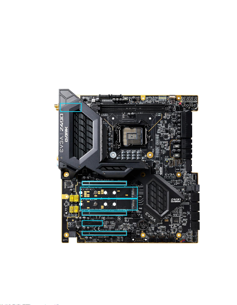
PCIe Slot Breakdown ......................................................................................................... - 27 -
M.2 / U.2 Slot Breakdown .................................................................................................. - 27 -
Preparing the Motherboard ................................................................................................. - 28 -
Installing the CPU .............................................................................................................. - 28 -
Installing the CPU Cooling Device .................................................................................... - 29 -
Installing System Memory .................................................................................................. - 30 -
Installing the I/O Shield ...................................................................................................... - 31 -
Installing the Motherboard...................................................................................... - 31 -
Securing the Motherboard into a System Case ................................................................... - 32 -
Installing M.2 devices ............................................................................................. - 34 -
Installing M.2 Key-M Socket 3 Devices ............................................................................ - 34 -
Tested CPU and Memory ................................................................................................... - 37 -
Tested Memory ................................................................................................................... - 37 -
Tested M.2 Key-M ............................................................................................................. - 38 -
Tested U.2........................................................................................................................... - 39 -
Tested M.2 Key-E............................................................................................................... - 39 -
Connecting Cables .............................................................................................................. - 40 -
Onboard Buttons ................................................................................................................. - 52 -

EVGA Z490 DARK (131-CL-E499)
- 3 -
First Boot ................................................................................................................ - 53 -
M.2 SSD, PCIe SSD, and NVMe SSD Installation steps ................................................... - 55 -
Internal RAID Controller ......................................................................................... - 57 -
Fan Header DC and PWM setup ........................................................................... - 92 -
Setting Up SLI and PhysX...................................................................................... - 96 -
Realtek HD Audio Manager ............................................................................................. - 101 -
EVGA NU Audio ................................................................................................... - 119 -
The NU Audio Control Panel ........................................................................................... - 122 -
NU Audio Custom Settings: ............................................................................................. - 130 -
Installing Drivers and Software ............................................................................ - 141 -
Windows 10 Driver Installation ........................................................................................ - 141 -
Warranty and Overclocking .............................................................................................. - 143 -
Troubleshooting ................................................................................................... - 144 -
Flashing the BIOS ............................................................................................................ - 144 -
Flashing the BIOS Without a CPU ................................................................................... - 147 -
SSD / HDD is not detected ............................................................................................... - 148 -
System does not POST, and POST code indicator reads “C” ........................................... - 150 -
System does not POST, and POST code indicator reads “55” ......................................... - 151 -
System does not POST, and POST code indicator reads “d7” ......................................... - 151 -
Have a question not covered above, or want some online resources? .............................. - 152 -
Multifunction LED indicator ............................................................................................ - 153 -
POST Beep codes ............................................................................................................. - 155 -
POST Port Debug LED .................................................................................................... - 156 -
POST Codes ........................................................................................................ - 157 -
EVGA Glossary of Terms ................................................................................................ - 162 -
Compliance Information ....................................................................................... - 165 -

EVGA Z490 DARK (131-CL-E499)
- 4 -
Before You Begin…
The EVGA Z490 DARK sets the standard for motherboards based on the
Intel® Z490 chipset. Much like the EVGA Z390 DARK, its predecessor, the
Z490 DARK is designed for ultra-enthusiasts looking to pull every last ounce of
performance from the new 10th Gen Intel® 10-Core CPUs. The Z490 DARK
features an 18-Phase VRM design, along with two right-angle 8pin High
Current connectors to provide maximum power for overclocking. Two SMT
DIMMs enable high-frequency and low latency RAM overclocking. The 10layer PCB is studded with multiple sensors to track a variety of temperatures
and voltages across the board, which can be displayed on the dual-LED
displays.
For its other features, the Z490 DARK contains Realtek Audio with EVGA
NU Audio, one Intel® 2.5 GbE NIC, one Intel® Gigabit NIC, mini-Display
Port, onboard power/reset/CMOS buttons, PCIe disable switches, triple BIOS
support, 8 smart fan headers, and many more premium features. If you’ve been
holding out for a serious motherboard to upgrade, the time is at hand.
Lastly, a motherboard is only as good as its BIOS, and the EVGA Z490 DARK
features EVGA’s newest UEFI/BIOS GUI with a focus on overclocking and
functionality in a lean, straightforward package. You won’t need to be an expert
to configure your motherboard, but if you are, you’ll find features unavailable
anywhere else.

EVGA Z490 DARK (131-CL-E499)
- 5 -
Parts NOT in the Kit
This kit contains all the hardware necessary to install and connect your new
EVGA Z490 DARK Motherboard. However, it does NOT contain the
following items, which must be purchased separately in order to make the
system fully functional and install an Operating System:
Intel
®
Socket 1200 Processor
DDR4 System Memory
CPU Cooling Device
PCI Express Graphics Card
Power Supply
Hard Drive or SSD
Keyboard / Mouse
Monitor
(Optional) Optical Drive
EVGA assumes you have purchased all the necessary parts needed to allow for
proper system functionality. For a full list of supported CPUs on this
motherboard, please visit www.evga.com/support/motherboard
Intentions of the Kit
When replacing a different model motherboard in a PC case, you may need to
reinstall your operating system, even though the current HDD/SSD may
already have one installed. Keep in mind, however, you may sometimes also
need to reinstall your OS after a RMA even if your motherboard remains the
same due to issues that occurred prior to replacing the motherboard.

EVGA Z490 DARK (131-CL-E499)
- 6 -
Motherboard Specifications
Size:
EATX form-factor of 11.99 inches x 10.89 inches (304.5x276.6mm)
Microprocessor support:
Intel® Socket 1200 Processor
Operating Systems:
Supports Windows 10 64bit
System Memory support:
Supports up to 64GB Dual-Channel DDR4 up to 4800MHz+ (OC)
USB 2.0 Ports:
6x from Intel® Z490 PCH – 6x internal via 3 FP headers
1x from Update Port for flashing the BIOS without CPU
Supports hot plug/wake-up from S3 mode
USB 3.2 Gen1 Ports:
4x from Intel® Z490 PCH – 2x external (Type-A), 2x internal via 1 FP header
Supports transfer speeds up to 5Gbps with full backwards compatibility
Backwards compatible with USB 2.0 and USB 1.1 support.
USB 3.2 Gen2 Ports:
2x from ASMedia ASM3142 – 6x external (1x Type-C, 5x Type-A),
1x Type-C header
Supports transfer speeds up to 10Gbps with full backwards compatibility
SATA Ports:
6x SATA 6Gbps data transfer rate / Intel® Z490 PCH Controller
- Support for RAID0, RAID1, RAID5, AND RAID10
- Supports hot plug
2x SATA 6Gbps data transfer rate / ASMedia ASM1061
- No RAID or Hot-Plug Support
Onboard LAN:
Intel® i225V 2.5 GbE (10/100/1000/2500) Ethernet PHY
Intel® i219V Gigabit (10/100/1000) Ethernet PHY
- Ethernet Teaming Supported
Intel® Dual-Band WiFi / BT

EVGA Z490 DARK (131-CL-E499)
- 7 -
Display Output:
Mini-DisplayPort
Onboard Audio:
Realtek ALC1220 High Definition Audio + EVGA NU Audio
- Supports 7.1 Channel audio with Optical S/PDIF Out
- EVGA NU Audio via the FP Audio header
Power Functions:
Supports ACPI (Advanced Configuration and Power Interface)
Supports S0 (normal), S3 (suspend to RAM), S4 (Suspend to disk - depends
on OS), and S5 (soft - off)
PCI Express Expansion Slots:
3x PCIe x16 slot 1x16/8*, 1x8/4*, 1x4*
1x PCIe x4 slot (via PCH)
*LANES PER SLOT CAN VARY BASED ON DEVICES INSTALLED.
PLEASE SEE PAGE 27 FOR LANE BREAKDOWN.
PCIe 3.0 Support:
Low power consumption and power management features
SLI and Crossfire Support:
NVIDIA® SLI® Ready, 2-Way Crossfire
Additional Expansion Slots:
2x M.2 Key-M 110mm slot PCIe/NVMe and Intel® Optane™
1x M.2 Key-E slot
1x U.2 slot
Single PS/2 port for keyboard or mouse
Fan Headers:
2x 4-pin PWM controlled headers (CPU1/CPU2)
6x 4-pin PWM/DC headers
- All fans can be controlled via Smart Fan in the BIOS.
ALL FAN HEADERS HAVE A MAXIMUM POWER LIMIT OF 2 AMP
@ 12 VOLTS (24 WATTS) EXCEDING THIS LIMIT WILL CAUSE
IRREPARABLE DAMAGE TO THE BOARD.

EVGA Z490 DARK (131-CL-E499)
- 8 -
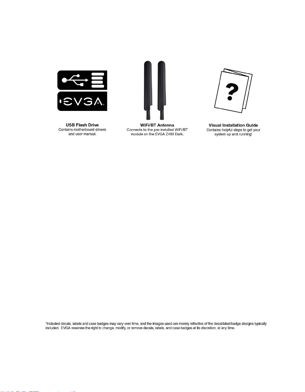
Unpacking and Parts Descriptions
The following accessories are included with the EVGA Z490 DARK
Motherboard:
EVGA Z490 DARK (131-CL-E499)
- 9 -

EVGA Z490 DARK (131-CL-E499)
- 10 -
EVGA Z490 DARK Motherboard LED
reference
The EVGA Z490 DARK Motherboard has several LEDs indicating power, connectivity,
and activity. Below is the location of the LEDs and their function.
EVGA Z490 DARK (131-CL-E499)
- 11 -
1. M.2 Key-E Socket1 32mm
a. WHITE: M.2 can be used.
2. Multifunction POST Indicator
a. During boot it will cycle many different hexadecimal post codes with a
range of 00-FF and this indicates what aspect of the Power On Self Test
(POST) is currently running.
i. For a list of POST Codes, please see Page 157.
b. This indicator can be configured in BIOS to display hardware monitoring
information, such as voltage or temperature. After boot, these LEDs will
show either temperature or voltage, depending on user configuration in
the BIOS.
3. Memory DIMM 2 Status
a. OFF: DIMM detected and present
b. RED: DIMM/Memory has failed POST
4. Memory DIMM 1 Status
a. OFF: DIMM detected and present
b. RED: DIMM/Memory has failed POST
5. +5V Standby Power
a. WHITE: Voltage present (Does not mean PSU is outputting in-spec,
only that this specific voltage is detected)
6. CATERR - Catastrophic Error on the processor
a. RED: Processor error has occurred.
b. OFF: No error state detected in the CPU.
1. M.2 Key-E Ena bled 13. VCCST Status 25. M.2 Key-M PM1 Enabled
2. Multi-function POST indicator 14. VCCSTG Sta tus 26. U.2 PU1 Status
3. Memory DIMM 2 Status 15. VCCIO_1_2 Status 27. U.2 PU1 Enabled
4. Memory DIMM 1 Status 16. Power Button 28. PE2 Status
5. +5V Standby Power 17. Reset Button 29. PE2 Enabled
6. CATERR 18. BIOS 1 Active 30. M.2 Key-M PM2 Status
7. VCORE Status 19. BIOS 2 Active 31. M.2 Key-M PM2 Enabled
8. VDIMM Sta tus 20. BIOS 3 Active 32. PE3 Status
9. VSA Sta tus 21. SW Slow Mode ON 33. PE3 Enabled
10. VCCIO Status 22. PE1 Status 34 PE4 Status
11. VCCPLL Status 23. PE1 Enabled 35 PE4 Enabled
12. VPLL_OC Status 24. M.2 Key-M PM1 Status
LED Legend

EVGA Z490 DARK (131-CL-E499)
- 12 -
7. VCORE status
a. WHITE: Voltage present (Does not mean PSU is outputting in-spec,
only that this specific voltage is detected)
8. VDIMM status
a. WHITE: Voltage present (Does not mean PSU is outputting in-spec,
only that this specific voltage is detected)
9. VSA Status
a. WHITE: Voltage present (Does not mean PSU is outputting in-spec,
only that this specific voltage is detected)
10. VCCIO Status
a. WHITE: Voltage present (Does not mean PSU is outputting in-spec,
only that this specific voltage is detected)
11. VCCPLL Status
a. WHITE: Voltage present (Does not mean PSU is outputting in-spec,
only that this specific voltage is detected)
12. VPLL_OC Status
a. WHITE: Voltage present (Does not mean PSU is outputting in-spec,
only that this specific voltage is detected)
13. VCCST Status
a. WHITE: Voltage present (Does not mean PSU is outputting in-spec,
only that this specific voltage is detected)
14. VCCSTG Status
a. WHITE: Voltage present (Does not mean PSU is outputting in-spec,
only that this specific voltage is detected)
15. VCCIO_1_2 Status
a. WHITE: Voltage present (Does not mean PSU is outputting in-spec,
only that this specific voltage is detected)
b. Inactive with Comet Lake-S processors.
16. Power Button
a. RED: Motherboard is turned on and running.
17. Reset Button
a. WHITE: Reset button will typically flash in conjunction with HDD/SSD
LED. Depending on load, the button may flash or appear solid at times.
b. NVMe SSDs cannot be read for the purposes of the Reset LED.
18. BIOS1 Active LED
a. WHITE: Active BIOS Chip (only 1 will be lit at a time)
19. BIOS2 Active LED
a. WHITE: Active BIOS Chip (only 1 will be lit at a time)

EVGA Z490 DARK (131-CL-E499)
- 13 -
20. BIOS3 Active LED
a. WHITE: Active BIOS Chip (only 1 will be lit at a time)
21. SW Slow Mode ON
a. RED: Slow Mode switch has been set to enabled
22. PCIe Status for PE1. The LED stays off when PE1 is disabled or unpopulated.
a. WHITE: PE1 slot can be used with installed CPU.
23. PCIe Enabled for PE1. The LED stays off when PE1 is disabled or unpopulated.
a. GREEN: PE1 device present and detected.
24. M.2 Key-M Socket3 110mm (PM1) Status LED. The LED stays off when PM1
is disabled or unpopulated.
a. WHITE: PM1 slot can be used with installed CPU.
25. M.2 Key-M Socket3 110mm (PM1) Enabled LED. The LED stays off when PM1
is disabled or unpopulated.
a. GREEN: PM1 device present and detected.
26. U.2 PU1 Status
a. WHITE: Port is enabled.
b. OFF: No device is attached/Port is disabled.
27. U.2 PU1 Enable
a. GREEN: Port is connected to a working device.
b. OFF: No device is attached/Port is disabled.
28. PCIe Status for PE2. The LED stays off when PE2 is disabled or unpopulated.
a. WHITE: PE2 slot can be used with installed CPU.
29. PCIe Enabled for PE2. The LED stays off when PE2 is disabled or unpopulated.
a. GREEN: PE2 device present and detected.
30. M.2 Key-M Socket3 110mm (PM2) Status LED. The LED stays off when PM2
is disabled or unpopulated.
a. WHITE: PM2 slot can be used with installed CPU.
31. M.2 Key-M Socket3 110mm (PM2) Enabled LED. The LED stays off when
PM2 is disabled or unpopulated.
a. GREEN: PM2 device present and detected.
32. PCIe Status for PE3. The LED stays off when PE3 is disabled or unpopulated.
a. WHITE: PE3 slot can be used with installed CPU.
33. PCIe Enabled for PE3. The LED stays off when PE3 is disabled or unpopulated.
a. GREEN: PE3 device present and detected.
34. PCIe Status for PE4. The LED stays off when PE4 is disabled or unpopulated.
a. WHITE: PE4 slot can be used with installed CPU.
35. PCIe Enabled for PE4. The LED stays off when PE4 is disabled or unpopulated.
a. GREEN: PE4 device present and detected.
EVGA Z490 DARK (131-CL-E499)
- 14 -
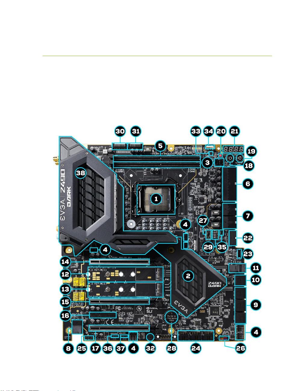
EVGA Z490 DARK Motherboard Component
Legend
The EVGA Z490 DARK Motherboard with the Intel® Z490 and PCH Chipset.
Figure 1 shows the motherboard and Figure 2 shows the back panel connectors
FIGURE 1. Z490 DARK Motherboard Layout
EVGA Z490 DARK (131-CL-E499)
- 15 -
**For a FULL description of the above legend, please see Page 17.
1.
CPU Socket LGA1200
14.
PCIe Slot x16/x8
27.
BIOS Selector Switch
2.
Intel Z490 PCH
15.
PCIe Slot x8/x4
28.
CMOS Battery
3.
PWM Fan Headers (2 amp)
16.
PCIe Slot x4
29. PCIe Disable Switches
4.
PWM/DC Fan Headers (2 amp)
17.
PCIe Slot x4 (x16 Mechanica l)
30. ProbeIt Header J3
5.
DDR4 Memory DIMM Slots 1, 2
18.
Power Button
31.
ProbeIt Header J5
6.
24-pin ATX Power Connector
19.
Reset Button
32.
PC Speaker
7.
8 pin EPS Power Connector
20. CMOS Reset Button 33. BIOS Safeboot Button
8.
Supplemental PCIe 6 pin power
21. Multi-function POST Indicator 34.
USB to SPI for BIOS Fla sh
9.
Intel Sata 6G RAID Ports
22.
USB 3.2 Gen1 Header
35.
SW Slow Switch
10.
ASMedia Sata 6G Ports
23.
USB 3.2 Gen2 Type-C Header
36.
RGB LED Controller Header
11.
U.2 (SFF-8643) Port
24.
USB 2.0 Headers
37.
ARGB LED Controller Hea der
12.
M.2 Socket 3 Key-M 110mm (PM1)
25.
Front Panel Audio Connector
38.
Rear Panel I/O (Figure 2)
13.
M.2 Socket 3 Key-M 110mm (PM2)
26.
Front Panel Connectors
Component Legend

EVGA Z490 DARK (131-CL-E499)
- 16 -
Figure 2. Chassis Rear Panel Connectors
1. PS/2 (Keyboard+Mouse) 5. Intel i219V GbE NIC 9. USB 3.2 Gen2 Type-C
2. USB 3.2 Gen1 6. Intel i225V 2.5GbE NIC 10. Optical Out
3. Intel® WiFi/BT 7. USB 3.2 Gen2 Type-A 11. Ana log Audio Jacks
4. BIOS/CMOS Reset 8. Mini-DisplayPort
I/O Hub
Intel i225V
Activity LED Status Description Speed/Link LED Status Description
Off No Data Transmission Orange 2.5Gbps data rate
Blinking (Green) Data Transmission Green 1 Gbps data rate
Off 10/100 Mbps data rate or No Link
Intel i219V
Activity LED Status Description Speed/Link LED Status Description
Off No Data Transmission Orange 1000Mbps data rate
Blinking (Green) Data Transmission Green 100 Mbps data rate
Off 10 Mbps data rate or No Link

EVGA Z490 DARK (131-CL-E499)
- 17 -
Component Legend Descriptions
1. CPU Socket 1200
This is the interface for the Central Processing Unit (CPU), and supports 10th
Gen. Intel Core i3, i5, i7 and i9 models compatible with the Intel® LGA1200
Socket, based on Comet Lake-S architecture.
2. Intel® Z490 PCH
The Platform Controller Hub (PCH) handles the role that was previously held
by the South Bridge. The PCH has 4 PCIe Gen 3 lanes and allocates bandwidth
to smaller PCIe slots, M.2, USB, audio, etc. In simplified terms, the PCH works
as a hub for peripherals that are less bandwidth-intensive.
3. PWM Fan Headers
4-pin fan headers that control the fan speed based on a configurable curve or
static percentage. PWM (Pulse-Width Modulation) works by pulsing power to
the fan at a constant rate and sending the RPM signal to the fan’s controller via
a Sense cable, rather than adjusting fan speed by increasing and decreasing
voltage. This method is preferable because it eliminates voltage-based fan stall
points. Please see Page 92 for more in-depth PWM breakdown and PWM
controls within BIOS/UEFI.
These headers also support 12v. DC fans. However, DC fan speed is based on
decreasing voltage to the fan, starting at a default of 100%/12V. When using a
12v. fan, the minimum speed will vary depending on the motor because most
fan motors require a set amount of voltage before stalling.
4. PWM/DC Fan Headers
These ports may be used with both DC and PWM fans, and may be controlled
via Smart Fan or manually within the BIOS.
5. DDR4 Memory Slots
The memory slots support up to two 288-pin DDR4 DIMMs in Dual-Channel
mode. Dual-Channel mode will be enabled only upon using two sticks of
supported memory; using one stick of memory will lower the board to SingleChannel mode, which may significantly lower performance. 64GB of RAM is
supported in a 2x32GB configuration. At the time of this manual’s release, this
motherboard officially supports up to 4800MHz+ speeds. These speeds cannot
be guaranteed, however, because Intel® only certifies the speed of the memory
controller up to 2933MHz for Comet Lake-S processors.

EVGA Z490 DARK (131-CL-E499)
- 18 -
6. 24-pin ATX power connector
The main power for the motherboard is located on the right side of the board
and parallel to the PCB; this is also described as a “90 degree / right-angle”
connector (See Page 41 for more specifics to the connector itself, and associated
wiring/pinouts). The 24-pin connector IS directional and the connector needs
the tab on the socket to line up with the release clip located on the 24-pin
connector from the power supply. This connector pulls the bulk of the power
for all components; other connectors, such as EPS and PCIe, have been added
to reduce the load and increase longevity due to wiring and trace limitations.
7. Dual 8-pin EPS Connectors
The +12V EPS are comprised of 90 degree right-angle dual-dedicated power
inputs for the CPU (See Page 42 for more specifics to the connector itself, and
associated wiring/pinouts). Carefully choose the correct power cable by
consulting with the installation manual for your power supply. This connector
is designed only to work with an EPS or CPU cable. System builders may make
the mistake of plugging in a PCIe 8-pin or 6+2-pin connector, which will
prevent the board from POSTing and possibly short or damage the board.
Although the cables appear similar, they are wired differently and attaching a
PCIe cable to an EPS connector may cause damage to the motherboard.
Alternatively, if no power cable is connected or detected, the system will not
POST and will hang at POST code “C.”
8. Supplemental PCIe 6-pin Power Connector
There is a 6-pin PCIe connector at the bottom of the motherboard (See Page 41
for more specifics to the connector itself, and associated wiring/pinouts). This
connector provides dedicated power to the PCIe x16 slots, augmenting the
+12V power provided by the 24-pin and the GPU directly.
This is optional for a single card solution, but is recommended for SLI, CFX,
and dual-processor video cards.
9. Intel® SATA 6Gbit/s Ports
The Intel® Z490 PCH has a 6-port SATA 3/6 Gbit/s controller (See Page 51
for specifics on the connectors). This controller is backwards compatible with
SATA and SATA II devices, and supports SSDs, HDDs and various types of
optical devices (CDROM, DVDROM, BD-ROM, etc). The controller also
supports NCQ, TRIM, hot swap capability, and RAID levels 0/1/5/10.

EVGA Z490 DARK (131-CL-E499)
- 19 -
10. ASMedia SATA 6Gbit/s Ports
This is a secondary SATA controller, the ASM1061 is a 2-port SATA3/6
Gbit/s controller with legacy support for older operating systems. This is
included largely for benchmarking and overclocking with very specific
programs, such as Super Pi, 3DMark, PCMark, etc. This board is not
guaranteed to fully support any OS prior to Windows 10 x64, as we offer no
drivers for legacy OS (See Page 51 for specifics on the connectors).
11. U.2 Port (SFF-8643)
U.2, originally known as SFF-8643, is a high bandwidth connection specifically
engineered for next generation SSDs. U.2 brings PCIe x4 (Gen3) NVMe
performance to a 2.5” SSD form factor and provides a solution to potential
heating problems that may be present in some M.2 solutions. Port function
depends upon BIOS Configuration. Note: SFF-8643 ports are located on the
motherboard side; SFF-8639 ports are located on the storage side.
12. M.2 Socket 3 Key-M 110mm (PM1)
M.2 is an SSD form factor standard, which uses up to four PCIe lanes and
utilizes Gen3 speeds. Most popularly paired with NVMe SSDs, this standard
offers substantially faster transfer speeds and seek time than SATA interface
standards. All M.2 devices are designed to connect via a card-bus style
connector and be bolted into place and powered by the connector, rather than
by a dedicated data cable and power cable.
This socket will support Key-M devices of 110mm, 80mm, 60mm, and 42mm
length.
This connector can utilize only PCIe/NVMe-based M.2 SSDs, or Intel®
Optane™ NVMe devices.
13. M.2 Socket 3 Key-M 110mm (PM2)
M.2 is an SSD form factor standard, which uses up to four PCIe lanes and
utilizes Gen3 speeds. Most popularly paired with NVMe SSDs, this standard
offers substantially faster transfer speeds and seek time than SATA interface
standards. All M.2 devices are designed to connect via a card-bus style
connector and be bolted into place and powered by the connector, rather than
by a dedicated data cable and power cable.
This socket will support Key-M devices of 110mm, 80mm, 60mm, and 42mm
length.
This connector can utilize only PCIe/NVMe-based M.2 SSDs, SATA M.2, or
Intel® Optane™ NVMe devices.

EVGA Z490 DARK (131-CL-E499)
- 20 -
14. PCIe Slot x16/x8*
PCIe x16/x8 slots are primarily used for video cards. These full-length slots
will provide 8 or 16 lanes of bandwidth to a full-size card, and are backwardscompatible with x8, x4, and x1-length cards.
Comet Lake-S has 16 PCIe lanes available for routing.
15. PCIe Slot x8/4*
PCIe x8/4 slot can be used for video cards or other devices. PE2, the only
x8/x4 slot on the board, receives either x8 lanes or x4 from the CPU (Page
27), depending upon the peripheral configuration. These full-length slots will
provide up to 8 lanes of bandwidth to a full-size card, and are backwardscompatible with x8, x4, and x1-length cards.
Comet Lake-S has 16 PCIe lanes available for routing.
16. PCIe Slot x4*
PCIe x4 slot PE3 uses up to 4 Gen 3 lanes from the PCH. This slot is typically
used for sound cards, WiFi, USB, LAN or other peripheral cards. Using this slot
will have no effect on the bandwidth or throughput of the x16 slots used for
SLI because this slot uses only PCH bandwidth.
17. PCIe Slot x4* (x16 Mechanical)
PCIe x4 slot can be used for video cards or other devices. PE4, the only full
x16 mechanical slot that runs at x4 electrically, receives either x4 lanes or x0
from the CPU (Page 27), depending upon the peripheral configuration. These
full-length slots will provide up to 4 lanes of bandwidth to a full-size card, and
are backwards-compatible with x1-length cards.
PCIe x4 slot PE4 uses up to 4 Gen 3 lanes from the CPU. This slot shares 4
lanes with PE2, and will change both PE2 and PE4 to x4 lanes. Using this slot
will disable SLI because SLI requires at least 2 slots capable of x8 bandwidth.
Comet Lake-S has 16 PCIe lanes available for routing.
18. Power Button
This is an onboard power button, and may be used in place of, or in
conjunction with, a front panel power button wired to the board.
Benching systems, or test benches before final assembly, are best served by
using the onboard power because it removes the need to wire a Power/Reset
button or cross posts with a screwdriver, which is a semi-common practice.
This button provides a safer and easier option than jumpering the Power posts.

EVGA Z490 DARK (131-CL-E499)
- 21 -
19. Reset Button
This is an onboard system reset button, and may be used in place of, or in
conjunction with, a front panel system reset button wired to the board.
Benching systems, or test benches before final assembly, are best served by
using the onboard power because it removes the need to wire a Power/Reset
button or cross posts with a screwdriver, which is a semi-common practice.
This button provides a safer and easier option than jumpering the Power posts.
20. CMOS Reset Button
This button has two main uses: the first is standard practice to clear BIOS and
power on before updating the BIOS, and the second is standard practice when
troubleshooting instances when the motherboard fails to POST, such as after
upgrading RAM or CPU, installing new hardware, a failed overclock, etc. This
button provides a much faster means of resetting than the previous method of
removing power from the board, removing the CMOS battery, and discharging
power to the board. In rare occasions the older method can help; pressing the
clear CMOS button will normally allow you and your system back into the
default BIOS.
21. Multi-function POST Indicator
This is a four-digit POST code reader, which displays in sets of 7-digit LED.
The display can be configured to show data in regular decimal format, or
hexadecimal, which means the characters available (when working as intended)
are 0-9, A-F and has a cap of 255 characters.
During POST, the left set of LEDs will display the various POST codes as they
cycle through the Power On Self-Test. The POST codes are listed in the
troubleshooting section on Page 157.
After the system boots, these same set of LEDs can be set to display a hardware
monitoring sensor, such as the CPU temperature in Celsius. This temperature
is specifically for the CPU socket, which will typically read slightly higher than a
given CPU core. To read this temp in Fahrenheit, take the value in Celsius,
multiply by 9/5 (or 1.8) and add 32.
The display can be used to show additional temperatures, or can be configured
in tandem with all 4 digits to provide live readings for voltages or temperatures.
For example, the LEDs can be configured to read voltages, such as 1.258 or 55C for CPU temp for when you are using LN2 extreme cooling. Detailed
configuration instructions for the Debug Indicator are provided on Page 153.

EVGA Z490 DARK (131-CL-E499)
- 22 -
22. USB 3.2 Gen1 Header
The USB 3.2 Gen1 header is used to connect additional USB interface plugs to
the motherboard; these headers are most often used to connect the
motherboard to the chassis to enable the USB 3.2 Gen1 ports on the chassis.
These will function similarly to the USB 3.2 Gen1 ports found on the
motherboard’s rear I/O hub, but can also be used for the chassis’ front panel
USB, auxiliary ports that mount in the card slots, and certain devices that
directly connect to the header.
USB 3.2 Gen1 standard is 900ma @ 5V for unpowered devices. If your USB
device requires more power, it is recommended to attach a powered USB Hub.
USB 3.2 Gen2 Type-A (found on the I/O Hub) shares the power limit of USB
3.2 Gen1 at 900ma @ 5V.
Note: USB 3.2 Gen1 is more commonly referred to as USB 3.0.
23. USB 3.2 Gen2 Type-C Header
The USB 3.2 Gen2 header is used to connect additional USB interface plugs to
the motherboard; these headers are most often used to connect the
motherboard to the chassis to enable the USB 3.2 Gen2 ports on the chassis.
These will function similarly to the USB 3.2 Gen2 Type-C port sometimes
found on a motherboard’s rear I/O hub, but can also be used for the chassis’
front panel USB, auxiliary ports that mount in the card slots, and certain
devices that directly connect to the header. The USB 3.2 Gen2 Header on the
Z490 DARK is a shielded USB 3.2 Gen2 Header and supports up to 10Gb/s
with USB 3.2 Gen2.
This USB 3.2 Gen2 Header has a power limit of 3000ma (3A) @ 5V.
24. USB 2.0 Headers
The USB2.0 header is used to connect additional USB interface plugs to the
motherboard; these headers are most often used to connect the motherboard to
the chassis to enable the USB2.0 ports on the chassis. These will function the
same as the USB2 ports found on the motherboard’s hardwired I/O hub, but
these can be used to attach to front panel USB, auxiliary ports that mount in the
card slots, and also some devices that directly connect to the header.
USB 2.0 standard is 500mA @ 5V per port (header total is 1000mA) for
unpowered devices. If your USB device requires more power than this, it is
recommended to attach a powered USB Hub.

EVGA Z490 DARK (131-CL-E499)
- 23 -
25. Front Panel Audio Connector
This is a motherboard header, which is used to plug in the audio cable
originating from most PC chassis to allow audio to be recorded from or played
through the audio connectors on the chassis. This header has a connector that
looks similar to the USB2.0 header and uses the standard “HD Audio” jack.
Some chassis may have two cables: HD Audio, and one labeled AC’97 – an
AC’97 cable is not compatible with this header on the Z490 DARK.
26. Front Panel Connectors
The Front panel connectors are the four main chassis connections. These
include the Power Switch, Power LED, Reset Switch, and HDD LED. The
Power and Reset switches are both designed to use “Momentary Switches,”
rather than “Latching Switches,” which means the connection between the two
posts needs to be made just briefly for it to work, as opposed to being held in
place. This is why the Power and Reset switches can be triggered with a screw
driver by simultaneously touching the + and - posts.
Power LED will power on with the system, indicating the system is on and can
blink with CPU activity.
HDD LED will blink during access to the SATA ports; this is not activated for
M.2 SSDs.
27. BIOS Selector Switch
This switch toggles between physical BIOS chips. This board has 3 BIOS chips
as a permanent fixture. Each chip holds only the settings and profiles that have
been saved to the BIOS chip while active. This allows you to swap between
three physically different BIOS chips. Similarly, you can update each BIOS via
the USB Update Port, even if you cannot POST into BIOS. If instructions are
needed for updating the BIOS via the Update Port, please go to Page 147.
28. CMOS Battery
The +3V CMOS battery backup provides uninterruptable power to the
BIOS/UEFI to keep all of the settings; otherwise, each boot would behave like
you just reset the BIOS. These batteries typically last several years and rarely
need to be replaced.
29. PCIe Disable Switches
These are DIP switches to physically disable power to a specific PCIe slot. By
default, all switches are in the “On” position to the left. Move the switch to the
right to disable a specific slot. From top to bottom, the switches correspond to
PE1, PE2, and PE4. PE3 is always on. Switches 4 and 5 are disabled.

EVGA Z490 DARK (131-CL-E499)
- 24 -
30. ProbeIt Header J3
The ProbeIt header is a means of live monitoring several different system
voltages in real-time with a multimeter. One terminal needs to connect to a
ground wire and the other to the specific voltage you want to monitor.
From left to right the function for the J3 connector: VCORE/Ground,
VDIMM/Ground, VGT/Ground, VSA/Ground, and VCCIO/Ground.
31. ProbeIt Header J5
The ProbeIt header is a means of live monitoring several different system
voltages in real-time with a multimeter. One terminal needs to connect to a
ground wire and the other to the specific voltage you want to monitor.
From left to right the function for the J5 connector: VCCPLL/Ground,
VCCPLL_OC/VCCSTG, VCCST/VCCIO12, PCH/Ground, and
DMI/Ground.
32. PC Speaker
This is a small mono low-fidelity speaker permanently attached to the
motherboard used mainly for debugging purposes. A POST beep may indicate
a successful POST, various tones for USB initialization, and other beeps to
indicate an issue during the post process. Please see Page 155 for more details.
33. BIOS SafeBoot Button
Pressing this button while the system is running will reboot the motherboard
directly into the BIOS without clearing CMOS. This feature is very useful for
situations where the motherboard is unable to complete boot due to a failed
overclock and the user does not want to erase the previous settings used.
34. USB to SPI for BIOS Flash
This USB port is designed to connect directly to the motherboard to allow the
motherboard BIOS to be flashed, even if no CPU is installed. For more
information on how to flash your BIOS using this method, please see Page 147.
35. SW Slow Mode Switch
This switch forces the CPU clock ratio to the lowest possible value (8.0 for
Comet Lake-S CPU) in real-time. This can be helpful for benchmarking and
performance tuning, especially with extreme overclocking. Active Slow Mode is
indicated by a red LED near the switch. This is a hardware-based function and
does not need any BIOS settings or software to operate.

EVGA Z490 DARK (131-CL-E499)
- 25 -
36. RGB LED Controller Header
The RGB header is a 12V. 4 pin header with a current limit of 2A; anything
above 2A will trigger overcurrent protection and lock at 2A. This header allows
for software-based control within Windows for RGB devices via EVGA
ELEET X1. Please see Page 46 for header specifics, and Page 139 for control
options in ELEET X1.
37. ARGB LED Controller Header
The ARGB header is a 5V. 3 pin header with a current limit of 2A; anything
above 2A will trigger overcurrent protection and lock at 2A. This header allows
for far more flexible options to configure your RGB lighting via software-based
control within Windows via EVGA ELEET X1, and supports up to 125 LEDs.
Please see Page 45 for header specifics, and Page 139 for control options in
ELEET X1.
38. Rear Panel IO (Figure 2)
This is the section referred to as the I/O Hub. This panel contains the
hardwired USB, Sound, and Ethernet connections. Please see Page 16 for a
component level breakdown.
* There are two numeric references for PCI Express: one is mechanical, which is the
actual slot-length footprint, and the second is electrical, which is a reference of how
many PCIe lanes are routed to the slot.
Because PCI-Express was designed to be a universal architecture, you can install x1
cards, such as sound cards or USB controllers into an x16 slot. Many types of cards can
use different amounts of PCIe lanes, while some applications use only certain parts of a
card, such as compute apps that allow a card to run off of a single PCIe lane. This is
why there are x16 mechanical slots with an x1 electrical PCIe lane. Using the entire
length of a PCIe slot is unnecessary, nor does it cause an adverse effect to use a shorter
form-factor bus card in a slot that physically can hold a larger form-factor bus card.
EVGA Z490 DARK (131-CL-E499)
- 26 -
Card Slots
The Z490 DARK features three x16 PCIe slots, one x4 PCIe slot, two Socket 3
Key-M M.2 110mm slots (PM1/PM2) (backwards compatible with Key-M 80mm,
60mm, and 42mm), and a vertical Socket 1 Key-E M.2 (Contains the WiFi module).
*Note: The M.2 Key-E 32mm slot is accessible only after removing the cover over
the rear panel connectors.

EVGA Z490 DARK (131-CL-E499)
- 27 -
PCIe Slot Breakdown
PCIe Lane Distribution (All Socket 1200
processors are 16 lanes.)
PE1 – x16 (Gen3, x16 lanes from CPU, x8 shared with PE2)
PE2 – x8 (Gen3, x8 lanes from CPU, x4 shared with PE4)
PE3 – x4 (Gen3, x4 lanes from PCH)
PE4 – x4 (Gen3, x4 lanes from CPU, shares 4 of PE2’s 8 lanes)
M.2 / U.2 Slot Breakdown
M.2 Lane Distribution
M.2 Key-M (110mm, Top, PM1) – x4 from Z490 PCH
o M.2 Enable/Disable is set within the BIOS
o This M.2 Key-M slot shares lanes with the U.2 port. Installing an M.2
device will disable U.2 port PU1.
M.2 Key-M (110mm, Bottom, PM2) – x4 from Z490 PCH
o M.2 Enable/Disable is set within the BIOS
o This M.2 Key-M slot shares lanes with PE3. Installing an M.2 device will
disable PCIe slot PE3.
M.2 Key-E (32mm) – x1 from Z490 PCH
o M.2 Enable/Disable is set within the BIOS
U.2 Lane Distribution
U.2 (PU1) – x4 from Z490 PCH
o U.2 Enable/Disable is set within the BIOS
o This U.2 port shares lanes with the M.2 Key-M slot PM1. Installing a
U.2 device will disable PM1.
EVGA Z490 DARK (131-CL-E499)
- 28 -
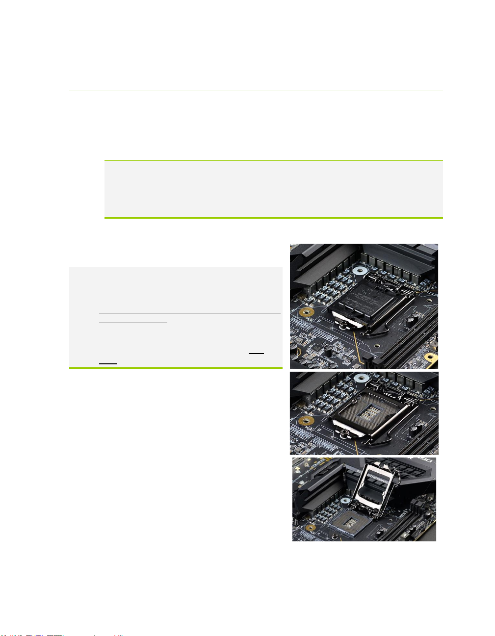
Preparing the Motherboard
Installing the CPU
Note: EVGA strongly recommends that you completely disconnect AC power from
your power supply prior to changing your CPU. This ensures the
motherboard will use the correct startup procedure for all onboard devices. If
AC power is not disconnected, the replacement is still supported, but may
require additional reboots to boot successfully.
Be very careful when handling the CPU. Hold the processor only by the edges and do
not touch the bottom of the processor.
Note: Use extreme caution when working with the
CPU to avoid damaging the pins in the
motherboard’s CPU socket!
Do not remove the socket cover until you have
installed the CPU. This installation guide was
created without using a socket cover to better
illustrate the CPU Socket area. However,
users should remove the cover as the last
step, not the first step.
Use the following procedure to install the CPU
onto the motherboard.
1. Unhook the socket lever by pushing
down and towards the socket.
2. Pull the socket levers back and gently lift
the load plate to open the socket. Make
sure to avoid touching or dropping items
into the socket; otherwise, you may
damage the board socket and/or CPU
pins, which may void your warranty.

EVGA Z490 DARK (131-CL-E499)
- 29 -
3. Align the notches on the CPU to the
notches in the socket, and lower the
processor straight down into the socket.
Note: The gold triangle key on the CPU
should match the triangle key on
the load plate.
Note: Make sure the CPU is fully seated
and level in the socket.
4. Lower the load plate so that it is resting
on the CPU.
5. Carefully lock the lever back into place
by lowering it down to the hook, then
push the lever towards the socket and
down under the hook.
6. Remove the plastic protective socket
cover by pulling it straight up and away
from the socket.
Note: After removing the CPU socket cover, it is recommended to store it in case
you ever need to transport your motherboard. If you ever remove the CPU, it
is highly recommended to reinstall the socket cover.
Installing the CPU Cooling Device
There are many different cooling devices that can be used with this
motherboard. Follow the instructions that come with your cooling assembly.

EVGA Z490 DARK (131-CL-E499)
- 30 -
Installing System Memory
Your Z490 DARK has (2) 288-pin slots for
DDR4 memory. These slots support 4GB,
8GB, 16GB, and 32GB DDR4 Unbuffered
non-ECC DIMMs. There must be at least
one memory slot populated for the board to
boot and operate.
The Z490 DARK supports Dual-Channel
DDR4 memory, a maximum of 64GB and
up to 4800MHz+ (OC) for Comet Lake-S.
It is recommended to always use a 2 DIMM
Dual Channel kit for the Z490 DARK.
Fill the memory slots in the following
order: 1, then 2. See chart to the right:
Use the following procedure to install
memory DIMMs. Note that there is a
key notch near the center of the DIMM slots. This matches the gap on
a DDR4 DIMM to ensure the memory is installed properly, and to prevent the
incorrect installation of memory.
1. Unlock a DIMM slot by pressing the module clips outward.
2. Align the memory module to the DIMM slot, insert the module
vertically into the slot, and press straight down to fully seat the module.
The plastic clips at top side of the DIMM slot should automatically
lock the DIMM into the connector.
Note: The memory controller on most Comet Lake-S CPUs runs at a default
frequency of 2933MHz on 10- and 8-core processors, but only 2666MHz on
6-core processors. Achieving memory speeds above the CPU’s default speed
may require manual setting of the memory timings, frequency and voltages
and/or overclocking of the CPU.
Refer to the memory manufacturer specifications for the recommended
memory timings. For overclocking support you can visit our forums:
https://forums.evga.com/
Slot 1 Slot 2
1 DIMM
X N/A
2 DIMM
X X
Comet Lake-S RAM Slot Fill Order
 Loading...