


EVCO S.p.A. EVFTFT618 | Installer manual ver. 2.2 | Code 144FTFT618E224
EVFTFT618
Split execution controller for management
of retarder-proofer cabinets/cells with
capacitive type user interface and TFT
graphic display
ENGLISH
INSTALLER MANUAL ver. 2.2
CODE 144FTFT618E224
Page 1 of
62

EVCO S.p.A. EVFTFT618 | Installer manual ver. 2.2 | Code 144FTFT618E224
Important
Important
Read this document thoroughly before installation and before use of the device and follow all recommendations; keep
this document with the device for future consultation.
The following symbols support reading of the document:
indicates a suggestion
indicates a warning.
The device must be disposed of in compliance with local Standards regarding the collection of electric and electronic
equipment.
Page 2 of
62

EVCO S.p.A. EVFTFT618 | Installer manual ver. 2.2 | Code 144FTFT618E224
Index
1
INTRODUCTION ................................................................................................................................... 5
1.1 Introduction ........................................................................................................................................ 5
1.2 Summary table of the main features and the models available ................................................................... 6
2
DESCRIPTION ...................................................................................................................................... 8
2.1 Description of the user interface ............................................................................................................ 8
2.2 Description of the control module ........................................................................................................... 9
3
DIMENSIONS AND INSTALLATION ........................................................................................................ 10
3.1 User interface dimensions ................................................................................................................... 10
3.2 Control module dimensions ................................................................................................................. 10
3.3 User interface installation .................................................................................................................... 11
3.4 Control module installation .................................................................................................................. 11
3.5 Installation warnings .......................................................................................................................... 11
4
ELECTRIC CONNECTION ...................................................................................................................... 12
4.1 Electric connection ............................................................................................................................. 12
4.1.1 Connection of the terminating resistors of the communication port ................................................... 13
4.1.2 Insertion of the RS-485 serial port terminating resistor ................................................................... 14
4.2 Warnings for the electric connection ..................................................................................................... 14
5
USER INTERFACE ............................................................................................................................... 15
5.1 Preliminary notes ............................................................................................................................... 15
5.2 Device commissioning ........................................................................................................................ 15
5.3 Switching the Device On/Off ................................................................................................................ 16
5.4 The display ........................................................................................................................................ 16
6
OPERATION ....................................................................................................................................... 17
6.1 Preliminary notes ............................................................................................................................... 17
6.1.1 Pre-selection page ...................................................................................................................... 19
6.1.2 Setting and execution of a manual cycle ........................................................................................ 20
6.1.3 Setting an automatic cycle ........................................................................................................... 21
6.1.4 Execution of an automatic cycle ................................................................................................... 22
6.1.5 The PROGRAMS menu ................................................................................................................. 23
6.1.5.1 Modify Date and Time of Automatic Cycle End .................................................................... 23
6.1.6 The FAVOURITES menu ............................................................................................................... 24
6.1.7 The PRE-COOLING menu ............................................................................................................. 25
6.1.8 The PRE-SELECTION PAGE OPTIONS menu .................................................................................... 26
6.1.8.1 The SERVICE menu ................................................................................................................ 27
7
Detail Meaning Icons Status Regulators ................................................................................................ 28
7.1
Silencing the buzzer ........................................................................................................................... 28
8
keyboard lock .................................................................................................................................... 28
8.1 Manual keyboard lock ......................................................................................................................... 28
8.2 Automatic keyboard lock ..................................................................................................................... 28
9
Regulations ....................................................................................................................................... 29
9.1 Pre-cooling ........................................................................................................................................ 29
9.2 Temperature regulation ....................................................................................................................... 29
9.2.1 Generating cold .......................................................................................................................... 29
9.2.2 Generating heat ......................................................................................................................... 30
9.3 Regulation of humidity ........................................................................................................................ 30
9.3.1 Humidification management ........................................................................................................ 31
Page 3 of
62

EVCO S.p.A. EVFTFT618 | Installer manual ver. 2.2 | Code 144FTFT618E224
9.3.2
Dehumidification management ..................................................................................................... 31
10
Loads management ............................................................................................................................ 31
10.1 Management of the compressor ....................................................................................................... 31
10.2 Pump-down management ................................................................................................................ 31
10.3 Management of the evaporator fan ................................................................................................... 32
10.4 Defrosting management .................................................................................................................. 32
10.5 Management of the heating elements ............................................................................................... 33
10.5.1 Cabinet step heating management ............................................................................................... 33
10.6 Management of the steam generator ................................................................................................ 33
10.7 Humidification management ............................................................................................................ 33
10.7.1 Management of humidity without transducer (rU0 = 1) ................................................................... 33
10.7.2 Management of humidity with transducer (rU0 = 0) ........................................................................ 33
10.8 Dehumidification management ......................................................................................................... 34
10.8.1 Management via extractor fan/dehumidifier ................................................................................... 34
10.8.2 Management via cooling plant activation ....................................................................................... 34
10.9 Management of the condenser fan .................................................................................................... 34
10.10 Cabinet light management............................................................................................................... 34
11
Alarms .............................................................................................................................................. 35
12
Management of the Host USB port on the board ..................................................................................... 38
13
Parameters ........................................................................................................................................ 39
14
Accessories ....................................................................................................................................... 47
14.1 Phase cut speed regulator for single phase fans EVDFAN1 ................................................................... 47
14.1.1 Introduction ............................................................................................................................... 47
14.1.2 Description ................................................................................................................................ 47
14.1.3 Dimensions ................................................................................................................................ 48
14.1.4 Connection to the device ............................................................................................................. 48
14.2 Synoptic Panel EVC25T00X7XXX04 ................................................................................................... 48
14.3 Optoisolated RS-485/RS-232 serial interface EVIF21RS7I .................................................................... 50
14.3.1 Introduction ............................................................................................................................... 50
14.3.2 Description ................................................................................................................................ 50
14.3.3 Dimensions ................................................................................................................................ 51
14.3.4 Connection to the device ............................................................................................................. 51
14.4 Non-isolated RS-485/USB serial interface EVIF20SUXI ........................................................................ 52
14.4.1 Introduction ............................................................................................................................... 52
14.4.2 Description ................................................................................................................................ 52
14.4.3 Dimensions ................................................................................................................................ 53
14.4.4 Connection to the device ............................................................................................................. 53
15
TECHNICAL DATA ............................................................................................................................... 54
15.1 Technical data ................................................................................................................................ 54
Page 4 of
62

EVCO S.p.A. EVFTFT618 | Installer manual ver. 2.2 | Code 144FTFT618E224
1 INTRODUCTION
1.1 Introduction
EVFTFT618 is a digital controller studied to manage retarder proofer cabinets/cells, which can be mechanically and
aesthetically integrated into the unit.
The controller is fitted with:
- clock, signal buzzer and alarm
- 4 analogue inputs of which 3 for PTC/NTC probes and 1 for 4-20mA
- 4 digital inputs (door micro switch, compressor circuit breaker, high pressure and low pressure protection)
- 1 PWM analogue output for management of the evaporator fan
- 8 digital outputs (electromechanical relays), 1 x 16 A res. @ 250 VAC for compressor management, 1
x 16 A res. @ 250 VAC for heating element management and 6 x 8 A res. @ 250 VAC for management of the cabinet
light, humidifier, dehumidifier/condenser fan, defrosting, steam generator and pump-down valve/evaporator fan.
- RS-48 serial port with MODBUS communication protocol
- USB port on board.
The controller supplies a complete control for retarder-proofer cabinets or cells for confectionery and bread-making,
through the automatic management of the complete mixture retarder-proofer cycle.
The machine can have 3 different states, defined unmistakeably in the following way through the entire document:
STAND-BY status: the machine is off but powered, it is not possible to perform any selection/cycle start command
ON status: the machine is on but in stand-by for operating cycle selection
RUN status: the machine is on with a cycle in progress
Page 5 of
62

EVCO S.p.A. EVFTFT618 | Installer manual ver. 2.2 | Code 144FTFT618E224
1.2 Summary table of the main features and the models
available
The following table illustrates the main features of the device.
“ / “ indicates the feature can be set via a configuration parameter.
User interface (without cover)
200.0 x 135.0 mm (7.874 x 13.498 cm; L x H) •
320 x 240 pixel
(3.5 inch) colour TFT graphics display
number of keys (capacitive touch-key type) 11
Control module (without cover)
166.0 x 116.0 mm (6.535 x 11.598 cm; L x H) •
Connections
removable screw terminal board •
Power supply
115-230 VAC •
Analogue inputs
cabinet probe PTC/NTC
•
evaporator probe PTC/NTC
condenser probe PTC/NTC
humidity transducer 4-20mA
Digital inputs (for NO/NC contact)
door micro switch •
high pressure •
low pressure •
compressor circuit breaker protection •
Analogue outputs (PWM)
evaporator fan (1)
Page 6 of
62

EVCO S.p.A. EVFTFT618 | Installer manual ver. 2.2 | Code 144FTFT618E224
Digital outputs (electromechanical relays; A res. @ 250 VAC)
compressor 16 A
cabinet light 8 A
humidifier 8 A
dehumidifier/condenser fan 8 A
defrosting 8 A
heating elements 16 A
steam generator 8 A
pump down valve/evaporator fan
8 A
Communication port
RS-48 serial port with MODBUS communication protocol •
USB type serial port •
Other features
IP65 protection rating of the user interface IP65
clock •
signal buzzer and alarm •
management of temperature alarms •
“programs” function •
configuration parameters access password •
restoring the factory settings •
Notes:
(1) The evaporator fan control signal can be analogue or digital.
For further information, see chapter 0 15 TECHNICAL DATA; for other models contact the EVCO sales network.
Page 7 of
62

EVCO S.p.A. EVFTFT618 | Installer manual ver. 2.2 | Code 144FTFT618E224
2 DESCRIPTION
2.1 Description of the user interface
The following drawing illustrates the aspect of the EVFTFT618 user interface.
The following table illustrates the meaning of EVFTFT618 user interface parts.
Part Part
1 on/off key, herein called also "ON/STAND-BY key"
2 options key, hereon call "MENU key"
3 pre-selection key, hereon call "HOME key"
4 annul key, hereon call "ESCAPE key"
5 cycle start/cycle cut-off key, hereon called "START/STOP key"
6 interactive keys
7 display
8 interactive keys
9
10 USB type serial port
RS-485 serial port with MODBUS communication protocol and communication port with control
module (signal and power supply)
11
12 earth
For further information, see the next chapters.
jumper for the insertion of the terminating resistor of the user interface-control module
communication port and of the RS-485 serial port
Page 8 of
62

EVCO S.p.A. EVFTFT618 | Installer manual ver. 2.2 | Code 144FTFT618E224
2.2 Description of the control module
The following drawing illustrates the aspect of the EVFTFT818 control module.
The following table illustrates the meaning of EVFTFT618 control module parts.
Part Part
1 power supply
2 digital outputs K3 and K4
3 digital output K2
4 digital output K1
5 digital output K5
6 digital inputs
7 digital output K6
8 digital outputs K7 and K8
9 reserved
10 reserved
11 reserved
12 Not used
13 analogue inputs (cabinet probe, evaporator probe and condenser probe)
14 Humidity probe
15 PWM analogue output
16 communication port with the user interface (signal and power supply)
For further information, see the next chapters.
Page 9 of
62
EVCO S.p.A. EVFTFT618 | Installer manual ver. 2.2 | Code 144FTFT618E224
partic. A
partic. A
partic. A
partic. A
175,0 (6,889)
180,0 (7,086)
200,0 (7,874)
1
1
0
,
0
(
4
,
3
3
0
)
1
2
2
,
0
(
4
,
8
0
3
)
1
3
5
,
0
(
5
,
3
1
4
)
R
2
,
0
(
0
,
0
7
8
)
1
1
6
,
0
(
4
,
5
6
6
)
1
0
8
,
0
(
4
,
2
5
1
)
1
0
0
,
0
(
3
,
9
3
7
)
8
6
,
0
(
3
,
3
8
5
)
Ø 4,0 (0,157)
Detail A
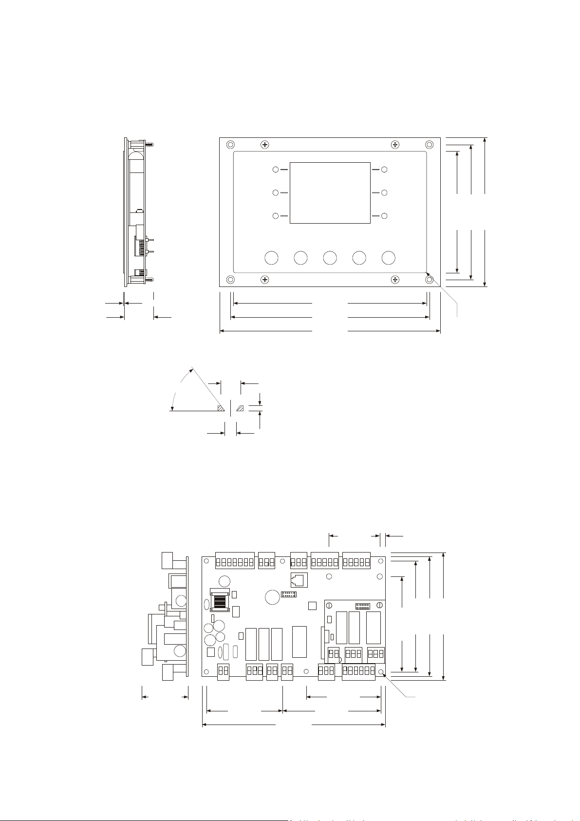
3 DIMENSIONS AND INSTALLATION
3.1 User interface dimensions
The following drawing illustrates the EVFTFT618 user interface dimensions; these are expressed in mm (in).
Det. A Det. A
Det. A Det. A
1,0 ±0,6 (0,039 ±0,023)
27,0 (1,062)
particolare A
°
3
5
4,2 (0,165)
7,2 (0,283)
2.0 (0.078)
3.2 Control module dimensions
The following drawing illustrates the EVFTFT618 control module dimensions; these are expressed in mm (in).
5,0 (0,196)46,0 (1,811)
68,0 (2,677)44,0 (1,732)
69,0 (2,716) 89,0 (3,503)
166,0 (6,535)
Page 10 of
62

EVCO S.p.A. EVFTFT618 | Installer manual ver. 2.2 | Code 144FTFT618E224
3.3 User interface installation
Back panel via studs
3.4 Control module installation
On flat surface, with spacers.
3.5 Installation warnings
- make sure that the device work conditions (temperature of use, humidity, etc.) lie within the limits
indicated; see chapter 0 15 TECHNICAL DATA
- do not install the device near to any heat sources (heating elements, hot air ducts etc.), equipment
containing powerful magnets (large diffusers, etc.), areas affected by direct sunlight, rain, humidity, excessive dust,
mechanical vibrations or shocks.
- any metal parts in proximity of the control module must be at a distance such that they do not
compromise the safety distances; any wiring must be positioned at least 2 cm
- in compliance with Safety Standards, the device must be installed correctly and in a way to protect
against any contact with electric parts; all parts that ensure protection must be fixed in a way that they cannot be
removed without the use of tools.
Page 11 of
62
EVCO S.p.A. EVFTFT618 | Installer manual ver. 2.2 | Code 144FTFT618E224
USB port
RS-485 port
ground
Power supply
Evaporator
humidity
cell
mains
eating
mains
Power supply
Control module
User interface
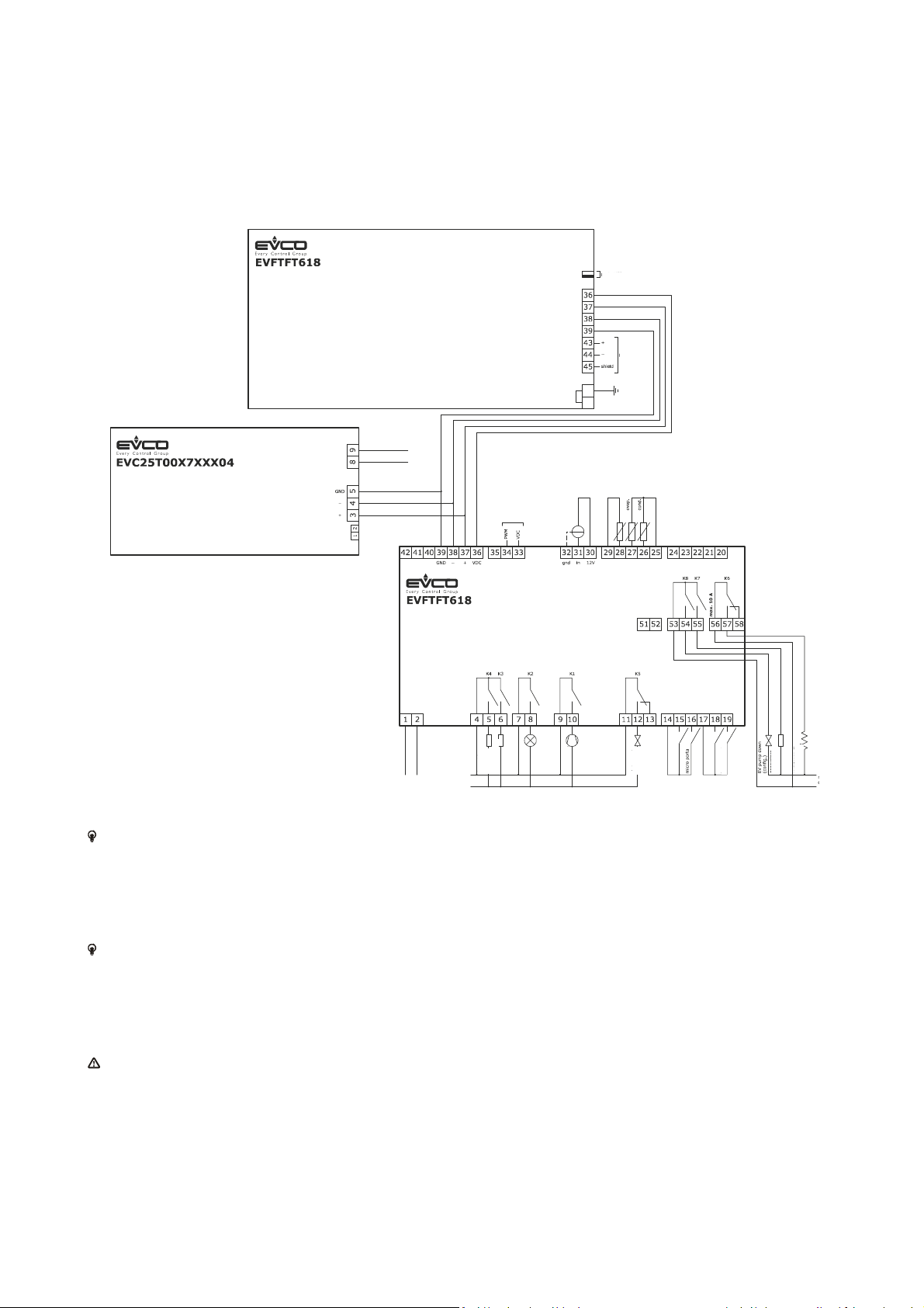
4 ELECTRIC CONNECTION
4.1 Electric connection
The following drawing illustrates the EVFTFT618 electric connection.
fan at
EVCFAN1
electricity
The utility managed by the K4 output, depends on parameter u3, as follows:
- dehumidifier (u3 = 0)
- condenser fan (parameter u3 = 1).
For the settings relative to the parameters, see chapter 0.
The utility managed by the K8 output, depends on parameter u1, as follows:
- pump down valve (u1 = 0, per-defined setting)
- evaporator fan (u1 = 1).
For the settings relative to the parameters, see chapter 0.
The RS-485 port is for the connection of the controller to the following additional products:
- Parameters Manager set-up software system
- RICS plants monitoring and surveillance systems
- device for recording data and to download recorded data (via USB).
The port must not be used simultaneously with more than one of these products.
electricity
Page 12 of
62

EVCO S.p.A. EVFTFT618 | Installer manual ver. 2.2 | Code 144FTFT618E224
4.1.1 Connection of the terminating resistors of the communication port
The terminating resistor must be connected in order to reduce the reflections on the signal transmitted along the cables
that connect the user interface to the control model.
To connect the terminating resistors, position the jumper as illustrated in the following drawing.
To disconnect the terminating resistors, position the jumper as illustrated in the following drawing.
Page 13 of
62

EVCO S.p.A. EVFTFT618 | Installer manual ver. 2.2 | Code 144FTFT618E224
4.1.2 Connection of the RS-485 serial port terminating resistor
The terminating resistor must be connected in order to reduce the reflections on the signal transmitted along the cables
that connect the RS-485 serial port to other EVCO products.
To connect the terminating resistors, position the jumper as illustrated in the following drawing.
To disconnect the terminating resistors, position the jumper as illustrated in the following drawing.
4.2 Warnings for the electric connection
- do not use electric or pneumatic screwdrivers on the device terminal board
- if the device has been taken from a cold to hot place, humidity could condense inside; wait about 1 hour before
powering it
- make sure that the power supply voltage, the frequency and the operational electric power of the device,
correspond with those of the local power supply; see chapter 0
- disconnect the device power supply before proceeding with any type of maintenance
- do not use this device as a safety device
- for repairs and information regarding the device, contact the EVCO sales network.
Page 14 of
62

EVCO S.p.A. EVFTFT618 | Installer manual ver. 2.2 | Code 144FTFT618E224
5 USER INTERFACE
5.1 Preliminary notes
The following operating status exist:
- the “stand-by” status (the device is powered and is off)
- the “on” status (the device is powered, is on and is in stand-by for the start-up of an operating cycle)
- the “run” status (the device is powered, is on and an operating cycle is in progress).
Hereon, the term "device switch-on" means the passage from the "stand-by" status to the "on" status. the term "switch-
off" means passage from the "on" status to the "stand-by" status.
If a power cut occurs during the "stand-by" status or during the "on" status, the device will re-propose the same status
when the power supply is restored.
If a power cut occurs during the "run" status, the device will operate as follows when this is restored:
operation after cut-off of the power supply depends on parameter "P6"; if set at 0 the cycle will be interrupted, if set at 1
the cycle will be re-started and if set at 2 the cycle will only be re-started if the the power cut-off supply was less than the
time set by parameter "P5".
5.2 Device commissioning
Operate as follows:
1. Connect the device power supply. if parameter E9 is set at 1, the device will display the EVCO splash screen for 10
seconds, otherwise it will display a black screen for 10 seconds, after which it will go to the STANDBY status.
Page 15 of
62

EVCO S.p.A. EVFTFT618 | Installer manual ver. 2.2 | Code 144FTFT618E224
2. Press and release the ON/STAND-BY (1) key.
If the duration of power supply cut-off was such to cause the clock error, the board will display the clock setting
screen directly. The controller does not control the coherence of the data entered, it is the user's job to control
the data are entered correctly.
5.3 Switching the Device On/Off
Operate as follows:
1. Press and release the ON/STAND-BY key.
5.4 The display
The display will be off during the STANDBY status. The LEDs relative to the active keys are on.
During the ON status, the device will display the date, real time, cabinet temperature and the possible functions that can
be selected.
Page 16 of
62

EVCO S.p.A. EVFTFT618 | Installer manual ver. 2.2 | Code 144FTFT618E224
CYCLE END
MACHINE STOP
6. OPERATION
6.1 Preliminary notes
The controller supplies a complete control for retarder-proofer cabinets or cells for confectionery and bread-making,
through the automatic management of the complete mixture retarder-proofer cycle.
MACHINE
START
An automatic retarder-proffer cycle is composed of 5 different phases with different temperatures, relative humidity, fan
speed and duration, which are performed one after the other and precisely:
1. BLOCK phase
The block phase is the first phase of the automatic cycle.
Temperature regulation is active and is neutral area, the temperature set-point, the humidity set-point (the control if
envisioned), the speed of the fans and the duration in hours and minutes of the phase are established by the final user.
Adjustment of the relative humidity depends on parameter rU4. If set at zero, humidity control is not envisioned in this
phase.
2. STORAGE phase
The storage phase is the second phase of the automatic cycle.
Temperature regulation is active and is neutral area, the temperature set-point, the humidity set-point (the control if
envisioned), the speed of the fans and are established by the final user.
Adjustment of the relative humidity depends on parameter rU4. If set at zero, humidity control is not envisioned in this
phase.
The duration of this phase is calculated automatically by the controller on the basis of the duration of the lock, recovery,
proving phases and the day and time of proving end time desired for the mixture.
3. RECOVERY phase
The recovery phase is the third phase of the automatic cycle.
The temperature regulation is active and is NEUTRAL AREA, the work set-point is established by the final user. The
passage from the storage set-point (previous phase) to the recovery set-point can be gradual with increase percentages
established in the parameters programming phase.
The relative humidity regulation is active and is NEUTRAL AREA, the work set-point is established by the final user.
The duration in hours and minutes of the phase and the evaporator fan speed are established by the final user.
Page 17 of
62

EVCO S.p.A. EVFTFT618 | Installer manual ver. 2.2 | Code 144FTFT618E224
4. PROVING phase
The proving phase is the fourth phase of the automatic cycle.
The temperature regulation is active and is NEUTRAL AREA, the work set-point is established by the final user. The
passage from the recovery set-point (previous phase) to the proving set-point can be gradual with increase percentages
established in the parameters programming phase.
The relative humidity regulation is active and is NEUTRAL AREA, the work set-point is established by the final user.
The duration in hours and minutes of the phase and the evaporator fan speed are established by the final user.
5. BAKING DELAY phase
The baking delay phase is the fifth phase of the automatic cycle.
The baking delay phase is always disabled but can be enabled both in the cycle setting phase and also with cycle in
progress by the final user.
The temperature regulation is active and is NEUTRAL AREA, the work set-point is established by the final user.
The relative humidity regulation is active and is NEUTRAL AREA, the work set-point is established by the final user, as is
the evaporator fan speed.
The duration of the phase is theoretically infinite, i.e. it ends when the cycle is interrupted by pressing the stop key for 3
seconds.
There are also 2 manual work cycles available; one MANUAL REFRIGERATION cycle (equivalent to a storage but with
infinite duration) and a MANUAL HEATING cycle (equivalent to a proving cycle with infinite duration and without regulation
steps).
To make these regulations possible, the controller will therefore manage the utilities set-up for cooling (compressor,
evaporator fan, defrosting, pump-down electrovalve), for heating (heating elements or operating in heat pump mode),
humidification (steam generator, humidifier) end dehumidification (dehumidification via extraction fan or via activation of
the cooling plant); the regulations of each individual utility will be described in the following chapters.
In addition to management of the automatic and manual cycles, the controller envisions the possibility to manage other
functions, such as:
- Pre-cooling management
- "Delayed baking" connection/disconnection management
- Cabinet light management
- Management of 10 user programs
- Management of 10 Favourite Programs
- Connection to RICS
- Host USB port management on machine for: download/upload PROGRAMS, download/upload PARAMETERS and
download HACCP data.
Page 18 of
62
EVCO S.p.A. EVFTFT618 | Installer manual ver. 2.2 | Code 144FTFT618E224
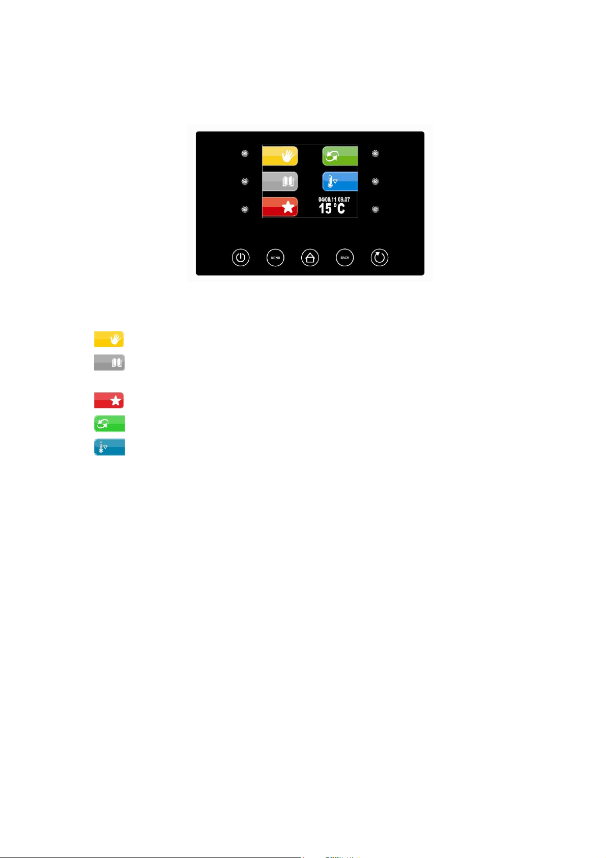
6.1.1 Pre-selection page
The Pre-selection page represents the "start point" foe navigating the user interface.
The functions enabled and the dates data, time and temperature in cabinet are present in the pre-selection page.
All final user selections will start from the pre-selection page.
The 5 “interactive” keys will allow to select:
- MANUAL: i.e. selection, setting and running a manual cooling or heating cycle.
- PROGRAMS: i.e. the selection and/or modification of automatic retarder-proffer cycles saved in the
memory
- FAVOURITES: i.e. the quick recall of the last 10 performed.
- AUTOMATIC: i.e. the selection, setting and execution of a complete automatic retarder-proofer cycle.
- PRE-COOLING: i.e. the execution of a cabinet pre-cooling cycle
The 2 active “navigation” keys will allow to select:
- ON/STANDBY to take the machine back to STANDBY status
- MENU to access the pre-selection page options screen
Page 19 of
62
 Loading...