

Page 1

SMM-8 Microphone Mixer Instructions
The SMM-8 is a 4 channel simple microphone mixer designed to expand the area of coverage of a large area to be
monitored. It can be used directly with DVRs, IP cameras or can be connected directly to ETS base stations. Note- the
audio output of the SMM-8 is “line level” (0db).
SM1 Microphone Placement
Locate the SM1s microphones as close as possible to the areas of interest in the space to be monitored. Do not mount
the microphones near air conditioning vents, light fixtures or electrical equipment. The SM1s should be placed at least 5
feet away from the subject(s) to be monitored. An SM1 is still useable in the range of 15-25 feet but is dependent on the
level of background noise in the area. Experimentation in the environment will determine what distances work best.
SMM-8 location and power
The SMM-8 interface box is designed to be located next to a DVR or I/P camera. The SMM-8 requires a 120VAC power
source within 6 feet of its location. If this is not possible in your application, you can splice in up to 100 feet of 18 awg, 2
conductor cable to extend the distance between the AC power source and the SMM-8.
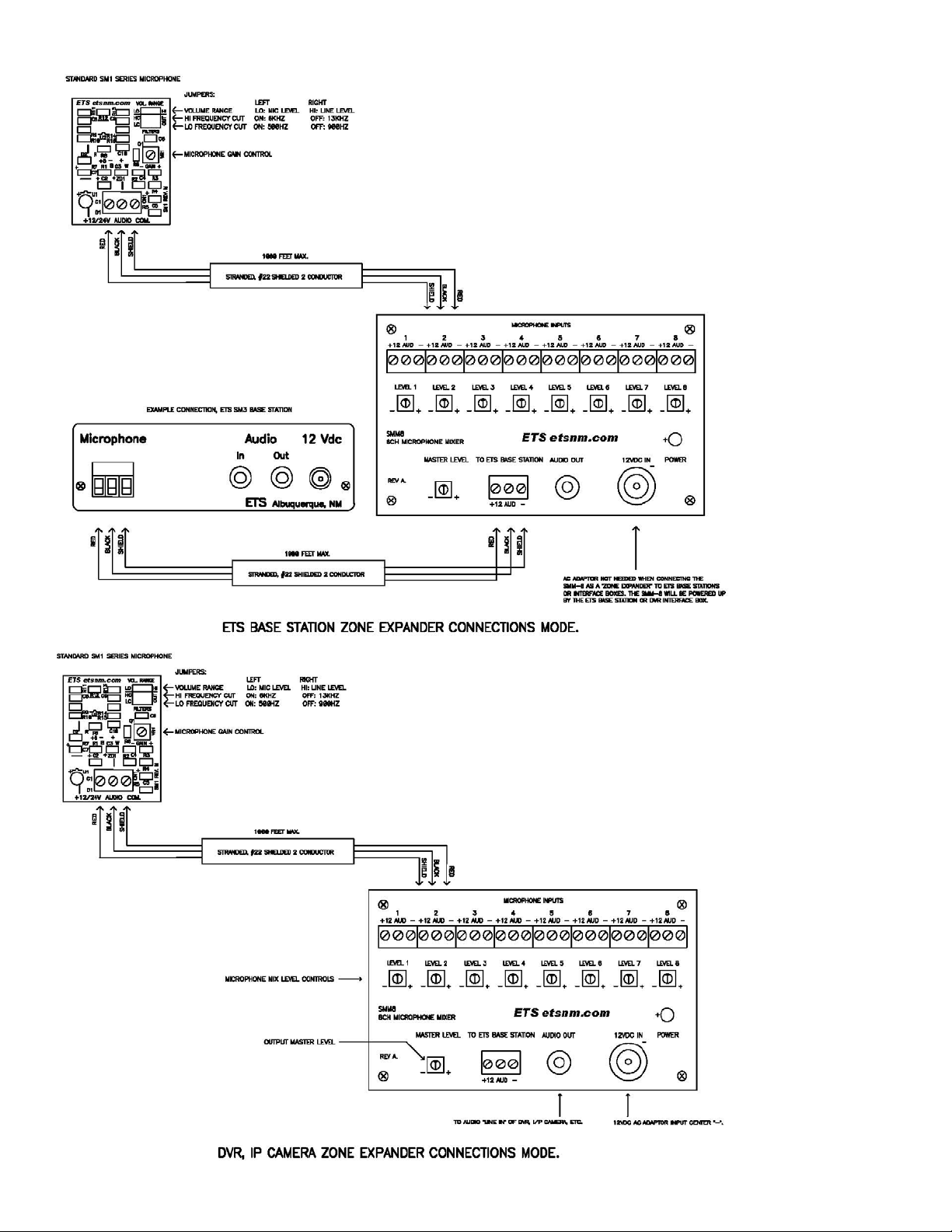
Cable Run
Run up to 4 each 22 gauge, stranded, two conductor shielded cable between the SMM-8 mixer and the SM1
microphones. Keep the cable run distances under 1,000 feet and away from AC power sources, light fixtures and
electrical equipment. See Figure 1 for connection diagram.
SMM-8 level controls
Each microphone level can be adjusted to a higher or lower volume so that all microphones can be balanced out for
similar sound levels (one microphone dominates the overall sound, for example). Experiment by adjusting each level
control and the master level control to achieve the desired overall volume.
SMM-8 audio output.
This output is typically connected to the audio input of the DVR, I/P camera, etc. You can extend this output up to 1000
feet using audio coaxial cable and 2 field installable RCA (or 3.5mm) connectors. This output can also be connected to
any ETS base station microphone input. In this case, the AC adaptor that comes with the SMM-8 is not required because
it is powered up by the ETS base station. All three connections, +, -, and audio are required along with the cable
requirements or 2 conductor shielded. See connection diagrams.
Caution
It may be against the law to install this microphone kit in certain environments. It may also be against the law to record conversations of
the person(s) being monitored without their knowledge. It is the responsibility of the installation company and end-user to det ermine if
the application of this product is legal. These laws vary from state to state. If you are not informed on these matters, consult a qualified
attorney or contact the appropriate state agency. A sticker is provided with this kit for the applications where notification must be
posted.
Warranty
All ETS products carry a one year parts and labor warranty. This warranty does not cover damages as a result of misuse, improper
handling of the unit or exposure to extreme temperatures or moisture. At its discretion, ETS reserves the right to repair or replace this
unit under the conditions of the warranty. If you experience problems with your equipment call ETS at: 505-888-3923 to obtain a return
authorization number. Equipment requiring repair beyond the warrant y period or un its that have been damaged or are not covered
under the warranty can be repaired by ETS for a minimal cost under most conditions.
Made in the USA
by
Page 2
 Loading...